EP3224668B1 - Hinge for spectacle temples - Google Patents
Hinge for spectacle temples Download PDFInfo
- Publication number
- EP3224668B1 EP3224668B1 EP15810771.4A EP15810771A EP3224668B1 EP 3224668 B1 EP3224668 B1 EP 3224668B1 EP 15810771 A EP15810771 A EP 15810771A EP 3224668 B1 EP3224668 B1 EP 3224668B1
- Authority
- EP
- European Patent Office
- Prior art keywords
- hinge
- branch
- knuckle
- edge
- arc
- Prior art date
- Legal status (The legal status is an assumption and is not a legal conclusion. Google has not performed a legal analysis and makes no representation as to the accuracy of the status listed.)
- Active
Links
- 239000011521 glass Substances 0.000 claims description 16
- 241001080024 Telles Species 0.000 description 1
- 230000003247 decreasing effect Effects 0.000 description 1
Images


Classifications
-
- G—PHYSICS
- G02—OPTICS
- G02C—SPECTACLES; SUNGLASSES OR GOGGLES INSOFAR AS THEY HAVE THE SAME FEATURES AS SPECTACLES; CONTACT LENSES
- G02C5/00—Constructions of non-optical parts
- G02C5/22—Hinges
-
- G—PHYSICS
- G02—OPTICS
- G02C—SPECTACLES; SUNGLASSES OR GOGGLES INSOFAR AS THEY HAVE THE SAME FEATURES AS SPECTACLES; CONTACT LENSES
- G02C5/00—Constructions of non-optical parts
- G02C5/22—Hinges
- G02C5/2281—Special hinge screws
-
- G—PHYSICS
- G02—OPTICS
- G02C—SPECTACLES; SUNGLASSES OR GOGGLES INSOFAR AS THEY HAVE THE SAME FEATURES AS SPECTACLES; CONTACT LENSES
- G02C2200/00—Generic mechanical aspects applicable to one or more of the groups G02C1/00 - G02C5/00 and G02C9/00 - G02C13/00 and their subgroups
- G02C2200/20—Friction elements
Definitions
- a spectacle arm hinge generally comprises a knuckle integral with the frame, a mortise provided in the arm, in which this knuckle is engaged, and a screw engaged through the arm and the knuckle, forming the pivot axis of the plugged.
- This friction has the drawback of gradually decreasing as the pair of glasses is used, due to wear of the surfaces in contact, and the screw can loosen more or less, causing play to appear in the branch movement. This results in a more difficult use of the pair of glasses, an impression, for the user, of poor quality of the pair of glasses, and the risk of disassembly of a branch.
- the object of the present invention is to remedy these drawbacks, by providing a hinge in which friction is kept at a sufficiently high level throughout the duration of use of the pair of glasses, so as to maintain a controlled movement of the glasses. branches, and which presents a reduced risk of loosening the screw and therefore of disassembly of a branch.
- the affected hinge according to rev. independent 1, 2. comprises, in a manner known per se, a knuckle integral with a base intended to be fixed to the frame of the pair of glasses, a mortise provided in the branch, in which this knuckle is intended to be engaged, and a screw, or pin or similar member, intended to be engaged through the branch and the knuckle so as to assemble the branch to the knuckle and to form the pivot axis of the branch.
- the hinge according to the invention thus comprises a shoe bearing against the knuckle by an extended bearing wall, and which is urged against the edge of this knuckle by elastic means.
- This extended bearing wall and this stress make it possible to create friction between the knuckle and the branch, which is not reduced over the period of use of the pair of glasses. Adequate control of the movement of the limb is thus maintained throughout this period of use.
- the notch makes it possible to form a housing for the pad in the folding position of the branch along the frame, and therefore allows the branch to be brought into this folding position notwithstanding the relative angular size of the pad.
- the pad pressed against the knuckle, also allows a radial tension to exist on the screw, which turns out to oppose the unscrewing of this screw favorably.
- the arc of a circle along which said edge extends is at least 135 °.
- the pad is dimensioned so that its bearing wall extends over an arc the length of which is of the order of one third of that along which said edge extends.
- This area ratio turns out to be a good compromise between the extent of the bearing wall and the angular size of the pad.
- said bearing wall extends over an arc of the order of 70 °; said section then extends over an arc of the order of 210 °.
- the elastic means consists of a helical spring interposed between the pad and a wall of the branch.
- This wall of the branch is in particular the wall delimiting the bottom of the mortise.
- This base may have a bore in which one end of the spring is engaged, so as to ensure the mounting of this spring on this branch.
- the pad advantageously comprises, on its side opposite to said bearing wall, a tubular extension capable of receiving the spring therein. The connection of the spring and the shoe is thus well ensured.
- the screw may have a threaded distal portion having an external thread diameter greater than the diameter of the portion of the body of the screw intended to extend through the bore that the knuckle comprises to receive this screw.
- distal is meant the end portion of the body of the screw which is opposite the head of this screw.
- Said bore consequently has a diameter suitable for being traversed by said threaded distal portion of the screw, therefore a diameter appreciably greater than that of said portion of the body of the screw; there is thus a clearance between the wall of the knuckle delimiting the bore and this portion of the body of the screw.
- the pressure exerted on the knuckle by said elastic means brings the knuckle into contact with this portion of the body of the screw, which allows the knuckle to extend below said threaded portion of the screw and thus form a surface axial stop which opposes the retraction of the screw in the event of the beginning of unscrewing of the latter.
- the figure 1 shows a hinge 1 for a branch of glasses 2, comprising a knuckle 3, a mortise 4 formed in the branch 2, in which this knuckle 3 is engaged, a pad 5, a spring 6 and a screw 7 engaged through holes made in branch 2 and knuckle 3 so as to assemble this branch to this knuckle and to form the pivot axis of branch 2.
- Knuckle 3 is better visible on figures 2 and 3 . It is integral with a base 3a intended to be fixed to the frame (not shown) of the pair of glasses and has a uniformly convex slice 3b, in an arc of a circle centered on the pivot axis of the branch 2. This slice 3b extends over an arc of the order of 210 °, from a notch 8 formed by knuckle 3 on its internal side.
- This notch 8 is delimited, on one side, by the portion of the knuckle 3 connected to the base 3a, and, on the other side, by said edge 3b.
- Mortise 4 is fitted in branch 2, from the end of this branch. Its bottom has a bore 9 in which one end of the spring 6 is engaged, so as to ensure the mounting of this spring on the branch 2.
- the pad 5 has a body 5a forming, on one side, a support wall 5b of the pad against the edge 3b; on its side opposite to this support wall 5b, the body 5a forms a tubular extension 5c.
- the body 5a is dimensioned so that the support wall 5b extends over an arc of the order of a third of that in which the section 3b extends, ie over an arc of approximately 70 °.
- the support wall 5b has the same curvature as this section 3b.
- the tubular extension 5c is adapted to receive the spring 6 therein, in an adjusted manner.
- the spring 6 urges the pad 5 towards the edge 3b, so that the support wall 5b comes to bear against the edge 3b along an extended surface, and that this wall 5b is pressed against this edge. Friction is thus created between the knuckle 3 and the branch 2 which does not decrease over the duration of the use of the pair of glasses, allowing adequate control of the movement of the branch 2 to be maintained throughout the whole. of this duration of use.
- the notch 8 makes it possible to form a housing for the pad 5 in the folding position of the branch 2 along the frame (cf. figure 5 ), and therefore allows branch 2 can be brought into this folding position notwithstanding the relative angular size of the pad 5.
- the pad 5, pressed against the knuckle 3, also allows a radial tension to exist on the screw 7, which turns out to oppose the unscrewing of this screw favorably.
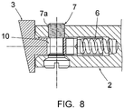
- the screw 7 has a threaded distal portion 7a having an external thread diameter greater than the diameter of the portion 7b of the body of the screw 7 intended to extend through the bore that the knuckle comprises to receive this screw .
- the bore 10 of the knuckle 3 has a diameter suitable for being traversed by the threaded distal portion 7a of the screw 7, therefore a diameter appreciably greater than that of the portion 7b of the body of the screw. There is thus a clearance between the wall of the knuckle 3 delimiting the bore 10 and this portion 7b.
- the pressure exerted on the knuckle 3 by the spring 6 brings the knuckle 3 into contact with this portion 7b, which allows the knuckle 3 to extend below the threaded portion 7a and thus form an axial abutment surface opposing the retreat of screw 7 if the latter begins to unscrew. This unscrewing is thus effectively prevented.
- the invention thus provides a hinge for a spectacle arm which has the aforementioned decisive advantages over the hinges according to the prior art.
Description
La présente invention concerne une charnière pour une branche de lunettes. Une charnière de branche de lunettes comprend généralement un charnon solidaire de la monture, une mortaise aménagée dans la branche, dans laquelle ce charnon est engagé, et une vis engagée au travers de la branche et du charnon, formant l'axe de pivotement de la branche.The present invention relates to a hinge for a temple arm. A spectacle arm hinge generally comprises a knuckle integral with the frame, a mortise provided in the arm, in which this knuckle is engaged, and a screw engaged through the arm and the knuckle, forming the pivot axis of the plugged.
Les dimensions respectives du charnon et de la mortaise et/ou le serrage de la vis permettent l'existence de frottements au niveau de la charnière, faisant que la branche reste en position dépliée lorsque la paire de lunettes est manipulée.The respective dimensions of the knuckle and the mortise and / or the tightening of the screw allow the existence of friction at the level of the hinge, causing the branch to remain in the unfolded position when the pair of glasses is handled.
Ces frottements ont pour inconvénient de diminuer progressivement au fur et à mesure de l'utilisation de la paire de lunettes, par suite d'usure des surfaces en contact, et la vis peut se desserrer plus ou moins, faisant que du jeu apparaît dans le mouvement de la branche. Il en résulte une utilisation plus difficile de la paire de lunettes, une impression, pour l'utilisateur, de qualité médiocre de la paire de lunette, et le risque de désassemblage d'une branche.This friction has the drawback of gradually decreasing as the pair of glasses is used, due to wear of the surfaces in contact, and the screw can loosen more or less, causing play to appear in the branch movement. This results in a more difficult use of the pair of glasses, an impression, for the user, of poor quality of the pair of glasses, and the risk of disassembly of a branch.
Exemples de charnières conventionnelles sont divulguées par
La présente invention a pour objectif de remédier à ces inconvénients, en fournissant une charnière dans laquelle des frottements sont conservés à un niveau suffisamment élevé tout au long de la durée d'utilisation de la paire de lunettes, de façon à conserver un mouvement contrôlé des branches, et qui présente un risque amoindri de desserrage de la vis et donc de désassemblage d'une branche.The object of the present invention is to remedy these drawbacks, by providing a hinge in which friction is kept at a sufficiently high level throughout the duration of use of the pair of glasses, so as to maintain a controlled movement of the glasses. branches, and which presents a reduced risk of loosening the screw and therefore of disassembly of a branch.
La charnière concernée, selon la rev. indépendante 1, 2. comprend de manière connue en soi, un charnon solidaire d'une embase destinée à être fixée à la monture de la paire de lunettes, une mortaise aménagée dans la branche, dans laquelle ce charnon est destiné à être engagé, et une vis, ou broche ou organe similaire, destinée à être engagée au-travers de la branche et du charnon de manière à assembler la branche au charnon et à former l'axe de pivotement de la branche.The affected hinge, according to rev. independent 1, 2. comprises, in a manner known per se, a knuckle integral with a base intended to be fixed to the frame of the pair of glasses, a mortise provided in the branch, in which this knuckle is intended to be engaged, and a screw, or pin or similar member, intended to be engaged through the branch and the knuckle so as to assemble the branch to the knuckle and to form the pivot axis of the branch.
Selon l'invention,
- le charnon présente une tranche convexe, en arc de cercle centré sur l'axe de pivotement de la branche, et forme une encoche sur le côté interne du charnon, délimitée, sur un côté, par l'embase ou par la portion du charnon reliée à cette embase, et, sur l'autre côté, par ladite tranche ;
- la charnière comprend un patin destiné à venir en appui contre ladite tranche, formant une paroi d'appui contre cette tranche et ayant la même courbure que cette tranche, cette paroi d'appui s'étendant sur un arc représentant au moins un quart de l'arc selon lequel s'étend la tranche ;
- la charnière comprend un moyen élastique sollicitant le patin vers ladite tranche, de telle sorte que ladite paroi d'appui soit pressée contre cette tranche,
- ladite encoche est dimensionnée de façon à loger partiellement le patin dans la position de repliage de la branche le long de la monture.
- the knuckle has a convex edge, in an arc of a circle centered on the pivot axis of the branch, and forms a notch on the internal side of the knuckle, delimited, on one side, by the base or by the portion of the connected knuckle to this base, and, on the other side, by said edge;
- the hinge comprises a pad intended to come to bear against said edge, forming a bearing wall against this edge and having the same curvature as this edge, this bearing wall extending over an arc representing at least a quarter of the arc along which the edge extends;
- the hinge comprises an elastic means urging the pad towards said edge, so that said bearing wall is pressed against this edge,
- said notch is dimensioned so as to partially accommodate the pad in the folding position of the branch along the frame.
Il sera compris que par l'expression "côté interne du charnon", il est fait référence au côté du charnon se trouvant vers l'intérieur de la paire de lunettes, donc tourné vers l'autre branche de cette paire de lunettes.It will be understood that by the expression “internal side of the knuckle”, reference is made to the side of the knuckle located towards the inside of the pair of glasses, therefore facing the other branch of this pair of glasses.
La charnière selon l'invention comprend ainsi un patin venant en appui contre le charnon par une paroi d'appui étendue, et qui est sollicité contre la tranche de ce charnon par un moyen élastique. Cette paroi d'appui étendue et cette sollicitation permettent de créer des frottements entre le charnon et la branche, ne se réduisant pas au long de la durée d'utilisation de la paire de lunettes. Un contrôle adéquat du mouvement de la branche est ainsi conservé sur l'ensemble de cette durée d'utilisation. L'encoche permet de former un logement pour le patin dans la position de repliage de la branche le long de la monture, et permet donc que la branche puisse être amenée dans cette position de repliage nonobstant le relatif encombrement angulaire du patin.The hinge according to the invention thus comprises a shoe bearing against the knuckle by an extended bearing wall, and which is urged against the edge of this knuckle by elastic means. This extended bearing wall and this stress make it possible to create friction between the knuckle and the branch, which is not reduced over the period of use of the pair of glasses. Adequate control of the movement of the limb is thus maintained throughout this period of use. The notch makes it possible to form a housing for the pad in the folding position of the branch along the frame, and therefore allows the branch to be brought into this folding position notwithstanding the relative angular size of the pad.
Le patin, pressé contre le charnon, permet également de faire exister une tension radiale sur la vis, qui s'avère s'opposer favorablement au dévissage de cette vis.The pad, pressed against the knuckle, also allows a radial tension to exist on the screw, which turns out to oppose the unscrewing of this screw favorably.
De préférence, l'arc de cercle selon lequel s'étend ladite tranche est d'au moins 135°.Preferably, the arc of a circle along which said edge extends is at least 135 °.
De préférence, le patin est dimensionné de manière à ce que sa paroi d'appui s'étende sur un arc dont la longueur est de l'ordre du tiers de celui selon lequel s'étend ladite tranche.Preferably, the pad is dimensioned so that its bearing wall extends over an arc the length of which is of the order of one third of that along which said edge extends.
Ce rapport de surface s'avère être un bon compromis entre l'étendue de la paroi d'appui et l'encombrement angulaire du patin.This area ratio turns out to be a good compromise between the extent of the bearing wall and the angular size of the pad.
De préférence, ladite paroi d'appui s'étend sur un arc de l'ordre de 70° ; ladite tranche s'étend alors sur un arc de l'ordre de 210°.Preferably, said bearing wall extends over an arc of the order of 70 °; said section then extends over an arc of the order of 210 °.
Selon une forme de réalisation préférée de l'invention, le moyen élastique est constitué par un ressort hélicoïdal interposé entre le patin et une paroi de la branche.According to a preferred embodiment of the invention, the elastic means consists of a helical spring interposed between the pad and a wall of the branch.
Cette paroi de la branche est notamment la paroi délimitant le fond de la mortaise.This wall of the branch is in particular the wall delimiting the bottom of the mortise.
Ce fond peut présenter un alésage dans lequel est engagée une extrémité du ressort, de façon à assurer le montage de ce ressort sur cette branche.This base may have a bore in which one end of the spring is engaged, so as to ensure the mounting of this spring on this branch.
Le patin comprend avantageusement, sur son côté opposé à ladite paroi d'appui, une extension tubulaire apte à recevoir le ressort en elle. La liaison du ressort et du patin est ainsi bien assurée.The pad advantageously comprises, on its side opposite to said bearing wall, a tubular extension capable of receiving the spring therein. The connection of the spring and the shoe is thus well ensured.
La vis peut présenter une portion distale filetée ayant un diamètre externe de filet supérieur au diamètre qu'a la portion du corps de la vis destinée à s'étendre au travers de l'alésage que comprend le charnon pour recevoir cette vis. Par "distale", on entend la portion d'extrémité du corps de la vis qui est opposée à la tête de cette vis.The screw may have a threaded distal portion having an external thread diameter greater than the diameter of the portion of the body of the screw intended to extend through the bore that the knuckle comprises to receive this screw. By "distal" is meant the end portion of the body of the screw which is opposite the head of this screw.
Ledit alésage présente par conséquent un diamètre adapté à être traversé par ladite portion distale filetée de la vis, donc un diamètre notablement supérieur à celui de ladite portion du corps de la vis ; il existe ainsi un jeu entre la paroi du charnon délimitant l'alésage et cette portion du corps de la vis. La pression exercée sur le charnon par ledit moyen élastique amène le charnon au contact de cette portion du corps de la vis, ce qui permet que le charnon s'étende en dessous de ladite portion filetée de la vis et qu'il forme ainsi une surface axiale de butée venant s'opposer au recul de la vis en cas de début de dévissage de cette dernière.Said bore consequently has a diameter suitable for being traversed by said threaded distal portion of the screw, therefore a diameter appreciably greater than that of said portion of the body of the screw; there is thus a clearance between the wall of the knuckle delimiting the bore and this portion of the body of the screw. The pressure exerted on the knuckle by said elastic means brings the knuckle into contact with this portion of the body of the screw, which allows the knuckle to extend below said threaded portion of the screw and thus form a surface axial stop which opposes the retraction of the screw in the event of the beginning of unscrewing of the latter.
Ce dévissage est ainsi empêché de manière efficace.This unscrewing is thus effectively prevented.
L'invention sera bien comprise, et d'autres caractéristiques et avantages de celle-ci apparaîtront, en référence au dessin schématique annexé ; ce dessin représente, à titre d'exemple non limitatif, une forme de réalisation préférée de la charnière concernée.
- La
figure 1 est une vue de cette charnière de côté, à l'état d'assemblage, selon une première forme de réalisation ; - la
figure 2 est une vue en perspective du charnon que comprend la charnière ; - la
figure 3 est une vue de dessus de trois éléments que comprend la charnière, en éclaté ; - la
figure 4 est une vue de ces éléments similaire à lafigure 3 , dans la position de dépliage de la branche, l'un des éléments étant vu en coupe ; - la
figure 5 en est une vue de ces mêmes éléments, similaire à lafigure 4 , dans la position de repliage de la branche le long de la monture de la paire de lunettes ; - la
figure 6 est une vue en perspective éclatée de trois éléments que comprend la charnière selon une deuxième forme de réalisation ; - la
figure 7 est une vue de côté d'une vis que comprend la charnière selon cette deuxième forme de réalisation, et - la
figure 8 est une vue de côté de la charnière selon cette deuxième forme de réalisation, à l'état d'assemblage.
- The
figure 1 is a side view of this hinge, in the assembled state, according to a first embodiment; - the
figure 2 is a perspective view of the knuckle that includes the hinge; - the
figure 3 is a top view of three elements included in the hinge, exploded; - the
figure 4 is a view of these elements similar to thefigure 3 , in the unfolding position of the branch, one of the elements being seen in section; - the
figure 5 is a view of these same elements, similar to thefigure 4 , in the folded position of the branch along the frame of the pair of glasses; - the
figure 6 is an exploded perspective view of three elements included in the hinge according to a second embodiment; - the
figure 7 is a side view of a screw included in the hinge according to this second embodiment, and - the
figure 8 is a side view of the hinge according to this second embodiment, in the assembled state.
La
Le charnon 3 est mieux visible sur les
Cette encoche 8 est délimitée, sur un côté, par la portion du charnon 3 reliée à l'embase 3a, et, sur l'autre côté, par ladite tranche 3b.This
La mortaise 4 est aménagée dans la branche 2, depuis l'extrémité de cette branche. Son fond présente un alésage 9 dans lequel est engagée une extrémité du ressort 6, de façon à assurer le montage de ce ressort sur la branche 2.Mortise 4 is fitted in
Le patin 5 présente un corps 5a formant, sur un côté, une paroi 5b d'appui du patin contre la tranche 3b ; sur son côté opposé à cette paroi d'appui 5b, le corps 5a forme une extension tubulaire 5c.The
Le corps 5a est dimensionné de manière à ce que la paroi d'appui 5b s'étende sur un arc de l'ordre du tiers de celui selon lequel s'étend la tranche 3b, soit sur un arc d'environ 70°. La paroi d'appui 5b a la même courbure que cette tranche 3b.The
L'extension tubulaire 5c est apte à recevoir le ressort 6 en elle, de façon ajustée.The
A l'état assemblé de la charnière, comme visible sur les
Le patin 5, pressé contre le charnon 3, permet également de faire exister une tension radiale sur la vis 7, qui s'avère s'opposer favorablement au dévissage de cette vis.The
En référence à la
Selon cette deuxième forme de réalisation, et comme visible sur la
Il apparaît sur la
L'invention fournit ainsi une charnière pour une branche de lunettes qui présente des avantages déterminants, précités, par rapport aux charnières selon la technique antérieure .The invention thus provides a hinge for a spectacle arm which has the aforementioned decisive advantages over the hinges according to the prior art.
Claims (9)
characterized in that:
Applications Claiming Priority (2)
| Application Number | Priority Date | Filing Date | Title |
|---|---|---|---|
| FR1461679A FR3029303B1 (en) | 2014-11-28 | 2014-11-28 | HINGE FOR A BRONZE OF GLASSES |
| PCT/IB2015/059180 WO2016084045A1 (en) | 2014-11-28 | 2015-11-27 | Hinge for spectacle temples |
Publications (2)
| Publication Number | Publication Date |
|---|---|
| EP3224668A1 EP3224668A1 (en) | 2017-10-04 |
| EP3224668B1 true EP3224668B1 (en) | 2021-10-27 |
Family
ID=52392129
Family Applications (1)
| Application Number | Title | Priority Date | Filing Date |
|---|---|---|---|
| EP15810771.4A Active EP3224668B1 (en) | 2014-11-28 | 2015-11-27 | Hinge for spectacle temples |
Country Status (3)
| Country | Link |
|---|---|
| EP (1) | EP3224668B1 (en) |
| FR (1) | FR3029303B1 (en) |
| WO (1) | WO2016084045A1 (en) |
Families Citing this family (2)
| Publication number | Priority date | Publication date | Assignee | Title |
|---|---|---|---|---|
| USD900922S1 (en) * | 2019-05-14 | 2020-11-03 | Wen-Tse HUANG | Eyeglass magnet connection |
| USD900921S1 (en) * | 2019-05-14 | 2020-11-03 | Wen-Tse HUANG | Eyeglass magnet connection |
Family Cites Families (3)
| Publication number | Priority date | Publication date | Assignee | Title |
|---|---|---|---|---|
| JPS5983128A (en) * | 1982-11-02 | 1984-05-14 | Toshiaki Osawa | Spectacles |
| FR2737020B1 (en) * | 1995-07-21 | 1997-09-19 | Chevassus | EYEWEAR FRAME WITH ELASTIC DOUBLE HINGE |
| KR200194192Y1 (en) * | 2000-03-21 | 2000-09-01 | 김광남 | Glasses for rotatiug theirlegs |
-
2014
- 2014-11-28 FR FR1461679A patent/FR3029303B1/en not_active Expired - Fee Related
-
2015
- 2015-11-27 WO PCT/IB2015/059180 patent/WO2016084045A1/en active Application Filing
- 2015-11-27 EP EP15810771.4A patent/EP3224668B1/en active Active
Also Published As
| Publication number | Publication date |
|---|---|
| FR3029303A1 (en) | 2016-06-03 |
| WO2016084045A1 (en) | 2016-06-02 |
| FR3029303B1 (en) | 2016-12-09 |
| EP3224668A1 (en) | 2017-10-04 |
Similar Documents
| Publication | Publication Date | Title |
|---|---|---|
| FR2616670A1 (en) | GOLF CLUB WITH REMOVABLE HEAD | |
| CH687829A5 (en) | Device for assembling two elements to one another. | |
| CA2907637C (en) | Ball-jointed device for suspending a turbomachine from a pylon or for suspending equipment from the body of the turbomachine | |
| WO2010100087A1 (en) | Frame for spectacles with telescopic hinges, and hinge for the frame | |
| EP3224668B1 (en) | Hinge for spectacle temples | |
| FR2800173A1 (en) | Spectacle frame has hinged bridge-piece which can be opened to allow lenses to be removed, replaced or changed | |
| WO2013139817A1 (en) | Telescopic hinge for spectacles frame | |
| FR3062927A1 (en) | GLASSES ORIENTATION OF THE BRANCHES ACCORDING TO SEVERAL PLANS | |
| FR2690760A1 (en) | Sprung hinge, esp. for spectacle frame - comprises sprung rod with spherical tip in cavity in one component, engaging with slot and socket in other | |
| EP0385822A1 (en) | Spectacle bow and spectacle frame therefor | |
| WO2014111422A1 (en) | Spectacle frame having telescopic hinges with an adjustable offset spring, mounted in a rotary end piece | |
| FR2816072A1 (en) | Spectacle frame spring-loaded hinge has spring tension adjuster in form of screw in closed end of sleeve containing spring and rod | |
| CA2804669A1 (en) | Spectacles frame with telescopic hinges and offset spring | |
| EP2035884B1 (en) | Side-piece for spectacles and spectacles comprising such a side-piece | |
| FR2754914A1 (en) | METHOD OF LINKING BETWEEN A BRANCH AND A EYEWEAR FRONT AND EYEGLASS HINGE | |
| FR2725046A1 (en) | Adjustable elastic hinge for arm of spectacle frame | |
| FR3102043A1 (en) | Set forming a riding spur | |
| EP0851264A1 (en) | Elastic hinge | |
| EP1412805A1 (en) | Novel system for mounting sidearms on spectacles | |
| FR2941309A1 (en) | Spectacle frame, has helicoidal spring whose cross bar provides connection between branches and frame face, where end piece of face and another end piece of branch are maintained and engaged at ends of spring | |
| FR2718537A1 (en) | Hinge for spectacle frame with telescopic rocking arms | |
| FR2751762A1 (en) | Spring=loaded spectacle frame hinge | |
| WO2004097500A2 (en) | Hinge which is intended, in particular, for spectacle frames | |
| FR3092178A1 (en) | Eyeglass frame with over-opening flexibility | |
| FR2803920A1 (en) | Hinge for spectacle frame has curved rod on arm of spectacles forming pivot pin for bracket |
Legal Events
| Date | Code | Title | Description |
|---|---|---|---|
| STAA | Information on the status of an ep patent application or granted ep patent |
Free format text: STATUS: THE INTERNATIONAL PUBLICATION HAS BEEN MADE |
|
| PUAI | Public reference made under article 153(3) epc to a published international application that has entered the european phase |
Free format text: ORIGINAL CODE: 0009012 |
|
| STAA | Information on the status of an ep patent application or granted ep patent |
Free format text: STATUS: REQUEST FOR EXAMINATION WAS MADE |
|
| 17P | Request for examination filed |
Effective date: 20170621 |
|
| AK | Designated contracting states |
Kind code of ref document: A1 Designated state(s): AL AT BE BG CH CY CZ DE DK EE ES FI FR GB GR HR HU IE IS IT LI LT LU LV MC MK MT NL NO PL PT RO RS SE SI SK SM TR |
|
| AX | Request for extension of the european patent |
Extension state: BA ME |
|
| DAV | Request for validation of the european patent (deleted) | ||
| DAX | Request for extension of the european patent (deleted) | ||
| GRAP | Despatch of communication of intention to grant a patent |
Free format text: ORIGINAL CODE: EPIDOSNIGR1 |
|
| STAA | Information on the status of an ep patent application or granted ep patent |
Free format text: STATUS: GRANT OF PATENT IS INTENDED |
|
| INTG | Intention to grant announced |
Effective date: 20210519 |
|
| GRAS | Grant fee paid |
Free format text: ORIGINAL CODE: EPIDOSNIGR3 |
|
| GRAA | (expected) grant |
Free format text: ORIGINAL CODE: 0009210 |
|
| STAA | Information on the status of an ep patent application or granted ep patent |
Free format text: STATUS: THE PATENT HAS BEEN GRANTED |
|
| AK | Designated contracting states |
Kind code of ref document: B1 Designated state(s): AL AT BE BG CH CY CZ DE DK EE ES FI FR GB GR HR HU IE IS IT LI LT LU LV MC MK MT NL NO PL PT RO RS SE SI SK SM TR |
|
| REG | Reference to a national code |
Ref country code: GB Ref legal event code: FG4D Free format text: NOT ENGLISH |
|
| REG | Reference to a national code |
Ref country code: CH Ref legal event code: EP |
|
| REG | Reference to a national code |
Ref country code: DE Ref legal event code: R096 Ref document number: 602015074505 Country of ref document: DE |
|
| REG | Reference to a national code |
Ref country code: AT Ref legal event code: REF Ref document number: 1442307 Country of ref document: AT Kind code of ref document: T Effective date: 20211115 |
|
| REG | Reference to a national code |
Ref country code: IE Ref legal event code: FG4D Free format text: LANGUAGE OF EP DOCUMENT: FRENCH |
|
| REG | Reference to a national code |
Ref country code: LT Ref legal event code: MG9D |
|
| REG | Reference to a national code |
Ref country code: NL Ref legal event code: MP Effective date: 20211027 |
|
| REG | Reference to a national code |
Ref country code: AT Ref legal event code: MK05 Ref document number: 1442307 Country of ref document: AT Kind code of ref document: T Effective date: 20211027 |
|
| PG25 | Lapsed in a contracting state [announced via postgrant information from national office to epo] |
Ref country code: RS Free format text: LAPSE BECAUSE OF FAILURE TO SUBMIT A TRANSLATION OF THE DESCRIPTION OR TO PAY THE FEE WITHIN THE PRESCRIBED TIME-LIMIT Effective date: 20211027 Ref country code: LT Free format text: LAPSE BECAUSE OF FAILURE TO SUBMIT A TRANSLATION OF THE DESCRIPTION OR TO PAY THE FEE WITHIN THE PRESCRIBED TIME-LIMIT Effective date: 20211027 Ref country code: FI Free format text: LAPSE BECAUSE OF FAILURE TO SUBMIT A TRANSLATION OF THE DESCRIPTION OR TO PAY THE FEE WITHIN THE PRESCRIBED TIME-LIMIT Effective date: 20211027 Ref country code: BG Free format text: LAPSE BECAUSE OF FAILURE TO SUBMIT A TRANSLATION OF THE DESCRIPTION OR TO PAY THE FEE WITHIN THE PRESCRIBED TIME-LIMIT Effective date: 20220127 Ref country code: AT Free format text: LAPSE BECAUSE OF FAILURE TO SUBMIT A TRANSLATION OF THE DESCRIPTION OR TO PAY THE FEE WITHIN THE PRESCRIBED TIME-LIMIT Effective date: 20211027 |
|
| PG25 | Lapsed in a contracting state [announced via postgrant information from national office to epo] |
Ref country code: IS Free format text: LAPSE BECAUSE OF FAILURE TO SUBMIT A TRANSLATION OF THE DESCRIPTION OR TO PAY THE FEE WITHIN THE PRESCRIBED TIME-LIMIT Effective date: 20220227 Ref country code: SE Free format text: LAPSE BECAUSE OF FAILURE TO SUBMIT A TRANSLATION OF THE DESCRIPTION OR TO PAY THE FEE WITHIN THE PRESCRIBED TIME-LIMIT Effective date: 20211027 Ref country code: PT Free format text: LAPSE BECAUSE OF FAILURE TO SUBMIT A TRANSLATION OF THE DESCRIPTION OR TO PAY THE FEE WITHIN THE PRESCRIBED TIME-LIMIT Effective date: 20220228 Ref country code: PL Free format text: LAPSE BECAUSE OF FAILURE TO SUBMIT A TRANSLATION OF THE DESCRIPTION OR TO PAY THE FEE WITHIN THE PRESCRIBED TIME-LIMIT Effective date: 20211027 Ref country code: NO Free format text: LAPSE BECAUSE OF FAILURE TO SUBMIT A TRANSLATION OF THE DESCRIPTION OR TO PAY THE FEE WITHIN THE PRESCRIBED TIME-LIMIT Effective date: 20220127 Ref country code: NL Free format text: LAPSE BECAUSE OF FAILURE TO SUBMIT A TRANSLATION OF THE DESCRIPTION OR TO PAY THE FEE WITHIN THE PRESCRIBED TIME-LIMIT Effective date: 20211027 Ref country code: LV Free format text: LAPSE BECAUSE OF FAILURE TO SUBMIT A TRANSLATION OF THE DESCRIPTION OR TO PAY THE FEE WITHIN THE PRESCRIBED TIME-LIMIT Effective date: 20211027 Ref country code: HR Free format text: LAPSE BECAUSE OF FAILURE TO SUBMIT A TRANSLATION OF THE DESCRIPTION OR TO PAY THE FEE WITHIN THE PRESCRIBED TIME-LIMIT Effective date: 20211027 Ref country code: GR Free format text: LAPSE BECAUSE OF FAILURE TO SUBMIT A TRANSLATION OF THE DESCRIPTION OR TO PAY THE FEE WITHIN THE PRESCRIBED TIME-LIMIT Effective date: 20220128 Ref country code: ES Free format text: LAPSE BECAUSE OF FAILURE TO SUBMIT A TRANSLATION OF THE DESCRIPTION OR TO PAY THE FEE WITHIN THE PRESCRIBED TIME-LIMIT Effective date: 20211027 |
|
| REG | Reference to a national code |
Ref country code: CH Ref legal event code: PL |
|
| REG | Reference to a national code |
Ref country code: DE Ref legal event code: R097 Ref document number: 602015074505 Country of ref document: DE |
|
| PG25 | Lapsed in a contracting state [announced via postgrant information from national office to epo] |
Ref country code: SM Free format text: LAPSE BECAUSE OF FAILURE TO SUBMIT A TRANSLATION OF THE DESCRIPTION OR TO PAY THE FEE WITHIN THE PRESCRIBED TIME-LIMIT Effective date: 20211027 Ref country code: SK Free format text: LAPSE BECAUSE OF FAILURE TO SUBMIT A TRANSLATION OF THE DESCRIPTION OR TO PAY THE FEE WITHIN THE PRESCRIBED TIME-LIMIT Effective date: 20211027 Ref country code: RO Free format text: LAPSE BECAUSE OF FAILURE TO SUBMIT A TRANSLATION OF THE DESCRIPTION OR TO PAY THE FEE WITHIN THE PRESCRIBED TIME-LIMIT Effective date: 20211027 Ref country code: MC Free format text: LAPSE BECAUSE OF FAILURE TO SUBMIT A TRANSLATION OF THE DESCRIPTION OR TO PAY THE FEE WITHIN THE PRESCRIBED TIME-LIMIT Effective date: 20211027 Ref country code: LU Free format text: LAPSE BECAUSE OF NON-PAYMENT OF DUE FEES Effective date: 20211127 Ref country code: EE Free format text: LAPSE BECAUSE OF FAILURE TO SUBMIT A TRANSLATION OF THE DESCRIPTION OR TO PAY THE FEE WITHIN THE PRESCRIBED TIME-LIMIT Effective date: 20211027 Ref country code: DK Free format text: LAPSE BECAUSE OF FAILURE TO SUBMIT A TRANSLATION OF THE DESCRIPTION OR TO PAY THE FEE WITHIN THE PRESCRIBED TIME-LIMIT Effective date: 20211027 Ref country code: CZ Free format text: LAPSE BECAUSE OF FAILURE TO SUBMIT A TRANSLATION OF THE DESCRIPTION OR TO PAY THE FEE WITHIN THE PRESCRIBED TIME-LIMIT Effective date: 20211027 Ref country code: BE Free format text: LAPSE BECAUSE OF NON-PAYMENT OF DUE FEES Effective date: 20211130 |
|
| REG | Reference to a national code |
Ref country code: BE Ref legal event code: MM Effective date: 20211130 |
|
| PG25 | Lapsed in a contracting state [announced via postgrant information from national office to epo] |
Ref country code: LI Free format text: LAPSE BECAUSE OF NON-PAYMENT OF DUE FEES Effective date: 20211130 Ref country code: CH Free format text: LAPSE BECAUSE OF NON-PAYMENT OF DUE FEES Effective date: 20211130 |
|
| PLBE | No opposition filed within time limit |
Free format text: ORIGINAL CODE: 0009261 |
|
| STAA | Information on the status of an ep patent application or granted ep patent |
Free format text: STATUS: NO OPPOSITION FILED WITHIN TIME LIMIT |
|
| GBPC | Gb: european patent ceased through non-payment of renewal fee |
Effective date: 20220127 |
|
| 26N | No opposition filed |
Effective date: 20220728 |
|
| PG25 | Lapsed in a contracting state [announced via postgrant information from national office to epo] |
Ref country code: IE Free format text: LAPSE BECAUSE OF NON-PAYMENT OF DUE FEES Effective date: 20211127 Ref country code: GB Free format text: LAPSE BECAUSE OF NON-PAYMENT OF DUE FEES Effective date: 20220127 Ref country code: AL Free format text: LAPSE BECAUSE OF FAILURE TO SUBMIT A TRANSLATION OF THE DESCRIPTION OR TO PAY THE FEE WITHIN THE PRESCRIBED TIME-LIMIT Effective date: 20211027 |
|
| PG25 | Lapsed in a contracting state [announced via postgrant information from national office to epo] |
Ref country code: SI Free format text: LAPSE BECAUSE OF FAILURE TO SUBMIT A TRANSLATION OF THE DESCRIPTION OR TO PAY THE FEE WITHIN THE PRESCRIBED TIME-LIMIT Effective date: 20211027 |
|
| PG25 | Lapsed in a contracting state [announced via postgrant information from national office to epo] |
Ref country code: HU Free format text: LAPSE BECAUSE OF FAILURE TO SUBMIT A TRANSLATION OF THE DESCRIPTION OR TO PAY THE FEE WITHIN THE PRESCRIBED TIME-LIMIT; INVALID AB INITIO Effective date: 20151127 |
|
| PG25 | Lapsed in a contracting state [announced via postgrant information from national office to epo] |
Ref country code: CY Free format text: LAPSE BECAUSE OF FAILURE TO SUBMIT A TRANSLATION OF THE DESCRIPTION OR TO PAY THE FEE WITHIN THE PRESCRIBED TIME-LIMIT Effective date: 20211027 |
|
| PGFP | Annual fee paid to national office [announced via postgrant information from national office to epo] |
Ref country code: IT Payment date: 20231124 Year of fee payment: 9 Ref country code: FR Payment date: 20231129 Year of fee payment: 9 Ref country code: DE Payment date: 20231121 Year of fee payment: 9 |