EP3224600B1 - Drop and drip measurement - Google Patents
Drop and drip measurement Download PDFInfo
- Publication number
- EP3224600B1 EP3224600B1 EP15863318.0A EP15863318A EP3224600B1 EP 3224600 B1 EP3224600 B1 EP 3224600B1 EP 15863318 A EP15863318 A EP 15863318A EP 3224600 B1 EP3224600 B1 EP 3224600B1
- Authority
- EP
- European Patent Office
- Prior art keywords
- drop
- emr
- sensor
- volume
- falling
- Prior art date
- Legal status (The legal status is an assumption and is not a legal conclusion. Google has not performed a legal analysis and makes no representation as to the accuracy of the status listed.)
- Active
Links
- 238000005259 measurement Methods 0.000 title description 18
- 230000005670 electromagnetic radiation Effects 0.000 claims description 220
- 239000007788 liquid Substances 0.000 claims description 48
- 238000000034 method Methods 0.000 claims description 48
- 238000004458 analytical method Methods 0.000 claims description 11
- 230000003287 optical effect Effects 0.000 claims description 4
- 230000000903 blocking effect Effects 0.000 claims description 3
- 230000002596 correlated effect Effects 0.000 claims description 2
- 230000001276 controlling effect Effects 0.000 claims 2
- 238000001514 detection method Methods 0.000 claims 1
- 238000004364 calculation method Methods 0.000 description 11
- 230000036961 partial effect Effects 0.000 description 11
- 238000010586 diagram Methods 0.000 description 9
- 230000008569 process Effects 0.000 description 9
- 239000012530 fluid Substances 0.000 description 8
- 230000002452 interceptive effect Effects 0.000 description 8
- 239000000463 material Substances 0.000 description 5
- 238000004590 computer program Methods 0.000 description 4
- 230000006870 function Effects 0.000 description 4
- 150000001875 compounds Chemical class 0.000 description 3
- 239000000203 mixture Substances 0.000 description 3
- 230000002829 reductive effect Effects 0.000 description 3
- 238000005070 sampling Methods 0.000 description 3
- 238000013459 approach Methods 0.000 description 2
- 238000003491 array Methods 0.000 description 2
- 230000007423 decrease Effects 0.000 description 2
- 230000001419 dependent effect Effects 0.000 description 2
- 238000005516 engineering process Methods 0.000 description 2
- 230000005484 gravity Effects 0.000 description 2
- 239000004615 ingredient Substances 0.000 description 2
- 230000000670 limiting effect Effects 0.000 description 2
- 238000012544 monitoring process Methods 0.000 description 2
- 230000009467 reduction Effects 0.000 description 2
- 239000004065 semiconductor Substances 0.000 description 2
- 230000004931 aggregating effect Effects 0.000 description 1
- 230000006399 behavior Effects 0.000 description 1
- 230000005540 biological transmission Effects 0.000 description 1
- 230000008859 change Effects 0.000 description 1
- 238000004140 cleaning Methods 0.000 description 1
- 230000000295 complement effect Effects 0.000 description 1
- 238000010276 construction Methods 0.000 description 1
- 230000001186 cumulative effect Effects 0.000 description 1
- 238000009792 diffusion process Methods 0.000 description 1
- 230000006872 improvement Effects 0.000 description 1
- 238000010348 incorporation Methods 0.000 description 1
- 229910044991 metal oxide Inorganic materials 0.000 description 1
- 150000004706 metal oxides Chemical class 0.000 description 1
- 239000008267 milk Substances 0.000 description 1
- 210000004080 milk Anatomy 0.000 description 1
- 235000013336 milk Nutrition 0.000 description 1
- 230000002572 peristaltic effect Effects 0.000 description 1
- 238000012545 processing Methods 0.000 description 1
- 230000002441 reversible effect Effects 0.000 description 1
- 230000001954 sterilising effect Effects 0.000 description 1
- 238000004659 sterilization and disinfection Methods 0.000 description 1
- 238000012360 testing method Methods 0.000 description 1
- 238000002604 ultrasonography Methods 0.000 description 1
- 230000000007 visual effect Effects 0.000 description 1
- XLYOFNOQVPJJNP-UHFFFAOYSA-N water Substances O XLYOFNOQVPJJNP-UHFFFAOYSA-N 0.000 description 1
Images


Classifications
-
- G—PHYSICS
- G01—MEASURING; TESTING
- G01F—MEASURING VOLUME, VOLUME FLOW, MASS FLOW OR LIQUID LEVEL; METERING BY VOLUME
- G01F22/00—Methods or apparatus for measuring volume of fluids or fluent solid material, not otherwise provided for
-
- G—PHYSICS
- G01—MEASURING; TESTING
- G01B—MEASURING LENGTH, THICKNESS OR SIMILAR LINEAR DIMENSIONS; MEASURING ANGLES; MEASURING AREAS; MEASURING IRREGULARITIES OF SURFACES OR CONTOURS
- G01B11/00—Measuring arrangements characterised by the use of optical techniques
- G01B11/02—Measuring arrangements characterised by the use of optical techniques for measuring length, width or thickness
- G01B11/04—Measuring arrangements characterised by the use of optical techniques for measuring length, width or thickness specially adapted for measuring length or width of objects while moving
- G01B11/046—Measuring arrangements characterised by the use of optical techniques for measuring length, width or thickness specially adapted for measuring length or width of objects while moving for measuring width
-
- G—PHYSICS
- G01—MEASURING; TESTING
- G01F—MEASURING VOLUME, VOLUME FLOW, MASS FLOW OR LIQUID LEVEL; METERING BY VOLUME
- G01F13/00—Apparatus for measuring by volume and delivering fluids or fluent solid materials, not provided for in the preceding groups
- G01F13/006—Apparatus for measuring by volume and delivering fluids or fluent solid materials, not provided for in the preceding groups measuring volume in function of time
-
- G—PHYSICS
- G01—MEASURING; TESTING
- G01F—MEASURING VOLUME, VOLUME FLOW, MASS FLOW OR LIQUID LEVEL; METERING BY VOLUME
- G01F13/00—Apparatus for measuring by volume and delivering fluids or fluent solid materials, not provided for in the preceding groups
- G01F13/008—Apparatus for measuring by volume and delivering fluids or fluent solid materials, not provided for in the preceding groups taps comprising counting- and recording means
-
- G—PHYSICS
- G01—MEASURING; TESTING
- G01P—MEASURING LINEAR OR ANGULAR SPEED, ACCELERATION, DECELERATION, OR SHOCK; INDICATING PRESENCE, ABSENCE, OR DIRECTION, OF MOVEMENT
- G01P3/00—Measuring linear or angular speed; Measuring differences of linear or angular speeds
- G01P3/64—Devices characterised by the determination of the time taken to traverse a fixed distance
Definitions
- the present invention in some embodiments thereof, relates to a method of calculating volume of falling liquid drops and, more specifically, but not exclusively, to calculating volume of a drop based on output of electromagnetic radiation sensors that detects the drop.
- Control of flow rates of liquids is essential in a variety of applications, including automatic feeding of patients via drip tubes.
- Flow of liquids may be accomplished by a gravity bag, or a peristaltic pump.
- a person may monitor whether the liquid is flowing by observing a transparent drip apparatus.
- visual monitoring is strictly qualitative, and does not supply information on flow rate or volume dispensed over time.
- an independent flow sensor that will provide real time flow quantitative data as well observable qualitative information, where the sensor that does not coming into contact with the feed thus does not require cleaning and sterilization.
- Japanese application JPH04 51963 A from the prior art discloses an optical method to measure the volume of a drop in an infused system and to control the flow rate from the infused system but without an identification of the infused liquid.
- the present invention provides a method as laid out in independent claim 1 and a system as laid out in independent claim 8.
- Optional features concerning the method and the system are laid out in dependent claims 2-7 and in dependent claims 9-15, respectively.
- the present invention in some embodiments thereof, relates to a method of calculating a volume of a falling drop of liquid, referred to herein as a drop, and more specifically but not exclusively, to calculating a volume of a drop based on an output of electromagnetic radiation (EMR) sensors that detect the drop.
- EMR electromagnetic radiation
- Measurement of volume of flow of liquids in a liquid drip system presents operational and technical challenges.
- the measurement apparatus ideally should be isolated from the liquid, in order to eliminate the need to clean and sterilize the apparatus.
- Existing solutions rely on estimating flow based on counting drops, but this system lacks accuracy due to variations in drop size and dripping rate.
- Solutions for measuring flow employ ultra sound sensors or thermal diffusion sensors attached to a pump. Such solutions do not measure drops, only continuous flow. According to some embodiments of the present invention, there are provided systems and methods for calculating a volume of individual drops, and cumulative flow volume of the liquid over time, using apparatus that is isolated from the liquid.
- the present invention in some embodiments thereof, is measuring a volume of a drop by summing volumes of a plurality of horizontal planar segments of the drop.
- the volume of each horizontal planar segment of a drop is calculated by measuring the EMR captured in a restricted horizontal planar area during a sequence of time intervals. As the drop falls, in each time interval a different horizontal segment of the drop interferes with a portion of EMR in the restricted horizontal planar area.
- the width of the horizontal segment of the drop is proportional to the amount of EMR that is interfered.
- the volume of the horizontal segment may be calculated when the width of the segment and the velocity of the segment are known.
- the present invention in some embodiments thereof, is based on a drop of liquid interfering with a preferably a collimated beam of EMR aimed at an EMR sensor.
- the output of the EMR sensor is proportional to the amount of EMR intercepted, such that the presence of the drop in front of the EMR sensor or at the EMR path ending at the EMR sensor changes the EMR received by the EMR sensor.
- An output of the EMR sensor is digitally sampled at a rate that produces a plurality of samples for each drop, wherein a value of each digital sample is proportional to a width of a horizontal segment of the drop.
- a velocity of the drop is calculated using a falling body equation.
- An equation using the width of the drop and the velocity of the drop as inputs is then used to calculate a volume of each segment of the drop.
- the volume of the drop is calculated by a sum the volumes of the segments.
- the EMR may be for example a collimated beam of visible light.
- the falling drop may interfere with the EMR by blocking, partially blocking, absorbing, reflecting, diffracting and/or deflecting the EMR.
- the present invention may be a system, a method, and/or a computer program product.
- the computer program product may include a computer readable storage medium (or media) having computer readable program instructions thereon for causing a processor to carry out aspects of the present invention.
- the computer readable storage medium may be a tangible device that may retain and store instructions for use by an instruction execution device.
- the computer readable storage medium may be, for example, but is not limited to, an electronic storage device, a magnetic storage device, an optical storage device, an electromagnetic storage device, a semiconductor storage device, or any suitable combination of the foregoing.
- Computer readable program instructions described herein may be downloaded to respective computing/processing devices from a computer readable storage medium or to an external computer or external storage device via a network, for example, the Internet, a local area network, a wide area network and/or a wireless network.
- a network for example, the Internet, a local area network, a wide area network and/or a wireless network.
- the computer readable program instructions may execute entirely on the user's computer, partly on the user's computer, as a stand-alone software package, partly on the user's computer and partly on a remote computer or entirely on the remote computer or server.
- the remote computer may be connected to the user's computer through any type of network, including a local area network (LAN) or a wide area network (WAN), or the connection may be made to an external computer (for example, through the Internet using an Internet Service Provider).
- LAN local area network
- WAN wide area network
- Internet Service Provider for example, AT&T, MCI, Sprint, EarthLink, MSN, GTE, etc.
- electronic circuitry including, for example, programmable logic circuitry, field-programmable gate arrays (FPGA), or programmable logic arrays (PLA) may execute the computer readable program instructions by utilizing state information of the computer readable program instructions to personalize the electronic circuitry, in order to perform aspects of the present invention.
- FPGA field-programmable gate arrays
- PLA programmable logic arrays
- each block in the flowchart or block diagrams may represent a module, segment, or portion of instructions, which comprises one or more executable instructions for implementing the specified logical function(s).
- the functions noted in the block may occur out of the order noted in the figures.
- two blocks shown in succession may, in fact, be executed substantially concurrently, or the blocks may sometimes be executed in the reverse order, depending upon the functionality involved.
- the present invention in some embodiments thereof, comprises methods and systems for measuring the volume of a falling liquid drop and counting the drops over a period of time.
- the system comprises two components, an EMR measurement unit chamber, referred to herein as EMU, and a computing unit.
- EMU EMR measurement unit chamber
- the EMU and the computing unit may communicate with one another using a wired data connection and/or via a wireless data connection, referred to herein as a data connection.
- the first component of the system projects EMR, for example a beam of light, towards a falling liquid drop referred to herein as a drop, measures an interference in the EMR caused by the drop, and communicates the measurement via a data connection.
- the second component of the system is a computing unit, which is capable of receiving data signals from the EMU via the data connection, accumulates measurement data related to a single drop, combines the measurement data with the instantaneous velocity of the drop, and calculates a volume of the drop.
- FIG. 1 is an exemplary illustration of EMU 600, according to some embodiments of the present invention.
- EMU 600 measures a width of a plurality of horizontal planar segments of a drop, which is communicated to a computing unit which calculates a volume of each segment and then computes a volume of the entire drop.
- the EMU comprises an EMR source 612, an EMR sensor 611, and a data connection 620.
- EMR source 612 emits a beam of EMR 615 towards EMR sensor 611. Shown in 615 is an EMR path between EMR source 612 and EMR sensor 611.
- FIG. 1 is an exemplary illustration of EMU 600, according to some embodiments of the present invention.
- EMU 600 measures a width of a plurality of horizontal planar segments of a drop, which is communicated to a computing unit which calculates a volume of each segment and then computes a volume of the entire drop.
- the EMU comprises an EMR source 612, an EMR sensor 611, and a data connection
- FIG. 2 which is an exemplary illustration of EMU 600 with a drop 618 interfering with a portion of EMR 615 along the EMR path, according to some embodiments of the present invention.
- the amount of EMR interfered with by a horizontal segment of a drop is proportional to the width of the segment.
- the drop segment obscures a portion of the EMR proportional to the width thus effecting the photo sensor output signal.
- the EMR source 612 projects an EMR beam collimated and focused on a restricted horizontal planar segment, as shown by lens 616 and lens 617.
- the collimated EMR and restricted horizontal path of the beam increases the accuracy of the proportionality of the output of the EMR sensor to the width of a horizontal segment of a drop.
- lens 616 and lens 617 focus the EMR 615 along an axis perpendicular to the reception plane of EMR sensor 611.
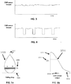
- FIG. 3 is an exemplary graph of an output of an EMR sensor 611 when no drop is detected during a period of time, according to some embodiments of the present invention.
- FIG. 4 is an exemplary graph of an output of an EMR sensor 611 when a plurality of drops is detected during a period of time, according to some embodiments of the present invention.
- FIG. 5a is an exemplary diagram of a drop 1001, according to some embodiments of the present invention.
- FIG. 5b is a graph 1010 of the output of the EMR sensor 611 resulting from the drop 1001 interfering with a portion of EMR 615, according to some embodiments of the present invention.
- Drop 1001 is displayed on a Euclidian space wherein 1002 is the vertical axis and 1003 is the horizontal axis.
- 1012 is a vertical axis which represents time
- 1013 is a horizontal axis which represents an output of EMR sensor 611.
- dx denotes a horizontal segment of drop 1001 that interferes with a portion of EMR 615 and is correlated to time segment ⁇ t i .
- time segment ⁇ t i the output of EMR sensor 611 is reduced, as shown in ⁇ v i 1014.
- FIG. 6 is an exemplary illustration of a drop partially interfering with a path of EMR, wherein each dotted line represents an EMR beam path at a sequential point in time, according to some embodiments of the current invention.
- drop 6001 falls a plurality of beams of EMR are partially interfered with over a period of time.
- FIG. 7 shows 7001, an exemplary illustration of an output of sensor 611 during a period of time, according to some embodiments of the current invention.
- the resulting output of the EMR sensor reflects the width of the horizontal segment of the drop that interferes with the EMR beam.
- the EMR source projects EMR towards the EMR sensor 611, and a falling drop partially interferes with the EMR.
- the EMR source may be positioned along the same vertical line as the EMR sensor, such that the projected EMR is reflected by the drop and the reflected EMR is received by the EMR sensor.
- FIG. 8 is a simplified longitudinal side-view and partial cross-section of exemplary EMU where an EMR source and an EMR sensor are positioned along the same vertical line, according to some embodiments of the present invention.
- an EMR source is positioned above EMR sensor 611.
- a second EMR source 1903 is positioned below EMR sensor 611.
- FIG. 9 is a schematic illustration of an exemplary computing unit 300 for calculating a volume of a drop, according to some embodiments of the present invention.
- Computing unit 300 comprises a processor 340 adapted to executing code instructions, an interface 310, a memory 330, and code instructions stored in memory 330.
- the code instructions may be functionally divided to an input module 301, an analysis module 302, and a calculating module 303.
- the data connection 620 of the EMU is connected to interface 310 which is adapted to receive analog data, analog current signals, digital data, and/or digital image data from EMR sensor 611 and/or any other EMR and/or image sensor.
- interface 310 comprises an analog to digital converter, with a sampling rate that may be set by code executed from input module 301.
- code 301 When executed, code 301 receives the digital samples from interface 310, stores the digital samples in memory 330, and adds a time stamp to the digital sample.
- Analysis module 302 contains code that when executed examines digital samples, detects a presence of a drop by a reduction in a value of the measured digital sample, and keeps a count of the number of drops detected.
- Calculating module 303 is a code that when executed receives from 302 a pointer to the digital samples in memory, and performs a calculation of a volume of the drop.
- code of calculating module 303 when executed may also perform a calculation of volume of a drop based on a digital image of the drop.
- code of calculating module 303 when executed calculates a volume of a drop based on a width of the widest horizontal segment of the drop.
- code of calculating module 303 when executed calculates a volume of a drop based on a momentum of a drop.
- the velocity of a drop is required in order to calculate a velocity for the drop.
- an EMU comprising two EMR sensors is used to measure a velocity of a drop, in the manner explained now below.
- FIG. 11a illustrates a simplified longitudinal side-view and partial cross-section of an exemplary EMU for measuring a volume of a drop with two EMR sensors, according to some embodiments of the present invention.
- a lower EMR sensor 1102 is positioned below an upper EMR sensor 1101.
- a lower EMR source 1104 is positioned below an upper EMR source 1105 to transmit EMR towards lower EMR sensor 1102.
- the falling drop path transverses a chamber which is transparent or semi transparent.
- the material of the chamber may interfere with transmission of EMR from the EMR source 1105 to EMR sensor 1101.
- EMR sensors 1101 and/or 1102 are calibrated according to the interference to EMR of the material of the chamber.
- FIG. 11b is a graphical representation of the outputs of upper EMR sensor 1101 and lower EMR sensor 1102, according to some embodiments of the present invention.
- the output of upper EMR sensor 1101 is reduced when a drop falls between upper EMR sensor 1101 and EMR source 1105.
- the output of lower EMR sensor 1102 is reduced when the same drop falls between lower EMR sensor 1102 and lower EMR source 1104.
- the drop is detected by upper EMR 1101 sensor at an initial time, and detected by the lower EMR sensor 1102 at a later time.
- the velocity of the drop may be measured by the difference between the time the upper EMR sensor detects the drop and the time the lower EMR sensor detects the drop, combined with the distance between the lower EMR sensor and the upper EMR sensor.
- a high resolution image sensor may be used in place of an EMR sensor.
- the image sensor may be selected from a group consisting of but not restricted to complementary metal oxide semiconductor (CMOS) and charge couple device (CCD), or any other type of image sensor
- CMOS complementary metal oxide semiconductor
- CCD charge couple device
- the image sensor generates a plurality of time referenced images of a drop, and the volume of the drop may be calculated from the geometry of the image, as described now below.
- FIG. 12 is an exemplary EMU for measuring a volume of a drop with an image sensor in place of an EMR sensor, according to some embodiments of the present invention.
- EMU 1200 comprises EMR source 1206 which transmits EMR 1205, image sensor 1201, drop 1202, lens 1203 and lens 1204 which focus the EMR towards image sensor 1201, and data connection 1210.
- the output of image sensor 1201 is communicated to an interface 310 of computing unit 300.
- the drop is detected by code executed from analysis module 302.
- the volume of the drop is calculated by executing code from calculating module 303 which computes a volume based on a digital image of the drop.
- the plurality of time referenced images may be used to calculate a velocity of a drop.
- Code instructions may be stored in calculating module 303 that when executed determine a location of a drop in two or more time referenced images. The code instructions when executed may combine a difference in the location of the drop in the two or more images and a difference in the time reference of the two or more images, and calculate the velocity of the drop.
- the image of a drop is used to identify the content type of the drop. For example, due to differences in fluid dynamics, a shape of a drop of water may differ from a shape and optical properties of a drop of milk.
- a plurality of exemplary images of drops comprising different types of liquid content may be stored in memory 330.
- Code instructions may be stored in calculating module 303 that when executed compare one or more of the plurality of images of the drop with each of the plurality of exemplary images, and calculate a type of fluid content of the drop.
- FIG. 19 is a flowchart of an exemplary method 1900 for calculating a content type of a drop, according to some embodiments of the present invention.
- Exemplary process 1900 may be implemented using an image sensor 1201 as depicted in EMU 1200 in FIG. 12 , and computing unit 300 in FIG. 9 .
- a plurality of exemplary images of drops of different types of fluid content is stored in memory 300 of computing unit 300.
- an image of a drop is detected by code executed from analysis module 302.
- Execution of code stored in calculation module 303 compares the image of the drop with a plurality of exemplary images of drops of different types of fluid content, selects an exemplary image that is calculated to be the same fluid content type as the drop.
- the code in analysis module 302, referred to herein as analysis code, when executed may detect the presence of one or more smaller drops, referred to herein as tails, between detected drops. Due to the fluid dynamics of many types of liquids, there is a pattern wherein one or more droplets fall shortly after a drop falls. As shown in 1113 of FIG. 11b , after a drop is detected in the output of EMR sensor 611, a tail is then detected. Analysis code 302 when executed may include minimum thresholds to filter out noise. For example, a drop with a width smaller than a certain size, and/or a number of segment few than a certain number may be categorized as noise and the volume not calculated. Analysis code 302 when executed may reduce the thresholds described above for a period of time after each detected drop in order to not ignore the expected pattern of tails.
- an EMR sensor to count the number of drops may be added to exemplary EMU 1200 in addition to an image sensor.
- FIG. 13 depicts an exemplary EMU for measuring volume of a drop with an image sensor, and counting the number of drops with an EMR sensor, according to some embodiments of the present invention.
- EMU 1300 comprises EMR source 1306 which transmits EMR 1305, lens 1303 which focus the EMR, lens 1304 which focus the EMR, beam splitter 1310 which divides EMR between EMR sensor 1311 and image sensor 1301, drop 1302, data connection 1310, and EMR cable 1311.
- the volume of a drop is calculated by computer unit 300 in the same manner as described above with EMU 1200.
- EMR cable 1311 transmits analog data to interface 310, and code executed from analysis module 302 detects a presence of a drop, and records the number of drops detected.
- FIG. 14 is a flowchart of an exemplary method 100 for calculating a volume of a drop, according to some embodiments of the present invention.
- Exemplary process 100 may be implemented using an EMU as depicted in EMU 600 in FIG. 1 and computing unit 300 in FIG. 9 .
- a drop is detected by measuring an EMR reception change at an EMU.
- EMR 615 partially interferes with EMR 615
- the partially interfered EMR 615 is digitally sampled by interface 310, and compared to a level of EMR measured when no drop is present.
- the presence of a drop is detected by a reduction in the output of the EMR sensor.
- the output of the EMR sensor 611 is sampled and converted to a digital number by code executed from input module 301 and/or by EMR sensor 611.
- Each digital number is proportional to a width of a horizontal segment of the drop.
- the digital samples are stored in memory 330.
- the sampling and converting of EMR sensor output by 102 is repeated until the drop is no longer detected.
- digital samples are collected at a rate that allows between 100 and 200 digital samples for each drop. The value of each digital sample is proportional to a width of a horizontal segment of the drop.
- processor 300 executes code instructions 303 to calculate a volume of a horizontal segment of the drop.
- the inputs for the calculation comprise the width of horizontal segment of the drop and instantaneous velocity of the drop.
- processor 300 executes code instructions 303 to calculate a volume of the drop by integrating the volumes of the horizontal segments of the drop.
- the calculation of the volume of each segment may be performed when the digital data for each segment is received.
- all the data samples for a drop are stored, and then the calculation of the volume of the segments is performed.
- Equation 1 shows an exemplary equation for volume of a horizontal segment of a drop.
- the shape of the horizontal segment approaches the shape of a cylinder.
- calculating module 104 may store code instructions to implement Equation 1.
- V i ⁇ k 4 ⁇ c ⁇ v i 2 ⁇ t i
- Equation 1 is a formula for volume of a horizontal segment of a drop and the expression for R is inserted from A into B.
- Equation 2 the equation for the volume of the drop.
- the constant k may be changed according to the selected EMR beam width.
- the EMR beam may be larger in area than the drop.
- the instantaneous velocity of the drop may be calculated by a falling body equation.
- Inputs to the falling body equation comprise the distance traveled and the gravitational constant.
- Equation 3 shows the equation for instantaneous velocity of a falling body.
- v i denotes instantaneous velocity
- g denotes gravitational constant
- d denotes distance the falling body has fallen.
- the output of EMR sensor 611 may be used to count a plurality of drops, such that a total number of drops may be calculated.
- the volume of the individual drops may be combined to calculate a total volume of liquid.
- the method described above may be used to record the volume of liquid that has been fed to a patient via a drip feeding unit.
- a device for delivering liquids for example for feeding a patient, is controlled by the method described above and execute a monitoring of volume flow of liquid in a feeding system in real time. Instructions to increase or decrease a rate of liquid flow may be calculated by combining a calculation of the total volume of liquid flowing over a time period and a desired rate of liquid flow.
- FIG. 10 is an exemplary table of data obtained using an exemplary EMU 600, according to some embodiments of the present invention.
- each row in table 200 is a series of data for a plurality of drops of liquid.
- an average of the volume of the drops in a series are computed using the method and system described above.
- an average volume of the drops in the series is measured without using the method and system described above by aggregating all the drops, measuring the total volume of the drop aggregate, and dividing by the number of drops in the series.
- the percentage of error between the computed volume 203 and actual volume 204 for all rows is less than 2%. In half of the rows, the error is less than 1%.
- the method of calculating the volume of drops is to measure the width of a plurality of horizontal segments of a drop, and combine the volume of all the horizontal segments to calculate the volume of the drop using Equation 1.
- the calculation for the volume of the drop may be constructed by collecting a plurality of exemplary data of a plurality of drops, and constructing a non linear equation to fit the exemplary data, as described below.
- the volume of a drop is calculated by a nonlinear equation derived by a curve fitting process, for example "CurveExpert Professional", “DataFit” and/or "Lab Fit”.
- the curve fitting process combines a plurality of inputs for a plurality of drops to construct an equation that when executed calculates the volume of a drop.
- FIG. 20 is an exemplary table 2000 of data for a plurality of exemplary drops, according to some embodiments of the present invention.
- each row in table 2000 is a series of data for a plurality of drops.
- the inputs to the curve fitting process comprises the maximum width of the drop, the rate of drops, the instantaneous velocity of the drop, and an independently measured volume of each drop.
- the independently measured volume of each drop is calculated by measuring the collective volume of all the drops in a series, and dividing by the number of drops in the series.
- the method of curve fitting process constructs a non linear equation.
- the nonlinear behavior of the data of table 2000 presented graphically in FIG. 21 which is a graphical representation of data from table 2000 that plots the width of a drop on the horizontal axis and the amount of cubic centimeter (cc) in a drop on the vertical axis, according to some embodiments of the present invention.
- FIG. 22 is a graphical representation of non linear nature of the data from table 2000 that plots the drop velocity on the horizontal axis and the amount of cc in a drop on the vertical axis, according to some embodiments of the present invention.
- FIG. 23 is a graphical representation of non linear nature of the data from table 2000 that plots the square of the measured output of an EMR sensor when a drop is detected on the horizontal axis and the amount of cc in a drop on the vertical axis, according to some embodiments of the present invention.
- the curve fitting process may construct a nonlinear equation to calculate a volume of a drop based on the data from table 20.
- the nonlinear equation calculates the volume of drops based on the input of a single width of the widest horizontal segment of a drop, and drop velocity.
- Equation 4 is an exemplary equation to calculate a volume of a drop constructed by curve fitting process, according to some embodiments of the present invention.
- Y A ⁇ e B X 2 + C ⁇ X 1 + D ⁇ X 2
- a volume of a drop may be calculated by measuring an EMR beam that the drop partially interferes with.
- the volume of a drop may be measured using an EMU that has a protrusion that is deflected by the falling drop.
- a volume of a drop may be calculated by a method comprising deflecting a semi elastic protrusion, referred to herein as a plank, according to some examples not part of the present invention.
- a plank is fixedly placed in the path of a drop. When the drop strikes the plank, the plank is deflected downwards. Within limited deflection range, the deflection of the plank is linearly proportional to the momentum of the drop, wherein momentum equals mass times velocity.
- Volume of a liquid may be calculated by combining a specific gravity of the liquid with a mass of the liquid. A beam of EMR is partially interfered when the plank is deflected may be used to calculate the volume of the drop in a manner similar to EMU 600.
- FIG. 15a illustrates a simplified longitudinal side-view and partial cross-section of an exemplary EMU for measuring a volume of a drop by deforming a plank, according to some examples not part of the present invention.
- EMU 1500 is equipped with plank 1501, but is otherwise similar to EMU 300 in all regards.
- plank 1502 is fixedly positioned in the path of drop 1501.
- FIG. 15b shows EMU 1500 when plank 1502 is struck by drop 1501 and is deflected into the path of EMR beam 1503, according to some examples not part of the present invention.
- EMR source 1510 and EMR sensor 1511 are Not shown in FIG. 15a.
- FIG. 15c illustrates a frontal view of EMU 1500.
- EMR source 1511 projects a beam of EMR 1503 towards EMR sensor 1512, according to some examples not part of the present invention.
- Data connection 1520 is shown, not shown in FIG. 15c is plank 1501.
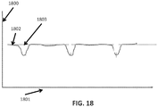
- FIG. 18 is an exemplary graph of an output of EMR sensor 1512, according to some examples not part of the present invention.
- 1800 is a vertical axis which represents a level of an output of 1512
- 1801 is a horizontal axis which represents the time axis.
- the output of EMR sensor 1512 is at a higher level at 1802 when plank 1502 is not deflected, and the output of 1512 goes down as shown in 1803 when a drop partially interferes with EMR 1503.
- An output of EMR sensor 1311 is connected to interface 310 of computing unit 300.
- Computing unit 300 operates substantially as described above.
- Memory module 301 and analysis module 302 function as described above.
- Calculating module 303 stores code instructions that when executed search for the digital sample from a drop with the lowest value, indicating maximum deflection, which is normalized to an amount of momentum.
- An instantaneous velocity of the drop is calculated using the falling body equation as described above, or the instantaneous velocity is measured using EMU 1100 as described above.
- Code instructions when executed calculate the mass of the drop by combining instantaneous velocity with momentum measured by plank deflection.
- the formula stating momentum equals mass times velocity is used to calculate the mass of the drop, and the volume may be derived from the mass for each type of liquid.
- a flow rate of drops may be calculated by Equation 5.
- m ⁇ m d ⁇ f d
- a piezoelectric sensor is attached to plank 1502, such that when a drop deflects plank 1502, the piezoelectric sensor is deformed.
- Volume of drops in EMU 1500 may be calculated by the output of the piezoelectric sensor which is attached to interface 310 in a manner similar to EMU 1500.
- FIG. 16 illustrates a simplified longitudinal side-view and partial cross-section of exemplary EMU 1500 for calculating a volume of drops with a piezoelectric sensor 1601, according to some embodiments of the present invention.
- Piezoelectric sensor 1601 is attached to plank 1502, such that when a drop deflects plank 1502 piezoelectric sensor 1601 is compressed.
- An output of 1601 is connected to interface 310.
- the output of 1601 is proportional to the momentum of a drop.
- Computing unit 300 calculates the volume of a drop in a manner similar to when attached to EMU 1500 above.
- a coil is positioned proximal to plank 1502, and a magnet is attached to plank 1502, such that when a drop deflects plank 1502, the distance between the magnet and the coil is changed, and a current in induced in the coil.
- Volume of drops in EMU 1500 may be calculated by the output of the coil.
- FIG. 17 illustrates a simplified longitudinal side-view and partial cross-section of exemplary EMU 1500 for calculating a volume of drops with a magnet and a coil, according to some examples not part of the present invention.
- a magnet 1701 is attached to plank 1502 and a coil 1703 is located proximal to magnet 1501.
- An output of 1701 is connected to interface 310.
- the output of 1701 is proportional to the mass of a drop.
- Computing unit 300 calculates the volume of a drop in a manner similar to when attached to plank EMU 1500.
- composition or method may include additional ingredients and/or steps, but only if the additional ingredients and/or steps do not materially alter the basic and novel characteristics of the claimed composition or method.
- a compound or “at least one compound” may include a plurality of compounds, including mixtures thereof.
Description
- The present invention, in some embodiments thereof, relates to a method of calculating volume of falling liquid drops and, more specifically, but not exclusively, to calculating volume of a drop based on output of electromagnetic radiation sensors that detects the drop.
- Control of flow rates of liquids is essential in a variety of applications, including automatic feeding of patients via drip tubes. Flow of liquids may be accomplished by a gravity bag, or a peristaltic pump. A person may monitor whether the liquid is flowing by observing a transparent drip apparatus. However, visual monitoring is strictly qualitative, and does not supply information on flow rate or volume dispensed over time. There exist a need for an independent flow sensor that will provide real time flow quantitative data as well observable qualitative information, where the sensor that does not coming into contact with the feed thus does not require cleaning and sterilization.
- Japanese application
JPH04 51963 A - The present invention provides a method as laid out in
independent claim 1 and a system as laid out in independent claim 8. Optional features concerning the method and the system are laid out in dependent claims 2-7 and in dependent claims 9-15, respectively. - Unless otherwise defined, all technical and/or scientific terms used herein have the same meaning as commonly understood by one of ordinary skill in the art to which the invention pertains. Although methods and materials similar or equivalent to those described herein may be used in the practice or testing of embodiments of the invention, exemplary methods and/or materials are described below. In case of conflict, the patent specification, including definitions, will control. In addition, the materials, methods, and examples are illustrative only and are not intended to be necessarily limiting.
- Some embodiments of the invention are herein described, by way of example only, with reference to the accompanying drawings. With specific reference now to the drawings in detail, it is stressed that the particulars shown are by way of example and for purposes of illustrative discussion of embodiments of the invention. In this regard, the description taken with the drawings makes apparent to those skilled in the art how embodiments of the invention may be practiced.
- In the drawings:
-
FIG. 1 is a schematic illustration of an exemplary component of a system for calculating a volume of a drop of liquid, according to some embodiments of the present invention; -
FIG. 2 is a schematic illustration of an exemplary component of a system for calculating a volume of a drop of liquid, with a drop of liquid interfering with a beam of electromagnetic radiation according to some embodiments of the present invention; -
FIG. 3 is an exemplary graph of an output of an electromagnetic radiation sensor during a time period when no drops are detected, according to some embodiments of the present invention; -
FIG. 4 is an exemplary graph of an output of an electromagnetic radiation sensor during a time period when a plurality of drops is detected, according to some embodiments of the present invention; -
FIG. 5a which is an exemplary diagram of a drop in a Euclidean plane, according to some embodiments of the present invention; -
FIG. 5b is a graph of an output of an electromagnetic radiation sensor when a drop is detected, according to some embodiments of the present invention; -
FIG. 6 is an exemplary illustration of a drop partially interfering with a path of EMR, wherein each dotted line represents an EMR beam path at a sequential point in time, according to some embodiments of the current invention; -
FIG. 7 is an exemplary illustration of a time sequence of a falling drop interfering with electromagnetic radiation beams during a period of time, according to some embodiments of the current invention; -
FIG. 8 illustrates a simplified longitudinal side-view and partial cross-section of an exemplary electromagnetic radiation measurement unit for measuring a volume of a drop where an electromagnetic radiation source and an electromagnetic radiation sensor are positioned along the same vertical line, according to some embodiments of the present invention; -
FIG. 9 is a schematic illustration of an exemplary element of a system for calculating a volume of a drop of liquid, according to some embodiments of the present invention; -
FIG. 10 is an exemplary table of data obtained from an exemplary electromagnetic radiation measurement unit for calculating a volume of a drop of liquid, according to some embodiments of the present invention; -
FIG. 11a illustrates a simplified longitudinal side-view and partial cross-section of an exemplary electromagnetic radiation measurement unit for measuring a volume of a drop with two electromagnetic radiation sensors, according to some embodiments of the present invention; -
FIG. 11b is a graphical representation of the outputs of upper electromagnetic radiation sensor and lower electromagnetic radiation sensor, according to some embodiments of the present invention; -
FIG. 12 is an exemplary electromagnetic radiation measuring unit for measuring a volume of a drop with an image sensor, according to some embodiments of the present invention; -
FIG. 13 is an exemplary electromagnetic radiation measurement unit for measuring a volume of a drop with an image sensor, and counting the number of drops with an electromagnetic radiation sensor, according to some embodiments of the present invention; -
FIG. 14 is a flowchart of an exemplary method for calculating a volume of a drop of liquid, according to some embodiments of the present invention; -
FIG. 15a is a simplified longitudinal side-view and partial cross-section of an exemplary electromagnetic radiation measurement unit for measuring a volume of a drop by deforming a plank, according to some examples not part of the present invention; -
FIG. 15b is a simplified longitudinal side-view and partial cross-section of an exemplary electromagnetic radiation measurement unit for measuring a volume of a drop by deforming a plank when the plank is struck by the drop, in some examples not part of the present invention; -
FIG. 15c is a simplified frontal view of an exemplary electromagnetic radiation measurement unit for measuring a volume of a drop by deforming a plank, in some examples not part of the present invention; -
FIG. 16 is a simplified longitudinal side-view and partial cross-section of an exemplary electromagnetic radiation measurement unit for calculating a volume of drops with a piezoelectric sensor, according to some examples not part of the present invention; -
FIG. 17 is a simplified longitudinal side-view and partial cross-section of an exemplary electromagnetic radiation measurement unit for calculating a volume of drops with a magnet and a coil, according to some examples not part of the present invention; -
FIG. 18 is an exemplary graph of an output of an electromagnetic radiation sensor of an exemplary electromagnetic radiation measurement unit for measuring a volume of a drop by deforming a plank according to some examples not part of the present invention; -
FIG. 19 is a flowchart of an exemplary method for calculating a content type of a drop of liquid, according to some embodiments of the present invention; -
FIG. 20 is an exemplary table of data obtained from an exemplary electromagnetic radiation measurement unit for calculating a volume of a drop of liquid, according to some embodiments of the present invention; -
FIG. 21 is a graphical representation of drop width data from table 2000, according to some embodiments of the present invention; -
FIG. 22 is a graphical representation of drop velocity data from table 2000, according to some embodiments of the present invention; and -
FIG. 23 is a graphical representation of squared output of an EMR sensor data from table 2000, according to some embodiments of the present invention. - The present invention, in some embodiments thereof, relates to a method of calculating a volume of a falling drop of liquid, referred to herein as a drop, and more specifically but not exclusively, to calculating a volume of a drop based on an output of electromagnetic radiation (EMR) sensors that detect the drop. A volume of fluid of all drops may be calculated by combining a count of the drops with the volume of the drops.
- Measurement of volume of flow of liquids in a liquid drip system presents operational and technical challenges. The measurement apparatus ideally should be isolated from the liquid, in order to eliminate the need to clean and sterilize the apparatus. Existing solutions rely on estimating flow based on counting drops, but this system lacks accuracy due to variations in drop size and dripping rate. Solutions for measuring flow employ ultra sound sensors or thermal diffusion sensors attached to a pump. Such solutions do not measure drops, only continuous flow. According to some embodiments of the present invention, there are provided systems and methods for calculating a volume of individual drops, and cumulative flow volume of the liquid over time, using apparatus that is isolated from the liquid.
- The present invention, in some embodiments thereof, is measuring a volume of a drop by summing volumes of a plurality of horizontal planar segments of the drop. The volume of each horizontal planar segment of a drop is calculated by measuring the EMR captured in a restricted horizontal planar area during a sequence of time intervals. As the drop falls, in each time interval a different horizontal segment of the drop interferes with a portion of EMR in the restricted horizontal planar area. The width of the horizontal segment of the drop is proportional to the amount of EMR that is interfered. The volume of the horizontal segment may be calculated when the width of the segment and the velocity of the segment are known.
- The present invention, in some embodiments thereof, is based on a drop of liquid interfering with a preferably a collimated beam of EMR aimed at an EMR sensor. The output of the EMR sensor is proportional to the amount of EMR intercepted, such that the presence of the drop in front of the EMR sensor or at the EMR path ending at the EMR sensor changes the EMR received by the EMR sensor. An output of the EMR sensor is digitally sampled at a rate that produces a plurality of samples for each drop, wherein a value of each digital sample is proportional to a width of a horizontal segment of the drop. A velocity of the drop is calculated using a falling body equation. An equation using the width of the drop and the velocity of the drop as inputs is then used to calculate a volume of each segment of the drop. The volume of the drop is calculated by a sum the volumes of the segments.
- The EMR may be for example a collimated beam of visible light. The falling drop may interfere with the EMR by blocking, partially blocking, absorbing, reflecting, diffracting and/or deflecting the EMR.
- Before explaining at least one embodiment of the invention in detail, it is to be understood that the invention is not necessarily limited in its application to the details of construction and the arrangement of the components and/or methods set forth in the following description and/or illustrated in the drawings and/or the Examples. The invention is capable of other embodiments or of being practiced or carried out in various ways.
- The present invention may be a system, a method, and/or a computer program product. The computer program product may include a computer readable storage medium (or media) having computer readable program instructions thereon for causing a processor to carry out aspects of the present invention.
- The computer readable storage medium may be a tangible device that may retain and store instructions for use by an instruction execution device. The computer readable storage medium may be, for example, but is not limited to, an electronic storage device, a magnetic storage device, an optical storage device, an electromagnetic storage device, a semiconductor storage device, or any suitable combination of the foregoing.
- Computer readable program instructions described herein may be downloaded to respective computing/processing devices from a computer readable storage medium or to an external computer or external storage device via a network, for example, the Internet, a local area network, a wide area network and/or a wireless network.
- The computer readable program instructions may execute entirely on the user's computer, partly on the user's computer, as a stand-alone software package, partly on the user's computer and partly on a remote computer or entirely on the remote computer or server. In the latter scenario, the remote computer may be connected to the user's computer through any type of network, including a local area network (LAN) or a wide area network (WAN), or the connection may be made to an external computer (for example, through the Internet using an Internet Service Provider). In some embodiments, electronic circuitry including, for example, programmable logic circuitry, field-programmable gate arrays (FPGA), or programmable logic arrays (PLA) may execute the computer readable program instructions by utilizing state information of the computer readable program instructions to personalize the electronic circuitry, in order to perform aspects of the present invention.
- Aspects of the present invention are described herein with reference to flowchart illustrations and/or block diagrams of methods, apparatus (systems), and computer program products according to embodiments of the invention. It will be understood that each block of the flowchart illustrations and/or block diagrams, and combinations of blocks in the flowchart illustrations and/or block diagrams, may be implemented by computer readable program instructions.
- The flowchart and block diagrams in the Figures illustrate the architecture, functionality, and operation of possible implementations of systems, methods, and computer program products according to various embodiments of the present invention. In this regard, each block in the flowchart or block diagrams may represent a module, segment, or portion of instructions, which comprises one or more executable instructions for implementing the specified logical function(s). In some alternative implementations, the functions noted in the block may occur out of the order noted in the figures. For example, two blocks shown in succession may, in fact, be executed substantially concurrently, or the blocks may sometimes be executed in the reverse order, depending upon the functionality involved. It will also be noted that each block of the block diagrams and/or flowchart illustration, and combinations of blocks in the block diagrams and/or flowchart illustration, may be implemented by special purpose hardware-based systems that perform the specified functions or acts or carry out combinations of special purpose hardware and computer instructions.
- The present invention, in some embodiments thereof, comprises methods and systems for measuring the volume of a falling liquid drop and counting the drops over a period of time. The system comprises two components, an EMR measurement unit chamber, referred to herein as EMU, and a computing unit. The EMU and the computing unit may communicate with one another using a wired data connection and/or via a wireless data connection, referred to herein as a data connection.
- The first component of the system, EMU, projects EMR, for example a beam of light, towards a falling liquid drop referred to herein as a drop, measures an interference in the EMR caused by the drop, and communicates the measurement via a data connection. The second component of the system is a computing unit, which is capable of receiving data signals from the EMU via the data connection, accumulates measurement data related to a single drop, combines the measurement data with the instantaneous velocity of the drop, and calculates a volume of the drop.
- Reference is now made to
FIG. 1 which is an exemplary illustration ofEMU 600, according to some embodiments of the present invention.EMU 600 measures a width of a plurality of horizontal planar segments of a drop, which is communicated to a computing unit which calculates a volume of each segment and then computes a volume of the entire drop. The EMU comprises anEMR source 612, anEMR sensor 611, and adata connection 620.EMR source 612 emits a beam ofEMR 615 towardsEMR sensor 611. Shown in 615 is an EMR path betweenEMR source 612 andEMR sensor 611. Reference is now also made toFIG. 2 , which is an exemplary illustration ofEMU 600 with adrop 618 interfering with a portion ofEMR 615 along the EMR path, according to some embodiments of the present invention. The amount of EMR interfered with by a horizontal segment of a drop is proportional to the width of the segment. The drop segment obscures a portion of the EMR proportional to the width thus effecting the photo sensor output signal. - The
EMR source 612 projects an EMR beam collimated and focused on a restricted horizontal planar segment, as shown bylens 616 andlens 617. The collimated EMR and restricted horizontal path of the beam increases the accuracy of the proportionality of the output of the EMR sensor to the width of a horizontal segment of a drop. - Optionally,
lens 616 andlens 617 focus theEMR 615 along an axis perpendicular to the reception plane ofEMR sensor 611. - Reference is now also made to
FIG. 3 which is an exemplary graph of an output of anEMR sensor 611 when no drop is detected during a period of time, according to some embodiments of the present invention. Reference is now also made toFIG. 4 which is an exemplary graph of an output of anEMR sensor 611 when a plurality of drops is detected during a period of time, according to some embodiments of the present invention. - Reference is now also made to
FIG. 5a which is an exemplary diagram of adrop 1001, according to some embodiments of the present invention. Reference is now also made toFIG. 5b which is agraph 1010 of the output of theEMR sensor 611 resulting from thedrop 1001 interfering with a portion ofEMR 615, according to some embodiments of the present invention.Drop 1001 is displayed on a Euclidian space wherein 1002 is the vertical axis and 1003 is the horizontal axis. As shown ingraph EMR sensor 611. As shown indx 1005, dx denotes a horizontal segment ofdrop 1001 that interferes with a portion ofEMR 615 and is correlated to time segment Δti. During time segment Δti the output ofEMR sensor 611 is reduced, as shown inΔv i 1014. - Reference is now also made to
FIG. 6 , which is an exemplary illustration of a drop partially interfering with a path of EMR, wherein each dotted line represents an EMR beam path at a sequential point in time, according to some embodiments of the current invention. Asdrop 6001 falls a plurality of beams of EMR are partially interfered with over a period of time. - As described above, when the EMR beam is collimated and restricted to a horizontal planar segment, as
drop 6001 falls at any given point in time only a restricted horizontal segment of the drop is interfering with EMR projected towardsEMR sensor 611. As shown in t-1, an exemplary beam of EMR is interfered with by a horizontal segment ofdrop 6001 at a specific point in time. At a later point in time, t-2 is interfered with by a different horizontal segment of the drop. - Reference is now also made to
FIG. 7 , which shows 7001, an exemplary illustration of an output ofsensor 611 during a period of time, according to some embodiments of the current invention. As shown in 7002, as each different horizontal segment of the drop interferes with a different beam of EMR at a different time, the resulting output of the EMR sensor reflects the width of the horizontal segment of the drop that interferes with the EMR beam. - As described above in 612 the EMR source projects EMR towards the
EMR sensor 611, and a falling drop partially interferes with the EMR. Optionally, the EMR source may be positioned along the same vertical line as the EMR sensor, such that the projected EMR is reflected by the drop and the reflected EMR is received by the EMR sensor. - For example,
FIG. 8 is a simplified longitudinal side-view and partial cross-section of exemplary EMU where an EMR source and an EMR sensor are positioned along the same vertical line, according to some embodiments of the present invention. As shown in 1901, an EMR source is positioned aboveEMR sensor 611. Optionally asecond EMR source 1903 is positioned belowEMR sensor 611. - As mentioned above, the second component of the system to measure a volume of a drop is a computing unit which is connected to the EMU by
data connection 620. For exampleFIG. 9 is a schematic illustration of anexemplary computing unit 300 for calculating a volume of a drop, according to some embodiments of the present invention.Computing unit 300 comprises aprocessor 340 adapted to executing code instructions, aninterface 310, amemory 330, and code instructions stored inmemory 330. The code instructions may be functionally divided to aninput module 301, ananalysis module 302, and a calculatingmodule 303. Thedata connection 620 of the EMU is connected to interface 310 which is adapted to receive analog data, analog current signals, digital data, and/or digital image data fromEMR sensor 611 and/or any other EMR and/or image sensor. When the output ofEMR sensor 611 is analog,interface 310 comprises an analog to digital converter, with a sampling rate that may be set by code executed frominput module 301. - When executed,
code 301 receives the digital samples frominterface 310, stores the digital samples inmemory 330, and adds a time stamp to the digital sample.Analysis module 302 contains code that when executed examines digital samples, detects a presence of a drop by a reduction in a value of the measured digital sample, and keeps a count of the number of drops detected.Calculating module 303 is a code that when executed receives from 302 a pointer to the digital samples in memory, and performs a calculation of a volume of the drop. - Optionally code of calculating
module 303 when executed may also perform a calculation of volume of a drop based on a digital image of the drop. Optionally code of calculatingmodule 303 when executed calculates a volume of a drop based on a width of the widest horizontal segment of the drop. Optionally, code of calculatingmodule 303 when executed calculates a volume of a drop based on a momentum of a drop. - As mention above, the velocity of a drop is required in order to calculate a velocity for the drop. Optionally, an EMU comprising two EMR sensors is used to measure a velocity of a drop, in the manner explained now below.
- For example,
FIG. 11a illustrates a simplified longitudinal side-view and partial cross-section of an exemplary EMU for measuring a volume of a drop with two EMR sensors, according to some embodiments of the present invention. Alower EMR sensor 1102 is positioned below anupper EMR sensor 1101. Optionally, a lower EMR source 1104 is positioned below anupper EMR source 1105 to transmit EMR towardslower EMR sensor 1102. - As seen in 1150 in
FIG. 11a , the falling drop path transverses a chamber which is transparent or semi transparent. The material of the chamber may interfere with transmission of EMR from theEMR source 1105 toEMR sensor 1101.EMR sensors 1101 and/or 1102 are calibrated according to the interference to EMR of the material of the chamber. - For example
FIG. 11b is a graphical representation of the outputs ofupper EMR sensor 1101 andlower EMR sensor 1102, according to some embodiments of the present invention. As shown in 1111 the output ofupper EMR sensor 1101 is reduced when a drop falls betweenupper EMR sensor 1101 andEMR source 1105. As shown in 1112 the output oflower EMR sensor 1102 is reduced when the same drop falls betweenlower EMR sensor 1102 and lower EMR source 1104. The drop is detected byupper EMR 1101 sensor at an initial time, and detected by thelower EMR sensor 1102 at a later time. The velocity of the drop may be measured by the difference between the time the upper EMR sensor detects the drop and the time the lower EMR sensor detects the drop, combined with the distance between the lower EMR sensor and the upper EMR sensor. - Optionally, a high resolution image sensor may be used in place of an EMR sensor. The image sensor may be selected from a group consisting of but not restricted to complementary metal oxide semiconductor (CMOS) and charge couple device (CCD), or any other type of image sensor The image sensor generates a plurality of time referenced images of a drop, and the volume of the drop may be calculated from the geometry of the image, as described now below. For example,
FIG. 12 is an exemplary EMU for measuring a volume of a drop with an image sensor in place of an EMR sensor, according to some embodiments of the present invention.EMU 1200 comprisesEMR source 1206 which transmitsEMR 1205,image sensor 1201,drop 1202,lens 1203 andlens 1204 which focus the EMR towardsimage sensor 1201, anddata connection 1210. The output ofimage sensor 1201 is communicated to aninterface 310 ofcomputing unit 300. The drop is detected by code executed fromanalysis module 302. The volume of the drop is calculated by executing code from calculatingmodule 303 which computes a volume based on a digital image of the drop. - Optionally the plurality of time referenced images may be used to calculate a velocity of a drop. Code instructions may be stored in calculating
module 303 that when executed determine a location of a drop in two or more time referenced images. The code instructions when executed may combine a difference in the location of the drop in the two or more images and a difference in the time reference of the two or more images, and calculate the velocity of the drop. - The image of a drop is used to identify the content type of the drop. For example, due to differences in fluid dynamics, a shape of a drop of water may differ from a shape and optical properties of a drop of milk. To enable a calculation of fluid type, a plurality of exemplary images of drops comprising different types of liquid content may be stored in
memory 330. Code instructions may be stored in calculatingmodule 303 that when executed compare one or more of the plurality of images of the drop with each of the plurality of exemplary images, and calculate a type of fluid content of the drop. - For example,
FIG. 19 is a flowchart of anexemplary method 1900 for calculating a content type of a drop, according to some embodiments of the present invention.Exemplary process 1900 may be implemented using animage sensor 1201 as depicted inEMU 1200 inFIG. 12 , andcomputing unit 300 inFIG. 9 . As shown in 101 a plurality of exemplary images of drops of different types of fluid content is stored inmemory 300 ofcomputing unit 300. As shown in 102, an image of a drop is detected by code executed fromanalysis module 302. Execution of code stored incalculation module 303 compares the image of the drop with a plurality of exemplary images of drops of different types of fluid content, selects an exemplary image that is calculated to be the same fluid content type as the drop. - Optionally, the code in
analysis module 302, referred to herein as analysis code, when executed may detect the presence of one or more smaller drops, referred to herein as tails, between detected drops. Due to the fluid dynamics of many types of liquids, there is a pattern wherein one or more droplets fall shortly after a drop falls. As shown in 1113 ofFIG. 11b , after a drop is detected in the output ofEMR sensor 611, a tail is then detected.Analysis code 302 when executed may include minimum thresholds to filter out noise. For example, a drop with a width smaller than a certain size, and/or a number of segment few than a certain number may be categorized as noise and the volume not calculated.Analysis code 302 when executed may reduce the thresholds described above for a period of time after each detected drop in order to not ignore the expected pattern of tails. - Optionally, an EMR sensor to count the number of drops may be added to
exemplary EMU 1200 in addition to an image sensor. For example,FIG. 13 depicts an exemplary EMU for measuring volume of a drop with an image sensor, and counting the number of drops with an EMR sensor, according to some embodiments of the present invention.EMU 1300 comprisesEMR source 1306 which transmitsEMR 1305,lens 1303 which focus the EMR,lens 1304 which focus the EMR,beam splitter 1310 which divides EMR betweenEMR sensor 1311 andimage sensor 1301,drop 1302,data connection 1310, andEMR cable 1311. The volume of a drop is calculated bycomputer unit 300 in the same manner as described above withEMU 1200. In addition,EMR cable 1311 transmits analog data to interface 310, and code executed fromanalysis module 302 detects a presence of a drop, and records the number of drops detected. - As described above, the system to calculate a volume of a drop comprises an EMU and a computing unit. For example,
FIG. 14 is a flowchart of anexemplary method 100 for calculating a volume of a drop, according to some embodiments of the present invention.Exemplary process 100 may be implemented using an EMU as depicted inEMU 600 inFIG. 1 andcomputing unit 300 inFIG. 9 . As shown in 101 a drop is detected by measuring an EMR reception change at an EMU. For example, when a drop partially interferes withEMR 615, and the partially interferedEMR 615 is digitally sampled byinterface 310, and compared to a level of EMR measured when no drop is present. The presence of a drop is detected by a reduction in the output of the EMR sensor. - As shown in 102, the output of the
EMR sensor 611 is sampled and converted to a digital number by code executed frominput module 301 and/or byEMR sensor 611. Each digital number is proportional to a width of a horizontal segment of the drop. As the sampling rate increases, the height of the horizontal segment decreases, and the shape of the horizontal segment approaches the shape of a cylinder. The digital samples are stored inmemory 330. The sampling and converting of EMR sensor output by 102 is repeated until the drop is no longer detected. As the drop falls through the path of theEMR beam 615, digital samples are collected at a rate that allows between 100 and 200 digital samples for each drop. The value of each digital sample is proportional to a width of a horizontal segment of the drop. - As shown in 103,
processor 300 executescode instructions 303 to calculate a volume of a horizontal segment of the drop. The inputs for the calculation comprise the width of horizontal segment of the drop and instantaneous velocity of the drop. As shown in 104,processor 300 executescode instructions 303 to calculate a volume of the drop by integrating the volumes of the horizontal segments of the drop. - Optionally, the calculation of the volume of each segment may be performed when the digital data for each segment is received. Optionally all the data samples for a drop are stored, and then the calculation of the volume of the segments is performed.
- The equations for the calculation of the volume of a horizontal drop segment and the calculation for the volume of a drop are now shown below.
Equation 1 shows an exemplary equation for volume of a horizontal segment of a drop. The shape of the horizontal segment approaches the shape of a cylinder. For example, calculatingmodule 104 may store code instructions to implementEquation 1.
- Note that
Equation 1 is derived in the following manner:
- [A]


- xi denotes height of a drop segment;
- c denotes instantaneous velocity of a drop;
- t i denotes time between digital samples;
- Ai denotes area of a drop segment;
- vi denotes output of an EMR sensor during a digital sample;
- Ri denotes a radius of a drop segment;
- Vi denotes volume of a drop segment;
- V denotes volume of a drop;
- i denotes index of drop segments; and
- n denotes total number of segments comprising a drop.
- k denotes a constant to be calculated once depending on the optics geometry
- Note that
Equation 1 is a formula for volume of a horizontal segment of a drop and the expression for R is inserted from A into B. - By integrating
Equation 1 for all segments of the drop, we deriveequation 2, the equation for the volume of the drop.
- Optionally the EMR beam may be larger in area than the drop.
- Optionally the instantaneous velocity of the drop may be calculated by a falling body equation. Inputs to the falling body equation comprise the distance traveled and the gravitational constant. Equation 3 shows the equation for instantaneous velocity of a falling body.

- Where vi denotes instantaneous velocity, g denotes gravitational constant and d denotes distance the falling body has fallen.
- Optionally the output of
EMR sensor 611 may be used to count a plurality of drops, such that a total number of drops may be calculated. Optionally, the volume of the individual drops may be combined to calculate a total volume of liquid. For example, in a liquid feeding device, the method described above may be used to record the volume of liquid that has been fed to a patient via a drip feeding unit. - A device for delivering liquids, for example for feeding a patient, is controlled by the method described above and execute a monitoring of volume flow of liquid in a feeding system in real time. Instructions to increase or decrease a rate of liquid flow may be calculated by combining a calculation of the total volume of liquid flowing over a time period and a desired rate of liquid flow.
- The method and system described above calculate volume of a drop. The accuracy of the method and system are described now below. For example
FIG. 10 is an exemplary table of data obtained using anexemplary EMU 600, according to some embodiments of the present invention. As shown in 201, each row in table 200 is a series of data for a plurality of drops of liquid. As shown in 203, an average of the volume of the drops in a series are computed using the method and system described above. As shown in 204 an average volume of the drops in the series is measured without using the method and system described above by aggregating all the drops, measuring the total volume of the drop aggregate, and dividing by the number of drops in the series. - As shown in 202, the percentage of error between the
computed volume 203 andactual volume 204 for all rows is less than 2%. In half of the rows, the error is less than 1%. - As described above, the method of calculating the volume of drops is to measure the width of a plurality of horizontal segments of a drop, and combine the volume of all the horizontal segments to calculate the volume of the
drop using Equation 1. - Optionally, the calculation for the volume of the drop may be constructed by collecting a plurality of exemplary data of a plurality of drops, and constructing a non linear equation to fit the exemplary data, as described below.
- Optionally, the volume of a drop is calculated by a nonlinear equation derived by a curve fitting process, for example "CurveExpert Professional", "DataFit" and/or "Lab Fit". The curve fitting process combines a plurality of inputs for a plurality of drops to construct an equation that when executed calculates the volume of a drop.
- As described above, the curve fitting process requires a plurality of data for a plurality of drops. For example
FIG. 20 is an exemplary table 2000 of data for a plurality of exemplary drops, according to some embodiments of the present invention. As shown in 2001, each row in table 2000 is a series of data for a plurality of drops. The inputs to the curve fitting process comprises the maximum width of the drop, the rate of drops, the instantaneous velocity of the drop, and an independently measured volume of each drop. The independently measured volume of each drop is calculated by measuring the collective volume of all the drops in a series, and dividing by the number of drops in the series. - The method of curve fitting process constructs a non linear equation. The nonlinear behavior of the data of table 2000 presented graphically in
FIG. 21 which is a graphical representation of data from table 2000 that plots the width of a drop on the horizontal axis and the amount of cubic centimeter (cc) in a drop on the vertical axis, according to some embodiments of the present invention. - Reference is now also made to
FIG. 22 which is a graphical representation of non linear nature of the data from table 2000 that plots the drop velocity on the horizontal axis and the amount of cc in a drop on the vertical axis, according to some embodiments of the present invention. - Reference is now also made to
FIG. 23 which is a graphical representation of non linear nature of the data from table 2000 that plots the square of the measured output of an EMR sensor when a drop is detected on the horizontal axis and the amount of cc in a drop on the vertical axis, according to some embodiments of the present invention. - The curve fitting process may construct a nonlinear equation to calculate a volume of a drop based on the data from table 20. The nonlinear equation calculates the volume of drops based on the input of a single width of the widest horizontal segment of a drop, and drop velocity. Equation 4 is an exemplary equation to calculate a volume of a drop constructed by curve fitting process, according to some embodiments of the present invention.

- Y denotes volume of a drop;
- X1 denotes widest width of drop;
- X2 denotes drop velocity; and
- A, B, C, D = constants
- In the system described above, a volume of a drop may be calculated by measuring an EMR beam that the drop partially interferes with. Alternatively, the volume of a drop may be measured using an EMU that has a protrusion that is deflected by the falling drop. A plurality of methods of measuring the deflection of the protrusion are now described below.
- A volume of a drop may be calculated by a method comprising deflecting a semi elastic protrusion, referred to herein as a plank, according to some examples not part of the present invention. A plank is fixedly placed in the path of a drop. When the drop strikes the plank, the plank is deflected downwards. Within limited deflection range, the deflection of the plank is linearly proportional to the momentum of the drop, wherein momentum equals mass times velocity. Volume of a liquid may be calculated by combining a specific gravity of the liquid with a mass of the liquid. A beam of EMR is partially interfered when the plank is deflected may be used to calculate the volume of the drop in a manner similar to
EMU 600. - Reference is now made to
FIG. 15a which illustrates a simplified longitudinal side-view and partial cross-section of an exemplary EMU for measuring a volume of a drop by deforming a plank, according to some examples not part of the present invention.EMU 1500 is equipped withplank 1501, but is otherwise similar toEMU 300 in all regards. As shown inEMU 1500plank 1502 is fixedly positioned in the path ofdrop 1501. - Reference is now made to
FIG. 15b which showsEMU 1500 whenplank 1502 is struck bydrop 1501 and is deflected into the path ofEMR beam 1503, according to some examples not part of the present invention. Not shown inFIG. 15a is EMR source 1510 andEMR sensor 1511. - Reference is now made to
FIG. 15c which illustrates a frontal view ofEMU 1500. As shown in 1500,EMR source 1511 projects a beam ofEMR 1503 towardsEMR sensor 1512, according to some examples not part of the present invention.Data connection 1520 is shown, not shown inFIG. 15c isplank 1501. - Reference is now made to
FIG. 18 which is an exemplary graph of an output ofEMR sensor 1512, according to some examples not part of the present invention. 1800 is a vertical axis which represents a level of an output of 1512, and 1801 is a horizontal axis which represents the time axis. The output ofEMR sensor 1512 is at a higher level at 1802 whenplank 1502 is not deflected, and the output of 1512 goes down as shown in 1803 when a drop partially interferes withEMR 1503. - An output of
EMR sensor 1311 is connected to interface 310 ofcomputing unit 300.Computing unit 300 operates substantially as described above.Memory module 301 andanalysis module 302 function as described above.Calculating module 303 stores code instructions that when executed search for the digital sample from a drop with the lowest value, indicating maximum deflection, which is normalized to an amount of momentum. An instantaneous velocity of the drop is calculated using the falling body equation as described above, or the instantaneous velocity is measured usingEMU 1100 as described above. Code instructions when executed calculate the mass of the drop by combining instantaneous velocity with momentum measured by plank deflection. The formula stating momentum equals mass times velocity is used to calculate the mass of the drop, and the volume may be derived from the mass for each type of liquid. A flow rate of drops may be calculated by Equation 5.
- m = mass of flow
- md = mass of drop
- fd = frequency of drops
- Δv = output of EMR sensor
- Optionally, a piezoelectric sensor is attached to
plank 1502, such that when a drop deflectsplank 1502, the piezoelectric sensor is deformed. Volume of drops inEMU 1500 may be calculated by the output of the piezoelectric sensor which is attached to interface 310 in a manner similar toEMU 1500. - Reference is now made to
FIG. 16 which illustrates a simplified longitudinal side-view and partial cross-section ofexemplary EMU 1500 for calculating a volume of drops with apiezoelectric sensor 1601, according to some embodiments of the present invention.Piezoelectric sensor 1601 is attached toplank 1502, such that when a drop deflectsplank 1502piezoelectric sensor 1601 is compressed. An output of 1601 is connected to interface 310. The output of 1601 is proportional to the momentum of a drop.Computing unit 300 calculates the volume of a drop in a manner similar to when attached toEMU 1500 above. - Optionally, a coil is positioned proximal to
plank 1502, and a magnet is attached toplank 1502, such that when a drop deflectsplank 1502, the distance between the magnet and the coil is changed, and a current in induced in the coil. Volume of drops inEMU 1500 may be calculated by the output of the coil. - Reference is now made to
FIG. 17 which illustrates a simplified longitudinal side-view and partial cross-section ofexemplary EMU 1500 for calculating a volume of drops with a magnet and a coil, according to some examples not part of the present invention. Amagnet 1701 is attached toplank 1502 and acoil 1703 is located proximal tomagnet 1501. When a drop deflectsplank 1502, a current is induced incoil 1703 by the movement ofmagnet 1701. An output of 1701 is connected to interface 310. The output of 1701 is proportional to the mass of a drop.Computing unit 300 calculates the volume of a drop in a manner similar to when attached toplank EMU 1500. - The descriptions of the various embodiments of the present invention have been presented for purposes of illustration, but are not intended to be exhaustive or limited to the embodiments disclosed. The terminology used herein was chosen to best explain the principles of the embodiments, the practical application or technical improvement over technologies found in the marketplace, or to enable others of ordinary skill in the art to understand the embodiments disclosed herein.
- It is expected that during the life of a patent maturing from this application many relevant sensors and computing systems will be developed and the scope of the terms sensor and computer systems is intended to include all such new technologies a priori.
- As used herein the term "about" refers to ± 10 %.
- The terms "comprises", "comprising", "includes", "including", "having" and their conjugates mean "including but not limited to". This term encompasses the terms "consisting of" and "consisting essentially of".
- The phrase "consisting essentially of" means that the composition or method may include additional ingredients and/or steps, but only if the additional ingredients and/or steps do not materially alter the basic and novel characteristics of the claimed composition or method.
- As used herein, the singular form "a", "an" and "the" include plural references unless the context clearly dictates otherwise. For example, the term "a compound" or "at least one compound" may include a plurality of compounds, including mixtures thereof.
- The word "exemplary" is used herein to mean "serving as an example, instance or illustration". Any embodiment described as "exemplary" is not necessarily to be construed as preferred or advantageous over other embodiments and/or to exclude the incorporation of features from other embodiments.
- The word "optionally" is used herein to mean "is provided in some embodiments and not provided in other embodiments". Any particular embodiment of the invention may include a plurality of "optional" features unless such features conflict.
- It is appreciated that certain features of the invention, which are, for clarity, described in the context of separate embodiments, may also be provided in combination in a single embodiment. Conversely, various features of the invention, which are, for brevity, described in the context of a single embodiment, may also be provided separately or in any suitable subcombination or as suitable in any other described embodiment of the invention. Certain features described in the context of various embodiments are not to be considered essential features of those embodiments, unless the embodiment is inoperative without those elements.
- To the extent that section headings are used, they should not be construed as necessarily limiting.
Claims (15)
- A method for calculating a volume and content type of liquid of an individual falling drop (618, 1001) of liquid by analyzing electromagnetic radiation (EMR) (615) reception, said method comprising:projecting electromagnetic radiation (EMR) (615) from an EMR source (612) in one or more collimated beams to a restricted horizontal planar area, wherein said collimated beams span an area that exceeds an area of a vertical cross section of a center axis (1002) of a drop (618, 1001) falling between said EMR source (612) and an EMR sensor (611) when said drop interferes with said EMR (615);measuring said EMR using said EMR sensor (611) when said EMR is partially interfered with by said drop (618, 1001); andusing a processor (340) to execute code instructions for:calculating a plurality of widths of said drop along a vertical axis (1002) of said drop, each one of said plurality of widths is calculated according to a reception of a time correlated measured portion of said EMR;calculating a volume of said drop by combining said plurality of widths and a velocity of said drop when said drop is falling between said EMR source (612) and said EMR sensor (611);detecting, based on said plurality of calculated widths, at least one image of said drop;comparing said at least one image to a respective image of at least one of a plurality of exemplary drops of different content types of liquid;identifying, according to said comparison, one of said different content types as a liquid type of content of said drop; andcontrolling a flow rate of a liquid delivering device, according to said calculated volume.
- The method of claim 1, further comprising measuring said velocity by detecting said drop at an upper location along a falling drop path at an initial time and at a lower location along said falling drop path at a later time, wherein said velocity is calculated according to a distance between said upper location and said lower location and a difference between said initial time and said later time.
- The method of claim 1, wherein said velocity is calculated by a falling body equation.
- The method of claim 1, wherein said volume is calculated by a curve fitting function combines volumetric data and respective velocity data of each of a plurality of exemplary drops.
- The method of claim 1, wherein said liquid delivering device is a feeding device for feeding a patient.
- The method of claim 1, wherein said drop is one of a plurality of drops analyzed using said method; further comprising updating a count of said plurality of drops after said drop is detected.
- The method of claim 1, wherein said calculating a volume of said drop ignores some of said plurality of widths when each of said some of said plurality of widths is smaller than a defined threshold representing a certain size, wherein said threshold is dynamically changed according to a time elapsed from a detection of said drop falling.
- A system for calculating a volume and content type of liquid of an individual falling drop (618, 1001) by analyzing electromagnetic radiation (EMR) (615) reception, said system comprising:an electromagnetic radiation (EMR) source (612) adapted to transmit an EMR (615) in one or more collimated beams to a restricted horizontal planar area, wherein said collimated beams span an area that exceeds an area of a vertical cross section of a center axis (1002) of a drop falling (618, 1001);an EMR sensor (611) positioned to capture said EMR (615) when said EMR is interfered by said drop (618, 1001) falling along a falling drop path, between said EMR source (612) and said EMR sensor (611);a program store (330) storing code (301, 302, 303); anda processor (340) coupled to the program store (330) and said EMR sensor (611) for executing said stored code (301, 302, 303), said code comprising:code instructions for acquiring a plurality of outputs of said EMR sensor (611);code instructions for calculating a plurality of widths along a vertical axis (1002) of said drop (618, 1001), each one of said plurality of widths is calculated according to one of said plurality of outputs;code instructions for calculating a volume of said drop (618, 1001) by combining said plurality of widths and a velocity of said drop when said drop is falling between said EMR source (612) and said EMR sensor (611);code instructions for detecting, based on said plurality of calculated widths, at least one image of said drop;code instructions for comparing said at least one image to a respective image of at least one of a plurality of exemplary drops of different content types of liquid;code instructions for identifying, according to said comparison, one of said different content types as a liquid type of content of said drop; andcode instructions for controlling a flow rate of a liquid delivering device, according to said calculated volume.
- The system of claim 8, wherein said EMR source (1901) and said EMR sensor (611) are positioned in parallel along a same vertical line such that said EMR transmitted by said EMR source (1901) towards said drop is reflected by said drop and directed towards said EMR sensor (611).
- The system of claim 8, wherein said EMR source is a light emitting device (LED); wherein said system further comprising an optical arrangement (616, 617) configured to focus said EMR (615) along an axis perpendicular to said EMR sensor (611) reception plane; wherein said drop interferes with said EMR by at least partly blocking an amount of said EMR.
- The system of claim 8, wherein said code instructions for calculating said plurality of widths additionally comprising instructions for identifying a tail drop falling after said drop by an analysis of said plurality of outputs; further comprising adapting said volume according to a volume estimation of said tail drop.
- The system of claim 8, wherein said EMR sensor is a high resolution image sensor (1201, 1301) which captures a plurality of time referenced images of said falling drop, wherein said velocity is calculated according to a location of said drop in two or more said time referenced images.
- The system of claim 8, wherein said identifying a liquid type of content of said drop is by combining a time ordered sequence of a plurality of calculated values of widths of said drop and a time ordered sequence of a plurality of values of widths of said plurality of exemplary drops.
- The system of claim 8, wherein an additional EMR sensor (1102 or 1101) is positioned above or below said EMR sensor (1101 or 1102); wherein said velocity is calculated by combining outputs of said EMR sensor (1101 or 1102) and said additional EMR sensor (1102 or 1101).
- The system of claim 12 further comprising:a second EMR sensor (1311);a beam splitter (1310);wherein said beam splitter (1310) is configured to divide said EMR (1305) to two beams, a first of said two beams directed toward said high resolution image sensor (1301) and a second of said two beams directed to said second EMR sensor (1311),wherein said processor (340) is further coupled to said second EMR sensor (1311) andwherein said code (301, 302, 303) further comprising:code instructions for acquiring a plurality of outputs of said second EMR sensor (1311); andcode instructions for recording a number of detected drops.
Priority Applications (1)
| Application Number | Priority Date | Filing Date | Title |
|---|---|---|---|
| EP19208396.2A EP3657139A1 (en) | 2014-11-24 | 2015-11-24 | Drop and drip measurement |
Applications Claiming Priority (2)
| Application Number | Priority Date | Filing Date | Title |
|---|---|---|---|
| US201462083575P | 2014-11-24 | 2014-11-24 | |
| PCT/IL2015/051143 WO2016084080A1 (en) | 2014-11-24 | 2015-11-24 | Drop and drip measurement |
Related Child Applications (1)
| Application Number | Title | Priority Date | Filing Date |
|---|---|---|---|
| EP19208396.2A Division EP3657139A1 (en) | 2014-11-24 | 2015-11-24 | Drop and drip measurement |
Publications (3)
| Publication Number | Publication Date |
|---|---|
| EP3224600A1 EP3224600A1 (en) | 2017-10-04 |
| EP3224600A4 EP3224600A4 (en) | 2018-08-22 |
| EP3224600B1 true EP3224600B1 (en) | 2019-11-13 |
Family
ID=56009908
Family Applications (2)
| Application Number | Title | Priority Date | Filing Date |
|---|---|---|---|
| EP19208396.2A Withdrawn EP3657139A1 (en) | 2014-11-24 | 2015-11-24 | Drop and drip measurement |
| EP15863318.0A Active EP3224600B1 (en) | 2014-11-24 | 2015-11-24 | Drop and drip measurement |
Family Applications Before (1)
| Application Number | Title | Priority Date | Filing Date |
|---|---|---|---|
| EP19208396.2A Withdrawn EP3657139A1 (en) | 2014-11-24 | 2015-11-24 | Drop and drip measurement |
Country Status (3)
| Country | Link |
|---|---|
| US (1) | US10094694B2 (en) |
| EP (2) | EP3657139A1 (en) |
| WO (1) | WO2016084080A1 (en) |
Families Citing this family (3)
| Publication number | Priority date | Publication date | Assignee | Title |
|---|---|---|---|---|
| EP3657139A1 (en) | 2014-11-24 | 2020-05-27 | ART Healthcare Ltd. | Drop and drip measurement |
| EP3331445B1 (en) | 2015-08-05 | 2019-10-23 | ART Healthcare Ltd. | Point of care urine analyzer |
| JP7463799B2 (en) | 2020-03-26 | 2024-04-09 | 株式会社ジェイ・エム・エス | Infusion monitoring device |
Family Cites Families (42)
| Publication number | Priority date | Publication date | Assignee | Title |
|---|---|---|---|---|
| US3664339A (en) * | 1970-04-09 | 1972-05-23 | Santomieri Louis | Drip chamber and method |
| BE790246A (en) * | 1971-11-26 | 1973-02-15 | American Hospital Supply Corp | MEDICINAL LIQUID ADMINISTRATION DEVICE IN FLOW AND VOLUMETRIC REGIMES |
| US4038982A (en) * | 1975-12-03 | 1977-08-02 | Burron Medical Products, Inc. | Electrically controlled intravenous infusion set |
| US4261388A (en) * | 1978-05-19 | 1981-04-14 | Frenshore Ltd. | Drop rate controller |
| US4490140A (en) * | 1982-07-30 | 1984-12-25 | Abbott Laboratories | Intravenous monitoring system utilizing a dynamic reference threshold |
| US4525163A (en) * | 1982-08-06 | 1985-06-25 | Nuvatec, Inc. | Intravenous set flow control device |
| US4504263A (en) | 1982-12-22 | 1985-03-12 | Valleylab, Inc. | Flow rate monitor with optical sensing chamber |
| US4533350A (en) * | 1983-05-10 | 1985-08-06 | Anatros Corporation | Parenteral solution delivery control system |
| US4820281A (en) * | 1987-05-21 | 1989-04-11 | Ivy Medical, Inc. | Drop volume measurement system |
| US4936828A (en) * | 1987-06-02 | 1990-06-26 | Kophu Chiang | Liquid drop image sensor |
| JPH0744952B2 (en) | 1990-06-18 | 1995-05-17 | テルモ株式会社 | Drip device |
| US5186057A (en) * | 1991-10-21 | 1993-02-16 | Everhart Howard R | Multi-beam liquid-drop size/rate detector apparatus |
| US5377101A (en) | 1992-02-21 | 1994-12-27 | Rollema; Harm J. | Urinary flow classification system and method |
| JP3145486B2 (en) | 1992-06-12 | 2001-03-12 | シスメックス株式会社 | Imaging flow cytometer |
| DE4330412A1 (en) * | 1993-09-08 | 1995-03-09 | Boehringer Mannheim Gmbh | Method and device for dosing liquids |
| JPH07333231A (en) | 1994-06-10 | 1995-12-22 | Aloka Co Ltd | Automatic dispenser |
| JPH09113434A (en) * | 1995-10-20 | 1997-05-02 | Ngk Insulators Ltd | Axial particle sensor |
| US6032016A (en) * | 1997-09-19 | 2000-02-29 | Minolta Co., Ltd. | Fixing apparatus including apparatus for controlling the supply of releasing agent |
| US5982289A (en) * | 1998-09-25 | 1999-11-09 | Dowty Aerospace Yakima | Drip counter apparatus |
| US8016798B2 (en) * | 2003-02-24 | 2011-09-13 | Integrated Sensing Systems, Inc. | Fluid delivery system and sensing unit therefor |
| WO2007058895A2 (en) * | 2005-11-11 | 2007-05-24 | Visualsonics Inc. | Overlay image contrast enhancement |
| CA2669516A1 (en) | 2006-11-14 | 2008-05-22 | Med-I-Dynamix Fluid Monitoring Ltd. | A diagnostic method and apparatus |
| WO2008112563A1 (en) | 2007-03-09 | 2008-09-18 | Flowmedica, Inc. | Acute kidney injury treatment systems and methods |
| US8728025B2 (en) * | 2008-03-10 | 2014-05-20 | S.E.A. Medical Systems, Inc. | Intravenous fluid monitoring |
| NO328037B1 (en) | 2008-05-22 | 2009-11-23 | Knut Inge Bonvik | System for real-time long-term regulation and / or real-time spectroscopy of a given amount of urine in patients |
| US9050025B2 (en) * | 2008-06-18 | 2015-06-09 | Eyelab Group, Llc | System and method for determining volume-related parameters of ocular and other biological tissues |
| US9752914B2 (en) | 2008-06-24 | 2017-09-05 | Fize Research Ltd | Measuring apparatus system and method |
| EP2194368B1 (en) * | 2008-12-03 | 2019-07-17 | Grundfos Management A/S | Sensor system for detecting and specifying individual particles in a fluid |
| US8692678B2 (en) * | 2009-06-04 | 2014-04-08 | Tod. H. WARNER | Automated intravenous monitoring device |
| CN101933812B (en) | 2009-09-16 | 2012-08-29 | 邓惠南 | Urodynamic detection analysis method |
| JP5583939B2 (en) * | 2009-09-17 | 2014-09-03 | テルモ株式会社 | Infusion detection device, infusion pump and control method thereof |
| US9476825B2 (en) * | 2010-10-19 | 2016-10-25 | Baxter International Inc. | Optical imaging system with multiple imaging channel optical sensing |
| US8622979B2 (en) * | 2010-10-19 | 2014-01-07 | Baxter Healthcare S.A. | Infusion system using optical imager for controlling flow and method thereof |
| US9128051B2 (en) * | 2010-10-19 | 2015-09-08 | Baxter International Inc. | Optical imaging system for air bubble and empty bag detection in an infusion tube |
| IL213767A (en) | 2011-06-23 | 2017-05-29 | Adler Michael | Method and apparatus for measuring the flow rate of a liquid |
| EP2760503A4 (en) | 2011-09-30 | 2015-07-22 | Hospira Inc | Intravenous flow rate controller |
| US9435455B2 (en) * | 2011-12-21 | 2016-09-06 | Deka Products Limited Partnership | System, method, and apparatus for monitoring, regulating, or controlling fluid flow |
| US9372486B2 (en) * | 2011-12-21 | 2016-06-21 | Deka Products Limited Partnership | System, method, and apparatus for monitoring, regulating, or controlling fluid flow |
| WO2014052137A1 (en) * | 2012-09-25 | 2014-04-03 | Kasthuri Perinkulam | Methods and apparatuses for measurement of liquids in motion |
| WO2014160513A1 (en) * | 2013-03-13 | 2014-10-02 | Feingold Joseph | Microfluidic analyte detection cartridge device, system and method |
| EP3657139A1 (en) | 2014-11-24 | 2020-05-27 | ART Healthcare Ltd. | Drop and drip measurement |
| EP3331445B1 (en) | 2015-08-05 | 2019-10-23 | ART Healthcare Ltd. | Point of care urine analyzer |
-
2015
- 2015-11-24 EP EP19208396.2A patent/EP3657139A1/en not_active Withdrawn
- 2015-11-24 US US14/951,256 patent/US10094694B2/en active Active
- 2015-11-24 WO PCT/IL2015/051143 patent/WO2016084080A1/en active Application Filing
- 2015-11-24 EP EP15863318.0A patent/EP3224600B1/en active Active
Non-Patent Citations (1)
| Title |
|---|
| None * |
Also Published As
| Publication number | Publication date |
|---|---|
| US10094694B2 (en) | 2018-10-09 |
| WO2016084080A1 (en) | 2016-06-02 |
| EP3657139A1 (en) | 2020-05-27 |
| US20160146654A1 (en) | 2016-05-26 |
| EP3224600A1 (en) | 2017-10-04 |
| EP3224600A4 (en) | 2018-08-22 |
Similar Documents
| Publication | Publication Date | Title |
|---|---|---|
| US11571512B2 (en) | Infusion system using optical imager for controlling flow and method thereof | |
| EP3224600B1 (en) | Drop and drip measurement | |
| US9128051B2 (en) | Optical imaging system for air bubble and empty bag detection in an infusion tube | |
| JP2010505132A (en) | Differentiation and application of flow cytometry pulses. | |
| US20130273641A1 (en) | System and method of verification of a prepared sample for a flow cytometer | |
| EP3557227B1 (en) | System and method for deriving airspeed from a particle sensor | |
| EP2060931A1 (en) | Image generating method and apparatus | |
| US9829571B2 (en) | Range finder and optical device | |
| JP2021167838A (en) | System and method for dispense characterization | |
| CN108139374A (en) | For utilizing the system of dust sensor indicator, method and apparatus | |
| CN104212872A (en) | Bacteria analyzing method and specimen analyzer | |
| US9417231B2 (en) | Urine sample analyzing method and sample analyzer including classifying epithelial cells into at least two types based on the change of polarization condition | |
| CN101915855B (en) | Method and device for detecting flying speeds of particles in cytometer by using secondary light-scattering method | |
| JP5326120B2 (en) | Apparatus and method for measuring particle mass concentration in fluid, and apparatus and method for measuring particle density in fluid | |
| WO2014193899A1 (en) | Spray droplet sizer | |
| US11789166B2 (en) | Pulse counting coincidence correction based on count rate and measured live time | |
| CN104662406A (en) | Apparatus and method to determine the blood sedimentation rate and other parameters connected thereto | |
| US20230021225A1 (en) | Method and aerosol measuring device for determining the particle velocity of an aerosol | |
| EP4123289A1 (en) | Particle measurement device and particle measurement method | |
| JPH06221986A (en) | Flow-type method and apparatus for analyzing particle image | |
| JP7344803B2 (en) | Distance detection device, distance detection method, and program | |
| WO2017037724A1 (en) | Device, system and method for measuring particle size | |
| CN107923984A (en) | Method and apparatus for detectable signal pulse | |
| CN115791539A (en) | Signal compensation method, system, device and medium for laser detection of nanoparticles | |
| CN117480536A (en) | Smoke sensor |
Legal Events
| Date | Code | Title | Description |
|---|---|---|---|
| STAA | Information on the status of an ep patent application or granted ep patent |
Free format text: STATUS: THE INTERNATIONAL PUBLICATION HAS BEEN MADE |
|
| PUAI | Public reference made under article 153(3) epc to a published international application that has entered the european phase |
Free format text: ORIGINAL CODE: 0009012 |
|
| STAA | Information on the status of an ep patent application or granted ep patent |
Free format text: STATUS: REQUEST FOR EXAMINATION WAS MADE |
|
| 17P | Request for examination filed |
Effective date: 20170623 |
|
| AK | Designated contracting states |
Kind code of ref document: A1 Designated state(s): AL AT BE BG CH CY CZ DE DK EE ES FI FR GB GR HR HU IE IS IT LI LT LU LV MC MK MT NL NO PL PT RO RS SE SI SK SM TR |
|
| AX | Request for extension of the european patent |
Extension state: BA ME |
|
| DAV | Request for validation of the european patent (deleted) | ||
| DAX | Request for extension of the european patent (deleted) | ||
| A4 | Supplementary search report drawn up and despatched |
Effective date: 20180723 |
|
| RIC1 | Information provided on ipc code assigned before grant |
Ipc: G01N 21/85 20060101AFI20180717BHEP Ipc: G01F 13/00 20060101ALI20180717BHEP Ipc: G01F 22/00 20060101ALI20180717BHEP Ipc: G01P 3/64 20060101ALI20180717BHEP Ipc: A61M 5/168 20060101ALI20180717BHEP Ipc: G01B 11/04 20060101ALI20180717BHEP |
|
| GRAP | Despatch of communication of intention to grant a patent |
Free format text: ORIGINAL CODE: EPIDOSNIGR1 |
|
| STAA | Information on the status of an ep patent application or granted ep patent |
Free format text: STATUS: GRANT OF PATENT IS INTENDED |
|
| INTG | Intention to grant announced |
Effective date: 20190603 |
|
| GRAS | Grant fee paid |
Free format text: ORIGINAL CODE: EPIDOSNIGR3 |
|
| GRAA | (expected) grant |
Free format text: ORIGINAL CODE: 0009210 |
|
| STAA | Information on the status of an ep patent application or granted ep patent |
Free format text: STATUS: THE PATENT HAS BEEN GRANTED |
|
| AK | Designated contracting states |
Kind code of ref document: B1 Designated state(s): AL AT BE BG CH CY CZ DE DK EE ES FI FR GB GR HR HU IE IS IT LI LT LU LV MC MK MT NL NO PL PT RO RS SE SI SK SM TR |
|
| REG | Reference to a national code |
Ref country code: CH Ref legal event code: EP Ref country code: AT Ref legal event code: REF Ref document number: 1202187 Country of ref document: AT Kind code of ref document: T Effective date: 20191115 |
|
| REG | Reference to a national code |
Ref country code: DE Ref legal event code: R096 Ref document number: 602015041811 Country of ref document: DE |
|
| REG | Reference to a national code |
Ref country code: IE Ref legal event code: FG4D |
|
| REG | Reference to a national code |
Ref country code: NL Ref legal event code: MP Effective date: 20191113 |
|
| REG | Reference to a national code |
Ref country code: LT Ref legal event code: MG4D |
|
| PG25 | Lapsed in a contracting state [announced via postgrant information from national office to epo] |
Ref country code: GR Free format text: LAPSE BECAUSE OF FAILURE TO SUBMIT A TRANSLATION OF THE DESCRIPTION OR TO PAY THE FEE WITHIN THE PRESCRIBED TIME-LIMIT Effective date: 20200214 Ref country code: LT Free format text: LAPSE BECAUSE OF FAILURE TO SUBMIT A TRANSLATION OF THE DESCRIPTION OR TO PAY THE FEE WITHIN THE PRESCRIBED TIME-LIMIT Effective date: 20191113 Ref country code: NL Free format text: LAPSE BECAUSE OF FAILURE TO SUBMIT A TRANSLATION OF THE DESCRIPTION OR TO PAY THE FEE WITHIN THE PRESCRIBED TIME-LIMIT Effective date: 20191113 Ref country code: SE Free format text: LAPSE BECAUSE OF FAILURE TO SUBMIT A TRANSLATION OF THE DESCRIPTION OR TO PAY THE FEE WITHIN THE PRESCRIBED TIME-LIMIT Effective date: 20191113 Ref country code: LV Free format text: LAPSE BECAUSE OF FAILURE TO SUBMIT A TRANSLATION OF THE DESCRIPTION OR TO PAY THE FEE WITHIN THE PRESCRIBED TIME-LIMIT Effective date: 20191113 Ref country code: PL Free format text: LAPSE BECAUSE OF FAILURE TO SUBMIT A TRANSLATION OF THE DESCRIPTION OR TO PAY THE FEE WITHIN THE PRESCRIBED TIME-LIMIT Effective date: 20191113 Ref country code: NO Free format text: LAPSE BECAUSE OF FAILURE TO SUBMIT A TRANSLATION OF THE DESCRIPTION OR TO PAY THE FEE WITHIN THE PRESCRIBED TIME-LIMIT Effective date: 20200213 Ref country code: PT Free format text: LAPSE BECAUSE OF FAILURE TO SUBMIT A TRANSLATION OF THE DESCRIPTION OR TO PAY THE FEE WITHIN THE PRESCRIBED TIME-LIMIT Effective date: 20200313 Ref country code: FI Free format text: LAPSE BECAUSE OF FAILURE TO SUBMIT A TRANSLATION OF THE DESCRIPTION OR TO PAY THE FEE WITHIN THE PRESCRIBED TIME-LIMIT Effective date: 20191113 Ref country code: BG Free format text: LAPSE BECAUSE OF FAILURE TO SUBMIT A TRANSLATION OF THE DESCRIPTION OR TO PAY THE FEE WITHIN THE PRESCRIBED TIME-LIMIT Effective date: 20200213 |
|
| PG25 | Lapsed in a contracting state [announced via postgrant information from national office to epo] |
Ref country code: RS Free format text: LAPSE BECAUSE OF FAILURE TO SUBMIT A TRANSLATION OF THE DESCRIPTION OR TO PAY THE FEE WITHIN THE PRESCRIBED TIME-LIMIT Effective date: 20191113 Ref country code: HR Free format text: LAPSE BECAUSE OF FAILURE TO SUBMIT A TRANSLATION OF THE DESCRIPTION OR TO PAY THE FEE WITHIN THE PRESCRIBED TIME-LIMIT Effective date: 20191113 Ref country code: IS Free format text: LAPSE BECAUSE OF FAILURE TO SUBMIT A TRANSLATION OF THE DESCRIPTION OR TO PAY THE FEE WITHIN THE PRESCRIBED TIME-LIMIT Effective date: 20200313 |
|
| PG25 | Lapsed in a contracting state [announced via postgrant information from national office to epo] |
Ref country code: AL Free format text: LAPSE BECAUSE OF FAILURE TO SUBMIT A TRANSLATION OF THE DESCRIPTION OR TO PAY THE FEE WITHIN THE PRESCRIBED TIME-LIMIT Effective date: 20191113 |
|
| REG | Reference to a national code |
Ref country code: CH Ref legal event code: PL |
|
| PG25 | Lapsed in a contracting state [announced via postgrant information from national office to epo] |
Ref country code: EE Free format text: LAPSE BECAUSE OF FAILURE TO SUBMIT A TRANSLATION OF THE DESCRIPTION OR TO PAY THE FEE WITHIN THE PRESCRIBED TIME-LIMIT Effective date: 20191113 Ref country code: DK Free format text: LAPSE BECAUSE OF FAILURE TO SUBMIT A TRANSLATION OF THE DESCRIPTION OR TO PAY THE FEE WITHIN THE PRESCRIBED TIME-LIMIT Effective date: 20191113 Ref country code: LI Free format text: LAPSE BECAUSE OF NON-PAYMENT OF DUE FEES Effective date: 20191130 Ref country code: CZ Free format text: LAPSE BECAUSE OF FAILURE TO SUBMIT A TRANSLATION OF THE DESCRIPTION OR TO PAY THE FEE WITHIN THE PRESCRIBED TIME-LIMIT Effective date: 20191113 Ref country code: LU Free format text: LAPSE BECAUSE OF NON-PAYMENT OF DUE FEES Effective date: 20191124 Ref country code: CH Free format text: LAPSE BECAUSE OF NON-PAYMENT OF DUE FEES Effective date: 20191130 Ref country code: RO Free format text: LAPSE BECAUSE OF FAILURE TO SUBMIT A TRANSLATION OF THE DESCRIPTION OR TO PAY THE FEE WITHIN THE PRESCRIBED TIME-LIMIT Effective date: 20191113 |
|
| REG | Reference to a national code |
Ref country code: DE Ref legal event code: R097 Ref document number: 602015041811 Country of ref document: DE |
|
| REG | Reference to a national code |
Ref country code: AT Ref legal event code: MK05 Ref document number: 1202187 Country of ref document: AT Kind code of ref document: T Effective date: 20191113 |
|
| PG25 | Lapsed in a contracting state [announced via postgrant information from national office to epo] |
Ref country code: MC Free format text: LAPSE BECAUSE OF FAILURE TO SUBMIT A TRANSLATION OF THE DESCRIPTION OR TO PAY THE FEE WITHIN THE PRESCRIBED TIME-LIMIT Effective date: 20191113 Ref country code: SK Free format text: LAPSE BECAUSE OF FAILURE TO SUBMIT A TRANSLATION OF THE DESCRIPTION OR TO PAY THE FEE WITHIN THE PRESCRIBED TIME-LIMIT Effective date: 20191113 Ref country code: SM Free format text: LAPSE BECAUSE OF FAILURE TO SUBMIT A TRANSLATION OF THE DESCRIPTION OR TO PAY THE FEE WITHIN THE PRESCRIBED TIME-LIMIT Effective date: 20191113 |
|
| PLBE | No opposition filed within time limit |
Free format text: ORIGINAL CODE: 0009261 |
|
| STAA | Information on the status of an ep patent application or granted ep patent |
Free format text: STATUS: NO OPPOSITION FILED WITHIN TIME LIMIT |
|
| 26N | No opposition filed |
Effective date: 20200814 |
|
| PG25 | Lapsed in a contracting state [announced via postgrant information from national office to epo] |
Ref country code: IE Free format text: LAPSE BECAUSE OF NON-PAYMENT OF DUE FEES Effective date: 20191124 Ref country code: ES Free format text: LAPSE BECAUSE OF FAILURE TO SUBMIT A TRANSLATION OF THE DESCRIPTION OR TO PAY THE FEE WITHIN THE PRESCRIBED TIME-LIMIT Effective date: 20191113 |
|
| PG25 | Lapsed in a contracting state [announced via postgrant information from national office to epo] |
Ref country code: SI Free format text: LAPSE BECAUSE OF FAILURE TO SUBMIT A TRANSLATION OF THE DESCRIPTION OR TO PAY THE FEE WITHIN THE PRESCRIBED TIME-LIMIT Effective date: 20191113 Ref country code: AT Free format text: LAPSE BECAUSE OF FAILURE TO SUBMIT A TRANSLATION OF THE DESCRIPTION OR TO PAY THE FEE WITHIN THE PRESCRIBED TIME-LIMIT Effective date: 20191113 |
|
| PG25 | Lapsed in a contracting state [announced via postgrant information from national office to epo] |
Ref country code: IT Free format text: LAPSE BECAUSE OF FAILURE TO SUBMIT A TRANSLATION OF THE DESCRIPTION OR TO PAY THE FEE WITHIN THE PRESCRIBED TIME-LIMIT Effective date: 20191113 |
|
| PG25 | Lapsed in a contracting state [announced via postgrant information from national office to epo] |
Ref country code: CY Free format text: LAPSE BECAUSE OF FAILURE TO SUBMIT A TRANSLATION OF THE DESCRIPTION OR TO PAY THE FEE WITHIN THE PRESCRIBED TIME-LIMIT Effective date: 20191113 |
|
| PG25 | Lapsed in a contracting state [announced via postgrant information from national office to epo] |
Ref country code: HU Free format text: LAPSE BECAUSE OF FAILURE TO SUBMIT A TRANSLATION OF THE DESCRIPTION OR TO PAY THE FEE WITHIN THE PRESCRIBED TIME-LIMIT; INVALID AB INITIO Effective date: 20151124 Ref country code: MT Free format text: LAPSE BECAUSE OF FAILURE TO SUBMIT A TRANSLATION OF THE DESCRIPTION OR TO PAY THE FEE WITHIN THE PRESCRIBED TIME-LIMIT Effective date: 20191113 |
|
| PG25 | Lapsed in a contracting state [announced via postgrant information from national office to epo] |
Ref country code: TR Free format text: LAPSE BECAUSE OF FAILURE TO SUBMIT A TRANSLATION OF THE DESCRIPTION OR TO PAY THE FEE WITHIN THE PRESCRIBED TIME-LIMIT Effective date: 20191113 |
|
| PG25 | Lapsed in a contracting state [announced via postgrant information from national office to epo] |
Ref country code: MK Free format text: LAPSE BECAUSE OF FAILURE TO SUBMIT A TRANSLATION OF THE DESCRIPTION OR TO PAY THE FEE WITHIN THE PRESCRIBED TIME-LIMIT Effective date: 20191113 |
|
| PGFP | Annual fee paid to national office [announced via postgrant information from national office to epo] |
Ref country code: BE Payment date: 20221118 Year of fee payment: 8 |
|
| P01 | Opt-out of the competence of the unified patent court (upc) registered |
Effective date: 20230630 |
|
| PGFP | Annual fee paid to national office [announced via postgrant information from national office to epo] |
Ref country code: GB Payment date: 20231130 Year of fee payment: 9 |
|
| PGFP | Annual fee paid to national office [announced via postgrant information from national office to epo] |
Ref country code: FR Payment date: 20231127 Year of fee payment: 9 Ref country code: DE Payment date: 20231129 Year of fee payment: 9 |
|
| PGFP | Annual fee paid to national office [announced via postgrant information from national office to epo] |
Ref country code: BE Payment date: 20231127 Year of fee payment: 9 |