EP3223982B1 - Clamping chuck - Google Patents
Clamping chuck Download PDFInfo
- Publication number
- EP3223982B1 EP3223982B1 EP15816374.1A EP15816374A EP3223982B1 EP 3223982 B1 EP3223982 B1 EP 3223982B1 EP 15816374 A EP15816374 A EP 15816374A EP 3223982 B1 EP3223982 B1 EP 3223982B1
- Authority
- EP
- European Patent Office
- Prior art keywords
- sleeve
- bolt
- tool
- recess
- wall
- Prior art date
- Legal status (The legal status is an assumption and is not a legal conclusion. Google has not performed a legal analysis and makes no representation as to the accuracy of the status listed.)
- Active
Links
- 230000008878 coupling Effects 0.000 claims description 5
- 238000010168 coupling process Methods 0.000 claims description 5
- 238000005859 coupling reaction Methods 0.000 claims description 5
- 230000001154 acute effect Effects 0.000 claims description 4
- 230000002093 peripheral effect Effects 0.000 description 5
- 238000003780 insertion Methods 0.000 description 3
- 230000037431 insertion Effects 0.000 description 3
- 238000003801 milling Methods 0.000 description 2
- 238000003466 welding Methods 0.000 description 2
- 230000003213 activating effect Effects 0.000 description 1
- 230000006978 adaptation Effects 0.000 description 1
- 238000010586 diagram Methods 0.000 description 1
- 230000003628 erosive effect Effects 0.000 description 1
- 239000012530 fluid Substances 0.000 description 1
- 238000000227 grinding Methods 0.000 description 1
- 230000012447 hatching Effects 0.000 description 1
- 238000010438 heat treatment Methods 0.000 description 1
- 238000003754 machining Methods 0.000 description 1
- 238000004519 manufacturing process Methods 0.000 description 1
- 230000000149 penetrating effect Effects 0.000 description 1
- 238000005476 soldering Methods 0.000 description 1
Images
Classifications
-
- B—PERFORMING OPERATIONS; TRANSPORTING
- B23—MACHINE TOOLS; METAL-WORKING NOT OTHERWISE PROVIDED FOR
- B23B—TURNING; BORING
- B23B31/00—Chucks; Expansion mandrels; Adaptations thereof for remote control
- B23B31/02—Chucks
- B23B31/24—Chucks characterised by features relating primarily to remote control of the gripping means
- B23B31/30—Chucks characterised by features relating primarily to remote control of the gripping means using fluid-pressure means in the chuck
- B23B31/305—Chucks characterised by features relating primarily to remote control of the gripping means using fluid-pressure means in the chuck the gripping means is a deformable sleeve
-
- B—PERFORMING OPERATIONS; TRANSPORTING
- B23—MACHINE TOOLS; METAL-WORKING NOT OTHERWISE PROVIDED FOR
- B23B—TURNING; BORING
- B23B31/00—Chucks; Expansion mandrels; Adaptations thereof for remote control
- B23B31/02—Chucks
- B23B31/10—Chucks characterised by the retaining or gripping devices or their immediate operating means
- B23B31/107—Retention by laterally-acting detents, e.g. pins, screws, wedges; Retention by loose elements, e.g. balls
-
- B—PERFORMING OPERATIONS; TRANSPORTING
- B23—MACHINE TOOLS; METAL-WORKING NOT OTHERWISE PROVIDED FOR
- B23B—TURNING; BORING
- B23B31/00—Chucks; Expansion mandrels; Adaptations thereof for remote control
- B23B31/005—Cylindrical shanks of tools
-
- B—PERFORMING OPERATIONS; TRANSPORTING
- B23—MACHINE TOOLS; METAL-WORKING NOT OTHERWISE PROVIDED FOR
- B23B—TURNING; BORING
- B23B31/00—Chucks; Expansion mandrels; Adaptations thereof for remote control
- B23B31/02—Chucks
- B23B31/028—Chucks the axial positioning of the tool being adjustable
-
- B—PERFORMING OPERATIONS; TRANSPORTING
- B23—MACHINE TOOLS; METAL-WORKING NOT OTHERWISE PROVIDED FOR
- B23B—TURNING; BORING
- B23B2270/00—Details of turning, boring or drilling machines, processes or tools not otherwise provided for
- B23B2270/06—Use of elastic deformation
Definitions
- the invention relates to a chuck according to the preamble of claim 1.
- a chuck is from the document WO2004 / 056279A2 known.
- Chucks of the type mentioned here are known. They have a coupling section and a receiving section, via which the chuck can be acted upon with a machine tool directly or via an intermediate piece or an adapter or the like, in order to set a tool received by it in rotation.
- the receiving section is provided with a recess into which a sleeve can be inserted, which receives the tool. It is provided with a securing device, with the aid of which the tool is axially fixed within the sleeve.
- axial securing of a tool within the sleeve is of crucial importance in many areas of application because, for example, the tool can be pulled out of the sleeve, and thus out of the receiving section of a chuck, during a milling process with a high feed rate.
- Known securing devices have, for example, at least one pin, which preferably penetrates the wall of the sleeve in a plane on which the longitudinal axis of the sleeve is perpendicular. The pin penetrating the sleeve engages with the tool inserted into the sleeve, for example into a transverse groove, that is to say into a groove running perpendicular to the longitudinal extension of the tool.
- the object of the invention is therefore to provide a chuck which avoids this disadvantage.
- a chuck of the type mentioned above which has the features mentioned in claim 1.
- This chuck has a coupling section, via which it can be connected to a machine tool either directly or via an adapter, an intermediate piece or the like, and also a receiving section.
- This has a recess into which a sleeve provided with a wall can be inserted, into which a tool can be inserted.
- the sleeve has a securing device for axially fixing the tool within the sleeve.
- the chuck is characterized in that the securing device has a bolt which is mounted in a recess in the wall of the sleeve and is movable at an acute angle, preferably essentially in the vertical direction, to the longitudinal extent of the sleeve.
- the length of the bolt measured perpendicular to the longitudinal extent of the sleeve is greater than the thickness of the wall of the sleeve.
- the bolt When the sleeve is clamped with the tool within the receiving section, the bolt is pressed into the interior of the sleeve and into a recess provided in the side wall of the tool, so that the tool is secured axially in the sleeve and thus in the chuck.
- a preferred embodiment of the chuck is characterized in that the bolt is held by a holding arm, which is preferably designed as a spring bar and connects the bolt to the sleeve.
- This configuration of the chuck is characterized by a very simple structure and is very reliable.
- An embodiment is particularly preferred which is characterized in that the spring bar extends from the edge of the recess receiving the bolt and is connected to the bolt.
- This type of resilient mounting of the bolt is characterized by an extremely small space requirement, so that no changes need to be made either to the receiving section or to the tool to be accommodated in order to adapt to the resilient mounting.
- a particularly preferred embodiment is characterized in that the spring bar is an integral part of the wall and / or the bolt, so that fastening means for attaching the spring bar to the wall and / or the bolt can be dispensed with.
- the sleeve has a prestressing element which has a tool inserted into the sleeve with a Axial force or biasing force is applied so that it is arranged in a precisely predetermined axial position in the receiving section of the chuck during the clamping of the sleeve.
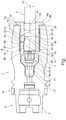
- the chuck 1 shown in the figure has a coupling section 3, which serves to connect the chuck 1 in a known manner to a machine tool, either directly or via an adapter, an intermediate piece or the like, in order to introduce a torque into the chuck 1 to be able to rotate a tool inserted into the chuck 1.
- the tool can be a drill, milling cutter, grinding tool or the like.
- the coupling section 3 has a known hollow shaft 7, via which the chuck 1 can be held securely in the machine tool or an adapter, intermediate piece or the like.
- the chuck 1 also has a receiving section 9 which is provided with a recess 11 which opens toward the free end 13 of the receiving section 9.
- the exemplary embodiment shown here is preferably provided with a central part 15, which comprises, for example, a gripper groove 17 into which a gripping tool for handling the chuck 1 can engage, for example in order to automatically remove it from a machine tool or insert it into it.
- a sleeve 19 is inserted into the recess 11 of the chuck 1, the outer diameter of which is adapted to the inner diameter of the recess 11 such that the sleeve 19 can be securely fixed in the recess 11 of the receiving section 9.
- the receiving section 9 has a hydraulic expansion chuck 21, with the aid of which the sleeve 19 and thus the tool 5 inserted into it can be held securely.
- Hydraulic chucks of the type mentioned here are known. They have a thin-walled wall section 22, which is at least in some areas part of the inner wall 23 of the recess 11.
- a cavity 27 is provided which is filled with a hydraulic fluid which can be acted upon by an overpressure in a suitable and known manner.
- an overpressure is built up in the cavity 27 and thus the elastic wall section 22 pushes into the interior of the recess 11 and thus against the outer wall of the sleeve 19. In this way, the sleeve 19 is held firmly in the receiving section 9.
- the sleeve 19 has a base body 29 which has a wall 33 which laterally surrounds a cavity 31, the outside diameter of which is smaller than the inside diameter of the recess 11 and the inside diameter of which is slightly larger in the region of the cavity 31 than that of the tool 5, which is preferably provided with a shaft 35 is provided, which is arranged inside the sleeve 19 or in the cavity 31.
- a recess 39 is made in the peripheral surface 37 of the shaft 35, which has at least on the end 41 of the shaft 37 lying in the interior of the sleeve 19 an oblique boundary surface which starts from a bottom 43 of the recess 39.
- an oblique boundary surface 45 can also be provided, the two boundary surfaces 41 and 45 enclosing an angle that opens outwards as seen from a longitudinal axis 47 of the chuck 1.
- the chuck 1 has a securing device 49 which serves to fix a tool inserted into the cavity 31 of the sleeve 19 in such a way that it cannot be displaced in the axial direction, that is to say in the direction of the central axis 47.
- the securing device 49 of the exemplary embodiment of a chuck 1 shown here has a bolt 51 which can be displaced at an acute angle, preferably perpendicular to the longitudinal extension of the sleeve 19, the length of which in the radial direction to the central axis 47 is greater than the thickness of the wall which is also measured in this direction 33 of the sleeve 19.
- the chuck 1 is shown so that the sleeve 19 in the recess 11 is firmly clamped, here by the hydraulic expansion chuck 21.
- the elastic wall section 22 of the hydraulic expansion chuck 21 therefore lies firmly on the outside on the peripheral surface 53 of the sleeve 19 and also on the outside 55 of the bolt 51.
- the recess 39 in the shaft 35 of the tool 1, viewed in the direction of the central axis 47, is arranged such that the inner surface 59 of the bolt 51 in this functional position of the chuck 1, that is to say in particular when the hydraulic expansion chuck 21 is activated, preferably at a distance within the recess 39 to the bottom 43 is arranged.
- the bolt 51 has a chamfer 61 facing the oblique boundary surface 41 of the recess 39, which forms a wedge gear together with the oblique boundary surface 41. If the bolt 51 is thus pushed into the recess 39, the tool 1 is subjected to a force which acts in the direction of the central axis 47 in the figure shown here and pulls the tool 5 into the cavity 31 of the sleeve 19.
- the sleeve 19 comprises a prestressing element 63, which acts on the tool 5 inserted into the cavity 31 with a force directed to the right, that is to say acting in the direction of the free end 13 of the receiving section 9. This force causes the tool 5 to bear precisely against the bolt 51 and is thus fixed in the chuck 1 in a precisely predetermined axial starting position.
- the sleeve 19 is provided with a collar 65 which rests on the end face 66 of the chuck 1 provided at the end 13 when the sleeve 19 is in the Recess 11 is inserted. Due to the exactly predetermined starting position of the sleeve 19 in the receiving section 9 and by ensuring the axial position of the tool 5 inside the sleeve 19 by means of the biasing element 63 and the securing device 49, the axial starting position of the tool 5 in the chuck 1 can be exactly can be set.
- the schematic diagram of the chuck 1 shown in the figure shows that the securing device 49 comprises the bolt 51.
- this is held by a holding arm 67 in a recess 69 in the wall 33 of the sleeve 19 at the desired position shown here.
- the holding arm 67 is preferably designed as a spring bar, so that the bolt 51 is held at a desired position in the recess 69.
- the bolt 51 is positioned such that its outside 55 is flush with the peripheral surface 53 of the sleeve 19.
- the outside 55 of the bolt 51 can be ground cylindrically, that is, after the insertion of the sleeve 19, it lies against the inside surface 59 of the cavity 31 over the entire surface.
- the bolt 51 can spring outwards due to the inherent elasticity of the holding arm 67. If the tool 5 is pushed deeply enough into the cavity 31 of the sleeve 19, the bolt 51 is displaced, preferably in a resilient manner, into the recess 39 made in the peripheral surface 37 of the shaft 35 of the tool 5. This allows a user to see that the tool 5 is inserted deep enough into the cavity 31 and rotated so that the bolt 51 can enter the recess 39. If the tool 5 and the sleeve 19 are inserted into the receiving section 9 in the relative position given at this moment, this is possible without any problems because the outside 55 of the bolt 51 does not strike the end face 66.
- the preferably resilient design of the holding arm 67 is therefore advantageous for the insertion of a tool 5 into the sleeve 19, because the desired positioning of the tool 5 within the cavity 31 can be recognized by the deflection of the bolt 51.
- the holding arm 67 is a separate element and to attach it on the one hand to the bolt 51 and on the other hand to the wall 33 of the sleeve 19 in a suitable manner, be it by soldering, welding, laser welding or the like.
- the holding arm 67 which is preferably designed as a spring bar, is very particularly preferably designed as an integral part of the wall 33 and / or the bolt 51.
- the bolt 51 is an integral part of the wall 33, which is indicated here by way of example in the figure by the common hatching of the sleeve 19, the holding arm 67 and the bolt 51.
- the bolt 51 measured in the direction of the central axis 47, is longer than the thickness of the wall 33, it may be advantageous to manufacture the wall 33 and the holding arm 67 acting as a spring bar in one piece, for example by laser machining a sleeve 19 or wire erosion, and then to attach the bolt 51 to the free end of the holding arm 67.
- the bolt 51 springs into the depression 39, so that the sleeve 19 can now easily be inserted into the Cavity 31 can be inserted until it assumes its desired axial position by abutment of the collar 65 on the end face 66 of the receiving section 9.
- the recess 39 has a greater extent than the width of the bolt 51
- Tool 5 is pushed by the biasing element 63 after inserting the sleeve 19 with the oblique boundary surface 41 against the chamfer 61 of the bolt 51 and thus assumes a desired axial position within the sleeve 19.
- the sleeve 19 can now be fixed in the receiving section 9 or in the recess 11 thereof by activating the hydraulic expansion chuck 21. As a result, the tool 5 is then on the chuck 1 fixed.
- the securing device 49 which in the exemplary embodiment shown here has a bolt 51 held by a holding arm 67, which is preferably designed as a spring arm, the following results:
- the holding arm 67 connected to the bolt 51 can be dispensed with. It is crucial for the functioning of the securing device 49 that the bolt 51 in the wall 33 of the sleeve 19 can be displaced at an acute angle, preferably perpendicular to the longitudinal extension of the sleeve 19, and has a length that is greater than the thickness of the wall 33
- the displaceability can also be ensured if the bolt 51 is displaceably housed in a suitable recess, not shown in the figure, for example a bore.
- the bolt 51 it is then possible for the bolt 51 to be displaced outwards when a tool 5 is introduced into the recess 11 of the receiving section 9, that is to say to move away from the central axis 47. If the tool 5 is correctly aligned, as was explained above, the bolt 51 can be moved into the recess 39 made in the tool 5 or its shaft 35 after the tool 5 has been completely inserted into the recess 11. In this position, as in the exemplary embodiment explained above, it is then held in place, for example by the elastic wall section 22, when the hydraulic expansion chuck 21 is activated.
- the bolt 51 can be held in the associated recess or bore in a simple, known manner, for example by an O-ring which is pushed onto the outer surface of the bolt 51.
- the O-ring can also be accommodated in a groove made in the outer surface, or else in a groove which is made in the inner surface of the recess or bore receiving the bolt 51.
- the sleeve 19 can preferably have one or more longitudinal slots, not shown here, in the wall 33. As a result, it can be compressed during clamping, for example when the hydraulic expansion chuck 21 is activated, so that the tool 5 is thereby also fixedly fixed in the receiving section 9.
- the sleeve 19 described here can be used as an adapter sleeve. In this case, it is necessary, for example, to provide sleeves with different inner diameters of the cavity 31 in order to be able to introduce different tool sizes. It is also conceivable to provide different sleeves 19 with bolts 51 arranged at different positions, in order to enable adaptation to different tools 5 with differently positioned recesses 39.
- the chuck 1 can be equipped with a predetermined configuration of the receiving section 9 or the associated recess 11 with different sleeves 19 in order to be able to hold different tools and to be able to fix them in the desired axial position.
Description
Die Erfindung betrifft ein Spannfutter gemäß Oberbegriff des Anspruchs 1. Ein solches Spannfutter ist aus dem Dokument
Spannfutter der hier angesprochenen Art sind bekannt. Sie weisen einen Kupplungsabschnitt sowie einen Aufnahmeabschnitt auf, über den das Spannfutter mit einer Werkzeugmaschine unmittelbar oder über ein Zwischenstück beziehungsweise einen Adapter oder dergleichen mit einem Drehmoment beaufschlagbar ist, um ein von diesem aufgenommenes Werkzeug in Rotation zu versetzen. Der Aufnahmeabschnitt ist mit einer Ausnehmung versehen, in die eine Hülse einsetzbar ist, welche das Werkzeug aufnimmt. Sie ist mit einer Sicherungseinrichtung versehen, mit deren Hilfe das Werkzeug innerhalb der Hülse axial festgelegt wird. Die axiale Sicherung eines Werkzeugs innerhalb der Hülse ist in vielen Anwendungsbereichen von entscheidender Bedeutung, weil beispielsweise während eines Fräsvorgangs mit hoher Vorschubgeschwindigkeit das Werkzeug aus der Hülse, und damit aus dem Aufnahmeabschnitt eines Spannfutters, herausgezogen werden kann. Bekannte Sicherungseinrichtungen weisen beispielsweise mindestens einen Stift auf, welcher die Wandung der Hülse vorzugsweise in einer Ebene durchdringt, auf welcher die Längsachse der Hülse senkrecht steht. Der die Hülse durchdringende Stift tritt in Eingriff mit dem in die Hülse eingesetzten Werkzeug, beispielsweise in eine Quernut, das heißt in eine senkrecht zur Längserstreckung des Werkzeugs verlaufende Nut. Nach dem Einsetzen des Stifts in die Hülse kann das Werkzeug nicht mehr aus dieser in axialer Richtung herausgezogen werden. Bekannt ist es außerdem, in die Wandung der Hülse eine Sicherungsschraube einzudrehen, welche mit einer in der Umfangsfläche des Werkzeugs beziehungsweise dessen Schafts eingebrachte Vertiefung in Eingriff tritt. Derartige Sicherungseinrichtungen weisen folgenden Nachteil auf: Nach dem Einsetzen eines Werkzeugs in die Hülse bedarf es eines zusätzlichen Arbeitsganges, nämlich des Einsetzens eines Stifts zur axialen Fixierung des Werkzeugs innerhalb der Hülse oder Betätigung einer in die Wand der Hülse eingesetzten Schraube, die daraufhin in eine seitliche Vertiefung des Werkzeugs eingreift.Chucks of the type mentioned here are known. They have a coupling section and a receiving section, via which the chuck can be acted upon with a machine tool directly or via an intermediate piece or an adapter or the like, in order to set a tool received by it in rotation. The receiving section is provided with a recess into which a sleeve can be inserted, which receives the tool. It is provided with a securing device, with the aid of which the tool is axially fixed within the sleeve. The axial securing of a tool within the sleeve is of crucial importance in many areas of application because, for example, the tool can be pulled out of the sleeve, and thus out of the receiving section of a chuck, during a milling process with a high feed rate. Known securing devices have, for example, at least one pin, which preferably penetrates the wall of the sleeve in a plane on which the longitudinal axis of the sleeve is perpendicular. The pin penetrating the sleeve engages with the tool inserted into the sleeve, for example into a transverse groove, that is to say into a groove running perpendicular to the longitudinal extension of the tool. After inserting the pin into the sleeve, the tool can no longer be pulled out of it in the axial direction. It is also known in the wall of the sleeve a locking screw to screw in, which comes into engagement with a recess made in the peripheral surface of the tool or its shank. Such safety devices have the following disadvantage: After inserting a tool in the sleeve, an additional operation is required, namely the insertion of a pin for axially fixing the tool within the sleeve or actuation of a screw inserted into the wall of the sleeve, which is then inserted into a side Tool recess engages.
Aufgabe der Erfindung ist es daher, ein Spannfutter zu schaffen, welches diesen Nachteil vermeidet.The object of the invention is therefore to provide a chuck which avoids this disadvantage.
Zur Lösung dieser Aufgabe wird ein Spannfutter der oben genannten Art vorgeschlagen, welches die in Anspruch 1 genannten Merkmale aufweist. Dieses Spannfutter weist einen Kupplungsabschnitt auf, über welchen es mit einer Werkzeugmaschine entweder unmittelbar oder über einen Adapter, ein Zwischenstück oder dergleichen verbindbar ist, außerdem einen Aufnahmeabschnitt. Dieser weist eine Ausnehmung auf, in die eine mit einer Wand versehene Hülse einbringbar ist, in welche ein Werkzeug einsetzbar ist. Die Hülse weist eine Sicherungseinrichtung zur axialen Festlegung des Werkzeugs innerhalb der Hülse auf. Das Spannfutter zeichnet sich dadurch aus, dass die Sicherungseinrichtung einen Bolzen aufweist, der in einer Aussparung in der Wand der Hülse gelagert und unter einem spitzen Winkel, vorzugsweise im Wesentlichen in vertikaler Richtung zur Längserstreckung der Hülse beweglich ist. Die senkrecht zur Längserstreckung der Hülse gemessene Länge des Bolzens ist größer als die Dicke der Wand der Hülse. Der Bolzen kann beim Einsetzen eines Werkzeugs in das Innere der Hülse nach außen verlagert werden, also aus dem für das Werkzeug vorgesehenen Hohlraum der Hülse heraus, sodass das Werkzeug leicht einsetzbar ist. Beim Festspannen der Hülse mit dem Werkzeug innerhalb des Aufnahmeabschnitts wird der Bolzen in das Innere der Hülse und in eine in der Seitenwand des Werkzeugs vorgesehene Vertiefung hineingedrückt, sodass das Werkzeug axial in der Hülse und damit im Spannfutter gesichert ist.To solve this problem, a chuck of the type mentioned above is proposed, which has the features mentioned in claim 1. This chuck has a coupling section, via which it can be connected to a machine tool either directly or via an adapter, an intermediate piece or the like, and also a receiving section. This has a recess into which a sleeve provided with a wall can be inserted, into which a tool can be inserted. The sleeve has a securing device for axially fixing the tool within the sleeve. The chuck is characterized in that the securing device has a bolt which is mounted in a recess in the wall of the sleeve and is movable at an acute angle, preferably essentially in the vertical direction, to the longitudinal extent of the sleeve. The length of the bolt measured perpendicular to the longitudinal extent of the sleeve is greater than the thickness of the wall of the sleeve. When inserting a tool, the bolt can be displaced outwards into the interior of the sleeve, that is to say from the cavity provided for the tool the sleeve so that the tool is easy to use. When the sleeve is clamped with the tool within the receiving section, the bolt is pressed into the interior of the sleeve and into a recess provided in the side wall of the tool, so that the tool is secured axially in the sleeve and thus in the chuck.
Ein bevorzugtes Ausführungsbeispiel des Spannfutters zeichnet sich dadurch aus, dass der Bolzen von einem vorzugsweise als Federsteg ausgebildeten Haltearm gehalten wird, der den Bolzen mit der Hülse verbindet. Diese Ausgestaltung des Spannfutters zeichnet sich durch einen sehr einfachen Aufbau aus und ist sehr funktionssicher.A preferred embodiment of the chuck is characterized in that the bolt is held by a holding arm, which is preferably designed as a spring bar and connects the bolt to the sleeve. This configuration of the chuck is characterized by a very simple structure and is very reliable.
Besonders bevorzugt wird ein Ausführungsbeispiel, welches sich dadurch auszeichnet, dass der Federsteg vom Rand der den Bolzen aufnehmenden Aussparung ausgeht und mit dem Bolzen verbunden ist. Diese Art einer federnden Lagerung des Bolzens zeichnet sich durch einen äußerst geringen Raumbedarf aus, sodass weder am Aufnahmeabschnitt noch an dem aufzunehmenden Werkzeug irgendwelche Änderungen vorgenommen werden müssen, um eine Anpassung an die federnde Lagerung zu realisieren.An embodiment is particularly preferred which is characterized in that the spring bar extends from the edge of the recess receiving the bolt and is connected to the bolt. This type of resilient mounting of the bolt is characterized by an extremely small space requirement, so that no changes need to be made either to the receiving section or to the tool to be accommodated in order to adapt to the resilient mounting.
Ein besonders bevorzugtes Ausführungsbeispiel zeichnet sich dadurch aus, dass der Federsteg integraler Bestandteil der Wand und/oder des Bolzens ist, sodass auf Befestigungsmittel zur Anbringung des Federstegs an der Wand und/oder dem Bolzen verzichtet werden kann.A particularly preferred embodiment is characterized in that the spring bar is an integral part of the wall and / or the bolt, so that fastening means for attaching the spring bar to the wall and / or the bolt can be dispensed with.
Ein weiteres bevorzugtes Ausführungsbeispiel des Spannfutters zeichnet sich dadurch aus, dass die Hülse ein Vorspannelement aufweist, welches ein in die Hülse eingesetztes Werkzeug mit einer axialen Kraft beziehungsweise Vorspannkraft beaufschlagt, sodass dieses während des Einspannens der Hülse im Aufnahmeabschnitt des Spannfutters in einer exakt vorgegebenen Axialposition angeordnet ist.Another preferred exemplary embodiment of the chuck is characterized in that the sleeve has a prestressing element which has a tool inserted into the sleeve with a Axial force or biasing force is applied so that it is arranged in a precisely predetermined axial position in the receiving section of the chuck during the clamping of the sleeve.
Die Erfindung wird im Folgenden anhand der Zeichnung näher erläutert. Diese umfasst eine einzige Figur, welche eine Prinzipskizze eines Längsschnitts des Spannfutters wiedergibt.The invention is explained in more detail below with reference to the drawing. This comprises a single figure, which shows a basic sketch of a longitudinal section of the chuck.
Das in der Figur wiedergegebene Spannfutter 1 weist einen Kupplungsabschnitt 3 auf, der dazu dient, das Spannfutter 1 auf bekannte Weise mit einer Werkzeugmaschine, entweder unmittelbar oder über einen Adapter, ein Zwischenstück oder dergleichen drehfest zu verbinden, um ein Drehmoment in das Spannfutter 1 einleiten zu können und damit ein in das Spannfutter 1 eingesetztes Werkzeug in Rotation zu versetzen. Bei dem Werkzeug kann es sich um einen Bohrer, Fräser, ein Schleifwerkzeug oder dergleichen handeln. Der Kupplungsabschnitt 3 weist bei dem hier dargestellten Ausführungsbeispiel einen bekannten Hohlschaft 7 auf, über den das Spannfutter 1 sicher in der Werkzeugmaschine beziehungsweise einem Adapter, Zwischenstück oder dergleichen gehalten werden kann.The chuck 1 shown in the figure has a
Das Spannfutter 1 weist außerdem einen Aufnahmeabschnitt 9 auf, der mit einer Ausnehmung 11 versehen ist, welche sich zum freien Ende 13 des Aufnahmeabschnitts 9 öffnet. Das hier dargestellte Ausführungsbeispiel ist vorzugsweise mit einem Mittelteil 15 versehen, welches beispielsweise eine Greiferrille 17 umfasst, in die ein Greifwerkzeug zur Handhabung des Spannfutters 1 eingreifen kann, beispielsweise um es automatisch aus einer Werkzeugmaschine zu entnehmen oder in diese einzusetzen.The chuck 1 also has a receiving
In die Ausnehmung 11 des Spannfutters 1 ist eine Hülse 19 eingesetzt, deren Außendurchmesser an den Innendurchmesser der Ausnehmung 11 so angepasst ist, dass die Hülse 19 sicher in der Ausnehmung 11 des Aufnahmeabschnitts 9 fixiert werden kann. Beispielhaft ist hier vorgesehen, dass der Aufnahmeabschnitt 9 ein Hydrodehnspannfutter 21 aufweist, mit dessen Hilfe die Hülse 19 und damit das in diese eingesetzte Werkzeug 5 sicher gehalten werden kann. Hydrodehnspannfutter der hier angesprochenen Art sind bekannt. Sie weisen einen dünnwandigen Wandabschnitt 22 auf, welcher zumindest bereichsweise Teil der Innenwand 23 der Ausnehmung 11 ist. In einem der Ausnehmung 11 abgewandten Bereich in der Wandung 25 des Aufnahmeabschnitts 9 ist in diesem Fall ein Hohlraum 27 vorgesehen, der mit einer Hydraulikflüssigkeit gefüllt ist, die auf geeignete und bekannte Weise mit einem Überdruck beaufschlagbar ist. Zur Fixierung der Hülse 19 in der Ausnehmung 11 des Aufnahmeabschnitts 9 wird ein Überdruck in dem Hohlraum 27 aufgebaut und damit der elastische Wandabschnitt 22 in das Innere der Ausnehmung 11 und damit gegen die Außenwand der Hülse 19 drängt. Auf diese Weise wird die Hülse 19 fest im Aufnahmeabschnitt 9 gehalten.A
Denkbar ist es im Übrigen, statt eines Hydrodehnspannfutters 21 ein Schrumpffutter vorzusehen. Bei einem derartig bekannten Futter ist vorgesehen, dass der Innendurchmesser der Ausnehmung 11 etwas kleiner ist als der Außendurchmesser der im Aufnahmeabschnitt 9 zu fixierenden Hülse 19. Durch Erwärmen der Wandung 29 weitet sich die Ausnehmung 11 auf und kann damit die Hülse 19 aufnehmen. Diese kann gegebenenfalls auch noch zusätzlich gekühlt werden. Die Funktionsweise eines Spannfutters ist bekannt, sodass hier nicht näher darauf eingegangen wird.It is also conceivable to provide a shrink fit chuck instead of a
Die Hülse 19 weist einen Grundkörper 29 auf, der eine einen Hohlraum 31 seitlich umschließende Wand 33 aufweist, deren Außendurchmesser kleiner ist als der Innendurchmesser der Ausnehmung 11 und deren Innendurchmesser im Bereich des Hohlraums 31 etwas größer ist als der des Werkzeugs 5, welches vorzugsweise mit einem Schaft 35 versehen ist, der im Inneren der Hülse 19 beziehungsweise in dem Hohlraum 31 angeordnet ist.The
In die Umfangsfläche 37 des Schafts 35 ist eine Vertiefung 39 eingebracht, welche zumindest auf dem im Inneren der Hülse 19 liegenden Ende 41 des Schafts 37 eine schräge Begrenzungsfläche aufweist, die von einem Boden 43 der Vertiefung 39 ausgeht. An der gegenüberliegenden Seite des Bodens 43 kann ebenfalls eine schräge Begrenzungsfläche 45 vorgesehen werden, wobei die beiden Begrenzungsflächen 41 und 45 einen Winkel einschließen, der sich von einer Längsachse 47 des Spannfutters 1 aus gesehen nach außen öffnet.A
Das Spannfutter 1 weist eine Sicherungseinrichtung 49 auf, die dazu dient, ein in den Hohlraum 31 der Hülse 19 eingesetztes Werkzeug so festzulegen, dass es - in axialer Richtung, also in Richtung der Mittelachse 47 gesehen - nicht verlagerbar ist.The chuck 1 has a securing device 49 which serves to fix a tool inserted into the
Die Sicherungseinrichtung 49 des hier dargestellten Ausführungsbeispiels eines Spannfutters 1 weist einen unter einem spitzen Winkel, vorzugsweise senkrecht zur Längserstreckung der Hülse 19 verlagerbaren Bolzen 51 auf, dessen in radialer Richtung zur Mittelachse 47 gemessene Länge größer ist als die ebenfalls in dieser Richtung gemessene Dicke der Wand 33 der Hülse 19. In der Figur ist das Spannfutter 1 so dargestellt, dass die Hülse 19 in der Ausnehmung 11 fest eingespannt ist, hier also durch das Hydrodehnspannfutter 21. Der elastische Wandabschnitt 22 des Hydrodehnspannfutters 21 liegt daher von außen auf der Umfangsfläche 53 der Hülse 19 und auch auf der Außenseite 55 des Bolzens 51 fest an. Da der Bolzen 51 dicker ist als die Wand 33, ragt dessen Innenseite 57 über die Innenfläche 59 der Hülse 19 in den Hohlraum 31 hinein. Die Vertiefung 39 im Schaft 35 des Werkzeugs 1 ist, in Richtung der Mittelachse 47 gesehen, so angeordnet, dass die Innenfläche 59 des Bolzens 51 in dieser Funktionsstellung des Spannfutters 1, also insbesondere bei aktiviertem Hydrodehnspannfutter 21, innerhalb der Vertiefung 39 vorzugsweise in einem Abstand zu deren Boden 43 angeordnet ist.The securing device 49 of the exemplary embodiment of a chuck 1 shown here has a
Der Bolzen 51 weist eine der schrägen Begrenzungsfläche 41 der Vertiefung 39 zugewandte Fase 61 auf, die gemeinsam mit der schrägen Begrenzungsfläche 41 ein Keilgetriebe bildet. Wird also der Bolzen 51 in die Vertiefung 39 gedrängt, so wird das Werkzeug 1 mit einer Kraft beaufschlagt, die in Richtung der Mittelachse 47 in der hier dargestellten Figur nach links wirkt und das Werkzeug 5 in den Hohlraum 31 der Hülse 19 hineinzieht.The
Die Figur zeigt noch, dass die Hülse 19 ein Vorspannelement 63 umfasst, welches das in den Hohlraum 31 eingesetzte Werkzeug 5 mit einer nach rechts gerichteten Kraft, die also in Richtung auf das freie Ende 13 des Aufnahmeabschnitts 9 wirkt, beaufschlagt. Diese Kraft bewirkt, dass das Werkzeug 5 exakt an dem Bolzen 51 anliegt und damit in einer präzise vorgegebenen axialen Ausgangslage im Spannfutter 1 fixiert wird.The figure also shows that the
Um beim Einsetzen der Hülse 19 in die Ausnehmung 11 des Aufnahmeabschnitts 9 eine exakte axiale Ausgangsposition zu gewährleisten, ist die Hülse 19 mit einem Kragen 65 versehen, welcher auf der am Ende 13 vorgesehenen Stirnfläche 66 des Spannfutters 1 aufliegt, wenn die Hülse 19 in die Ausnehmung 11 eingeschoben wird. Durch die damit exakt vorgegebene Ausgangsposition der Hülse 19 im Aufnahmeabschnitt 9 und durch die Gewährleistung der axialen Position des Werkzeugs 5 im Inneren der Hülse 19 mittels des Vorspannelements 63 und der Sicherungseinrichtung 49 kann nach dem Einsetzen eines Werkzeugs 5 in das Spannfutter 1 dessen axiale Ausgangsposition exakt eingestellt werden.In order to ensure an exact axial starting position when inserting the
Der in der Figur wiedergegebenen Prinzipskizze des Spannfutters 1 ist zu entnehmen, dass die Sicherungseinrichtung 49 den Bolzen 51 umfasst. Dieser wird bei dem hier dargestellten Ausführungsbeispiel von einem Haltearm 67 in einer Aussparung 69 in der Wand 33 der Hülse 19 an der hier dargestellten, gewünschten Position gehalten. Vorzugsweise ist der Haltearm 67 als Federsteg ausgebildet, sodass der Bolzen 51 an einer gewünschten Position in der Aussparung 69 gehalten wird. Erfindungsgemäß ist der Bolzen 51 so positioniert, dass dessen Außenseite 55 mit der Umfangsfläche 53 der Hülse 19 fluchtet. Dabei kann die Außenseite 55 des Bolzens 51 zylindrisch geschliffen sein, das heißt, sie liegt nach dem Einsetzen der Hülse 19 vollflächig an der Innenfläche 59 des Hohlraums 31 an. Wird in die Hülse 19 ein Werkzeug 5 eingeschoben, so kann der Bolzen 51 aufgrund der Eigenelastizität des Haltearms 67 nach außen federn. Wird das Werkzeug 5 tief genug in den Hohlraum 31 der Hülse 19 eingeschoben, wird der Bolzen 51, vorzugsweise federnd, in die in die Umfangsfläche 37 des Schafts 35 des Werkzeugs 5 eingebrachte Vertiefung 39 verlagert. Dadurch kann ein Benutzer erkennen, dass das Werkzeug 5 tief genug in den Hohlraum 31 eingeschoben und so gedreht ist, dass der Bolzen 51 in die Vertiefung 39 eintreten kann. Werden das Werkzeug 5 und die Hülse 19 in der in diesem Moment gegebenen Relativposition in den Aufnahmeabschnitt 9 eingeschoben, so ist dies problemlos möglich, weil die Außenseite 55 des Bolzens 51 nicht an der Stirnfläche 66 anschlägt.The schematic diagram of the chuck 1 shown in the figure shows that the securing device 49 comprises the
Die vorzugsweise federnde Ausgestaltung des Haltearms 67 ist also für das Einbringen eines Werkzeugs 5 in die Hülse 19 vorteilhaft, weil durch das Einfedern des Bolzens 51 die gewünschte Positionierung des Werkzeugs 5 innerhalb des Hohlraums 31 erkennbar wird.The preferably resilient design of the holding
Grundsätzlich ist es möglich, den Haltearm 67 als getrenntes Element auszubilden und einerseits an dem Bolzen 51 und andererseits an der Wand 33 der Hülse 19 auf geeignete Weise anzubringen, sei es durch Löten, Schweißen, Laserschweißen oder dergleichen. Ganz besonders bevorzugt wird der vorzugsweise als Federsteg ausgebildete Haltearm 67 als integraler Bestandteil der Wand 33 und/oder des Bolzens 51 ausgebildet. Insbesondere wird bevorzugt, wenn der Bolzen 51 integraler Bestandteil der Wand 33 ist, was hier beispielhaft in der Figur durch die gemeinsame Schraffur der Hülse 19, des Haltearms 67 und des Bolzens 51 angedeutet ist.In principle, it is possible to form the holding
Da der Bolzen 51 in Richtung der Mittelachse 47 gemessen länger ist als die Dicke der Wand 33, mag es vorteilhaft sein, die Wand 33 und den als Federsteg wirkenden Haltearm 67 aus einem Stück herzustellen, beispielsweise durch Laserbearbeitung einer Hülse 19 oder Drahterosion, und dann am freien Ende des Haltearms 67 den Bolzen 51 anzubringen.Since the
Entscheidend ist, dass es keiner zusätzlichen Handhabungsschritte bedarf, um eine axiale Sicherung des Werkzeugs 5 in der Hülse 19 zu gewährleisten. Es ist also nicht erforderlich, durch die Wand 33 der Hülse quer zur Längserstreckung des Werkzeugs 5 einen Stift zu führen, der in eine Vertiefung 39 eingreift, wie sie in der Figur dargestellt ist. Auch ist es nicht erforderlich, nach Einbringen des Werkzeugs 5 in die Hülse 19 eine in der Wand 33 der Hülse 19 vorhandene Spannschraube anzuziehen. Es ist vielmehr auf einfache Wiese möglich, das Werkzeug 5 in die Hülse 19 einzustecken. Wenn der Haltearm 67 als Federsteg ausgebildet ist, wird beim Einführen des Werkzeugs 5 in den Hohlraum 31 der Bolzen 51 - vorzugsweise federnd - nach außen gedrängt. Sobald er im Bereich der Vertiefung 39 angeordnet ist, weil das Werkzeug 5 tief genug in den Hohlraum 31 eingeführt ist und sich in der gewünschten Relativdrehstellung zur Hülse befindet, federt der Bolzen 51 in die Vertiefung 39 ein, sodass die Hülse 19 nunmehr problemlos in den Hohlraum 31 eingeführt werden kann, bis sie ihre gewünschte Axialposition durch Anschlag des Kragens 65 an der Stirnfläche 66 des Aufnahmeabschnitts 9 einnimmt. Es schadet nicht, wenn das Werkzeug 5, in axialer Richtung gesehen, dabei etwas tiefer in den Hohlraum 31 eingeschoben wird, weil vorzugsweise, in Richtung der Mittelachse 67 gemessen, die Vertiefung 39 eine größere Erstreckung hat, als die Breite des Bolzens 51. Das Werkzeug 5 wird durch das Vorspannelement 63 nach Einsetzen der Hülse 19 mit der schrägen Begrenzungsfläche 41 gegen die Fase 61 des Bolzens 51 gedrängt und nimmt damit eine gewünschte Axialposition innerhalb der Hülse 19 ein. Nun kann die Hülse 19 im Aufnahmeabschnitt 9 beziehungsweise in dessen Ausnehmung 11 durch Aktivierung des Hydrodehnspannfutters 21 fixiert werden. Dadurch ist dann auch das Werkzeug 5 am Spannfutter 1 fixiert. Denkbar ist es auch, an dem dem Kragen 65 abgewandten Ende der Hülse ein Außengewinde 71 vorzusehen, welches in ein Innengewinde 73 in einer Ausnehmung 75 eingreift, die koaxial zur Mittelachse 47 in das Spannfutter 1 eingebracht ist.It is crucial that no additional handling steps are required to ensure that the
Aus den Erläuterungen zur Funktionsweise der Sicherungseinrichtung 49, die bei dem hier dargestellten Ausführungsbeispiel einen von einem - vorzugsweise als Federarm ausgebildeten - Haltearm 67 gehaltenen Bolzen 51 aufweist, ergibt sich Folgendes:
Auf den mit dem Bolzen 51 verbundenen Haltearm 67 kann verzichtet werden. Entscheidend für die Funktionsweise der Sicherungseinrichtung 49 ist hier, dass der Bolzen 51 in der Wand 33 der Hülse 19 unter einem spitzen Winkel, vorzugsweise senkrecht zur Längserstreckung der Hülse 19 verlagerbar ist und eine Länge aufweist, die größer ist, als die Dicke der Wand 33. Die Verlagerbarkeit kann auch gewährleistet werden, wenn der Bolzen 51 in einer geeigneten, in der Figur nicht dargestellten Ausnehmung, beispielsweise einer Bohrung verschieblich untergebracht ist. Es ist dann möglich, dass der Bolzen 51 beim Einbringen eines Werkzeugs 5 in die Ausnehmung 11 des Aufnahmeabschnitts 9 nach außen verlagert wird, also sich von der Mittelachse 47 entfernt. Bei korrekter Ausrichtung des Werkzeugs 5, wie sie oben erläutert wurde, kann der Bolzen 51 nach dem vollständigen Einführen des Werkzeugs 5 in die Ausnehmung 11 in die in dem Werkzeug 5 beziehungsweise dessen Schaft 35 eingebrachte Vertiefung 39 hineinverlagert werden. In dieser Position wird er dann, wie bei dem oben erläuterten Ausführungsbeispiel festgehalten, beispielsweise durch den elastischen Wandabschnitt 22, bei Aktivierung des Hydrodehnspannfutters 21.From the explanations of the functioning of the securing device 49, which in the exemplary embodiment shown here has a
The holding
Der Bolzen 51 kann auf einfache, bekannte Weise in der zugehörigen Ausnehmung beziehungsweise Bohrung gehalten werden, beispielsweise durch einen O-Ring, der auf die Außenfläche des Bolzens 51 aufgeschoben ist. Der O-Ring kann auch in einer in die Außenfläche eingebrachten Nut untergebracht sein, oder aber in einer Nut, die in die Innenfläche der den Bolzen 51 aufnehmenden Ausnehmung beziehungsweise Bohrung eingebracht ist.The
Die Hülse 19 kann vorzugsweise einen oder mehrere hier nicht dargestellte Längsschlitze in der Wand 33 aufweisen. Dadurch kann sie beim Einspannen, beispielsweise bei Aktivierung des Hydrodehnspannfutters 21, zusammengedrückt werden, sodass dadurch auch das Werkzeug 5 fest im Aufnahmeabschnitt 9 fixiert wird.The
Die hier beschriebene Hülse 19 kann als Adapterhülse verwendet werden. In diesem Fall ist es erforderlich, beispielsweise Hülsen mit verschiedenem Innendurchmesser des Hohlraums 31 bereitzustellen, um verschiedene Werkzeuggrößen einbringen zu können. Auch ist es denkbar, verschiedene Hülsen 19 mit an unterschiedlichen Positionen angeordneten Bolzen 51 bereitzustellen, um auch so eine Anpassung an verschiedene Werkzeuge 5 mit verschieden positionierten Vertiefungen 39 zu ermöglichen.The
Auf diese Weise kann das Spannfutter 1 mit einer vorgegebenen Ausgestaltung des Aufnahmeabschnitts 9 beziehungsweise der zugehörigen Ausnehmung 11 mit verschiedenen Hülsen 19 bestückt werden, um unterschiedliche Werkzeuge aufnehmen und in gewünschter axialer Position fixieren zu können.In this way, the chuck 1 can be equipped with a predetermined configuration of the receiving
Claims (6)
- A clamping chuck (1) comprising- a coupling section (3),- a receiving section (9) having a recess (11),- a sleeve (19), which can be inserted into the recess (11) of the receiving section (9) and has a wall (33), which serves to receive a tool (5), and comprising- a securing device (49) for axially securing a tool (5) inside the sleeve (19), wherein- the securing device (49) has a bolt (51), which is supported in a recess (69) in the wall (33) of the sleeve (19) and can be moved at an acute angle, preferably essentially in the vertical direction to the longitudinal extension of the sleeve (19), and that- the length of the bolt (51), measured perpendicular to the longitudinal extension of the sleeve (19), is greater than the thickness of the wall (33), characterised in that- an outer side (55) of the bolt (51) is aligned with an outer circumferential surface (53) of the sleeve (19), and that- the outer side (55) of the bolt (51) is ground cylindrically.
- The clamping chuck according to claim 1, characterised in that the bolt (51) is held by a holding arm (67), which is preferably formed as spring bar and which is connected to the bolt (51) on the one hand and to the sleeve (19) on the other hand.
- The clamping chuck according to claim 2, characterised in that the spring bar starts at the edge of the recess (69), which receives the bolt (51).
- The clamping chuck according to claim 3, characterised in that the spring bar is integral part of the wall (33) and/or of the bolt (51).
- The clamping chuck according to any one of the preceding claims, characterised in that the bolt (51) is integral part of the wall (33) of the sleeve (19).
- The clamping chuck according to any one of the preceding claims, characterised in that the sleeve (19) has a biasing element (63), which applies an axial force to the tool (5), which is inserted into the sleeve (19).
Priority Applications (1)
| Application Number | Priority Date | Filing Date | Title |
|---|---|---|---|
| PL15816374T PL3223982T3 (en) | 2014-11-28 | 2015-11-25 | Clamping chuck |
Applications Claiming Priority (3)
| Application Number | Priority Date | Filing Date | Title |
|---|---|---|---|
| DE102014224373 | 2014-11-28 | ||
| DE102014226648.3A DE102014226648B4 (en) | 2014-12-19 | 2014-12-19 | chuck |
| PCT/EP2015/077624 WO2016083441A1 (en) | 2014-11-28 | 2015-11-25 | Clamping chuck |
Publications (2)
| Publication Number | Publication Date |
|---|---|
| EP3223982A1 EP3223982A1 (en) | 2017-10-04 |
| EP3223982B1 true EP3223982B1 (en) | 2020-02-19 |
Family
ID=55024062
Family Applications (1)
| Application Number | Title | Priority Date | Filing Date |
|---|---|---|---|
| EP15816374.1A Active EP3223982B1 (en) | 2014-11-28 | 2015-11-25 | Clamping chuck |
Country Status (4)
| Country | Link |
|---|---|
| EP (1) | EP3223982B1 (en) |
| ES (1) | ES2783450T3 (en) |
| PL (1) | PL3223982T3 (en) |
| WO (1) | WO2016083441A1 (en) |
Family Cites Families (6)
| Publication number | Priority date | Publication date | Assignee | Title |
|---|---|---|---|---|
| FR369159A (en) * | 1905-08-25 | 1906-12-31 | Siemens Schuckertwerke Gmbh | Impeller pump |
| DE962034C (en) * | 1954-01-20 | 1957-04-18 | Eduard Edlmann | Quick change chuck |
| US3526410A (en) * | 1967-05-19 | 1970-09-01 | Kingsbury Machine Tool Corp | Adjustable arbor chuck |
| CA2414908A1 (en) * | 2002-12-20 | 2004-06-20 | Derek Turner | Dental handpiece |
| US9943946B2 (en) * | 2012-02-15 | 2018-04-17 | Black & Decker Inc. | Tool bits with floating magnet sleeves |
| DE102013203121A1 (en) * | 2013-02-26 | 2014-08-28 | Robert Bosch Gmbh | Hand-held power tool e.g. cordless impact wrench has polygonal inner receptacle that is formed with through-opening having axial length of preset value between free end of tool holder and corresponding opening center |
-
2015
- 2015-11-25 PL PL15816374T patent/PL3223982T3/en unknown
- 2015-11-25 WO PCT/EP2015/077624 patent/WO2016083441A1/en active Application Filing
- 2015-11-25 ES ES15816374T patent/ES2783450T3/en active Active
- 2015-11-25 EP EP15816374.1A patent/EP3223982B1/en active Active
Non-Patent Citations (1)
| Title |
|---|
| None * |
Also Published As
| Publication number | Publication date |
|---|---|
| WO2016083441A1 (en) | 2016-06-02 |
| ES2783450T3 (en) | 2020-09-17 |
| EP3223982A1 (en) | 2017-10-04 |
| PL3223982T3 (en) | 2020-07-13 |
Similar Documents
| Publication | Publication Date | Title |
|---|---|---|
| EP2146813B1 (en) | Adapter for operating a hole saw on a prime mover | |
| EP2792439B1 (en) | Quick change system for a tool holder | |
| WO2013037458A1 (en) | Clamping system and base, collet chuck and rotary tool therefor and method for mounting the rotary tool in the clamping system | |
| DE102016105354B4 (en) | Machining tool | |
| DE4224296A1 (en) | Mechanical clamping device with adapter part | |
| DE1224119B (en) | Tool chucks, e.g. B. drill chucks | |
| EP2832478B1 (en) | Connection system and intermediate bush and kit with an intermediate bush and a detent bolt for use in such a connection system | |
| WO2004087354A1 (en) | Drilling tool | |
| DE102014101122B3 (en) | Hydraulic expansion chuck for a tool | |
| DE102008063127A1 (en) | Tool with a releasably tensioned cutting body | |
| DE3816523A1 (en) | Centring element | |
| DE102012108143B4 (en) | Tool holder with a clamping device | |
| EP2857127A1 (en) | Tool holder with a collet chuck for clamping a tool | |
| EP3227041B1 (en) | Clamping chuck | |
| DE102011080445B4 (en) | Hand-operated saw and blade tensioning mechanism for this | |
| EP3223982B1 (en) | Clamping chuck | |
| WO2014167049A1 (en) | Stepper | |
| EP3165310B1 (en) | Clamping device | |
| DE102011102363B4 (en) | Device for extracting an injection nozzle | |
| EP2177296B1 (en) | Expansion chucking device | |
| DE102019111843B4 (en) | cutting tool | |
| DE102014226648B4 (en) | chuck | |
| DE112010000796B4 (en) | Clutch for a rotary tool | |
| DE102014224556B3 (en) | chuck | |
| DE102015112049B3 (en) | Collet system with positioning |
Legal Events
| Date | Code | Title | Description |
|---|---|---|---|
| STAA | Information on the status of an ep patent application or granted ep patent |
Free format text: STATUS: THE INTERNATIONAL PUBLICATION HAS BEEN MADE |
|
| PUAI | Public reference made under article 153(3) epc to a published international application that has entered the european phase |
Free format text: ORIGINAL CODE: 0009012 |
|
| STAA | Information on the status of an ep patent application or granted ep patent |
Free format text: STATUS: REQUEST FOR EXAMINATION WAS MADE |
|
| 17P | Request for examination filed |
Effective date: 20170628 |
|
| AK | Designated contracting states |
Kind code of ref document: A1 Designated state(s): AL AT BE BG CH CY CZ DE DK EE ES FI FR GB GR HR HU IE IS IT LI LT LU LV MC MK MT NL NO PL PT RO RS SE SI SK SM TR |
|
| AX | Request for extension of the european patent |
Extension state: BA ME |
|
| DAV | Request for validation of the european patent (deleted) | ||
| DAX | Request for extension of the european patent (deleted) | ||
| GRAP | Despatch of communication of intention to grant a patent |
Free format text: ORIGINAL CODE: EPIDOSNIGR1 |
|
| STAA | Information on the status of an ep patent application or granted ep patent |
Free format text: STATUS: GRANT OF PATENT IS INTENDED |
|
| INTG | Intention to grant announced |
Effective date: 20190502 |
|
| GRAJ | Information related to disapproval of communication of intention to grant by the applicant or resumption of examination proceedings by the epo deleted |
Free format text: ORIGINAL CODE: EPIDOSDIGR1 |
|
| STAA | Information on the status of an ep patent application or granted ep patent |
Free format text: STATUS: REQUEST FOR EXAMINATION WAS MADE |
|
| GRAP | Despatch of communication of intention to grant a patent |
Free format text: ORIGINAL CODE: EPIDOSNIGR1 |
|
| STAA | Information on the status of an ep patent application or granted ep patent |
Free format text: STATUS: GRANT OF PATENT IS INTENDED |
|
| INTC | Intention to grant announced (deleted) | ||
| INTG | Intention to grant announced |
Effective date: 20190912 |
|
| GRAS | Grant fee paid |
Free format text: ORIGINAL CODE: EPIDOSNIGR3 |
|
| GRAA | (expected) grant |
Free format text: ORIGINAL CODE: 0009210 |
|
| STAA | Information on the status of an ep patent application or granted ep patent |
Free format text: STATUS: THE PATENT HAS BEEN GRANTED |
|
| AK | Designated contracting states |
Kind code of ref document: B1 Designated state(s): AL AT BE BG CH CY CZ DE DK EE ES FI FR GB GR HR HU IE IS IT LI LT LU LV MC MK MT NL NO PL PT RO RS SE SI SK SM TR |
|
| REG | Reference to a national code |
Ref country code: CH Ref legal event code: EP |
|
| REG | Reference to a national code |
Ref country code: DE Ref legal event code: R096 Ref document number: 502015011815 Country of ref document: DE |
|
| REG | Reference to a national code |
Ref country code: AT Ref legal event code: REF Ref document number: 1234366 Country of ref document: AT Kind code of ref document: T Effective date: 20200315 |
|
| REG | Reference to a national code |
Ref country code: IE Ref legal event code: FG4D Free format text: LANGUAGE OF EP DOCUMENT: GERMAN |
|
| REG | Reference to a national code |
Ref country code: NL Ref legal event code: MP Effective date: 20200219 |
|
| PG25 | Lapsed in a contracting state [announced via postgrant information from national office to epo] |
Ref country code: FI Free format text: LAPSE BECAUSE OF FAILURE TO SUBMIT A TRANSLATION OF THE DESCRIPTION OR TO PAY THE FEE WITHIN THE PRESCRIBED TIME-LIMIT Effective date: 20200219 Ref country code: RS Free format text: LAPSE BECAUSE OF FAILURE TO SUBMIT A TRANSLATION OF THE DESCRIPTION OR TO PAY THE FEE WITHIN THE PRESCRIBED TIME-LIMIT Effective date: 20200219 Ref country code: NO Free format text: LAPSE BECAUSE OF FAILURE TO SUBMIT A TRANSLATION OF THE DESCRIPTION OR TO PAY THE FEE WITHIN THE PRESCRIBED TIME-LIMIT Effective date: 20200519 |
|
| REG | Reference to a national code |
Ref country code: LT Ref legal event code: MG4D |
|
| PG25 | Lapsed in a contracting state [announced via postgrant information from national office to epo] |
Ref country code: HR Free format text: LAPSE BECAUSE OF FAILURE TO SUBMIT A TRANSLATION OF THE DESCRIPTION OR TO PAY THE FEE WITHIN THE PRESCRIBED TIME-LIMIT Effective date: 20200219 Ref country code: SE Free format text: LAPSE BECAUSE OF FAILURE TO SUBMIT A TRANSLATION OF THE DESCRIPTION OR TO PAY THE FEE WITHIN THE PRESCRIBED TIME-LIMIT Effective date: 20200219 Ref country code: LV Free format text: LAPSE BECAUSE OF FAILURE TO SUBMIT A TRANSLATION OF THE DESCRIPTION OR TO PAY THE FEE WITHIN THE PRESCRIBED TIME-LIMIT Effective date: 20200219 Ref country code: IS Free format text: LAPSE BECAUSE OF FAILURE TO SUBMIT A TRANSLATION OF THE DESCRIPTION OR TO PAY THE FEE WITHIN THE PRESCRIBED TIME-LIMIT Effective date: 20200619 Ref country code: BG Free format text: LAPSE BECAUSE OF FAILURE TO SUBMIT A TRANSLATION OF THE DESCRIPTION OR TO PAY THE FEE WITHIN THE PRESCRIBED TIME-LIMIT Effective date: 20200519 Ref country code: GR Free format text: LAPSE BECAUSE OF FAILURE TO SUBMIT A TRANSLATION OF THE DESCRIPTION OR TO PAY THE FEE WITHIN THE PRESCRIBED TIME-LIMIT Effective date: 20200520 |
|
| REG | Reference to a national code |
Ref country code: ES Ref legal event code: FG2A Ref document number: 2783450 Country of ref document: ES Kind code of ref document: T3 Effective date: 20200917 |
|
| PG25 | Lapsed in a contracting state [announced via postgrant information from national office to epo] |
Ref country code: NL Free format text: LAPSE BECAUSE OF FAILURE TO SUBMIT A TRANSLATION OF THE DESCRIPTION OR TO PAY THE FEE WITHIN THE PRESCRIBED TIME-LIMIT Effective date: 20200219 |
|
| PG25 | Lapsed in a contracting state [announced via postgrant information from national office to epo] |
Ref country code: RO Free format text: LAPSE BECAUSE OF FAILURE TO SUBMIT A TRANSLATION OF THE DESCRIPTION OR TO PAY THE FEE WITHIN THE PRESCRIBED TIME-LIMIT Effective date: 20200219 Ref country code: CZ Free format text: LAPSE BECAUSE OF FAILURE TO SUBMIT A TRANSLATION OF THE DESCRIPTION OR TO PAY THE FEE WITHIN THE PRESCRIBED TIME-LIMIT Effective date: 20200219 Ref country code: SK Free format text: LAPSE BECAUSE OF FAILURE TO SUBMIT A TRANSLATION OF THE DESCRIPTION OR TO PAY THE FEE WITHIN THE PRESCRIBED TIME-LIMIT Effective date: 20200219 Ref country code: LT Free format text: LAPSE BECAUSE OF FAILURE TO SUBMIT A TRANSLATION OF THE DESCRIPTION OR TO PAY THE FEE WITHIN THE PRESCRIBED TIME-LIMIT Effective date: 20200219 Ref country code: EE Free format text: LAPSE BECAUSE OF FAILURE TO SUBMIT A TRANSLATION OF THE DESCRIPTION OR TO PAY THE FEE WITHIN THE PRESCRIBED TIME-LIMIT Effective date: 20200219 Ref country code: SM Free format text: LAPSE BECAUSE OF FAILURE TO SUBMIT A TRANSLATION OF THE DESCRIPTION OR TO PAY THE FEE WITHIN THE PRESCRIBED TIME-LIMIT Effective date: 20200219 Ref country code: PT Free format text: LAPSE BECAUSE OF FAILURE TO SUBMIT A TRANSLATION OF THE DESCRIPTION OR TO PAY THE FEE WITHIN THE PRESCRIBED TIME-LIMIT Effective date: 20200712 Ref country code: DK Free format text: LAPSE BECAUSE OF FAILURE TO SUBMIT A TRANSLATION OF THE DESCRIPTION OR TO PAY THE FEE WITHIN THE PRESCRIBED TIME-LIMIT Effective date: 20200219 |
|
| REG | Reference to a national code |
Ref country code: DE Ref legal event code: R097 Ref document number: 502015011815 Country of ref document: DE |
|
| PLBE | No opposition filed within time limit |
Free format text: ORIGINAL CODE: 0009261 |
|
| STAA | Information on the status of an ep patent application or granted ep patent |
Free format text: STATUS: NO OPPOSITION FILED WITHIN TIME LIMIT |
|
| 26N | No opposition filed |
Effective date: 20201120 |
|
| PG25 | Lapsed in a contracting state [announced via postgrant information from national office to epo] |
Ref country code: SI Free format text: LAPSE BECAUSE OF FAILURE TO SUBMIT A TRANSLATION OF THE DESCRIPTION OR TO PAY THE FEE WITHIN THE PRESCRIBED TIME-LIMIT Effective date: 20200219 |
|
| PG25 | Lapsed in a contracting state [announced via postgrant information from national office to epo] |
Ref country code: MC Free format text: LAPSE BECAUSE OF FAILURE TO SUBMIT A TRANSLATION OF THE DESCRIPTION OR TO PAY THE FEE WITHIN THE PRESCRIBED TIME-LIMIT Effective date: 20200219 |
|
| PG25 | Lapsed in a contracting state [announced via postgrant information from national office to epo] |
Ref country code: LU Free format text: LAPSE BECAUSE OF NON-PAYMENT OF DUE FEES Effective date: 20201125 |
|
| REG | Reference to a national code |
Ref country code: BE Ref legal event code: MM Effective date: 20201130 |
|
| PG25 | Lapsed in a contracting state [announced via postgrant information from national office to epo] |
Ref country code: IE Free format text: LAPSE BECAUSE OF NON-PAYMENT OF DUE FEES Effective date: 20201125 |
|
| PG25 | Lapsed in a contracting state [announced via postgrant information from national office to epo] |
Ref country code: TR Free format text: LAPSE BECAUSE OF FAILURE TO SUBMIT A TRANSLATION OF THE DESCRIPTION OR TO PAY THE FEE WITHIN THE PRESCRIBED TIME-LIMIT Effective date: 20200219 Ref country code: MT Free format text: LAPSE BECAUSE OF FAILURE TO SUBMIT A TRANSLATION OF THE DESCRIPTION OR TO PAY THE FEE WITHIN THE PRESCRIBED TIME-LIMIT Effective date: 20200219 Ref country code: CY Free format text: LAPSE BECAUSE OF FAILURE TO SUBMIT A TRANSLATION OF THE DESCRIPTION OR TO PAY THE FEE WITHIN THE PRESCRIBED TIME-LIMIT Effective date: 20200219 |
|
| PG25 | Lapsed in a contracting state [announced via postgrant information from national office to epo] |
Ref country code: MK Free format text: LAPSE BECAUSE OF FAILURE TO SUBMIT A TRANSLATION OF THE DESCRIPTION OR TO PAY THE FEE WITHIN THE PRESCRIBED TIME-LIMIT Effective date: 20200219 Ref country code: AL Free format text: LAPSE BECAUSE OF FAILURE TO SUBMIT A TRANSLATION OF THE DESCRIPTION OR TO PAY THE FEE WITHIN THE PRESCRIBED TIME-LIMIT Effective date: 20200219 |
|
| PG25 | Lapsed in a contracting state [announced via postgrant information from national office to epo] |
Ref country code: BE Free format text: LAPSE BECAUSE OF NON-PAYMENT OF DUE FEES Effective date: 20201130 |
|
| PGFP | Annual fee paid to national office [announced via postgrant information from national office to epo] |
Ref country code: PL Payment date: 20221026 Year of fee payment: 8 |
|
| PGFP | Annual fee paid to national office [announced via postgrant information from national office to epo] |
Ref country code: ES Payment date: 20230125 Year of fee payment: 8 |
|
| PGFP | Annual fee paid to national office [announced via postgrant information from national office to epo] |
Ref country code: GB Payment date: 20231123 Year of fee payment: 9 |
|
| PGFP | Annual fee paid to national office [announced via postgrant information from national office to epo] |
Ref country code: IT Payment date: 20231121 Year of fee payment: 9 Ref country code: FR Payment date: 20231120 Year of fee payment: 9 Ref country code: DE Payment date: 20231128 Year of fee payment: 9 Ref country code: CH Payment date: 20231201 Year of fee payment: 9 Ref country code: AT Payment date: 20231121 Year of fee payment: 9 |
|
| PGFP | Annual fee paid to national office [announced via postgrant information from national office to epo] |
Ref country code: PL Payment date: 20231025 Year of fee payment: 9 |
|
| PGFP | Annual fee paid to national office [announced via postgrant information from national office to epo] |
Ref country code: ES Payment date: 20240129 Year of fee payment: 9 |