EP3223899B1 - Dispositif micropénétrateur pour pénétrer une barrière biologique - Google Patents
Dispositif micropénétrateur pour pénétrer une barrière biologique Download PDFInfo
- Publication number
- EP3223899B1 EP3223899B1 EP15817493.8A EP15817493A EP3223899B1 EP 3223899 B1 EP3223899 B1 EP 3223899B1 EP 15817493 A EP15817493 A EP 15817493A EP 3223899 B1 EP3223899 B1 EP 3223899B1
- Authority
- EP
- European Patent Office
- Prior art keywords
- projections
- projection
- head
- flexible substrate
- micropenetrator
- Prior art date
- Legal status (The legal status is an assumption and is not a legal conclusion. Google has not performed a legal analysis and makes no representation as to the accuracy of the status listed.)
- Active
Links
- 230000004888 barrier function Effects 0.000 title claims description 89
- 230000000149 penetrating effect Effects 0.000 title claims description 6
- 239000000758 substrate Substances 0.000 claims description 97
- 239000000463 material Substances 0.000 claims description 34
- 230000035515 penetration Effects 0.000 claims description 28
- 230000015572 biosynthetic process Effects 0.000 claims description 22
- 229940079593 drug Drugs 0.000 claims description 21
- 239000003814 drug Substances 0.000 claims description 21
- 238000004891 communication Methods 0.000 claims description 6
- 239000011159 matrix material Substances 0.000 claims description 5
- 239000011149 active material Substances 0.000 claims description 4
- 229920002379 silicone rubber Polymers 0.000 claims description 4
- 239000004945 silicone rubber Substances 0.000 claims description 4
- 239000007769 metal material Substances 0.000 claims description 3
- 230000000704 physical effect Effects 0.000 claims description 2
- 210000003128 head Anatomy 0.000 description 55
- 239000007788 liquid Substances 0.000 description 25
- 210000003491 skin Anatomy 0.000 description 24
- 238000011282 treatment Methods 0.000 description 23
- 238000005755 formation reaction Methods 0.000 description 17
- 239000007787 solid Substances 0.000 description 15
- 230000009286 beneficial effect Effects 0.000 description 14
- 230000001070 adhesive effect Effects 0.000 description 9
- 239000003795 chemical substances by application Substances 0.000 description 9
- 230000000694 effects Effects 0.000 description 9
- 230000004913 activation Effects 0.000 description 8
- 239000012528 membrane Substances 0.000 description 8
- 239000000853 adhesive Substances 0.000 description 7
- 231100000241 scar Toxicity 0.000 description 7
- 239000002537 cosmetic Substances 0.000 description 6
- 239000012530 fluid Substances 0.000 description 6
- 229960005486 vaccine Drugs 0.000 description 6
- 239000012620 biological material Substances 0.000 description 5
- 238000005520 cutting process Methods 0.000 description 5
- 230000033001 locomotion Effects 0.000 description 5
- 238000004519 manufacturing process Methods 0.000 description 5
- 229910052751 metal Inorganic materials 0.000 description 5
- 206010052428 Wound Diseases 0.000 description 4
- 208000027418 Wounds and injury Diseases 0.000 description 4
- 239000000499 gel Substances 0.000 description 4
- 239000002184 metal Substances 0.000 description 4
- 238000000034 method Methods 0.000 description 4
- -1 polydimethylsiloxane Polymers 0.000 description 4
- 239000013543 active substance Substances 0.000 description 3
- 230000008901 benefit Effects 0.000 description 3
- 239000011248 coating agent Substances 0.000 description 3
- 238000000576 coating method Methods 0.000 description 3
- 230000001419 dependent effect Effects 0.000 description 3
- 239000006260 foam Substances 0.000 description 3
- 238000009472 formulation Methods 0.000 description 3
- 239000000203 mixture Substances 0.000 description 3
- 230000000717 retained effect Effects 0.000 description 3
- 210000000434 stratum corneum Anatomy 0.000 description 3
- 239000000126 substance Substances 0.000 description 3
- 230000001225 therapeutic effect Effects 0.000 description 3
- 238000002560 therapeutic procedure Methods 0.000 description 3
- 230000037317 transdermal delivery Effects 0.000 description 3
- 238000012546 transfer Methods 0.000 description 3
- 208000032544 Cicatrix Diseases 0.000 description 2
- 241001465754 Metazoa Species 0.000 description 2
- 230000009471 action Effects 0.000 description 2
- 150000001875 compounds Chemical class 0.000 description 2
- 238000003745 diagnosis Methods 0.000 description 2
- 238000009792 diffusion process Methods 0.000 description 2
- 201000010099 disease Diseases 0.000 description 2
- 208000037265 diseases, disorders, signs and symptoms Diseases 0.000 description 2
- 210000000981 epithelium Anatomy 0.000 description 2
- 238000005530 etching Methods 0.000 description 2
- 230000036541 health Effects 0.000 description 2
- 239000000017 hydrogel Substances 0.000 description 2
- 238000005304 joining Methods 0.000 description 2
- 238000003754 machining Methods 0.000 description 2
- 238000012986 modification Methods 0.000 description 2
- 230000004048 modification Effects 0.000 description 2
- 230000037361 pathway Effects 0.000 description 2
- 229920001296 polysiloxane Polymers 0.000 description 2
- 238000003825 pressing Methods 0.000 description 2
- 230000000069 prophylactic effect Effects 0.000 description 2
- 238000011160 research Methods 0.000 description 2
- 230000004044 response Effects 0.000 description 2
- 230000037387 scars Effects 0.000 description 2
- 238000002255 vaccination Methods 0.000 description 2
- 230000037303 wrinkles Effects 0.000 description 2
- KIUKXJAPPMFGSW-DNGZLQJQSA-N (2S,3S,4S,5R,6R)-6-[(2S,3R,4R,5S,6R)-3-Acetamido-2-[(2S,3S,4R,5R,6R)-6-[(2R,3R,4R,5S,6R)-3-acetamido-2,5-dihydroxy-6-(hydroxymethyl)oxan-4-yl]oxy-2-carboxy-4,5-dihydroxyoxan-3-yl]oxy-5-hydroxy-6-(hydroxymethyl)oxan-4-yl]oxy-3,4,5-trihydroxyoxane-2-carboxylic acid Chemical compound CC(=O)N[C@H]1[C@H](O)O[C@H](CO)[C@@H](O)[C@@H]1O[C@H]1[C@H](O)[C@@H](O)[C@H](O[C@H]2[C@@H]([C@@H](O[C@H]3[C@@H]([C@@H](O)[C@H](O)[C@H](O3)C(O)=O)O)[C@H](O)[C@@H](CO)O2)NC(C)=O)[C@@H](C(O)=O)O1 KIUKXJAPPMFGSW-DNGZLQJQSA-N 0.000 description 1
- NIXOWILDQLNWCW-UHFFFAOYSA-M Acrylate Chemical compound [O-]C(=O)C=C NIXOWILDQLNWCW-UHFFFAOYSA-M 0.000 description 1
- 108030001720 Bontoxilysin Proteins 0.000 description 1
- 102000008186 Collagen Human genes 0.000 description 1
- 108010035532 Collagen Proteins 0.000 description 1
- RYGMFSIKBFXOCR-UHFFFAOYSA-N Copper Chemical compound [Cu] RYGMFSIKBFXOCR-UHFFFAOYSA-N 0.000 description 1
- 108010041986 DNA Vaccines Proteins 0.000 description 1
- 229940021995 DNA vaccine Drugs 0.000 description 1
- WQZGKKKJIJFFOK-GASJEMHNSA-N Glucose Natural products OC[C@H]1OC(O)[C@H](O)[C@@H](O)[C@@H]1O WQZGKKKJIJFFOK-GASJEMHNSA-N 0.000 description 1
- 206010020751 Hypersensitivity Diseases 0.000 description 1
- 241001484259 Lacuna Species 0.000 description 1
- 239000004952 Polyamide Substances 0.000 description 1
- 239000004698 Polyethylene Substances 0.000 description 1
- 239000004743 Polypropylene Substances 0.000 description 1
- 201000004681 Psoriasis Diseases 0.000 description 1
- BQCADISMDOOEFD-UHFFFAOYSA-N Silver Chemical compound [Ag] BQCADISMDOOEFD-UHFFFAOYSA-N 0.000 description 1
- 206010040925 Skin striae Diseases 0.000 description 1
- 206010040954 Skin wrinkling Diseases 0.000 description 1
- 229910000831 Steel Inorganic materials 0.000 description 1
- 208000031439 Striae Distensae Diseases 0.000 description 1
- RTAQQCXQSZGOHL-UHFFFAOYSA-N Titanium Chemical compound [Ti] RTAQQCXQSZGOHL-UHFFFAOYSA-N 0.000 description 1
- HCHKCACWOHOZIP-UHFFFAOYSA-N Zinc Chemical compound [Zn] HCHKCACWOHOZIP-UHFFFAOYSA-N 0.000 description 1
- 238000002679 ablation Methods 0.000 description 1
- 230000001133 acceleration Effects 0.000 description 1
- 230000003213 activating effect Effects 0.000 description 1
- 229920000615 alginic acid Polymers 0.000 description 1
- 235000010443 alginic acid Nutrition 0.000 description 1
- 239000013566 allergen Substances 0.000 description 1
- 208000026935 allergic disease Diseases 0.000 description 1
- 230000007815 allergy Effects 0.000 description 1
- 239000000956 alloy Substances 0.000 description 1
- 229910045601 alloy Inorganic materials 0.000 description 1
- 239000004411 aluminium Substances 0.000 description 1
- 229910052782 aluminium Inorganic materials 0.000 description 1
- XAGFODPZIPBFFR-UHFFFAOYSA-N aluminium Chemical compound [Al] XAGFODPZIPBFFR-UHFFFAOYSA-N 0.000 description 1
- 238000004458 analytical method Methods 0.000 description 1
- 238000003491 array Methods 0.000 description 1
- 230000005540 biological transmission Effects 0.000 description 1
- 210000001124 body fluid Anatomy 0.000 description 1
- 239000010839 body fluid Substances 0.000 description 1
- 229940053031 botulinum toxin Drugs 0.000 description 1
- 229920002678 cellulose Polymers 0.000 description 1
- 239000001913 cellulose Substances 0.000 description 1
- 230000008859 change Effects 0.000 description 1
- 238000005345 coagulation Methods 0.000 description 1
- 230000015271 coagulation Effects 0.000 description 1
- 229920001436 collagen Polymers 0.000 description 1
- 239000002131 composite material Substances 0.000 description 1
- 239000012141 concentrate Substances 0.000 description 1
- 229940028617 conventional vaccine Drugs 0.000 description 1
- 229910052802 copper Inorganic materials 0.000 description 1
- 239000010949 copper Substances 0.000 description 1
- 239000007933 dermal patch Substances 0.000 description 1
- 210000004207 dermis Anatomy 0.000 description 1
- 239000004205 dimethyl polysiloxane Substances 0.000 description 1
- 238000004090 dissolution Methods 0.000 description 1
- 230000002500 effect on skin Effects 0.000 description 1
- 238000004049 embossing Methods 0.000 description 1
- 238000004146 energy storage Methods 0.000 description 1
- 210000002615 epidermis Anatomy 0.000 description 1
- 210000003722 extracellular fluid Anatomy 0.000 description 1
- 210000001752 female genitalia Anatomy 0.000 description 1
- 239000000835 fiber Substances 0.000 description 1
- 239000000945 filler Substances 0.000 description 1
- 239000008103 glucose Substances 0.000 description 1
- PCHJSUWPFVWCPO-UHFFFAOYSA-N gold Chemical compound [Au] PCHJSUWPFVWCPO-UHFFFAOYSA-N 0.000 description 1
- 239000010931 gold Substances 0.000 description 1
- 229910052737 gold Inorganic materials 0.000 description 1
- 230000035876 healing Effects 0.000 description 1
- 238000010438 heat treatment Methods 0.000 description 1
- 229920002674 hyaluronan Polymers 0.000 description 1
- 229960003160 hyaluronic acid Drugs 0.000 description 1
- 239000000416 hydrocolloid Substances 0.000 description 1
- 230000001900 immune effect Effects 0.000 description 1
- 230000028993 immune response Effects 0.000 description 1
- 230000036039 immunity Effects 0.000 description 1
- 230000003116 impacting effect Effects 0.000 description 1
- 239000007943 implant Substances 0.000 description 1
- 238000011065 in-situ storage Methods 0.000 description 1
- 230000006698 induction Effects 0.000 description 1
- 208000015181 infectious disease Diseases 0.000 description 1
- 238000002347 injection Methods 0.000 description 1
- 239000007924 injection Substances 0.000 description 1
- 238000001746 injection moulding Methods 0.000 description 1
- 238000003780 insertion Methods 0.000 description 1
- 230000037431 insertion Effects 0.000 description 1
- 230000001788 irregular Effects 0.000 description 1
- 238000003698 laser cutting Methods 0.000 description 1
- 230000003902 lesion Effects 0.000 description 1
- 238000002156 mixing Methods 0.000 description 1
- 239000000178 monomer Substances 0.000 description 1
- 238000000465 moulding Methods 0.000 description 1
- 210000004877 mucosa Anatomy 0.000 description 1
- 229920000620 organic polymer Polymers 0.000 description 1
- 238000004806 packaging method and process Methods 0.000 description 1
- 239000002245 particle Substances 0.000 description 1
- 210000003899 penis Anatomy 0.000 description 1
- 229920000435 poly(dimethylsiloxane) Polymers 0.000 description 1
- 229920000058 polyacrylate Polymers 0.000 description 1
- 229920002647 polyamide Polymers 0.000 description 1
- 229920000573 polyethylene Polymers 0.000 description 1
- 229920001155 polypropylene Polymers 0.000 description 1
- 229920001343 polytetrafluoroethylene Polymers 0.000 description 1
- 239000004810 polytetrafluoroethylene Substances 0.000 description 1
- 229920002635 polyurethane Polymers 0.000 description 1
- 239000004814 polyurethane Substances 0.000 description 1
- 229920000915 polyvinyl chloride Polymers 0.000 description 1
- 239000004800 polyvinyl chloride Substances 0.000 description 1
- 238000007639 printing Methods 0.000 description 1
- 238000013341 scale-up Methods 0.000 description 1
- 210000004761 scalp Anatomy 0.000 description 1
- 238000000926 separation method Methods 0.000 description 1
- 229920005573 silicon-containing polymer Polymers 0.000 description 1
- 239000013464 silicone adhesive Substances 0.000 description 1
- 229910052709 silver Inorganic materials 0.000 description 1
- 239000004332 silver Substances 0.000 description 1
- 239000011343 solid material Substances 0.000 description 1
- 238000003892 spreading Methods 0.000 description 1
- 230000007480 spreading Effects 0.000 description 1
- 239000010959 steel Substances 0.000 description 1
- 230000000638 stimulation Effects 0.000 description 1
- 239000000725 suspension Substances 0.000 description 1
- 230000008961 swelling Effects 0.000 description 1
- 230000009885 systemic effect Effects 0.000 description 1
- 238000012360 testing method Methods 0.000 description 1
- 210000001519 tissue Anatomy 0.000 description 1
- 239000010936 titanium Substances 0.000 description 1
- 229910052719 titanium Inorganic materials 0.000 description 1
- 238000012876 topography Methods 0.000 description 1
- 238000013271 transdermal drug delivery Methods 0.000 description 1
- 230000001960 triggered effect Effects 0.000 description 1
- 230000003313 weakening effect Effects 0.000 description 1
- 230000029663 wound healing Effects 0.000 description 1
- 229910052725 zinc Inorganic materials 0.000 description 1
- 239000011701 zinc Substances 0.000 description 1
Images


Classifications
-
- A—HUMAN NECESSITIES
- A61—MEDICAL OR VETERINARY SCIENCE; HYGIENE
- A61M—DEVICES FOR INTRODUCING MEDIA INTO, OR ONTO, THE BODY; DEVICES FOR TRANSDUCING BODY MEDIA OR FOR TAKING MEDIA FROM THE BODY; DEVICES FOR PRODUCING OR ENDING SLEEP OR STUPOR
- A61M37/00—Other apparatus for introducing media into the body; Percutany, i.e. introducing medicines into the body by diffusion through the skin
- A61M37/0015—Other apparatus for introducing media into the body; Percutany, i.e. introducing medicines into the body by diffusion through the skin by using microneedles
-
- A—HUMAN NECESSITIES
- A61—MEDICAL OR VETERINARY SCIENCE; HYGIENE
- A61B—DIAGNOSIS; SURGERY; IDENTIFICATION
- A61B17/00—Surgical instruments, devices or methods, e.g. tourniquets
- A61B17/20—Surgical instruments, devices or methods, e.g. tourniquets for vaccinating or cleaning the skin previous to the vaccination
- A61B17/205—Vaccinating by means of needles or other puncturing devices
-
- A—HUMAN NECESSITIES
- A61—MEDICAL OR VETERINARY SCIENCE; HYGIENE
- A61B—DIAGNOSIS; SURGERY; IDENTIFICATION
- A61B17/00—Surgical instruments, devices or methods, e.g. tourniquets
- A61B2017/00743—Type of operation; Specification of treatment sites
- A61B2017/00747—Dermatology
-
- A—HUMAN NECESSITIES
- A61—MEDICAL OR VETERINARY SCIENCE; HYGIENE
- A61M—DEVICES FOR INTRODUCING MEDIA INTO, OR ONTO, THE BODY; DEVICES FOR TRANSDUCING BODY MEDIA OR FOR TAKING MEDIA FROM THE BODY; DEVICES FOR PRODUCING OR ENDING SLEEP OR STUPOR
- A61M37/00—Other apparatus for introducing media into the body; Percutany, i.e. introducing medicines into the body by diffusion through the skin
- A61M37/0015—Other apparatus for introducing media into the body; Percutany, i.e. introducing medicines into the body by diffusion through the skin by using microneedles
- A61M2037/0023—Drug applicators using microneedles
-
- A—HUMAN NECESSITIES
- A61—MEDICAL OR VETERINARY SCIENCE; HYGIENE
- A61M—DEVICES FOR INTRODUCING MEDIA INTO, OR ONTO, THE BODY; DEVICES FOR TRANSDUCING BODY MEDIA OR FOR TAKING MEDIA FROM THE BODY; DEVICES FOR PRODUCING OR ENDING SLEEP OR STUPOR
- A61M37/00—Other apparatus for introducing media into the body; Percutany, i.e. introducing medicines into the body by diffusion through the skin
- A61M37/0015—Other apparatus for introducing media into the body; Percutany, i.e. introducing medicines into the body by diffusion through the skin by using microneedles
- A61M2037/003—Other apparatus for introducing media into the body; Percutany, i.e. introducing medicines into the body by diffusion through the skin by using microneedles having a lumen
-
- A—HUMAN NECESSITIES
- A61—MEDICAL OR VETERINARY SCIENCE; HYGIENE
- A61M—DEVICES FOR INTRODUCING MEDIA INTO, OR ONTO, THE BODY; DEVICES FOR TRANSDUCING BODY MEDIA OR FOR TAKING MEDIA FROM THE BODY; DEVICES FOR PRODUCING OR ENDING SLEEP OR STUPOR
- A61M37/00—Other apparatus for introducing media into the body; Percutany, i.e. introducing medicines into the body by diffusion through the skin
- A61M37/0015—Other apparatus for introducing media into the body; Percutany, i.e. introducing medicines into the body by diffusion through the skin by using microneedles
- A61M2037/0046—Solid microneedles
-
- A—HUMAN NECESSITIES
- A61—MEDICAL OR VETERINARY SCIENCE; HYGIENE
- A61M—DEVICES FOR INTRODUCING MEDIA INTO, OR ONTO, THE BODY; DEVICES FOR TRANSDUCING BODY MEDIA OR FOR TAKING MEDIA FROM THE BODY; DEVICES FOR PRODUCING OR ENDING SLEEP OR STUPOR
- A61M37/00—Other apparatus for introducing media into the body; Percutany, i.e. introducing medicines into the body by diffusion through the skin
- A61M37/0015—Other apparatus for introducing media into the body; Percutany, i.e. introducing medicines into the body by diffusion through the skin by using microneedles
- A61M2037/0053—Methods for producing microneedles
-
- A—HUMAN NECESSITIES
- A61—MEDICAL OR VETERINARY SCIENCE; HYGIENE
- A61M—DEVICES FOR INTRODUCING MEDIA INTO, OR ONTO, THE BODY; DEVICES FOR TRANSDUCING BODY MEDIA OR FOR TAKING MEDIA FROM THE BODY; DEVICES FOR PRODUCING OR ENDING SLEEP OR STUPOR
- A61M37/00—Other apparatus for introducing media into the body; Percutany, i.e. introducing medicines into the body by diffusion through the skin
- A61M37/0015—Other apparatus for introducing media into the body; Percutany, i.e. introducing medicines into the body by diffusion through the skin by using microneedles
- A61M2037/0061—Methods for using microneedles
Definitions
- the present invention relates to a device that may be placed on a biological barrier, such as the stratum corneum, and then be used to perforate the biological barrier for a variety of purposes such as cosmetic, scar treatment or for the delivery of active agents for systemic or local treatment or vaccination.
- a biological barrier such as the stratum corneum
- Microneedles have been an interesting research topic for many years in the field of transdermal drug delivery and also in aesthetic dermatology. It has been in this aesthetic field where the first microneedle products have appeared. Treatment using devices such as a barrel having microneedles extending from the barrel which is rolled over the skin are now being offered in salons and clinics all over the world, and have found use in treatment of scars, stretch marks and wrinkles. Microneedling has various advantages over laser and other aesthetic treatments, not least being that microneedle devices are much less expensive. Microneedles have been used in research for transdermal delivery of drugs and vaccines, but there have been limitations due to complexity of manufacture and scale up, as well as the "bed of nails" effect creating difficulty in attaining reliable and reproducible penetration.
- the manufacturing method creates structures that are inherently difficult to integrate with existing patch and other formulations.
- a partial answer to these problems was described in patent no WO 2006/018642 by the present inventor.
- a flexibly backed microneedle system was made by printing high aspect ratio structures by building up layers of curable material like adhesives. This would allow a microneedle device where the needle material was different to the backing material, and the flexibility of the backing membrane would allow each needle to be individually pushed from behind to reduce the bed of nails effect.
- the microneedle array includes a plurality of microneedles, each having a base portion, a tip end portion distal to the base portion, and body portion theebetween; and a flexible substrate which comprises a plurality of apertures, each of which are defined by (i) a plurality of substrate elements which are integral with the base portions of the microneedles, and (ii) at least one spring element connecting at least two of the substrate elements.
- the spring element may include a curved element, such as a C-shaped, U-shapes, or S-shaped element.
- Apertures may be defined, for example, by two substrate elements, which are connected to three or four spring elements.
- a skin patch is provided for therapeutic or diagnostic applications, which includes the microneedle array and an adhesive material.
- the present invention overcomes the problems with the previous methodologies, providing a low-cost, minimally invasive device for treatment of a biological material such as skin and additionally that is capable of the delivery of pharmaceutical, cosmetic or immunological activities or other substances through a biological barrier.
- the barrier may be the stratum corneum, allowing a low pain, low skill alternative to conventional needles, with greater reproducibility than solid backed microneedles.
- the biological barrier may be the epidermis or dermis.
- the skin may not be intact such as in the case of a wound, and may be thickened in the case of a scar or psoriasis or other lesion.
- an example device for penetration of a biological barrier comprising a flexible substrate having a first side forming a biological barrier contact surface and a second opposing side, the device further comprising a plurality of micropenetrator arrangements each comprising a head and a first and second projection for penetrating a biological barrier extending from the head, wherein the first and second projection at least partially extend through the flexible substrate towards the first side.
- the plurality of projections Upon application of a force to the second side of the substrate the plurality of projections project into a biological barrier.
- the projections of one or more of the micropenetrator arrangements project from the first side and into the biological barrier.
- the ability of the micropenetrator arrangements to have independence of movement, even if limited, is preferable in order to overcome the "bed of nails" effect. This results in localising of the force applied, thereby making penetration significantly easier. It is therefore important that the substrate is flexible. In use therefore the substrate may conform to the anatomical geometry of the biological barrier. It is preferable but not essential that the first side is a biological barrier contact surface. The substrate preferably also conforms to be anatomically geometry of an application, which is beneficially a user's finger giving increased control of application.
- the ability to activate only part of the device, i.e. activate one or more solid micropenetrators will limit effect upon others, means that treatment or dosage (in the event of the device being used to deliver a drug for example) can be controlled by applying only part of the deliverable agent at any time. It also means that subsequent doses can be applied using the same device.
- the independent activation of micropenetrators allows extremely precise treatment, particularly if the whole device is transparent, by allowing the user to, for instance, follow the line of a wound or feature like a wrinkle or scar by pressing on the top of the device. This pressure could then activate the necessary solid micropenetrators into a very specific area of the biological barrier.
- micropenetrators are pushed sequentially or in groups so as concentrate the force applied. This can be done by hand or finger, or a variety of powered and manual means, the latter including but not limited to rollers, balls, styli, and blades.
- the depth of penetration by adjacent micropenetrator arrangements is variable dependent upon the location of the force on the second side of the flexible substrate.
- the plurality of projections projecting from the first side are capable of penetrating a biological barrier in the locality of where the force is applied. Due to the provision of the flexible substrate the substrate is able to conform to anatomical geometry of the biological barrier. This also means that depth of penetration between adjacent projections are only partially dependent upon each other and due to that inherent flexibility the "bed of nails" effect of spreading the force over a large surface area is reduced.
- micropenetrator arrangements as defined including first and second projections extending from the head stabilises the projections in use. This means that as the first and second projections contact the biological barrier they do not deflect sideways leading to irregular penetration between micropenetrator arrangements or in the worst case no penetration.
- the flexible substrate beneficially comprises a different material to the micropenetrator arrangement.
- first and second projection extend to a tip, and the tip may extend through the first side when not in use, or the tip may be retained within the flexible substrate until a force is applied to the second side.
- the flexible substrate may comprise a polymeric film, produced for example using organic or silicone monomers.
- Representative examples include, but are not limited to: polyacrylates, polyurethanes, polydimethylsiloxane or other silicones, cellulose derivatives, hydrogels, hydrocolloids, alginates, polyethylene, polyvinylchloride, polyamides, polypropylene, polytetrafluoroethylene or any fluorinated organic or silicone polymer. These may be gel sheets, foams or films.
- the flexible substrate is preferably elastomeric and/or elastically deformable.
- the flexible substrate may comprise a material defining a plurality of recesses or pockets therein for carrying a material such as a drug to be delivered into the biological barrier.
- the material may take the form of a foam.
- a preferred substrate material has been found to be silicone rubber.
- the flexible substrate may in addition comprise or contain metallic elements, for example titanium, gold or aluminium film.
- the first and second projections beneficially project perpendicular to the head. As such, this means that at least two projections beneficially project perpendicular to the head. It will be appreciated, however, that in the event the micropenetrator arrangement comprises additional projections, such additional projections may project diverging away from or towards the first and second projection.
- the first and second projections beneficially comprise a longitudinal length, and the head beneficially effectively extends substantially perpendicular to the longitudinal length.
- the micropenetrator arrangement preferably comprises third and fourth projections.
- the first and second projections beneficially project from the first side.
- the first and second projections may project from the first side only upon application of a force to the second side.
- the first and second projections beneficially project perpendicular to the first side. This improves stability of the projections when pushed into contact with the biological barrier as minimises chance of side to side deflection.
- the head may be embedded in the flexible substrate.
- the second side of the flexible substrate may therefore appear to a user not to include any heads.
- the head may comprise an abutment surface arranged to abut against the second side. The head ensures that the first and second projection cannot push straight through the flexible substrate avoiding the possibility of the first and second projections being left penetrating through the biological barrier after use.
- the abutment surface is beneficially adhered to the second side.
- the abutment surface may take a variety of forms dependant on the configuration of the head.
- the head and the first and second projections are beneficially formed of a single piece of material. It is beneficial that the head and first and second projections are deformed from a single piece of material. It is preferable that the first and second projections are bent to shape.
- the head and the first and second projections are beneficially formed of a single piece of an elongate rod.
- the elongate rod is beneficially formed from a wire.
- the micropenetrator is beneficially in the form of a staple.
- the head is preferably linear.
- the first and second projections are preferably substantially parallel.
- the head and the first and second projections are beneficially formed of a metallic material.
- the metallic material may, comprise, copper, silver, zinc and alloys as examples only.
- the flexible substrate is preferably transparent.
- the head beneficially extends generally parallel to the flexible substrate.
- the head beneficially extends generally parallel to the second side of the flexible substrate.
- the head is beneficially in the form of a cross comprising a first arm and second arm. This provides significant stability to the head such that when a force is applied to the flexible substrate in use the at least first and second projections do not significantly deflect side to side relative to the substrate. It is further preferable that the first and second projection project from the first arm, and a third and preferably fourth projections project from the second arm.
- the first and second arm are preferably in the form of a cross. It will be appreciated that additional projections may be provided. For ease of manufacture purposes in particular, it is beneficial that the first and second projections projection from distal ends of the first arm and the third and fourth projections project from the distal ends of the second arm respectively.
- the first and second arms beneficially comprise an overlap zone of overlapping first and second arms and the first and second arms are beneficially joined at the overlap zones.
- the micropenetrator in one embodiment may be in the form of a pair of staples where the head comprises the overlapping first and second arm.
- the first and second arms are beneficially mutually perpendicular.
- a first and second adjacent micropenetrator arrangement are independent of each other. Accordingly, preferably a first and second micropenetrator arrangement are unsecured relative to each other and are merely in communication via the substrate.
- the first and second micropenetrator arrangement are beneficially spaced apart. It is further beneficial that the elongate arm of a first micropenetrator arrangement is orientated between parallel to and perpendicular to the elongate arm of the adjacent second micropenetrator arrangement. This is particularly beneficial in a device having a first and second arm in a cross configuration as adjacent micropenetrator arrangements are mounted relative to the substrate to minimise the area that does not comprise a projection. The projections are therefore beneficially spaced apart generally uniformly.
- the substrate beneficially comprises silicone rubber.
- a substrate material has been found to provide beneficial properties for the substrate.
- Such a material is sufficiently flexible and comprises adhesive properties due to their inherent flow ability and as such are capable of adhering to a user's skin which is beneficial if the user's skin is used as the applicator for communicating the device with another area of the skin.
- the physical properties of the substrate may be variable between the first side and the second opposing side. This may be achieved through layering the substrate or maybe achieved through treatment of the substrate material.
- the substrate material may be treated on one side, through for example plasma treating to effect the adhesive properties of the substrate. It is beneficial that the second side of the substrate has a higher level of adhesion than the first side. This means that the substrate adheres to a user's finger which is beneficially used as the applicator whereas will not excessively adhere at the first side, which will usually contact the biological barrier.
- the second side is beneficially concave. This may be achieved through treatment of the substrate post manufacture. It is beneficial that such a concave surface means that it is clear for the user which side of the substrate they should contact with their finger and which side is used for the treatment. This is particularly important in this invention due to the small size of the projections, and the possibility for a user to select the incorrect treatment side.
- At least a portion of the first and second projection beneficially comprise a curved portion.
- the curved portion may comprise a plurality of repeating curved portions.
- the first and preferably the second projection(s) are helical.
- a benefit associated with the first and preferably second projection being curved is that a liquid such as a drug may be better delivered into the holes made in the biological barrier.
- matter to be delivered into the biological barrier such as drugs to stick to the projections typically made of a metal such as steel.
- the problem that occurs is that the material simply sloughs off when being pushed into the barrier. Accordingly, a solid material such as a solid drug may be adhered to the curved portions improving the capability of delivery through the biological barrier.
- the curved portions allow for spaces, lacunae or pockets for solid or semi solid or liquid drug etc to inhabit.
- the repeating curved portions are beneficially achieved through twisting of the first and preferably second projection. This improves the capability to carry material.
- the supplementary projection is preferably in physical communication with the first and/or second projection.
- the supplementary projection is adjacent to the first and/or projection.
- the supplementary projection may be wrapped around at least one of the first and/or second projection.
- each of the first and secondary projections are in communication with a supplementary projection.
- the supplementary projection comprises a first and second supplementary projection element having a head portion therebetween, the first and second supplementary projection elements arranged to communicate between the first and second projections respectively.
- the purpose of a supplementary projection is to aid in transfer of any solid of liquid through the biological barrier.
- a drug may be solid or liquid may, for example.
- the supplementary projection is beneficially intertwined with at least one of the first and/or second projections.
- the first and second projections beneficially extend to a penetration tip, at least one of the first and second projections comprising a cavity therein extending to an opening adjacent the tip.
- the opening at the tip is defined by an edge that may be non-uniform. This may be achieved by cutting the projection at an angle to the longitudinal length to aid penetration in to the biological barrier. It will appreciated that the cavity may be sealed prior to application and the opening is formed upon application of pressure to the flexible substrate.
- the first side of the flexible substrate may carry a drug or biological active material therein. This means that upon application on to the biological barrier the first and second projection penetrate the biological barrier and the drug or biological material carried on the first side may be delivered through the openings provided by the first and second projections.
- the first and second projection may comprise a drug or biologically active material deposited thereon.
- the surface of the first side of the flexible substrate may be undulated, having a plurality of recesses for receipt of a drug or biological material.
- the surface of the first side of the flexible substrate may be pre formed to take the form of the anatomical geometry of the part the biological barrier.
- the first side of the flexible substrate may be contoured to seat beneath a user's eye.
- the substrate may itself have a first side contoured to seat onto the surface of an eye itself, where the eye is the biological barrier.
- the flexible substrate may further comprise a micropenetrator carrier layer positioned adjacent the second side, the first and second projections extending from the carrier layer.
- the carrier layer may be stiffer than the flexible substrate.
- the carrier layer may comprise a matrix wherein the matrix may comprise a plurality of openings therein. This increases the stiffness of the head of the micropenetrator arrangement.
- the matrix beneficially allows flexibility of the bridges between portions of the carrier layer that carry the heads.
- a formation may be provided defining a cavity therein positioned above the head of a micropenetrator arrangement. This provides a way of increasing the applied force to the first and second projections. The cavity may burst upon application by force thus increasing the speed of application of the force.
- the flexible substrate may comprise a formation positioned above the head of the micropenetrator arrangement, the formation comprising a material of higher rigidity than the flexible substrate.
- the flexible substrate may comprise a formation positioned above the head of the micropenetrator arrangement, the formation protruding from the second side of the flexible substrate.
- Convex formations may be provided, which may snap into a concave formation on the application of external force thereby increasing the speed of application of the projection(s) to a user.
- the device may be applied to skin by force applied directly from a user's fingers for example, or a mechanical applicator may be provided a part of the device to apply a mechanical force.
- the device may be provided on a roller and retained on the roller or rolled off to leave the device on the skin.
- Other mechanical applicators are envisaged such as the provision of an energy storage device such as a spring or elasticated element to store and rapidly apply force. Compressed gas or a liquid may be the source of application of the force.
- the first and second projections may have different diameters to each other. First and second projections also may have different lengths, so as to penetrate to different depths, or to enable penetration of one part of the device before another part.
- the first and second projections may be needle-shaped, pointed, chisel shaped or knife-edged.
- the micropenetrators may be formed of wire, cut at an angle not perpendicular to the longitudinal length of the projection.
- the wire may be bent into a staple shape and this is pressed into the flexible membrane.
- the wire can be of practically any cross-sectional shape, including round, rectangular, triangular and may comprise a flat strip.
- Micropenetrators can be formed in a variety of ways, including but not limited to wire cutting, moulding, embossing, extruding, drawing, stamping, etching and machining. They may be formed individually, or as a unit of two or more connected together.
- first and second projections may protrude from the surface of the flexible substrate, or they may be embedded within the flexible substrate, only leaving the surface on the application of force to the second side.
- the first and second projections may be at least partially surrounded by a tube or sheath that is itself embedded within the membrane.
- the length of protrusion may be altered for different types or treatment to allow deeper or shallower penetration, for instance in professional skin treatment the perforators may need to enter the skin to a depth of 1mm or more.
- first and second projections may protrude from the first side of the device for between 3mm and 0mm, although more preferably between 1.5mm and 100 ⁇ m.
- the first surface of the device may be structured in a non-flat arrangement, so that dips, protrusions, channels or other topography appear in the biological barrier contact layer. These dips may correspond in some areas to the tips of micropenetrators.
- the dips or cup shapes may aid penetration of the projections, or may be useful to impede the movement of fluid and hold it close to the micropenetrators.
- the first and second projections may also be treated or shaped to allow fluid to flow down or wick along their length, to move fluid containing actives from one area to another. This could be to supply liquid to the tips or hole made by the tips, or conversely to move liquid from the tips to a more distal location.
- the micropenetrators include a porous or wicking material or, alternatively, a hollow tube or series of tubes. Further, two wires or similar structures can be wound together or closely approximated to form a fluid pathway in the join.
- the device of the present invention can be used for diagnostic purposes, for the delivery of agents such as allergens for patch testing, the response to which allows a physician to determine the presence of absence or course of a disease state.
- the micropenetrators can be used to create a pathway from the skin to a device which analyses the body fluid (extra cellular fluid) to determine levels of a chemical, such as glucose.
- the micropenetrators may comprise hollow tubes. These can be cut at an angle to aid penetration in to the biological barrier.
- the tubes can be a continuous staple shape to form a microperforator unit, and in addition / or may be joined to other micropenetrators to form a micropenetrator unit by a different joining means. This joining means can be formed in situ or may be preformed by a variety of means including but not limited to injection moulding, pressing, stamping or cutting.
- the hollow tubes may be open at the distal end to allow flow of liquid or gas down the tube, or they may be closed.
- the tubes may contain liquid or solid, or any other formulation including suspensions and gels.
- This liquid or solid can be released into or through the biological barrier via pressure, or more passively by capillary action, diffusion, osmosis, dissolution, swelling etc.
- the projections are practically any size, from nanometres up to millimetres in height. Most preferably they are between 100 ⁇ m and 4000 ⁇ m in length. They are of practically any density (numbers of implants per cm 2 ), from 1 projection per device, to many thousands per cm 2 .
- the device itself may be any size or shape, for example it may be circular, ovoid, or in a strip shape.
- the device according to the invention is intended for application to a "biological barrier".
- the term “biological barrier” refers to any biotic surface that separates a human or animal body from the environment and may include skin (including scalp), eye, mouth-lining, nasal passages, gums, glans penis, external female genitalia, or a wound or incision.
- the "biological barrier” may comprise epithelial tissue, such the skin and/or mucosa, and may further include broken skin as examples only.
- skin is to given its usual meaning in the art, i.e. the epithelial tissue providing an anatomical barrier between the internal and external environment of the body.
- the skin is preferably exposed to form the outer surface of the body.
- the outer-most layer of the skin that is usually traversed using a device according to the invention, is known as the stratum corneum.
- transdermal delivery Delivery of an agent across the skin is referred to in the art as "transdermal delivery”.
- the device according to the invention is therefore useful for transdermal delivery.
- the device according to the invention is useful in both veterinary, i.e. animal health, and medical, i.e. human health applications.
- the device can further be used in a purely cosmetic method, for example to deliver agents that are intended to improve appearance only, and do not have a therapeutic effect.
- Cosmetic agents include, but are not limited to dermal/epidermal fillers such as hyaluronic acid, botulinum toxin or coloured compounds for semi-permanent make-up, tattooing or identification.
- the device according to the invention can be used with no active agents, purely to create microwounds in the biological barrier.
- microwounds trigger a healing response and are used for collagen induction, scar treatment and other cosmetic treatments.
- the device according to the invention may be used for delivery of agents across a biological barrier.
- a vaccine is well known in the art to refer to an agent that is used to establish or improve immunity to a particular disease.
- a vaccine can be prophylactic or therapeutic and may include conventional and DNA vaccines. In a preferred example, the vaccine is prophylactic to prevent or ameliorate the effects of future infection.
- the device of the present invention can also be used to transmit energy to or through the biological barrier. This can be useful in creating structural changes in the barrier, such as by ablation, coagulation, heating etc.
- Energy can be of any type, including but not limited to electrical energy, radio-frequency energy, heat or cold, electromagnetic energy including light. Energy can also be used for sensing and diagnostic purposes.
- the device in one example includes a means for determining penetration depth, such that an action is only triggered at a prescribed depth of penetration into the biological barrier.
- the micropenetrator/microperforator arrangement or projection(s) thereof is sheathed or protected for some of its length, or until a penetration depth. This may protect the biological barrier from energy damage in unwanted areas.
- the projections may contain a focussing or transmission means, such as a fibre optic filament or a mirror or reflective surface within the microperforator.
- a focussing or transmission means such as a fibre optic filament or a mirror or reflective surface within the microperforator.
- Light may be supplied down the microperforators for diagnosis or treatment, this may be advantageous to spare the top layers of a biological barrier, and when the outermost layers of a biological barrier make an unwanted barrier to light or other energy which would reduce the intensity of the effect or signal, for instance by refraction or reflection.
- the energy may also be used to create a temporary stimulation to the biological barrier, or to help active compounds to enter or leave the biological barrier, for example using iontophoresis.
- the example device may comprise a composite of layers, through which at least one has the microperforators partially or full embedded within. It is considered useful if the layer nearest the skin is adhesive, or is adhesive in some areas. Representative adhesives for use on the skin include acrylate, hydrogel and silicone adhesives. This may have utility in reducing the ability of the biological barrier to deform under pressure and thereby resist penetration of the microperforators. On this side it is more advantageous if the outermost layer is non-adhesive, and more preferably low friction.
- the flexible substrate may comprise or contain a transdermal patch, of which a number of designs are known, including reservoir, matrix and drug in adhesive.
- the example device may alternatively or in addition contain microfluidic channels for passage of liquid to or from the biological barrier.
- the example device may contain a reservoir that contains a mixing means, or a biologically active agent in a dry form which can be reconstituted by addition of exogenous liquid or liquid held within the device.
- a layer within the example device may also be used to hold liquid or accept exogenous liquid such that in use liquid from this layer is passed down towards the biological barrier via the microprojections or other holes.
- a device for contact with a biological barrier containing micropenetrators which in use penetrate said biological barrier comprising of at least one flexible layer, microperforators with a sharp edge or point which at least partially extend through the at least one flexible layer such that when force is applied to the distal side of the device, the microperforators are pushed into the biological barrier, the micro penetrators being composed of a different material to the flexible layer and where individual or groups of micro penetrators can move independently of other micropenetrators, and the distal side of the micropenetrators is significantly larger than the proximal side, either by virtue of being attached to other micropenetrators or by forming or being connected to a larger structure.
- the or each micropenetrator may be made from metal.
- the micropenetrator may be formed from wire.
- the micropenetrator may be flattened in cross section.
- the at least one micropenetrator may be shaped into a pointed edge.
- the at least one micropenetrator may be blade or chisel shaped.
- the projections may be of equal length of penetration into the biological barrier or body.
- the projections may be not of equal length.
- the microprojections may be twisted.
- the microprojections may comprise multiple metal strips or wire conjoined.
- the at least one microprojections may comprise two or more elements twisted around each other.
- the microperforators may be staple shaped.
- the microperforators may comprise more than one staple in close proximity or touching.
- the microperforators may be bonded to at least one flexible layer of the device.
- More than one microprojection or staple may be bonded together to form a unit.
- At least one flexible layer may be elastomeric or elastically deformable.
- Multiple layers may be stacked in a parallel manner.
- lacuna foam or other fillable space between or within the stacked layers where a liquid or gel can be disposed or injected, such that the liquid can pass adjacent or via the microprojections and thence into or onto the biological barrier.
- the at least one layer may contain a drug or biological active retaining layer.
- the liquid may flow down adjacent to the microprojections and thence be deposited in the or onto the biological barrier.
- the layers may contain or comprise a transdermal patch.
- Energy may be transmitted through the microperforators.
- the energy may be electrical or thermal energy.
- the at least one microperforator may be associated with a hollow structure that is at least partially embedded in the flexible membrane such that in use the microperforator passes through the hollow structure.
- the hollow structure may contain a solid or liquid that can enter the biological membrane by diffusion or direct injection.
- a drug may be deposited on or coated onto the at least one microperforator, either in solid, liquid or gel form.
- the movement of the microperforators may be caused by one of: a pressure activated breakage such as a membrane breaking, a conformational change such as changing from convex to concave, a spring or other biasing means, electromagnetic force, a roller, a stylus, squeegee or an external mechanical applicator.
- a pressure activated breakage such as a membrane breaking
- a conformational change such as changing from convex to concave
- a spring or other biasing means electromagnetic force
- a roller a stylus, squeegee or an external mechanical applicator.
- Disclosed is also a method of delivering an agent across a biological barrier (not claimed), comprising the steps of:
- the device of the invention may be for use in therapy, wherein the therapy may be vaccination, where the therapy may be amelioration of scars.
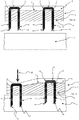
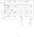
- the device 2 is presented prior to activation and contact with a biological barrier 5.
- the device 2 comprises a flexible substrate 3 having a biological barrier contact surface 4.
- a supplementary layer 6 is provided on the second opposing side 8 of the flexible substrate.
- two micropenetrator arrangements 10 each comprising a head 12 and first and second projections 14, 16.
- the projections extend to a tip 18 and in the form presented are sharpened to a point through cutting the respective projections at an angle non-perpendicular to the longitudinal length of the respective projections.
- the head 12 comprises an abutment surface 20 which may abut the second side 8 of the flexible substrate 3.
- the head 12 is encapsulated within the layer 6.
- the projections 14, 16 project from the first side 4 ready for penetration into the biological layer 5. Such projections may be retained within the flexible substrate 3 adjacent to the first side 4 such that upon application of a force causes the tips 18 to penetrate through the first side 4 and into the biological barrier 5.
- a micro-penetrator arrangement 10 is forced downwardly through the biological barrier 5. Due to the flexibility inherent in the flexible substrate 3 the depth of penetration by micropenetrator 10 is different to an adjacent micropenetrator arrangement. Accordingly, treatment can be tailored to the precise location required. As also shown in Figure 1b , the force applied in the direction indicated by arrow 22 causes the micropenetrator arrangement 10 to enter straight into the biological barrier 5. Side-to-side deflection is minimised due to the provision of the head 12 and plurality of projections 14, 16 extending therefrom. Stability is further improved through the provision of additional projections extending from the head as described in more detail with respect to Figure 2 .
- the flexible substrate 3 is preferably elastomeric as is the supplementary layer 6 if present.
- the force identified in the direction indicated by arrow 22 can be supplied by a roller, a vibrator or any other form of power, and can be used to actuate either a small number of micropenetrator arrangements 10 or a single one. Alternatively, a large number may be activated in parallel or all the micropenetrators in a single device. The micropenetrators may be driven by the force in sequence or at random, and over any time period.
- the head 12 and the first and second projections 14, 16 are beneficially formed of a single piece of material.
- the material is preferably metallic and the first and second projections 14, 16 extend substantially perpendicular to the head 12.
- the micropenetrator arrangement as presented in Figure 1 is in the form of a staple where the projections 14, 16 are of equal length however it will be appreciated that this is not essential.
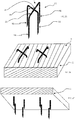
- FIG 2 an exemplary micropenetrator arrangement is presented.
- the micropenetrator arrangement 10 comprises a head 12 in the form of a cross comprising a first arm 26 and second arm 28.
- First and second projections 14, 16 extend from the distal ends of the first arm 26. From the distal ends of the second arm 28 third and fourth projections 30, 32 extend.
- the benefit associated with additional projections extending from the head 12 is the further stability provided. It will be appreciated that a configuration of three or more projections provides improved stability.
- the arms 26, 28 overlap at an overlap zone 34 and are beneficially adhered at this point.
- First and second arms 26, 28 are mutually perpendicular.
- the head 12 can be seen abutting the second side 8 of the flexible substrate 3.
- the projections 14, 16, 30, 32 project through the flexible substrate 3 for penetration into a biological barrier 5.
- the micropenetrator arrangement comprises two projections 14, 16 and head 12. It will be appreciated, however, that such a micro-penetrator arrangement 10 has been presented as an example only and a single projection may be utilised with a head 12. The single projection may be at least partially curved.
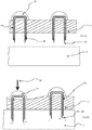
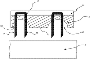
- a formation 36 positioned above the head 12. The formation 36 may be adhered to the head 12 and also to the second side 8 of the flexible substrate 3. The provision of this formation reduces the lateral freedom of movement of the micropenetrator 10.
- the activation sequence is shown pushing the micropenetrator 10 into the biological barrier 5 and shown is the minimal side-to-side deflection of the first and second projections 14, 16.
- the formation 36 protrudes from the second side 8 and in the embodiment shown is in the form of a dome. It will also be appreciated, however, that other shape formations are possible. It will further be appreciated that it is beneficial that the formation 36 comprises a material of higher rigidity than the flexible substrate 3.
- a micro-penetrator arrangement 10 has been shown comprising a configuration of a head 12 and first and second projections 14, 16. It will be appreciated that the head may take a variety of forms and any number of projections may be utilised.
- the head 12 is provided within a layer 40 which is flexible. In the embodiment shown the head 12 is provided within the layer 40 however it will be appreciated that the head 12 may be provided abutting the layer 40 such that the projection(s) extends therethrough.
- a cavity 42 Provided intermediate the layer 40 and the flexible substrate 3 is a cavity 42 that may be filled with a liquid. Channels 44 may extend through the flexible substrate 3 through which the projections extend providing a flowpath through the flexible substrate 3 to the first side 4.
- fluid may travel from the cavity 42 through the channels 44 and into the biological barrier 5. The increase in pressure caused by the force applied as indicated by arrow 22 further pushes the liquid down the channels 44 and into the biological barrier.
- the projections 14, 16 have cavities therein and are provided such that the cavities are in fluid communication with each other via the head 12.
- a formation 36 may be provided as described with respect to Figure 3 to focus pressure and to reduce lateral motion of the micropenetrator within the flexible substrate 3.
- injectates 48 may be solid or liquid or any other formulation.
- Figure 5b shows the device in actuation on a biological barrier such that under the effect of force 22 the projections 14, 16 are driven into the biological barrier. Once there, the injectates dissolve and leave the cavities 46 becoming semi-dissolved particles 50.
- Figure 6 presents a similar embodiment however provided is an additional opening 52 providing access to the cavities.
- the cavity is beneficially open at more than one point to allow a flow of material therethrough.
- injectates 48 are Presented in this embodiment, whilst also applicable to any other embodiment, are formations 36 arranged to be deformable. These may be the same or similar configuration to formations 36 as presented with respect to Figure 3 however in this embodiment the key difference is that they are deformable. Within them there may be a cavity. Accordingly, injectates 48 may be forced from the cavity 46 to enter the biological barrier 5.
- the formation 36 as shown in Figure 6b can be seen to have collapsed thus imparting additional force to the micro-penetrator arrangement 10.
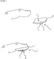
- a flexible substrate 3 having a first side for contacting the biological barrier and a second side 8.
- a micro-penetrator arrangement 10 comprises a head 12 and projecting from the head towards the first side 4 is a projection 14.
- the projection extends from the head to a tip 18 wherein at least a portion of the projection 14 is curved intermediate the head 12 and the tip 18.
- the projection is a repeating curved pattern.
- the curved pattern may be a linear projection twisted to form the final curved configuration.
- the cross-section of the projection 14 may be non-circular. The provision of a curved portion of the projection aids in transfer of a drug or biological material to the biological barrier 5.
- a further supplementary projection may be utilised.
- a supplementary projection may be wrapped around the projection 14 and/or may be intertwined with the projection.
- a supplementary projection may extend from the head.
- a further embodiment is presented whereby the at least one projection 14 is at least partially curved.
- a first and second micro-penetrator 10 may be provided whereby the respective projections are each intertwined.
- supplementary layer 6 is not essential neither is the precise configuration of the micro-penetrator arrangement 10.
- undulations 60 provided in the first side of the flexible substrate 3.
- the biological barrier contact surface is therefore sculpted and is beneficial in delivering liquids or solids applied to the contact surface of the device. This is particularly beneficial, for the purpose of getting an immune response, like an allergy diagnosis patch, or vaccine patch.
- the undulations and thus recesses formed are beneficially provided in the flexible substrate 3 and the one or more projections 14, 16 extend through the recess 60.
- FIG. 10 there is a plan view of an exemplary embodiment of the present invention.
- flexible substrate 3 is shown and layered in parallel with the flexible substrate 3 which effectively forms a first layer is a second layer 70.
- the second layer 70 is layered on top of the first layer.
- the layer 70 carries a plurality of projections projecting into the page as presented in Figure 10 .
- a variety of configurations of projection may be utilised including one or more projections having the form as described in any of the embodiments described herein.
- the projections may be integrally formed with the first layer 70 or as shown in Figure 10 the head 12 is visible. As such the projections extending from the head 12 project through the first layer and through the second layer and subsequently into the biological barrier.
- a plurality of first zones 72 are provided from which a projection extends separated by a plurality of second zones 74.
- the second zones 74 also beneficially comprise a plurality of apertures 74a therein. It is beneficial that the first zones have a greater stiffness than the second zones as this ensures the projections do not deflect laterally upon insertion into a biological barrier and that as force is applied onto the first layer 70 the second zones can bend and flex such that treatment can be applied to the specific areas of the biological barrier as appropriate dependent upon the position of the applied force.
- the second zones may be provided configured to break or fracture upon applied force to enable accurate treatment of specific areas of the biological barrier without significantly impacting upon adjacent areas.
- the device is configured particularly for accommodating the anatomical profile of a fingertip.
- the second side 8 of the substrate 3 is beneficially concave.
- the substrate material 3 is silicone rubber as such a material is readily conformable to the geometry of a fingertip.
- the opposing first side 4 is beneficially convex and in use a finger can be rolled across the skin to contact the projections 14, 16 with the skin to cause penetration.
- the leading edge 8 is curved reflecting the leading edge of a fingertip whereas the trailing edge can be generally linear or curved depending upon particular requirements.
- the one or more projections of a micropenetrator arrangement may have notches, pockets, holes, serrations or undulations therein. Furthermore, they may be coated with other substances, such as another metal. In another embodiment, a projection may have a coating that terminates before reaching the distal end of the projection, such that the projection extends from the coating material. A coating may be provided for example to increase lubricity.
- projections may be positioned sufficiently close to one another so that a material to be administered into the biological barrier may be carried and supported in the separation between the projections.
- the material may be a variety of materials as described elsewhere in the specification including for example a drug.
Landscapes
- Health & Medical Sciences (AREA)
- Engineering & Computer Science (AREA)
- Life Sciences & Earth Sciences (AREA)
- Veterinary Medicine (AREA)
- Public Health (AREA)
- Biomedical Technology (AREA)
- Heart & Thoracic Surgery (AREA)
- Medical Informatics (AREA)
- Animal Behavior & Ethology (AREA)
- General Health & Medical Sciences (AREA)
- Surgery (AREA)
- Hematology (AREA)
- Dermatology (AREA)
- Anesthesiology (AREA)
- Nuclear Medicine, Radiotherapy & Molecular Imaging (AREA)
- Molecular Biology (AREA)
- Medicinal Preparation (AREA)
- Media Introduction/Drainage Providing Device (AREA)
- Containers And Packaging Bodies Having A Special Means To Remove Contents (AREA)
Claims (15)
- Dispositif pour la pénétration d'une barrière biologique, le dispositif comprenant un substrat flexible (3) ayant un premier côté et un second côté opposé, le dispositif comprenant en outre une pluralité d'agencements micropénétrateurs (10) comprenant chacun une tête (12) et des première et deuxième protubérances (14, 16) qui sont destinées à pénétrer une barrière biologique et qui s'étendent depuis la tête, les première et deuxième protubérances (14, 16) s'étendant au moins en partie à travers le substrat flexible (3) vers le premier côté, la tête comprenant un bras allongé (26) écartant les première et deuxième protubérances, le dispositif étant caractérisé en ce que des premier et second agencements micropénétrateurs (10) adjacents sont indépendants l'un de l'autre.
- Dispositif selon la revendication 1, dans lequel le substrat flexible (3) comprend un matériau différent de celui de l'agencement micropénétrateur (10).
- Dispositif selon la revendication 1, dans lequel les première et deuxième protubérances (14, 16) se projettent perpendiculairement à la tête ; et de préférence dans lequel les première et deuxième protubérances (14, 16) se projettent depuis le premier côté.
- Dispositif selon l'une quelconque des revendications précédentes, dans lequel la tête (12) est intégrée et de préférence encapsulée dans le substrat ; et/ou dans lequel le bras (26) et les première et deuxième protubérances (14, 16) sont formés d'un unique élément plié allongé ; et/ou dans lequel la tête (12) et les première et deuxième protubérances (14, 16) sont formées d'un matériau métallique.
- Dispositif selon l'une quelconque des revendications précédentes, dans lequel le bras comprend un premier bras (26) et la tête (12) comprend en outre un second bras, les premier et second bras (26, 28) étant positionnés sous la forme d'une croix ; et de préférence dans lequel les première et deuxième protubérances (14, 16) se projettent depuis le premier bras, et des troisième et quatrième protubérances se projettent depuis le second bras ; et/ou dans lequel les premier et second bras (26, 28) comprennent une zone de chevauchement où se chevauchent les premier et second bras, les premier et second bras (26, 28) étant joints au niveau de la zone de chevauchement ; et/ou dans lequel les premier et second bras sont mutuellement perpendiculaires.
- Dispositif selon l'une quelconque des revendications précédentes, dans lequel le bras allongé est du premier agencement micropénétrateur (10) et est orienté entre la parallèle et la perpendiculaire au bras allongé (28) du second agencement micropénétrateur adjacent ; et/ou dans lequel le substrat comprend du caoutchouc de silicone.
- Dispositif selon l'une quelconque des revendications précédentes, dans lequel des propriétés physiques du substrat sont variables entre le premier côté (4) et le second côté opposé ; et/ou dans lequel le second côté du substrat a un niveau d'adhésion supérieur à celui du premier côté (4).
- Dispositif selon l'une quelconque des revendications précédentes, dans lequel le second côté est concave.
- Dispositif selon l'une quelconque des revendications précédentes, dans lequel le substrat comprend un bord avant et un bord arrière, et le bord avant est incurvé pour se conformer généralement au bord avant d'un doigt.
- Dispositif selon l'une quelconque des revendications précédentes, dans lequel au moins une partie de la première et/ou de la deuxième protubérance comprend une partie incurvée ; et de préférence dans lequel la partie incurvée comprend une pluralité de parties incurvées répétitives.
- Dispositif selon l'une quelconque des revendications précédentes, comprenant une protubérance supplémentaire agencée de sorte qu'au moins une des première et deuxième protubérances soit en communication avec la protubérance supplémentaire pour la pénétration d'une barrière biologique ; et de préférence dans lequel la protubérance supplémentaire est entrelacée avec au moins une des première et deuxième protubérances.
- Dispositif selon l'une quelconque des revendications précédentes, dans lequel les première et deuxième protubérances s'étendent vers une pointe de pénétration (18), au moins une des première et deuxième protubérances comprenant une cavité (42) s'y étendant vers une ouverture adjacente à la pointe ; et/ou dans lequel le premier côté du substrat flexible y porte un médicament et/ou un matériau biologiquement actif ; et/ou dans lequel les première et deuxième protubérances portent un médicament et/ou un matériau biologiquement actif, le matériau y étant de préférence déposé ; et/ou dans lequel la surface du premier côté du substrat flexible est ondulée.
- Dispositif selon l'une quelconque des revendications précédentes, dans lequel le substrat flexible comprend en outre une couche porteuse de micropénétrateur positionnée adjacente au second côté, les première et deuxième protubérances s'étendant depuis la couche porteuse ; et de préférence dans lequel la couche porteuse est plus rigide que le substrat flexible ; et/ou dans lequel les première et deuxième protubérances s'étendent à travers la couche porteuse ; et/ou dans lequel la couche porteuse comprend une matrice.
- Dispositif selon l'une quelconque des revendications précédentes, incluant une formation y définissant une cavité positionnée au-dessus de la tête d'un agencement micropénétrateur.
- Dispositif selon l'une quelconque des revendications 1 à 14, dans lequel le substrat flexible comprend une formation positionnée au-dessus de la tête d'un agencement micropénétrateur, la formation comprenant un matériau dont la rigidité est supérieure à celle du substrat flexible ; et/ou dans lequel le substrat flexible comprend une formation (36) positionnée au-dessus de la tête d'un agencement micropénétrateur (10), la formation (36) faisant saillie par rapport au second côté du substrat flexible.
Applications Claiming Priority (3)
| Application Number | Priority Date | Filing Date | Title |
|---|---|---|---|
| GBGB1420946.4A GB201420946D0 (en) | 2014-11-25 | 2014-11-25 | Flexible device incorporating microperforators |
| GB1517832.0A GB2533839B (en) | 2014-11-25 | 2015-10-08 | Micropenetrator device for penetrating a biological barrier |
| PCT/GB2015/053592 WO2016083803A2 (fr) | 2014-11-25 | 2015-11-25 | Dispositif micropénétrateur pour pénétrer une barrière biologique |
Publications (2)
| Publication Number | Publication Date |
|---|---|
| EP3223899A2 EP3223899A2 (fr) | 2017-10-04 |
| EP3223899B1 true EP3223899B1 (fr) | 2021-07-07 |
Family
ID=52292516
Family Applications (1)
| Application Number | Title | Priority Date | Filing Date |
|---|---|---|---|
| EP15817493.8A Active EP3223899B1 (fr) | 2014-11-25 | 2015-11-25 | Dispositif micropénétrateur pour pénétrer une barrière biologique |
Country Status (11)
| Country | Link |
|---|---|
| US (2) | US10532200B2 (fr) |
| EP (1) | EP3223899B1 (fr) |
| JP (1) | JP6900316B2 (fr) |
| KR (1) | KR20170094253A (fr) |
| CN (1) | CN107223064B (fr) |
| AU (1) | AU2015352176B2 (fr) |
| BR (1) | BR112017010935B1 (fr) |
| GB (2) | GB201420946D0 (fr) |
| RU (1) | RU2017122163A (fr) |
| WO (1) | WO2016083803A2 (fr) |
| ZA (1) | ZA201704235B (fr) |
Families Citing this family (4)
| Publication number | Priority date | Publication date | Assignee | Title |
|---|---|---|---|---|
| JP6760282B2 (ja) * | 2015-07-07 | 2020-09-23 | 凸版印刷株式会社 | 経皮投与デバイス |
| GB201716391D0 (en) | 2017-10-06 | 2017-11-22 | Xobaderm Ltd | Kit for delivery of an active compound into a biological barrier |
| CN111437207A (zh) * | 2020-05-08 | 2020-07-24 | 广州市泫享生物科技有限公司 | 一种具有渗透功能的敷贴式美容贴及其制备方法 |
| FR3129584A1 (fr) * | 2021-11-30 | 2023-06-02 | Pkvitality | Procédé de fabrication d’un module élémentaire d’un capteur à microaiguilles |
Family Cites Families (16)
| Publication number | Priority date | Publication date | Assignee | Title |
|---|---|---|---|---|
| US4966159A (en) * | 1981-12-14 | 1990-10-30 | Maganias Nicholas H | Allergy test strip |
| EP1200140A1 (fr) * | 1999-08-03 | 2002-05-02 | Smith & Nephew, Inc. | Dispositifs implantables a liberation regulee |
| WO2001041863A1 (fr) * | 1999-12-10 | 2001-06-14 | Alza Corporation | Dispositif et procede d'amelioration de percage de peau par micro-protuberances |
| US7828827B2 (en) * | 2002-05-24 | 2010-11-09 | Corium International, Inc. | Method of exfoliation of skin using closely-packed microstructures |
| AU2005243727B2 (en) * | 2004-04-12 | 2011-04-28 | Allergan, Inc. | Multi-site injection system |
| US20070270738A1 (en) * | 2005-04-25 | 2007-11-22 | Wu Jeffrey M | Method of treating ACNE with stratum corneum piercing patch |
| US20070078414A1 (en) * | 2005-08-05 | 2007-04-05 | Mcallister Devin V | Methods and devices for delivering agents across biological barriers |
| WO2007127811A2 (fr) * | 2006-04-25 | 2007-11-08 | Alza Corporation | Application d'un réseau de microsaillies, les microsaillies étant groupées pour accroître la charge médicamenteuse |
| US7785301B2 (en) * | 2006-11-28 | 2010-08-31 | Vadim V Yuzhakov | Tissue conforming microneedle array and patch for transdermal drug delivery or biological fluid collection |
| KR101033514B1 (ko) * | 2009-06-02 | 2011-05-09 | (주)마이티시스템 | 유연한 미세바늘 패치 시스템 및 그 제작방법 |
| JP5860032B2 (ja) * | 2010-04-28 | 2016-02-16 | キンバリー クラーク ワールドワイド インコーポレイテッド | 関節リウマチ薬の送達のためのデバイス |
| US8900616B2 (en) * | 2010-10-22 | 2014-12-02 | Covidien Lp | System and method for satellite drug delivery |
| DE102012014653A1 (de) * | 2012-07-24 | 2014-01-30 | Edelgard Liebl | Vorrichtung zur Behandlung der Haut |
| JP2014097163A (ja) * | 2012-11-14 | 2014-05-29 | Ikeda Kikai Sangyo Kk | マイクロニードルアレイの製造方法 |
| KR101471275B1 (ko) | 2013-02-14 | 2014-12-10 | 주식회사 라온 | 마이크로니들치료기 |
| CN103203072B (zh) * | 2013-03-25 | 2015-05-20 | 清华大学 | 金属微针阵列柔性贴片、经皮给药器件及经皮给药贴片 |
-
2014
- 2014-11-25 GB GBGB1420946.4A patent/GB201420946D0/en not_active Ceased
-
2015
- 2015-10-08 GB GB1517832.0A patent/GB2533839B/en active Active
- 2015-11-25 US US15/528,821 patent/US10532200B2/en active Active
- 2015-11-25 AU AU2015352176A patent/AU2015352176B2/en active Active
- 2015-11-25 KR KR1020177017492A patent/KR20170094253A/ko not_active Application Discontinuation
- 2015-11-25 JP JP2017546053A patent/JP6900316B2/ja active Active
- 2015-11-25 RU RU2017122163A patent/RU2017122163A/ru not_active Application Discontinuation
- 2015-11-25 BR BR112017010935-2A patent/BR112017010935B1/pt active IP Right Grant
- 2015-11-25 CN CN201580074402.9A patent/CN107223064B/zh active Active
- 2015-11-25 WO PCT/GB2015/053592 patent/WO2016083803A2/fr active Application Filing
- 2015-11-25 EP EP15817493.8A patent/EP3223899B1/fr active Active
-
2017
- 2017-06-21 ZA ZA201704235A patent/ZA201704235B/en unknown
-
2019
- 2019-12-13 US US16/713,522 patent/US20200230389A1/en not_active Abandoned
Also Published As
| Publication number | Publication date |
|---|---|
| BR112017010935B1 (pt) | 2022-03-08 |
| JP2017538567A (ja) | 2017-12-28 |
| AU2015352176A1 (en) | 2017-07-13 |
| US10532200B2 (en) | 2020-01-14 |
| JP6900316B2 (ja) | 2021-07-07 |
| GB2533839A (en) | 2016-07-06 |
| GB2533839B (en) | 2020-09-16 |
| BR112017010935A2 (pt) | 2018-02-14 |
| WO2016083803A2 (fr) | 2016-06-02 |
| CN107223064B (zh) | 2021-04-30 |
| RU2017122163A3 (fr) | 2019-06-06 |
| US20170319839A1 (en) | 2017-11-09 |
| AU2015352176B2 (en) | 2020-08-06 |
| CN107223064A (zh) | 2017-09-29 |
| ZA201704235B (en) | 2020-11-25 |
| KR20170094253A (ko) | 2017-08-17 |
| GB201517832D0 (en) | 2015-11-25 |
| GB201420946D0 (en) | 2015-01-07 |
| RU2017122163A (ru) | 2018-12-26 |
| EP3223899A2 (fr) | 2017-10-04 |
| US20200230389A1 (en) | 2020-07-23 |
| WO2016083803A3 (fr) | 2016-07-21 |
Similar Documents
| Publication | Publication Date | Title |
|---|---|---|
| US20200230389A1 (en) | Micropenetrator device for penetrating a biological barrier | |
| EP1326674B1 (fr) | Microstructures permettant de distribuer des compositions de maniere cutanee a la peau | |
| US20110112502A1 (en) | Needleless device for delivery of an agent through a biological barrier | |
| CN101060883B (zh) | 低轮廓微针阵列施放器 | |
| Prausnitz | Microneedles for transdermal drug delivery | |
| KR101708966B1 (ko) | 어플리케이터들에 일체화될 수 있는 내장형 비-경구 지시 장치 | |
| US20060051404A1 (en) | Microstructure roller system | |
| RR Singh et al. | Review of patents on microneedle applicators | |
| EP2946805A1 (fr) | Micro-aiguille, moule pour sa production et son procédé de production | |
| JP2004532698A (ja) | ニードルまたはアブレーダーアレイの操作のための装置 | |
| EP1425064A2 (fr) | Microstructures destinees a distribuer une composition par voie cutanee dans la peau au moyen de structures rotatives | |
| JP2012523265A (ja) | 流体伝達を調節することができるマイクロニードルユニット | |
| WO2011089435A2 (fr) | Dispositif d'administration d'un agent à travers une barrière biologique | |
| KR20120036577A (ko) | 고용체 퍼포레이터 패치의 제조 방법 | |
| KR20210094472A (ko) | 광치료용 니들 패치 및 이의 제조 방법 |
Legal Events
| Date | Code | Title | Description |
|---|---|---|---|
| STAA | Information on the status of an ep patent application or granted ep patent |
Free format text: STATUS: THE INTERNATIONAL PUBLICATION HAS BEEN MADE |
|
| PUAI | Public reference made under article 153(3) epc to a published international application that has entered the european phase |
Free format text: ORIGINAL CODE: 0009012 |
|
| STAA | Information on the status of an ep patent application or granted ep patent |
Free format text: STATUS: REQUEST FOR EXAMINATION WAS MADE |
|
| 17P | Request for examination filed |
Effective date: 20170623 |
|
| AK | Designated contracting states |
Kind code of ref document: A2 Designated state(s): AL AT BE BG CH CY CZ DE DK EE ES FI FR GB GR HR HU IE IS IT LI LT LU LV MC MK MT NL NO PL PT RO RS SE SI SK SM TR |
|
| AX | Request for extension of the european patent |
Extension state: BA ME |
|
| DAV | Request for validation of the european patent (deleted) | ||
| DAX | Request for extension of the european patent (deleted) | ||
| GRAP | Despatch of communication of intention to grant a patent |
Free format text: ORIGINAL CODE: EPIDOSNIGR1 |
|
| STAA | Information on the status of an ep patent application or granted ep patent |
Free format text: STATUS: GRANT OF PATENT IS INTENDED |
|
| RIC1 | Information provided on ipc code assigned before grant |
Ipc: A61B 17/20 20060101ALI20200717BHEP Ipc: A61M 37/00 20060101AFI20200717BHEP Ipc: A61B 17/00 20060101ALI20200717BHEP |
|
| INTG | Intention to grant announced |
Effective date: 20200812 |
|
| GRAS | Grant fee paid |
Free format text: ORIGINAL CODE: EPIDOSNIGR3 |
|
| STAA | Information on the status of an ep patent application or granted ep patent |
Free format text: STATUS: GRANT OF PATENT IS INTENDED |
|
| GRAA | (expected) grant |
Free format text: ORIGINAL CODE: 0009210 |
|
| STAA | Information on the status of an ep patent application or granted ep patent |
Free format text: STATUS: THE PATENT HAS BEEN GRANTED |
|
| AK | Designated contracting states |
Kind code of ref document: B1 Designated state(s): AL AT BE BG CH CY CZ DE DK EE ES FI FR GB GR HR HU IE IS IT LI LT LU LV MC MK MT NL NO PL PT RO RS SE SI SK SM TR |
|
| REG | Reference to a national code |
Ref country code: GB Ref legal event code: FG4D |
|
| REG | Reference to a national code |
Ref country code: AT Ref legal event code: REF Ref document number: 1407957 Country of ref document: AT Kind code of ref document: T Effective date: 20210715 |
|
| REG | Reference to a national code |
Ref country code: DE Ref legal event code: R096 Ref document number: 602015071147 Country of ref document: DE |
|
| REG | Reference to a national code |
Ref country code: IE Ref legal event code: FG4D |
|
| REG | Reference to a national code |
Ref country code: LT Ref legal event code: MG9D |
|
| REG | Reference to a national code |
Ref country code: NL Ref legal event code: MP Effective date: 20210707 |
|
| REG | Reference to a national code |
Ref country code: AT Ref legal event code: MK05 Ref document number: 1407957 Country of ref document: AT Kind code of ref document: T Effective date: 20210707 |
|
| PG25 | Lapsed in a contracting state [announced via postgrant information from national office to epo] |
Ref country code: NO Free format text: LAPSE BECAUSE OF FAILURE TO SUBMIT A TRANSLATION OF THE DESCRIPTION OR TO PAY THE FEE WITHIN THE PRESCRIBED TIME-LIMIT Effective date: 20211007 Ref country code: NL Free format text: LAPSE BECAUSE OF FAILURE TO SUBMIT A TRANSLATION OF THE DESCRIPTION OR TO PAY THE FEE WITHIN THE PRESCRIBED TIME-LIMIT Effective date: 20210707 Ref country code: PT Free format text: LAPSE BECAUSE OF FAILURE TO SUBMIT A TRANSLATION OF THE DESCRIPTION OR TO PAY THE FEE WITHIN THE PRESCRIBED TIME-LIMIT Effective date: 20211108 Ref country code: FI Free format text: LAPSE BECAUSE OF FAILURE TO SUBMIT A TRANSLATION OF THE DESCRIPTION OR TO PAY THE FEE WITHIN THE PRESCRIBED TIME-LIMIT Effective date: 20210707 Ref country code: ES Free format text: LAPSE BECAUSE OF FAILURE TO SUBMIT A TRANSLATION OF THE DESCRIPTION OR TO PAY THE FEE WITHIN THE PRESCRIBED TIME-LIMIT Effective date: 20210707 Ref country code: LT Free format text: LAPSE BECAUSE OF FAILURE TO SUBMIT A TRANSLATION OF THE DESCRIPTION OR TO PAY THE FEE WITHIN THE PRESCRIBED TIME-LIMIT Effective date: 20210707 Ref country code: BG Free format text: LAPSE BECAUSE OF FAILURE TO SUBMIT A TRANSLATION OF THE DESCRIPTION OR TO PAY THE FEE WITHIN THE PRESCRIBED TIME-LIMIT Effective date: 20211007 Ref country code: AT Free format text: LAPSE BECAUSE OF FAILURE TO SUBMIT A TRANSLATION OF THE DESCRIPTION OR TO PAY THE FEE WITHIN THE PRESCRIBED TIME-LIMIT Effective date: 20210707 Ref country code: HR Free format text: LAPSE BECAUSE OF FAILURE TO SUBMIT A TRANSLATION OF THE DESCRIPTION OR TO PAY THE FEE WITHIN THE PRESCRIBED TIME-LIMIT Effective date: 20210707 Ref country code: SE Free format text: LAPSE BECAUSE OF FAILURE TO SUBMIT A TRANSLATION OF THE DESCRIPTION OR TO PAY THE FEE WITHIN THE PRESCRIBED TIME-LIMIT Effective date: 20210707 Ref country code: RS Free format text: LAPSE BECAUSE OF FAILURE TO SUBMIT A TRANSLATION OF THE DESCRIPTION OR TO PAY THE FEE WITHIN THE PRESCRIBED TIME-LIMIT Effective date: 20210707 |
|
| PG25 | Lapsed in a contracting state [announced via postgrant information from national office to epo] |
Ref country code: PL Free format text: LAPSE BECAUSE OF FAILURE TO SUBMIT A TRANSLATION OF THE DESCRIPTION OR TO PAY THE FEE WITHIN THE PRESCRIBED TIME-LIMIT Effective date: 20210707 Ref country code: LV Free format text: LAPSE BECAUSE OF FAILURE TO SUBMIT A TRANSLATION OF THE DESCRIPTION OR TO PAY THE FEE WITHIN THE PRESCRIBED TIME-LIMIT Effective date: 20210707 Ref country code: GR Free format text: LAPSE BECAUSE OF FAILURE TO SUBMIT A TRANSLATION OF THE DESCRIPTION OR TO PAY THE FEE WITHIN THE PRESCRIBED TIME-LIMIT Effective date: 20211008 |
|
| REG | Reference to a national code |
Ref country code: DE Ref legal event code: R097 Ref document number: 602015071147 Country of ref document: DE |
|
| PG25 | Lapsed in a contracting state [announced via postgrant information from national office to epo] |
Ref country code: DK Free format text: LAPSE BECAUSE OF FAILURE TO SUBMIT A TRANSLATION OF THE DESCRIPTION OR TO PAY THE FEE WITHIN THE PRESCRIBED TIME-LIMIT Effective date: 20210707 |
|
| PLBE | No opposition filed within time limit |
Free format text: ORIGINAL CODE: 0009261 |
|
| STAA | Information on the status of an ep patent application or granted ep patent |
Free format text: STATUS: NO OPPOSITION FILED WITHIN TIME LIMIT |
|
| PG25 | Lapsed in a contracting state [announced via postgrant information from national office to epo] |
Ref country code: SM Free format text: LAPSE BECAUSE OF FAILURE TO SUBMIT A TRANSLATION OF THE DESCRIPTION OR TO PAY THE FEE WITHIN THE PRESCRIBED TIME-LIMIT Effective date: 20210707 Ref country code: SK Free format text: LAPSE BECAUSE OF FAILURE TO SUBMIT A TRANSLATION OF THE DESCRIPTION OR TO PAY THE FEE WITHIN THE PRESCRIBED TIME-LIMIT Effective date: 20210707 Ref country code: RO Free format text: LAPSE BECAUSE OF FAILURE TO SUBMIT A TRANSLATION OF THE DESCRIPTION OR TO PAY THE FEE WITHIN THE PRESCRIBED TIME-LIMIT Effective date: 20210707 Ref country code: EE Free format text: LAPSE BECAUSE OF FAILURE TO SUBMIT A TRANSLATION OF THE DESCRIPTION OR TO PAY THE FEE WITHIN THE PRESCRIBED TIME-LIMIT Effective date: 20210707 Ref country code: CZ Free format text: LAPSE BECAUSE OF FAILURE TO SUBMIT A TRANSLATION OF THE DESCRIPTION OR TO PAY THE FEE WITHIN THE PRESCRIBED TIME-LIMIT Effective date: 20210707 Ref country code: AL Free format text: LAPSE BECAUSE OF FAILURE TO SUBMIT A TRANSLATION OF THE DESCRIPTION OR TO PAY THE FEE WITHIN THE PRESCRIBED TIME-LIMIT Effective date: 20210707 |
|
| REG | Reference to a national code |
Ref country code: DE Ref legal event code: R119 Ref document number: 602015071147 Country of ref document: DE |
|
| 26N | No opposition filed |
Effective date: 20220408 |
|
| PG25 | Lapsed in a contracting state [announced via postgrant information from national office to epo] |
Ref country code: MC Free format text: LAPSE BECAUSE OF FAILURE TO SUBMIT A TRANSLATION OF THE DESCRIPTION OR TO PAY THE FEE WITHIN THE PRESCRIBED TIME-LIMIT Effective date: 20210707 |
|
| REG | Reference to a national code |
Ref country code: CH Ref legal event code: PL |
|
| PG25 | Lapsed in a contracting state [announced via postgrant information from national office to epo] |
Ref country code: LU Free format text: LAPSE BECAUSE OF NON-PAYMENT OF DUE FEES Effective date: 20211125 Ref country code: IT Free format text: LAPSE BECAUSE OF FAILURE TO SUBMIT A TRANSLATION OF THE DESCRIPTION OR TO PAY THE FEE WITHIN THE PRESCRIBED TIME-LIMIT Effective date: 20210707 Ref country code: BE Free format text: LAPSE BECAUSE OF NON-PAYMENT OF DUE FEES Effective date: 20211130 |
|
| REG | Reference to a national code |
Ref country code: BE Ref legal event code: MM Effective date: 20211130 |
|
| PG25 | Lapsed in a contracting state [announced via postgrant information from national office to epo] |
Ref country code: LI Free format text: LAPSE BECAUSE OF NON-PAYMENT OF DUE FEES Effective date: 20211130 Ref country code: CH Free format text: LAPSE BECAUSE OF NON-PAYMENT OF DUE FEES Effective date: 20211130 |
|
| PG25 | Lapsed in a contracting state [announced via postgrant information from national office to epo] |
Ref country code: IE Free format text: LAPSE BECAUSE OF NON-PAYMENT OF DUE FEES Effective date: 20211125 Ref country code: DE Free format text: LAPSE BECAUSE OF NON-PAYMENT OF DUE FEES Effective date: 20220601 |
|
| PG25 | Lapsed in a contracting state [announced via postgrant information from national office to epo] |
Ref country code: FR Free format text: LAPSE BECAUSE OF NON-PAYMENT OF DUE FEES Effective date: 20211130 |
|
| PG25 | Lapsed in a contracting state [announced via postgrant information from national office to epo] |
Ref country code: HU Free format text: LAPSE BECAUSE OF FAILURE TO SUBMIT A TRANSLATION OF THE DESCRIPTION OR TO PAY THE FEE WITHIN THE PRESCRIBED TIME-LIMIT; INVALID AB INITIO Effective date: 20151125 |
|
| PG25 | Lapsed in a contracting state [announced via postgrant information from national office to epo] |
Ref country code: CY Free format text: LAPSE BECAUSE OF FAILURE TO SUBMIT A TRANSLATION OF THE DESCRIPTION OR TO PAY THE FEE WITHIN THE PRESCRIBED TIME-LIMIT Effective date: 20210707 |
|
| PGFP | Annual fee paid to national office [announced via postgrant information from national office to epo] |
Ref country code: GB Payment date: 20231129 Year of fee payment: 9 |
|
| PG25 | Lapsed in a contracting state [announced via postgrant information from national office to epo] |
Ref country code: MK Free format text: LAPSE BECAUSE OF FAILURE TO SUBMIT A TRANSLATION OF THE DESCRIPTION OR TO PAY THE FEE WITHIN THE PRESCRIBED TIME-LIMIT Effective date: 20210707 |