EP3223702B1 - Miniaturisierte vorrichtung zur bestimmung eines atmungsmusters - Google Patents
Miniaturisierte vorrichtung zur bestimmung eines atmungsmusters Download PDFInfo
- Publication number
- EP3223702B1 EP3223702B1 EP15816373.3A EP15816373A EP3223702B1 EP 3223702 B1 EP3223702 B1 EP 3223702B1 EP 15816373 A EP15816373 A EP 15816373A EP 3223702 B1 EP3223702 B1 EP 3223702B1
- Authority
- EP
- European Patent Office
- Prior art keywords
- air stream
- physical interface
- less
- capacitive transducer
- sensor element
- Prior art date
- Legal status (The legal status is an assumption and is not a legal conclusion. Google has not performed a legal analysis and makes no representation as to the accuracy of the status listed.)
- Active
Links
Images


Classifications
-
- A—HUMAN NECESSITIES
- A61—MEDICAL OR VETERINARY SCIENCE; HYGIENE
- A61B—DIAGNOSIS; SURGERY; IDENTIFICATION
- A61B5/00—Measuring for diagnostic purposes; Identification of persons
- A61B5/08—Measuring devices for evaluating the respiratory organs
- A61B5/0816—Measuring devices for examining respiratory frequency
-
- A—HUMAN NECESSITIES
- A61—MEDICAL OR VETERINARY SCIENCE; HYGIENE
- A61B—DIAGNOSIS; SURGERY; IDENTIFICATION
- A61B5/00—Measuring for diagnostic purposes; Identification of persons
- A61B5/08—Measuring devices for evaluating the respiratory organs
- A61B5/082—Evaluation by breath analysis, e.g. determination of the chemical composition of exhaled breath
-
- A—HUMAN NECESSITIES
- A61—MEDICAL OR VETERINARY SCIENCE; HYGIENE
- A61B—DIAGNOSIS; SURGERY; IDENTIFICATION
- A61B5/00—Measuring for diagnostic purposes; Identification of persons
- A61B5/08—Measuring devices for evaluating the respiratory organs
- A61B5/0826—Detecting or evaluating apnoea events
-
- A—HUMAN NECESSITIES
- A61—MEDICAL OR VETERINARY SCIENCE; HYGIENE
- A61B—DIAGNOSIS; SURGERY; IDENTIFICATION
- A61B5/00—Measuring for diagnostic purposes; Identification of persons
- A61B5/145—Measuring characteristics of blood in vivo, e.g. gas concentration or pH-value ; Measuring characteristics of body fluids or tissues, e.g. interstitial fluid or cerebral tissue
- A61B5/1468—Measuring characteristics of blood in vivo, e.g. gas concentration or pH-value ; Measuring characteristics of body fluids or tissues, e.g. interstitial fluid or cerebral tissue using chemical or electrochemical methods, e.g. by polarographic means
- A61B5/1477—Measuring characteristics of blood in vivo, e.g. gas concentration or pH-value ; Measuring characteristics of body fluids or tissues, e.g. interstitial fluid or cerebral tissue using chemical or electrochemical methods, e.g. by polarographic means non-invasive
-
- G—PHYSICS
- G01—MEASURING; TESTING
- G01N—INVESTIGATING OR ANALYSING MATERIALS BY DETERMINING THEIR CHEMICAL OR PHYSICAL PROPERTIES
- G01N27/00—Investigating or analysing materials by the use of electric, electrochemical, or magnetic means
- G01N27/02—Investigating or analysing materials by the use of electric, electrochemical, or magnetic means by investigating impedance
- G01N27/22—Investigating or analysing materials by the use of electric, electrochemical, or magnetic means by investigating impedance by investigating capacitance
- G01N27/223—Investigating or analysing materials by the use of electric, electrochemical, or magnetic means by investigating impedance by investigating capacitance for determining moisture content, e.g. humidity
Definitions
- the present invention concerns a device for determining a breathing pattern, and preferably the exhalation pattern of a subject, preferably a human.
- the present invention in particular provides a device allowing the respiratory functions of a subject to be monitored in a real-time fashion, while also permitting to detect abnormal breathing events such as apnea or dyspnea.
- Respiratory monitoring is a widespread medical procedure which finds applications in many domains, from the monitoring of patients undergoing a surgery or suffering from cardio-respiratory diseases, to medical rescue or even sports.
- airflow sensing is probably the more practicable and easier procedure to be implemented to a patient.
- airflow sensing allows measuring several parameters such as temperature, humidity or CO 2 concentration of the inspired and exhaled air.
- respiratory monitoring has long been used for medical applications, there is still a growing demand for cheap devices which enable the monitoring of chosen human life functions in patients, including respiratory ones.
- new measurement methods and new breath monitoring sensors enabling to reduce the manufacturing costs, while at the same time providing more detailed information as to the immediate clinical picture of the patients.
- WO2008/122806 , WO2008/009980 , EP2548505 and US2012/01656693 disclose sensors for detecting water vapor in an exhaled breath. Nevertheless, these sensors are based on metallic electrodes connected together by a porous hydro-sensitive layer. The use of a porous material renders difficult to reach subsecond response times since these materials are enduring a two-step desorption cycle: first the water layer evaporates, then the porous material desorbs. Moreover, porous structures are more sensitive to surface contamination.
- the condensation of the water vapor contained in the breathing air streams on the surface of the sensor element is rapid and do not allow a breathing pattern to be determined.
- the response times of the disclosed transducers are important and do not allow a breathing pattern to be determined in a real-time fashion, especially in wide environmental conditions.
- Said sensors enable to determine a respiratory rate which differs from a full breathing pattern including both the breathing envelope and flux.
- Janik et al. disclose a device for monitoring human breathing, comprising a micro-condensation sensor formed of interdigitated electrodes, wherein said sensor responds to changes in humidity in the form of changes in both capacitance and conductance, even in absence of air flow on the surface.
- a layer allowing water to be absorbed such as an antiseptic layer, strongly enhances the capacity of the sensor to detect micro-condensation under conditions wherein relative humidity is below 80% ( Janik et al., Sens. Act. A, vol. 185 : 160-167, 2012 ).
- the disclosed sensor does nevertheless not allow a breathing pattern, and more specifically an exhalation pattern to be determined in real-time conditions, with a resolving detection of both the very first and very last instants of the exhalation phase.
- the device of the present invention overcomes the above-mentioned drawbacks of the prior art. Indeed, the device of the present invention aims at detecting the deposition of water droplets contained in a breath air stream, and more specifically in an air stream exhaled by a subject, through the combination of an improved sensor element comprising a capacitive transducer, arranged according to a specific angle with respect to the air stream, and of a physical interface possessing a high resolution and an elevated sampling interval frequency.
- the device of the invention is a simple and direct measurement tool providing a reliable, portable and non-intrusive measurement of the respiratory rate.
- the device of the invention thus provides a reliable non-intrusive, quantitative and costsaving solution to a long-felt need. It may be particularly useful for sleep disorder monitoring (especially considering sleep apnea, through apnea and hypopnea detection), as well as to prevent limitation of the revalidation of elderly people due to respiratory impairment, such as for example dyspnea.
- the device of the invention also presents the sensitivity and miniaturization features required for babies and small kids.
- the device of the invention is wireless.
- the present invention thus concerns a method and a device for identifying breathing alterations representative of respiratory troubles or conditions.
- the method for identifying breathing alterations representative of respiratory troubles or conditions comprises:
- the device for implementing the method of the invention comprises:
- the sensor elements and the physical interface are configured for determining a breathing pattern.
- a surface of the sensor elements is exposed to an air stream and forms, in a sagittal plane, an angle comprised between about -30° and about +30° with the said air stream.
- a surface (7) of the sensor elements each comprising said capacitive transducer is exposed to an exhaled air stream and also forms an angle, in a coronal plane, comprised between about -30° and about +30° with the said exhaled air stream.
- the capacitive transducer has a surface area (7) of at least 9 mm 2 .
- the device according to the present invention further comprises:
- At least one temperature sensor element of the device according to the invention is selected in the group consisting of a resistor, a diode or a thermocouple.
- the interdigitated electrodes of the device according to the present invention comprise a metal selected in the group comprising Al, Ni, Au, Ag, Cu, Pt, Pd, Co and Fe or alloys thereof.
- the width of said fingers of said interdigitated electrodes ranges from 1 to 5 ⁇ m and is preferably of about 2 ⁇ m.
- the interdigitated electrodes used in the invention may be referred to as interdigitated microelectrodes.
- the width of said interspaces extending between the fingers of said interdigitated electrodes ranges from 1 to 5 ⁇ m and is preferably of about 2 ⁇ m.
- the dielectric material of the said isolating support is selected in the group consisting of ceramic, glass, polymers or the like, and is preferably silicon oxide.
- the said physical interface of the device according to the invention is selected in the group comprising a Schmitt trigger, a Ring oscillator, a Sigma-delta analog-to-digital converter (ADC), a C-2C Analog-to digital converter and a constant DC charge current scheme for capacitance measurement.
- ADC Sigma-delta analog-to-digital converter
- C-2C Analog-to digital converter a constant DC charge current scheme for capacitance measurement.
- the said physical interface of the device according to the invention has a sampling interval frequency of less than 500 Hz, or less than 200 Hz, or about or less than 100 Hz.
- the interval frequency is about 100 Hz (period is 10 ms).
- the said physical interface of the device according to the invention has a resolution of about or less than 1 fF.
- the surface area of said capacitive transducer of the device according to the invention is equal or greater than 16 mm 2 , and preferably equal or greater than 25 mm 2 .
- the device according to the invention further comprises:
- the present invention further comprises a device as described hereinabove for use for establishing the breathing pattern of a subject.
- the said device is for use for detecting abnormal patterns in the respiratory functions of a subject.
- the said subject is a mammal, and preferably a human.
- This invention thus relates to a method according to claims 1 to 14 and a device according to claim 15.
- the sensor elements and the physical interface of the device of the invention are configured for determining a full breathing pattern.
- the said air stream corresponds to a breathed air stream, preferably to an inhaled and/or exhaled air stream and more preferably to an exhaled air stream.
- the said air stream corresponds to a nasal and/or oral air stream.
- the said air stream corresponds to an air stream inhaled and/or exhaled by one nostril, by both nostrils, by mouth and/or by a combination thereof.
- the said breathed air stream is generated by a mammal, preferably a human or an animal.
- the water sensor element according to the invention has a minimal detection capacity of at least 10 deposited water droplets, preferably of at least 15 deposited water droplets. In a particular embodiment, the minimal detection capacity of the water sensor element according to the invention is of about 20 deposited water droplets.
- the device of the invention comprises two or three sensor elements.
- the said device comprises two sensor elements, which are preferably disposed such that each sensor element is exposed to the air stream flowing through one nostril.
- a device according to the invention comprising two sensor elements allows the air stream of both nostrils to be analyzed simultaneously and independently.
- the device according to the invention allows the water droplet content of the air stream inhaled and/or exhaled by both nostrils to be determined and analyzed, while simultaneously tolerating a normal mouth breathing of the subject.
- the said device comprises one sensor element, which is preferably disposed such as to be exposed to the air stream inhaled and/or exhaled by the mouth.
- the device of the invention comprises three sensor elements, wherein two sensors elements allow the air stream of each nostril to be analyzed independently, and the third sensor allows the air stream of the mouth to be analyzed.
- the sensor element according to the invention comprises a capacitive transducer formed by interdigitated electrodes.
- capacitive transducer it is meant an electrical system wherein an electrical charge is applied between two conductive objects (hereinafter the “electrodes”), separated one from each other by a gap (hereinafter “the interspace”).
- the capacitive transducer for use in the present invention is capable to sense its environment in the form of capacitor changes. The said capacitive transducer thus allows a water droplet placed between the electrodes to be detected.
- the capacitive transducer for use in the invention more specifically comprises a plurality of electrode portions arranged in the form of an array of interdigitated electrode portions, for instance arranged in a concentric or rectangular pattern.
- Such capacitive transducers are well known to the skilled person in the art and are also referred to as interdigitated electrodes (or "ITE"). Within the meaning of the invention, the term “fingers” refers to the isolated portions of electrodes that are interdigitated.
- the electrodes for use in the capacitive transducer according to the invention may be formed by any suitable technique.
- the technique comprises printing the electrode material in the form of a thick film screen printing ink onto an isolating support.
- Alternative techniques for preparing the electrodes and applying them to an isolating support include spin/sputter coating and visible/ultraviolet/laser photolithography.
- the electrodes may also be prepared by electrochemical plating ("electroplating").
- each electrode may comprise a plurality of layers applied by different techniques.
- the electrodes for use in a capacitive transducer as shown in Figure 1 may be formed of any material suitable for capacitive transduction.
- material suitable for capacitive transduction it is meant that the said electrodes are formed in a material allowing an electric, and more specifically a capacitive, transduction to be formed, more specifically upon linking both electrodes by water droplets.
- materials suitable for capacitive transduction according to the present invention include metallic materials, and are preferably selected in the group consisting in Al, Ni, Au, Ag, Cu, Pt, Pd, Co, Fe or alloys or combinations thereof.
- the electrodes of the capacitive transducer are formed of Al or alloys thereof.
- the thickness of the electrodes for use in capacitive transducer according to the present invention is determined by the manufacturing technology, but has no direct influence on the capacitive detection.
- the thickness of the electrodes ranges from 100 nm to 900 nm, and is preferably of about 500 nm.
- the capacitive transducer according to the present invention is such that the width (4) of the electrode fingers forming the interdigitated electrode ranges from 0.5 to 10 ⁇ m, and is preferably of about 2 ⁇ m.
- the capacitive transducer according to the present invention is also such that the width (3) of the interspaces extending between the electrode fingers forming the interdigitated electrode ranges from 0.5 to 10 ⁇ m, and is preferably of about 2 ⁇ m.
- the width (4) of the electrode fingers (1) and the width (3) of the interspaces (2) extending between said electrode fingers (1) are substantially equivalent, and are preferably of about 2 ⁇ m.
- Such respective width (3,4) for the fingers (1) and the interspaces (2) of the interdigitated electrodes used in the device of the invention advantageously allow deposited water droplets to be detected as from a minimal deposition of at least 10, preferably at least 15 and more preferably of about 20 water droplets on the surface of the capacitive transducer.
- Water droplets suspended in an inhaled and/or exhaled air stream are indeed known to have a mean diameter of from about 2 ⁇ m to about 20 ⁇ m.
- the respective widths (3,4) of the electrode fingers (1) and interspaces (2) used in the device of the present invention is especially selected for allowing variations of the capacitive transduction to be detected between two electrode fingers as a result of water droplet deposition.
- a reliable detection of the water droplets deposition on the surface of the capacitive transducer of the invention requires the cumulative alterations of capacitive transduction resulting from as few as at least 10, preferably at least 15, more preferably of about 20 water droplets to be detected.
- This detection capacity thus renders possible, for the device of the invention, to detect the onset of the exhalation phase with a very high precision, and thus contribute to the capacity of said device to acquire data relating to the full breathing envelope of a subject, and thus to identify breathing alterations that are representative of respiratory troubles or conditions.
- the portions of the electrodes that are not disposed to be in contact with the air stream may be coated with a dielectric material, patterned in such a way as to leave exposed the active portions of the electrodes.
- the sensor element according to the invention further comprises an isolating support formed by a dielectric material.
- the interdigitated electrodes forming the capacitive transducer of the invention are plated onto the said isolating support.
- the said isolating support may thus be formed by any suitable material, provided that it does not react or interact with the electrodes or with the water droplets suspended the air stream to be analyzed.
- the said isolating support is formed of a non-conductive material, for example ceramic, glass, polymers (e.g. plastics) or the like.
- the said isolating support is formed of oxides, in particular metal oxides, including aluminium oxide, silicon oxide, titanium oxide, zirconium oxide and mixtures thereof.
- the said isolating support is formed of a silicon oxide or a silicon dioxide.
- the isolating support is made of a ceramic material such as Si 3 N 4 .
- the capacitive transducer for use in the device of the invention has a surface area of at least 4mm 2 .
- the surface area of the capacitive transducer of the invention is equal or greater than 9 mm 2 .
- the surface area of said capacitive transducer is equal or greater than 16 mm 2 .
- the surface area of said capacitive transducer is equal or greater than 25 mm 2 .
- the present inventors have indeed surprisingly discovered that a minimal surface area of 4 mm 2 is required for allowing the full breathing envelope to be determined, in avoiding saturating the detection capacity of the said device, and more specifically of the capacitive transducer.
- water droplets in suspension in an air stream start to be deposited on the surface of the sensor element according to the invention when the device is exposed to the said air stream.
- a similar situation occurs when the device according to the invention is exposed to a starting exhalation air stream in a subject.
- the water droplets deposited on the surface of the capacitive transducer are being detected as from 10, preferably as from 15 and more preferably as from 20 droplets and induce a first signal variation of the capacitive transduction. This phenomenon amplifies as the exhalation progresses, since an increasing number of water droplets are depositing on the surface of the capacitive transducer.
- the accumulation of the deposited water droplets leads to their progressive aggregation, for forming large water drops, then for forming a water film.
- the water film formed at the surface of the capacitive transducer at the end of the exhalation phase generally leads to the saturation of the transduction signal in the respiratory monitoring devices known in the art.
- the present inventors have nevertheless surprisingly discovered that a capacitive transducer according to the present invention and having a minimal surface area of 4 mm 2 is not saturated by the accumulated water droplets deposited along a full exhalation phase. It therefore results that the device of the invention now renders it possible to acquire the complete information relating to the breathing envelope of a subject, and thus overcomes the drawbacks encountered with respiratory monitoring devices known in the art.
- the surface area of the capacitive transducer used in the device of the invention is such that the water film formed at the end of the exhalation phase is fully evaporated during the subsequent inhalation phase. This property allows the device of the invention to acquire data relating to the breathing process in a real-time fashion.
- the sensor element according to the invention is in particular such that the materials used for forming the electrodes of the capacitive transducer or the isolating support are not absorbing water molecules.
- the resolution and the dynamics of the said sensor are therefore not affected by the absorption/desorption of water, such as observed in several respiratory monitoring systems known in the art.
- the device of the invention further comprises a physical interface suitable for transducing a capacitive signal obtained from the sensor elements into an analog or digital signal.
- the said capacitive interface is capable to transduce the capacitance value obtained from the sensor element into a voltage, current, frequency, time or any other digital value proportional to the measured capacitance value.
- the physical interface for use in the device of the invention has a sampling interval frequency of less than 500 Hz, or less than 200 Hz, or about or less than 100 Hz.
- the said physical interface has a sampling interval period of about 50 ms or less, more preferably of about 20 ms or less, preferably of about 10 ms or less.
- the sampling interval period of said physical interface ranges from 1 ms to 128 ms, preferably from 10 ms to 100 ms, more preferably from 10 ms to 50 ms.
- the sampling interval frequency of the physical interface for use in the device of the present invention renders it possible to acquire a large number of capacitive signals issued by the sensor element along the inhalation and exhalation phases of the breathing process.
- the high sampling interval frequency of the physical interface of the invention thus participates to the capacity of the device of monitoring the breathing envelope of a subject in a real-time fashion, with a very high resolution.
- the physical interface for use in the device of the invention has a capacitance resolution of about less than 10 pF.
- the said physical interface has a capacitance resolution of less than 10 pF, preferably of less than 1pF and more preferably of about 0.01 pF.
- the capacitance resolution of the physical interface of the invention ranges from about 0.01 pF to about 10 pF, and preferably from about 1 pF to about 5 pF.
- the capacitance resolution of the physical interface for use in the device of the invention thus participates to the capacity of the said device to detect as few as from 10 deposited water droplets, preferably as few as from 15 deposited water droplets and more preferably as few as about 20 deposited water droplets on the surface or the sensor element exposed to the air stream.
- the resolution of the physical interface (the smallest change that a sensor can detect) differs from the sensibility of the physical interface (minimum change of input signal required to produce a specified output signal).
- the said physical interface is selected in the group comprising a Schmitt trigger, a Ring oscillator, a Sigma-Delta analog-to-digital converter (ADC), a C-2C Analog-to digital converter and a constant DC charge current scheme for capacitance measurement.
- the said physical interface is a constant DC charge current scheme for capacitance measurement, wherein the charging time and the value of the charge current are able to be reprogrammed during operation (i.e. "on fly"), thus allowing the dynamics of the voltage accumulated in the capacity to be optimized.
- the physical interface is a constant DC charge current scheme for capacitance measurement such as a MPR121 physical interface (Freescale Semiconductor Inc.).
- the physical interface may have a range of capacitance of from 10 pF to 2000 pF.
- the physical interface may have a range of capacitance of from one unit to at least 100 times this unit (for example from 1 pF to 100 pF).
- the physical interface for use in the device of the invention has the capacity of being reprogrammed during the acquisition of capacitive data issued by the sensor element.
- the said physical interface is indeed advantageously capable of monitoring the voltage of the capacitive transducer of the sensor element and to modify, where necessary, the value of the charge/discharge current and/or the value of the charge/discharge time to ensure the best dynamic response of the sensor element.
- the physical interface can dynamically modify the value of the time charge/discharge and/or the value of the charge/discharge current if electrode data goes out of valid range during the measurement, and this to ensure a maximal resolution of the sensor measurements.
- sampling interval frequency and/or period of the said physical interface can thus be modified in a real-time fashion for ensuring that the detection thresholds of capacitive variations are in adequation with the capacitive signal issued by the sensor element.
- the said sensor elements are directly exposed to an air stream.
- the air stream is not directed to the sensor by means of any suction pipe.
- the device of the invention is further such that the side angle between the surface of the water sensor element exposed to the said air stream and the air stream is comprised between -30° and +30°.
- side angle it is meant the angle formed by the surface of the water sensor element, comprising the capacitive transducer, which is exposed to the said air stream and the average mean directional jet of the air stream, as visualized on a side view of the air stream, i.e. as visualized on a sagittal section thereof (see for instance Figure 2 ).
- the determination of a breathing pattern based on the deposition of the water droplets contained in the said air stream requires that at least whole or part of the sensor element be placed within the side spreading angle of the measured air stream jet (6).
- the surface (7) of the sensor element comprising said capacitive transducer is exposed to an exhaled air stream and forms an angle, in a sagittal plane, comprised between about -30° and about +30° with the said exhaled air stream, or between about -29° and about +29°, or between about -28° and about +28°, or between about -27° and about +27°, or between about -26° and about +26°, or between about -25° and about +25°, or between about -24° and about +24°, or between about -23° and about +23°.
- sagittal plane refers to a vertical plane which passes from anterior to posterior, dividing the body into right and left halves.
- the surface (7) of the sensor element comprising said capacitive transducer is exposed to an exhaled air stream and forms an angle, in a coronal, comprised between about -30° and about +30° with the said exhaled air stream, or between about - 29° and about +29°, or between about -28° and about +28°, or between about -27° and about +27°, or between about -26° and about +26°, or between about -25° and about +25°, or between about -24° and about +24°, or between about -23° and +23°, or between about -22° and about +22°, or between about -21° and about +21°.
- coronal plane refers to a vertical plane that divides the body into ventral and dorsal sections and containing the nostrils.
- the side angle between the surface of the sensor element exposed to the said air stream and the air stream is comprised between -30° and +30°.
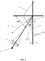
- side angle it is meant the angle formed by the surface of the sensor element exposed to the said air stream and the average mean directional jet of a nostril air stream, as visualized on a sagittal section of the head (see Figure 3 ).
- the average mean directional jet of a nostril air stream is considered as forming a side angle of 60° ⁇ 6° with the horizontal, as shown on Figure 3 (see also Gupta et al., “Characterizing exhaled air flow from breathing and talking", Indoor Air, 2010, 20:31-39 ).
- At least whole or part of the sensor element has to be placed within the side spreading angle of 23° ⁇ 14° of the measured air stream jet (6) as shown on Figure 3 .
- the side angle between the surface of the sensor element exposed to the said air stream and the air stream is comprised between -30° and +30°.
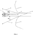
- side angle it is meant the angle formed by the surface of the water sensor element exposed to the said air stream and the average mean directional jet of a mouth air stream, as visualized on a sagittal section of the head (see Figure 4 ).
- the average mean directional jet of a mouth air stream is considered as being substantially horizontal, as shown on Figure 5 (see in particular Gupta et al., “characterizing exhaled air flow from breathing and talking", Indoor air, 2010, 20:31-39 ).
- At least whole or part of the water sensor element has to be placed within the side spreading angle of 30° (corresponding to the sum of the angles ⁇ 1 and ⁇ 2 on Figure 4 ) of the measured mouth air stream jet (6) as shown on Figure 4 .
- the exhaled air stream has the shape of a cone and the surface (7) of the sensor element comprising said capacitive transducer is exposed to the exhaled air stream and forms with respect to the height of the cone an aperture angle comprised between about -30° and about +30° with the said exhaled air stream, or between about - 29° and about +29°, or between about -28° and about +28°, or between about -27° and about +27°, or between about -26° and about +26°, or between about -25° and about +25°, or between about -24° and about +24°, or between about -23° and about +23°.
- the device according to the present invention differs from the respiratory sensing devices known in the art at least in that it does not rely on the monitoring of the condensation of the vapored water contained in the breathed air stream.
- the device of the present invention does indeed contain no porous or mesoporous film of ion exchange material extending between the electrode fingers.
- the resolution and the dynamics of the device of the present invention are not affected or altered by the possible condensation of the water vapor contained in the breathing air streams on the surface of the sensor element.
- the condensation of the water vapor contained in the breathing air streams on the surface of the sensor element is regarded as negligible when compared to the deposition of water droplets suspended in the said air streams.
- the water vapor contained in the exhaled air stream may condense importantly on the surface of the sensor element and may then affect the determination of capacitive variations along the exhalation phase.
- the device according to the present invention when the device according to the present invention is operated in conditions wherein the external residual humidity is lower than 40% or wherein the external temperature is above 35°C, the water droplets suspended in the exhaled air stream may evaporate rapidly after their deposition of the surface of the sensor element, thus possibly altering the determination of capacitive variations along the exhalation phase. In such conditions, there is therefore a need for that the temperature of the surface of the sensor element be maintained in a range rendering it possible to be used without being affected by the external relative humidity or temperature.
- the device according to the invention thus further comprises at least one temperature sensor element, disposed for measuring the temperature of the surface of the sensor element exposed to the air stream, and means for heating and/or cooling the surface of the water sensor element exposed to the air stream.
- the said temperature sensor element may be formed of an additional electrode.
- the means for measuring the temperature of the surface of the sensor element exposed to the air stream are selected in the group consisting of a resistor, a diode or a thermocouple.
- the means for heating may comprise a microheater and the means for cooling may comprise a microcooler, such dispositives being known in the art.
- the said means for heating and/or cooling the surface of the sensor element can thus be used to control the temperature of the surface of the sensor element exposed to the air stream such that this temperature is maintained in a range of from -10% to +10% around the dew point temperature of the water vapor contained in the said air stream.
- dew point temperature it is meant the temperature at which the water vapor starts to condense out of the air, i.e. the temperature at which saturation is reached when the moisture of air remains constant. Above this temperature, the moisture stays in the air.
- the expressions "dew point temperature” or “condensation temperature” are used as synonyms.
- the dew point temperature of the water contained in the air stream depends from the temperature of the said air stream, from the temperature of the surface of the sensor element exposed to the air stream, from the humidity content in the air stream and of the atmospheric pressure of the location where the device of the invention is operated.
- the dew point temperature may be measured and/or calculated by any method known in the art including enthalpy/entropy diagrams or charts, psychrometric diagrams and the like.
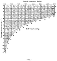
- the dew point temperature of the water contained in the air stream is measured through the use of a Mollier diagram, preferably a Mollier diagram displaying the dry bulb temperature as a function of humidity, as a function of enthalpy.
- the Mollier diagram used is displaying the dry bulb temperature as a function of specific humidity, as a function of enthalpy, such as that represented in Figure 5 .
- the device according to the invention may further comprise control means suitable for receiving an input analog or digital signal from the said physical interface.
- control means of the device of the invention allows the electric signal associated to the capacitance variation to be set to a maximal value when the capacitance in minimal (dry surface) and a minimal value when the capacitance is maximal (when the deposition of water droplets on the surface of the sensor element is maximal, i.e. when at the end of exhalation phase).
- the measurement range is maximal leading to an optimal display of the breathing envelope, facilitating the visualization of small nasal flows volume.
- the said control means are not physically localized with the sensor element and can be positioned remotedly.
- the device according to the invention further comprises means for recording and/or transmitting and/or displaying data received by the control means.
- the device of the invention comprises means for transmitting the data, such as for instance a radio emitter capable to transmit data to a suitable receiver by radio.
- the said means for transmitting data include wireless data transfer means, and more particularly transmitting means that are compatible with low energy communication transmission protocols standards ZigBee ® or Bluetooth ® .
- the said means for transmitting data include USB interfaces such as micro USB interfaces.
- the device of the invention comprises means for recording electronical data, such as flash memory or microSD.
- the device of the invention further comprises means for displaying the data corresponding to the variations of water droplets deposition measured in the course of the breathing.
- displaying means may for instance include an oscilloscope, light-emitting diodes (LEDs) or any other suitable displaying mean.
- the variations of water droplets deposition on the surface of the sensor element, for instance during the inhalation and/or exhalation cycles may thus be directly visualized in real-time, for instance with brightness intensity varying according to the output sensing signal.
- the device of the invention comprises both recording and transmission means and further optionally comprises displaying means.
- the device of the invention may further comprise light-emitting diodes (LEDs) or the like for system calibration and/or visual monitoring.
- LEDs light-emitting diodes
- the said control means also receive input data from the said temperature sensor element(s), and send input data to the means for heating and/or cooling.
- the control means thus allows data generated by the sensor element and the temperature sensor element to be collected such as to generate the heating or the cooling of the sensor area for allowing the temperature of the surface of the sensor element to be maintained within a suitable range for allowing the determination of the breathing pattern to be operated adequately.
- the device according to the invention may further comprise a housing element comprising said sensor element, and disposed such that the angle between the surface of the sensor element to be exposed to the air stream and the air stream is comprised within the hereinabove listed side angle values.
- the housing element for use in the device of the invention is indeed such that the orientation of the surface of the sensor element is defined in order to optimize both water droplet deposition during the exhalation phase and forced drying of the capacitive transducer surface during the inhalation phase.
- the housing element is such that the angle between the surface of the sensor element to be exposed to the air stream and the philtrum of the subject (i.e.
- the vertical groove in the middle area of the upper lip, common to many mammals, extending from the nose (8) to the upper lip (14)) is comprised between 0° and 60°, preferably between 10° and 50°, preferably between 20° and 40°, preferably between 25° and 35°; and is more preferably of 30°.
- the housing element also comprises said at least one temperature sensor element, said means for heating and/or cooling, said physical interface, said control means and said means for storing and/or transmitting and/or displaying data.
- the housing element of the device of the invention is mountable on the upper lip of a subject.
- the said housing comprises apertures allowing the sensor element to be in direct contact with the air stream of the subject.
- the said housing element may further comprise an open ended conduit extending longitudinally between the mouth and the nose of a subject, or under the mouth of a subject, such that the nasal or mouth air stream of the subject is channeled to a surface of the water sensor element.
- the device of the present invention is compatible with a nasal cannulae.
- the said housing element is mountable on a tubular conduit or a cannulae connected to the mouth and/or to the nostrils of the subject, and allows the surface of the sensor element to be exposed to the air stream circulating inside the conduit/cannulae to be positioned according to the side angle requirements discussed above.
- the body or housing of the device is prepared from a non-conductive material, such as a suitable plastic.
- the device according to the invention may further comprise a power supply.
- the power supply is a battery.
- the device of the invention thus allows a breathing pattern to be determined, and more specifically directly allows the duration and the frequency of the exhalation phase to be determined in a real-time fashion.
- the said device of the invention may thus be used for acquiring a real-time breathing frequency or duration of a subject during a physical exercise or at rest.
- the device of the invention is useful in domains such as elderly rehabilitation, sudden infant death monitoring, sport training and sleep disorder early diagnosis and/or monitoring.
- the device of the invention allows pathological breathing patterns to be identified.
- Such pathological breathing patterns include more particularly bradypnea, characterized by slow respirations, tachypnea, characterized by a respiratory rate increase, hyperventilation, characterized by an increase in respiratory rate or tidal volume, or both, Kussmaul respirations, characterized by deep respirations with fast, normal or slow rate, Cheyne-Stokes, characterized by waxing and waning with periods of apnea between a repetitive pattern, apneusis, characterized by sustained maximal inhalation with pause, Biot's respiration, characterized by irregular periods of apnea alternating with periods in which four or five breaths of identical depth are taken, or ataxic patterns, characterized by irregular and unpredictable pattern with periods of apnea.
- the device according to the invention does nevertheless not allow to quantify the volumes of air inhaled and/or exhaled and could therefore not be implemented for determining breathing volumes.
- the device of the invention allows for a real-time display of the breathing frequency of people during a physical exercise or at rest.
- the device of the invention is useful in domains such as elderly rehabilitation, sudden infant death monitoring, sport training and sleep disorder early diagnosis and/or monitoring.
- the device according to the invention may thus be implemented for monitoring and determining the respiratory rate and envelope of breathing of a subject, in particular a mammal, such as a human subject or an animal.
- the device is particularly useful for applications requiring fast response times, for example personal respiratory monitoring of patients undergoing surgery.
- the device according to the present invention may further be generally used in the field of respiratory medicine, airway diseases, both restrictive and obstructive, airway tract disease management, and airway inflammation.
- the present invention finds particular application in the field of monitoring and management of airway diseases (such as asthma).
- the results may be used to provide an early alert to the onset of respiratory diseases or illness.
- the device according to the invention is advantageously easily fabricated from low-cost materials and is adaptable for use in various medical environments, and for the monitoring of various medical conditions.
- the device of the invention is particularly suitable for use in hospital and primary healthcare, especially for critical patients.
- the device of the invention further finds its use in the monitoring of a subject suffering from respiratory impairment, especially sleep apnea.
- the ability of measuring the full breathing envelope in the exhaled air stream of a subject or animal may also be used in the diagnosis of Adult Respiratory Distress Syndrome (ARDS), and end-stage life-threatening lung disease.
- ARDS Adult Respiratory Distress Syndrome
- the device according to the invention is particularly useful for applications requiring fast response times (e.g. requiring subsecond response times), for example personal respiratory monitoring of tidal breathing (capnography).
- Capnographic measurements can be applied generally in the field of respiratory medicine, airway diseases, both restrictive and obstructive, airway tract disease management, where the shape of the capnogram changes as a function of the extent of the disease.
- the device of the invention is used simultaneously or sequentially with a means for measuring cardiac rhythm, arterial pressure and/or SpO2.
- the present invention is further illustrated by the following example.
- a device having the general configuration shown in Figures 1-3 was prepared for measuring the nasal breathing of healthy subjects and of subjects suffering from respiratory troubles.
- the device used for these experiments comprised 2 sensor elements, wherein the electrodes are in Aluminum and the isolating support is made of silicon oxide.
- the width (4) of the fingers of the electrodes is of 2 ⁇ m and the width (3) of the interspace (2) between the electrodes is of 2 ⁇ m.
- Each sensor element for use in the said device had a surface area (7) of 9 mm 2 .
- the said sensor elements were placed in a housing designed for monitoring the nasal breathing of human subjects such that each sensor element is placed in the air stream of one nostril.
- the said sensor elements were operatively connected to a physical interface MPR121 (Freescale Semiconductor Inc.).
- the side angle formed between each average mean directional nostril air stream and the surface (7) of each sensor element exposed to the air stream was of about 0° (i.e. the surface (7) of each sensor element was substantially parallel to the average mean nostril air stream).
- the device further comprised one physical interface, as well as control means and transmitting means.
- the tests were conducted under regular atmospheric pressure (i.e. about 1013.25 hPa), at room temperature (i.e. at about 20°C).
- the nasal air stream of the tested subjects was shown to have a temperature of about 34-36°C and a relative humidity of about 50-60%.
- the breathing of the subjects was measured at rest, then they were instructed to have a walk for 5 to 15 minutes. After the walk, the subjects were requested to rest again and the recovery parameters were also measured.
- the collected data demonstrate that the envelope and flux of the breathing could be measured in real-time, during the physical exercise as well as at rest.
- the collected data were processed by a computer and the corresponding capnograms were prepared (see Figure 6 A, B and C ).
- the general pattern expected of a healthy subject is obtained with the device of the invention.
- the resulting capnograms further demonstrate that not only the device of the invention allows the breathing envelope of the subject to be measured in real-time, but it also allows data to be collected without observing any saturation of the sensor element.
Landscapes
- Health & Medical Sciences (AREA)
- Life Sciences & Earth Sciences (AREA)
- Pulmonology (AREA)
- Biomedical Technology (AREA)
- Medical Informatics (AREA)
- Biophysics (AREA)
- Pathology (AREA)
- Engineering & Computer Science (AREA)
- Physiology (AREA)
- Heart & Thoracic Surgery (AREA)
- Physics & Mathematics (AREA)
- Molecular Biology (AREA)
- Surgery (AREA)
- Animal Behavior & Ethology (AREA)
- General Health & Medical Sciences (AREA)
- Public Health (AREA)
- Veterinary Medicine (AREA)
- Investigating Or Analyzing Materials By The Use Of Electric Means (AREA)
Claims (15)
- Verfahren zum Identifizieren von Atemveränderungen, die Atembeschwerden oder Atemwegserkrankungen repräsentieren, umfassend:(a) Bereitstellen einer Vorrichtung, die umfasst:(i) zwei oder drei Sensorelemente, die jeweils aus Folgendem bestehen:- einer isolierenden Stütze, die durch ein dielektrisches Material gebildet wird; und- einem einzelnen kapazitiven Wandler, der durch ineinandergreifende Elektroden gebildet wird,wobei die Fingerbreite (3) der ineinandergreifenden Elektroden von etwa 0,5 bis etwa 10 µm reicht;wobei der Zwischenraum (2), der sich zwischen den Fingern der ineinandergreifenden Elektroden erstreckt, eine Breite (3) aufweist, die von etwa 0,5 bis etwa 10 µm reicht;wobei der kapazitive Wandler eine Oberflächenfläche (7) von mindestens 4 mm2 aufweist;wobei die Materialien der Elektroden oder der isolierenden Stütze keine Wassermoleküle absorbieren;(ii) eine physische Schnittstelle, die zum Umsetzen eines kapazitiven Signals, das von den Sensorelementen erhalten wird, in ein analoges oder digitales Signal geeignet ist;wobei die physische Schnittstelle eine Abtastintervallfrequenz von weniger als 500 Hz oder weniger als 200 Hz oder etwa oder weniger als 100 Hz aufweist, undwobei die Schnittstelle eine Auflösung von etwa oder weniger als 0,1 pF, vorzugsweise etwa oder weniger als 0,01 pF aufweist;(b) Platzieren der Vorrichtung, sodass eine Oberfläche (7) der Sensorelemente, die den kapazitiven Wandler umfassen, einem ausgeatmeten Luftstrom ausgesetzt wird und mit dem ausgeatmeten Luftstrom einen Winkel in einer Sagittalebene zwischen etwa -30° und etwa +30° bildet;wobei die Sensorelemente und die physische Schnittstelle zum Bestimmen einer Atemfrequenz und Atemhülle konfiguriert sind; undwobei die Sensorelemente konfiguriert sind, Wassertröpfchen, die in dem ausgeatmeten Luftstrom schweben, während sie sich auf der Oberfläche des kapazitiven Wandlers absetzen, zu unterscheiden und/oder zu zählen.
- Verfahren nach Anspruch 1, wobei der kapazitive Wandler eine Oberflächenfläche (7) von mindestens 9 mm2 aufweist.
- Verfahren nach Anspruch 1 oder 2, wobei eine Oberfläche (7) der Sensorelemente, die den kapazitiven Wandler umfassen, einem ausgeatmeten Luftstrom ausgesetzt wird und mit dem ausgeatmeten Luftstrom einen Winkel in einer Koronalebene zwischen etwa -30° und etwa +30° bildet.
- Verfahren nach einem der Ansprüche 1 bis 3, wobei die Vorrichtung ferner umfasst:(a) mindestens ein Temperatursensorelement, das zum Messen der Temperatur der Oberfläche (7) jedes Sensorelements, die dem Luftstrom ausgesetzt wird, angeordnet ist; und(b) Mittel zum Erwärmen und/oder Kühlen der Oberfläche (7).
- Verfahren nach Anspruch 4, wobei das mindestens eine Temperatursensorelement aus der Gruppe ausgewählt wird, die aus einem Widerstand, einer Diode oder einem Thermoelement besteht.
- Verfahren nach einem der Ansprüche 1 bis 5, wobei die ineinandergreifenden Elektroden ein Metall umfassen, das aus der Gruppe ausgewählt wird, die Al, Ni, Au, Ag, Cu, Pt, Pd, Co und Fe oder Legierungen davon umfasst.
- Verfahren nach einem der Ansprüche 1 bis 6, wobei die Breite der Finger (1) der ineinandergreifenden Elektroden von 1 bis 5 µm reicht und vorzugsweise etwa 2 µm beträgt.
- Verfahren nach einem der Ansprüche 1 bis 7, wobei die Breite (3) der Zwischenräume (2), die sich zwischen den Fingern (1) der ineinandergreifenden Elektroden erstrecken, von 1 bis 5 µm reicht und vorzugsweise etwa 2 µm beträgt.
- Verfahren nach einem der Ansprüche 1 bis 8, wobei das dielektrische Material der isolierenden Stütze aus der Gruppe ausgewählt wird, die aus Keramik, Glas, Polymeren oder dergleichen besteht, und vorzugsweise Siliziumoxid ist.
- Verfahren nach einem der Ansprüche 1 bis 9, wobei die physische Schnittstelle aus der Gruppe ausgewählt wird, die einen Schmitt-Trigger, einen Ringoszillator, einen Sigma-Delta-Analog-Digital-Wandler (ADC), einen C-2C-Analog-Digital-Wandler und ein konstantes DC-Ladestromschema zur Kapazitätsmessung umfasst.
- Verfahren nach einem der Ansprüche 1 bis 10, wobei die physische Schnittstelle eine Abtastintervallperiode von weniger als 50 ms, bevorzugter von weniger als 20 ms und vorzugsweise von etwa 10 ms aufweist.
- Verfahren nach einem der Ansprüche 1 bis 11, wobei die physische Schnittstelle eine Auflösung von etwa oder weniger als 1 fF aufweist.
- Verfahren nach einem der Ansprüche 1 bis 12, wobei die Oberflächenfläche (7) des kapazitiven Wandlers gleich oder größer als 16 mm2, und vorzugsweise gleich oder größer als 25 mm2 ist.
- Verfahren nach einem der Ansprüche 1 bis 13, wobei die Vorrichtung ferner umfasst:- Steuermittel zum Empfangen eines analogen oder digitalen Eingangssignals von der physischen Schnittstelle und zum Bereitstellen von Daten; und- Mittel zum Aufzeichnen und/oder Übertragen und/oder Anzeigen von Daten, die durch das Steuermittel erzeugt werden.
- Vorrichtung zum Implementieren des Verfahrens nach einem der Ansprüche 1 bis 14, wobei die Vorrichtung umfasst:(i) zwei oder drei Sensorelemente, die jeweils aus Folgendem bestehen:- einer isolierenden Stütze, die durch ein dielektrisches Material gebildet wird; und- einem einzelnen kapazitiven Wandler, der durch ineinandergreifende Elektroden gebildet wird,wobei die Fingerbreite (3) der ineinandergreifenden Elektroden von etwa 0,5 bis etwa 10 µm reicht;wobei der Zwischenraum (2), der sich zwischen den Fingern der ineinandergreifenden Elektroden erstreckt, eine Breite (3) aufweist, die von etwa 0,5 bis etwa 10 µm reicht; wobei der kapazitive Wandler eine Oberflächenfläche (7) von mindestens 4 mm2 aufweist;wobei die Materialien der Elektroden oder der isolierenden Stütze keine Wassermoleküle absorbieren;(ii) eine physische Schnittstelle, die zum Umsetzen eines kapazitiven Signals, das von den Sensorelementen erhalten wird, in ein analoges oder digitales Signal geeignet ist;wobei die physische Schnittstelle eine Abtastintervallfrequenz von weniger als 500 Hz oder weniger als 200 Hz oder etwa oder weniger als 100 Hz aufweist,wobei die physische Schnittstelle eine Auflösung von etwa oder weniger als 0,1 pF, vorzugsweise etwa oder weniger als 0,01 pF aufweist;wobei die Sensorelemente und die physische Schnittstelle zum Bestimmen einer Atemfrequenz und Atemhülle konfiguriert sind; undwobei die Sensorelemente konfiguriert sind, Wassertröpfchen, die in dem ausgeatmeten Luftstrom schweben, während sie sich auf der Oberfläche des kapazitiven Wandlers absetzen, zu unterscheiden und/oder zu zählen.
Applications Claiming Priority (2)
| Application Number | Priority Date | Filing Date | Title |
|---|---|---|---|
| EP14194610 | 2014-11-24 | ||
| PCT/EP2015/077527 WO2016083391A1 (en) | 2014-11-24 | 2015-11-24 | Miniaturized device for determining a breathing pattern |
Publications (2)
| Publication Number | Publication Date |
|---|---|
| EP3223702A1 EP3223702A1 (de) | 2017-10-04 |
| EP3223702B1 true EP3223702B1 (de) | 2023-01-11 |
Family
ID=52006842
Family Applications (1)
| Application Number | Title | Priority Date | Filing Date |
|---|---|---|---|
| EP15816373.3A Active EP3223702B1 (de) | 2014-11-24 | 2015-11-24 | Miniaturisierte vorrichtung zur bestimmung eines atmungsmusters |
Country Status (2)
| Country | Link |
|---|---|
| EP (1) | EP3223702B1 (de) |
| WO (1) | WO2016083391A1 (de) |
Families Citing this family (3)
| Publication number | Priority date | Publication date | Assignee | Title |
|---|---|---|---|---|
| GB2540727A (en) * | 2015-04-15 | 2017-02-01 | Charles Varney Richard | Nasal-Oral Discrimination of Respiratory Rate |
| NL2022527B1 (en) | 2019-02-07 | 2020-08-19 | Somnox Holding B V | Relaxation monitoring device with respiration sensor and air passageway at a user side |
| US12246136B2 (en) | 2019-02-07 | 2025-03-11 | Somnox Holding B.V. | Haptic respiration simulator with noise reducing pump suspension |
Family Cites Families (3)
| Publication number | Priority date | Publication date | Assignee | Title |
|---|---|---|---|---|
| EP2142093A1 (de) * | 2007-04-10 | 2010-01-13 | Anaxsys Technology Limited | Atemsensor |
| US20100307238A1 (en) * | 2009-06-05 | 2010-12-09 | The Governors Of The University Of Alberta | Humidity sensor and method of manufacturing the same |
| US8922219B2 (en) * | 2010-11-30 | 2014-12-30 | General Electric Company | Photo-ionization detectors and associated methods thereof |
-
2015
- 2015-11-24 EP EP15816373.3A patent/EP3223702B1/de active Active
- 2015-11-24 WO PCT/EP2015/077527 patent/WO2016083391A1/en not_active Ceased
Also Published As
| Publication number | Publication date |
|---|---|
| WO2016083391A1 (en) | 2016-06-02 |
| EP3223702A1 (de) | 2017-10-04 |
Similar Documents
| Publication | Publication Date | Title |
|---|---|---|
| Güder et al. | Paper‐based electrical respiration sensor | |
| JP7390307B2 (ja) | 携帯型の手持ち式電子肺活量計 | |
| KR102536893B1 (ko) | 휴대용 폐활량계 | |
| CN110087540B (zh) | 用于肺功能测试的方法和设备 | |
| EP2490589B1 (de) | Verfahren und vorrichtung zur messung der konzentration eines gases in ausgeatmeter luft | |
| US20100175699A1 (en) | Respiratory sensor | |
| JP2019516442A (ja) | 息分析デバイス | |
| CN106175772A (zh) | 一种睡眠呼吸暂停监测方法及系统 | |
| EP3518762B1 (de) | Vorrichtung zur überwachung des lungenzustandes | |
| CN108283489A (zh) | 睡眠呼吸系统及方法 | |
| EP3223702B1 (de) | Miniaturisierte vorrichtung zur bestimmung eines atmungsmusters | |
| CN108670255A (zh) | 一种超轻便可穿戴呼吸监测仪器及其监测方法 | |
| GB2540727A (en) | Nasal-Oral Discrimination of Respiratory Rate | |
| CN108283490A (zh) | 睡眠呼吸系统及方法 | |
| US10561340B2 (en) | Spirometer | |
| GB2576137A (en) | Multi-test respiratory diagnostic device | |
| JP2019126426A (ja) | ガス流の計測装置及び計測方法 | |
| GB2448323A (en) | Respiratory Rate Measuring Apparatus | |
| ES3014959T3 (en) | Method and arrangement for respiratory measurement | |
| US20250017487A1 (en) | Respiration sensor system with nanocomposite structure | |
| Zhu et al. | Integration of micro sensors with mobile devices for monitoring vital signs of sleep apnea patients | |
| KR102602425B1 (ko) | 호흡 측정 기반의 정보 제공 방법 및 시스템 | |
| CN121287106A (zh) | 一种具备泄露补偿的可穿戴呼吸监测设备和呼吸系统 | |
| Chhabra | Accessory Muscle Electromyography for Prediction of Spirometry and Body Plethysmography Variables | |
| WO2025151111A1 (en) | Breath sensing device |
Legal Events
| Date | Code | Title | Description |
|---|---|---|---|
| STAA | Information on the status of an ep patent application or granted ep patent |
Free format text: STATUS: THE INTERNATIONAL PUBLICATION HAS BEEN MADE |
|
| PUAI | Public reference made under article 153(3) epc to a published international application that has entered the european phase |
Free format text: ORIGINAL CODE: 0009012 |
|
| STAA | Information on the status of an ep patent application or granted ep patent |
Free format text: STATUS: REQUEST FOR EXAMINATION WAS MADE |
|
| 17P | Request for examination filed |
Effective date: 20170626 |
|
| AK | Designated contracting states |
Kind code of ref document: A1 Designated state(s): AL AT BE BG CH CY CZ DE DK EE ES FI FR GB GR HR HU IE IS IT LI LT LU LV MC MK MT NL NO PL PT RO RS SE SI SK SM TR |
|
| AX | Request for extension of the european patent |
Extension state: BA ME |
|
| DAV | Request for validation of the european patent (deleted) | ||
| DAX | Request for extension of the european patent (deleted) | ||
| STAA | Information on the status of an ep patent application or granted ep patent |
Free format text: STATUS: EXAMINATION IS IN PROGRESS |
|
| 17Q | First examination report despatched |
Effective date: 20191122 |
|
| GRAP | Despatch of communication of intention to grant a patent |
Free format text: ORIGINAL CODE: EPIDOSNIGR1 |
|
| STAA | Information on the status of an ep patent application or granted ep patent |
Free format text: STATUS: GRANT OF PATENT IS INTENDED |
|
| INTG | Intention to grant announced |
Effective date: 20221021 |
|
| GRAS | Grant fee paid |
Free format text: ORIGINAL CODE: EPIDOSNIGR3 |
|
| GRAA | (expected) grant |
Free format text: ORIGINAL CODE: 0009210 |
|
| STAA | Information on the status of an ep patent application or granted ep patent |
Free format text: STATUS: THE PATENT HAS BEEN GRANTED |
|
| AK | Designated contracting states |
Kind code of ref document: B1 Designated state(s): AL AT BE BG CH CY CZ DE DK EE ES FI FR GB GR HR HU IE IS IT LI LT LU LV MC MK MT NL NO PL PT RO RS SE SI SK SM TR |
|
| REG | Reference to a national code |
Ref country code: GB Ref legal event code: FG4D |
|
| REG | Reference to a national code |
Ref country code: CH Ref legal event code: EP |
|
| REG | Reference to a national code |
Ref country code: DE Ref legal event code: R096 Ref document number: 602015082278 Country of ref document: DE |
|
| REG | Reference to a national code |
Ref country code: IE Ref legal event code: FG4D |
|
| REG | Reference to a national code |
Ref country code: AT Ref legal event code: REF Ref document number: 1542906 Country of ref document: AT Kind code of ref document: T Effective date: 20230215 |
|
| REG | Reference to a national code |
Ref country code: LT Ref legal event code: MG9D |
|
| REG | Reference to a national code |
Ref country code: NL Ref legal event code: MP Effective date: 20230111 |
|
| REG | Reference to a national code |
Ref country code: AT Ref legal event code: MK05 Ref document number: 1542906 Country of ref document: AT Kind code of ref document: T Effective date: 20230111 |
|
| P01 | Opt-out of the competence of the unified patent court (upc) registered |
Effective date: 20230512 |
|
| PG25 | Lapsed in a contracting state [announced via postgrant information from national office to epo] |
Ref country code: NL Free format text: LAPSE BECAUSE OF FAILURE TO SUBMIT A TRANSLATION OF THE DESCRIPTION OR TO PAY THE FEE WITHIN THE PRESCRIBED TIME-LIMIT Effective date: 20230111 |
|
| PG25 | Lapsed in a contracting state [announced via postgrant information from national office to epo] |
Ref country code: RS Free format text: LAPSE BECAUSE OF FAILURE TO SUBMIT A TRANSLATION OF THE DESCRIPTION OR TO PAY THE FEE WITHIN THE PRESCRIBED TIME-LIMIT Effective date: 20230111 Ref country code: PT Free format text: LAPSE BECAUSE OF FAILURE TO SUBMIT A TRANSLATION OF THE DESCRIPTION OR TO PAY THE FEE WITHIN THE PRESCRIBED TIME-LIMIT Effective date: 20230511 Ref country code: NO Free format text: LAPSE BECAUSE OF FAILURE TO SUBMIT A TRANSLATION OF THE DESCRIPTION OR TO PAY THE FEE WITHIN THE PRESCRIBED TIME-LIMIT Effective date: 20230411 Ref country code: LV Free format text: LAPSE BECAUSE OF FAILURE TO SUBMIT A TRANSLATION OF THE DESCRIPTION OR TO PAY THE FEE WITHIN THE PRESCRIBED TIME-LIMIT Effective date: 20230111 Ref country code: LT Free format text: LAPSE BECAUSE OF FAILURE TO SUBMIT A TRANSLATION OF THE DESCRIPTION OR TO PAY THE FEE WITHIN THE PRESCRIBED TIME-LIMIT Effective date: 20230111 Ref country code: HR Free format text: LAPSE BECAUSE OF FAILURE TO SUBMIT A TRANSLATION OF THE DESCRIPTION OR TO PAY THE FEE WITHIN THE PRESCRIBED TIME-LIMIT Effective date: 20230111 Ref country code: ES Free format text: LAPSE BECAUSE OF FAILURE TO SUBMIT A TRANSLATION OF THE DESCRIPTION OR TO PAY THE FEE WITHIN THE PRESCRIBED TIME-LIMIT Effective date: 20230111 Ref country code: AT Free format text: LAPSE BECAUSE OF FAILURE TO SUBMIT A TRANSLATION OF THE DESCRIPTION OR TO PAY THE FEE WITHIN THE PRESCRIBED TIME-LIMIT Effective date: 20230111 |
|
| PG25 | Lapsed in a contracting state [announced via postgrant information from national office to epo] |
Ref country code: SE Free format text: LAPSE BECAUSE OF FAILURE TO SUBMIT A TRANSLATION OF THE DESCRIPTION OR TO PAY THE FEE WITHIN THE PRESCRIBED TIME-LIMIT Effective date: 20230111 Ref country code: PL Free format text: LAPSE BECAUSE OF FAILURE TO SUBMIT A TRANSLATION OF THE DESCRIPTION OR TO PAY THE FEE WITHIN THE PRESCRIBED TIME-LIMIT Effective date: 20230111 Ref country code: IS Free format text: LAPSE BECAUSE OF FAILURE TO SUBMIT A TRANSLATION OF THE DESCRIPTION OR TO PAY THE FEE WITHIN THE PRESCRIBED TIME-LIMIT Effective date: 20230511 Ref country code: GR Free format text: LAPSE BECAUSE OF FAILURE TO SUBMIT A TRANSLATION OF THE DESCRIPTION OR TO PAY THE FEE WITHIN THE PRESCRIBED TIME-LIMIT Effective date: 20230412 Ref country code: FI Free format text: LAPSE BECAUSE OF FAILURE TO SUBMIT A TRANSLATION OF THE DESCRIPTION OR TO PAY THE FEE WITHIN THE PRESCRIBED TIME-LIMIT Effective date: 20230111 |
|
| REG | Reference to a national code |
Ref country code: DE Ref legal event code: R097 Ref document number: 602015082278 Country of ref document: DE |
|
| PG25 | Lapsed in a contracting state [announced via postgrant information from national office to epo] |
Ref country code: SM Free format text: LAPSE BECAUSE OF FAILURE TO SUBMIT A TRANSLATION OF THE DESCRIPTION OR TO PAY THE FEE WITHIN THE PRESCRIBED TIME-LIMIT Effective date: 20230111 Ref country code: RO Free format text: LAPSE BECAUSE OF FAILURE TO SUBMIT A TRANSLATION OF THE DESCRIPTION OR TO PAY THE FEE WITHIN THE PRESCRIBED TIME-LIMIT Effective date: 20230111 Ref country code: EE Free format text: LAPSE BECAUSE OF FAILURE TO SUBMIT A TRANSLATION OF THE DESCRIPTION OR TO PAY THE FEE WITHIN THE PRESCRIBED TIME-LIMIT Effective date: 20230111 Ref country code: DK Free format text: LAPSE BECAUSE OF FAILURE TO SUBMIT A TRANSLATION OF THE DESCRIPTION OR TO PAY THE FEE WITHIN THE PRESCRIBED TIME-LIMIT Effective date: 20230111 Ref country code: CZ Free format text: LAPSE BECAUSE OF FAILURE TO SUBMIT A TRANSLATION OF THE DESCRIPTION OR TO PAY THE FEE WITHIN THE PRESCRIBED TIME-LIMIT Effective date: 20230111 |
|
| PLBE | No opposition filed within time limit |
Free format text: ORIGINAL CODE: 0009261 |
|
| STAA | Information on the status of an ep patent application or granted ep patent |
Free format text: STATUS: NO OPPOSITION FILED WITHIN TIME LIMIT |
|
| PG25 | Lapsed in a contracting state [announced via postgrant information from national office to epo] |
Ref country code: SK Free format text: LAPSE BECAUSE OF FAILURE TO SUBMIT A TRANSLATION OF THE DESCRIPTION OR TO PAY THE FEE WITHIN THE PRESCRIBED TIME-LIMIT Effective date: 20230111 |
|
| 26N | No opposition filed |
Effective date: 20231012 |
|
| PG25 | Lapsed in a contracting state [announced via postgrant information from national office to epo] |
Ref country code: SI Free format text: LAPSE BECAUSE OF FAILURE TO SUBMIT A TRANSLATION OF THE DESCRIPTION OR TO PAY THE FEE WITHIN THE PRESCRIBED TIME-LIMIT Effective date: 20230111 |
|
| PG25 | Lapsed in a contracting state [announced via postgrant information from national office to epo] |
Ref country code: IT Free format text: LAPSE BECAUSE OF FAILURE TO SUBMIT A TRANSLATION OF THE DESCRIPTION OR TO PAY THE FEE WITHIN THE PRESCRIBED TIME-LIMIT Effective date: 20230111 |
|
| REG | Reference to a national code |
Ref country code: CH Ref legal event code: PL |
|
| PG25 | Lapsed in a contracting state [announced via postgrant information from national office to epo] |
Ref country code: MC Free format text: LAPSE BECAUSE OF FAILURE TO SUBMIT A TRANSLATION OF THE DESCRIPTION OR TO PAY THE FEE WITHIN THE PRESCRIBED TIME-LIMIT Effective date: 20230111 |
|
| PG25 | Lapsed in a contracting state [announced via postgrant information from national office to epo] |
Ref country code: LU Free format text: LAPSE BECAUSE OF NON-PAYMENT OF DUE FEES Effective date: 20231124 |
|
| PG25 | Lapsed in a contracting state [announced via postgrant information from national office to epo] |
Ref country code: CH Free format text: LAPSE BECAUSE OF NON-PAYMENT OF DUE FEES Effective date: 20231130 |
|
| PG25 | Lapsed in a contracting state [announced via postgrant information from national office to epo] |
Ref country code: MC Free format text: LAPSE BECAUSE OF FAILURE TO SUBMIT A TRANSLATION OF THE DESCRIPTION OR TO PAY THE FEE WITHIN THE PRESCRIBED TIME-LIMIT Effective date: 20230111 Ref country code: LU Free format text: LAPSE BECAUSE OF NON-PAYMENT OF DUE FEES Effective date: 20231124 Ref country code: CH Free format text: LAPSE BECAUSE OF NON-PAYMENT OF DUE FEES Effective date: 20231130 |
|
| PG25 | Lapsed in a contracting state [announced via postgrant information from national office to epo] |
Ref country code: BG Free format text: LAPSE BECAUSE OF FAILURE TO SUBMIT A TRANSLATION OF THE DESCRIPTION OR TO PAY THE FEE WITHIN THE PRESCRIBED TIME-LIMIT Effective date: 20230111 |
|
| PG25 | Lapsed in a contracting state [announced via postgrant information from national office to epo] |
Ref country code: BG Free format text: LAPSE BECAUSE OF FAILURE TO SUBMIT A TRANSLATION OF THE DESCRIPTION OR TO PAY THE FEE WITHIN THE PRESCRIBED TIME-LIMIT Effective date: 20230111 |
|
| PG25 | Lapsed in a contracting state [announced via postgrant information from national office to epo] |
Ref country code: CY Free format text: LAPSE BECAUSE OF FAILURE TO SUBMIT A TRANSLATION OF THE DESCRIPTION OR TO PAY THE FEE WITHIN THE PRESCRIBED TIME-LIMIT; INVALID AB INITIO Effective date: 20151124 |
|
| PG25 | Lapsed in a contracting state [announced via postgrant information from national office to epo] |
Ref country code: HU Free format text: LAPSE BECAUSE OF FAILURE TO SUBMIT A TRANSLATION OF THE DESCRIPTION OR TO PAY THE FEE WITHIN THE PRESCRIBED TIME-LIMIT; INVALID AB INITIO Effective date: 20151124 |
|
| PG25 | Lapsed in a contracting state [announced via postgrant information from national office to epo] |
Ref country code: TR Free format text: LAPSE BECAUSE OF FAILURE TO SUBMIT A TRANSLATION OF THE DESCRIPTION OR TO PAY THE FEE WITHIN THE PRESCRIBED TIME-LIMIT Effective date: 20230111 |
|
| PGFP | Annual fee paid to national office [announced via postgrant information from national office to epo] |
Ref country code: DE Payment date: 20251119 Year of fee payment: 11 |
|
| PGFP | Annual fee paid to national office [announced via postgrant information from national office to epo] |
Ref country code: GB Payment date: 20251121 Year of fee payment: 11 |
|
| PGFP | Annual fee paid to national office [announced via postgrant information from national office to epo] |
Ref country code: FR Payment date: 20251126 Year of fee payment: 11 |
|
| PGFP | Annual fee paid to national office [announced via postgrant information from national office to epo] |
Ref country code: BE Payment date: 20251119 Year of fee payment: 11 |
|
| PGFP | Annual fee paid to national office [announced via postgrant information from national office to epo] |
Ref country code: IE Payment date: 20251121 Year of fee payment: 11 |