EP3223387A1 - Apparatus and method for voltage balancing between battery racks - Google Patents
Apparatus and method for voltage balancing between battery racks Download PDFInfo
- Publication number
- EP3223387A1 EP3223387A1 EP15907564.7A EP15907564A EP3223387A1 EP 3223387 A1 EP3223387 A1 EP 3223387A1 EP 15907564 A EP15907564 A EP 15907564A EP 3223387 A1 EP3223387 A1 EP 3223387A1
- Authority
- EP
- European Patent Office
- Prior art keywords
- voltage
- battery
- balancing
- racks
- rack
- Prior art date
- Legal status (The legal status is an assumption and is not a legal conclusion. Google has not performed a legal analysis and makes no representation as to the accuracy of the status listed.)
- Granted
Links
- 238000000034 method Methods 0.000 title claims abstract description 26
- 238000007599 discharging Methods 0.000 claims description 7
- 238000010586 diagram Methods 0.000 description 8
- 239000000470 constituent Substances 0.000 description 4
- 230000003247 decreasing effect Effects 0.000 description 3
- PXHVJJICTQNCMI-UHFFFAOYSA-N Nickel Chemical compound [Ni] PXHVJJICTQNCMI-UHFFFAOYSA-N 0.000 description 2
- 238000002485 combustion reaction Methods 0.000 description 2
- 238000004146 energy storage Methods 0.000 description 2
- UFHFLCQGNIYNRP-UHFFFAOYSA-N Hydrogen Chemical compound [H][H] UFHFLCQGNIYNRP-UHFFFAOYSA-N 0.000 description 1
- WHXSMMKQMYFTQS-UHFFFAOYSA-N Lithium Chemical compound [Li] WHXSMMKQMYFTQS-UHFFFAOYSA-N 0.000 description 1
- HBBGRARXTFLTSG-UHFFFAOYSA-N Lithium ion Chemical compound [Li+] HBBGRARXTFLTSG-UHFFFAOYSA-N 0.000 description 1
- OJIJEKBXJYRIBZ-UHFFFAOYSA-N cadmium nickel Chemical compound [Ni].[Cd] OJIJEKBXJYRIBZ-UHFFFAOYSA-N 0.000 description 1
- 230000000694 effects Effects 0.000 description 1
- 239000000446 fuel Substances 0.000 description 1
- 229910052739 hydrogen Inorganic materials 0.000 description 1
- 239000001257 hydrogen Substances 0.000 description 1
- 229910052744 lithium Inorganic materials 0.000 description 1
- 229910001416 lithium ion Inorganic materials 0.000 description 1
- 229910052759 nickel Inorganic materials 0.000 description 1
- QELJHCBNGDEXLD-UHFFFAOYSA-N nickel zinc Chemical compound [Ni].[Zn] QELJHCBNGDEXLD-UHFFFAOYSA-N 0.000 description 1
- 229920000642 polymer Polymers 0.000 description 1
Images


Classifications
-
- H—ELECTRICITY
- H02—GENERATION; CONVERSION OR DISTRIBUTION OF ELECTRIC POWER
- H02J—CIRCUIT ARRANGEMENTS OR SYSTEMS FOR SUPPLYING OR DISTRIBUTING ELECTRIC POWER; SYSTEMS FOR STORING ELECTRIC ENERGY
- H02J7/00—Circuit arrangements for charging or depolarising batteries or for supplying loads from batteries
- H02J7/0013—Circuit arrangements for charging or depolarising batteries or for supplying loads from batteries acting upon several batteries simultaneously or sequentially
- H02J7/0014—Circuits for equalisation of charge between batteries
- H02J7/0016—Circuits for equalisation of charge between batteries using shunting, discharge or bypass circuits
-
- B—PERFORMING OPERATIONS; TRANSPORTING
- B60—VEHICLES IN GENERAL
- B60L—PROPULSION OF ELECTRICALLY-PROPELLED VEHICLES; SUPPLYING ELECTRIC POWER FOR AUXILIARY EQUIPMENT OF ELECTRICALLY-PROPELLED VEHICLES; ELECTRODYNAMIC BRAKE SYSTEMS FOR VEHICLES IN GENERAL; MAGNETIC SUSPENSION OR LEVITATION FOR VEHICLES; MONITORING OPERATING VARIABLES OF ELECTRICALLY-PROPELLED VEHICLES; ELECTRIC SAFETY DEVICES FOR ELECTRICALLY-PROPELLED VEHICLES
- B60L50/00—Electric propulsion with power supplied within the vehicle
- B60L50/50—Electric propulsion with power supplied within the vehicle using propulsion power supplied by batteries or fuel cells
-
- B—PERFORMING OPERATIONS; TRANSPORTING
- B60—VEHICLES IN GENERAL
- B60L—PROPULSION OF ELECTRICALLY-PROPELLED VEHICLES; SUPPLYING ELECTRIC POWER FOR AUXILIARY EQUIPMENT OF ELECTRICALLY-PROPELLED VEHICLES; ELECTRODYNAMIC BRAKE SYSTEMS FOR VEHICLES IN GENERAL; MAGNETIC SUSPENSION OR LEVITATION FOR VEHICLES; MONITORING OPERATING VARIABLES OF ELECTRICALLY-PROPELLED VEHICLES; ELECTRIC SAFETY DEVICES FOR ELECTRICALLY-PROPELLED VEHICLES
- B60L58/00—Methods or circuit arrangements for monitoring or controlling batteries or fuel cells, specially adapted for electric vehicles
- B60L58/10—Methods or circuit arrangements for monitoring or controlling batteries or fuel cells, specially adapted for electric vehicles for monitoring or controlling batteries
- B60L58/18—Methods or circuit arrangements for monitoring or controlling batteries or fuel cells, specially adapted for electric vehicles for monitoring or controlling batteries of two or more battery modules
- B60L58/22—Balancing the charge of battery modules
-
- G—PHYSICS
- G01—MEASURING; TESTING
- G01R—MEASURING ELECTRIC VARIABLES; MEASURING MAGNETIC VARIABLES
- G01R31/00—Arrangements for testing electric properties; Arrangements for locating electric faults; Arrangements for electrical testing characterised by what is being tested not provided for elsewhere
- G01R31/36—Arrangements for testing, measuring or monitoring the electrical condition of accumulators or electric batteries, e.g. capacity or state of charge [SoC]
- G01R31/396—Acquisition or processing of data for testing or for monitoring individual cells or groups of cells within a battery
-
- H—ELECTRICITY
- H01—ELECTRIC ELEMENTS
- H01M—PROCESSES OR MEANS, e.g. BATTERIES, FOR THE DIRECT CONVERSION OF CHEMICAL ENERGY INTO ELECTRICAL ENERGY
- H01M10/00—Secondary cells; Manufacture thereof
- H01M10/42—Methods or arrangements for servicing or maintenance of secondary cells or secondary half-cells
- H01M10/44—Methods for charging or discharging
- H01M10/441—Methods for charging or discharging for several batteries or cells simultaneously or sequentially
-
- H—ELECTRICITY
- H01—ELECTRIC ELEMENTS
- H01M—PROCESSES OR MEANS, e.g. BATTERIES, FOR THE DIRECT CONVERSION OF CHEMICAL ENERGY INTO ELECTRICAL ENERGY
- H01M10/00—Secondary cells; Manufacture thereof
- H01M10/42—Methods or arrangements for servicing or maintenance of secondary cells or secondary half-cells
- H01M10/44—Methods for charging or discharging
- H01M10/446—Initial charging measures
-
- H—ELECTRICITY
- H01—ELECTRIC ELEMENTS
- H01M—PROCESSES OR MEANS, e.g. BATTERIES, FOR THE DIRECT CONVERSION OF CHEMICAL ENERGY INTO ELECTRICAL ENERGY
- H01M10/00—Secondary cells; Manufacture thereof
- H01M10/42—Methods or arrangements for servicing or maintenance of secondary cells or secondary half-cells
- H01M10/44—Methods for charging or discharging
- H01M10/448—End of discharge regulating measures
-
- H—ELECTRICITY
- H02—GENERATION; CONVERSION OR DISTRIBUTION OF ELECTRIC POWER
- H02J—CIRCUIT ARRANGEMENTS OR SYSTEMS FOR SUPPLYING OR DISTRIBUTING ELECTRIC POWER; SYSTEMS FOR STORING ELECTRIC ENERGY
- H02J7/00—Circuit arrangements for charging or depolarising batteries or for supplying loads from batteries
- H02J7/0013—Circuit arrangements for charging or depolarising batteries or for supplying loads from batteries acting upon several batteries simultaneously or sequentially
- H02J7/0014—Circuits for equalisation of charge between batteries
-
- Y—GENERAL TAGGING OF NEW TECHNOLOGICAL DEVELOPMENTS; GENERAL TAGGING OF CROSS-SECTIONAL TECHNOLOGIES SPANNING OVER SEVERAL SECTIONS OF THE IPC; TECHNICAL SUBJECTS COVERED BY FORMER USPC CROSS-REFERENCE ART COLLECTIONS [XRACs] AND DIGESTS
- Y02—TECHNOLOGIES OR APPLICATIONS FOR MITIGATION OR ADAPTATION AGAINST CLIMATE CHANGE
- Y02E—REDUCTION OF GREENHOUSE GAS [GHG] EMISSIONS, RELATED TO ENERGY GENERATION, TRANSMISSION OR DISTRIBUTION
- Y02E60/00—Enabling technologies; Technologies with a potential or indirect contribution to GHG emissions mitigation
- Y02E60/10—Energy storage using batteries
-
- Y—GENERAL TAGGING OF NEW TECHNOLOGICAL DEVELOPMENTS; GENERAL TAGGING OF CROSS-SECTIONAL TECHNOLOGIES SPANNING OVER SEVERAL SECTIONS OF THE IPC; TECHNICAL SUBJECTS COVERED BY FORMER USPC CROSS-REFERENCE ART COLLECTIONS [XRACs] AND DIGESTS
- Y02—TECHNOLOGIES OR APPLICATIONS FOR MITIGATION OR ADAPTATION AGAINST CLIMATE CHANGE
- Y02T—CLIMATE CHANGE MITIGATION TECHNOLOGIES RELATED TO TRANSPORTATION
- Y02T10/00—Road transport of goods or passengers
- Y02T10/60—Other road transportation technologies with climate change mitigation effect
- Y02T10/70—Energy storage systems for electromobility, e.g. batteries
-
- Y—GENERAL TAGGING OF NEW TECHNOLOGICAL DEVELOPMENTS; GENERAL TAGGING OF CROSS-SECTIONAL TECHNOLOGIES SPANNING OVER SEVERAL SECTIONS OF THE IPC; TECHNICAL SUBJECTS COVERED BY FORMER USPC CROSS-REFERENCE ART COLLECTIONS [XRACs] AND DIGESTS
- Y02—TECHNOLOGIES OR APPLICATIONS FOR MITIGATION OR ADAPTATION AGAINST CLIMATE CHANGE
- Y02T—CLIMATE CHANGE MITIGATION TECHNOLOGIES RELATED TO TRANSPORTATION
- Y02T10/00—Road transport of goods or passengers
- Y02T10/60—Other road transportation technologies with climate change mitigation effect
- Y02T10/7072—Electromobility specific charging systems or methods for batteries, ultracapacitors, supercapacitors or double-layer capacitors
-
- Y—GENERAL TAGGING OF NEW TECHNOLOGICAL DEVELOPMENTS; GENERAL TAGGING OF CROSS-SECTIONAL TECHNOLOGIES SPANNING OVER SEVERAL SECTIONS OF THE IPC; TECHNICAL SUBJECTS COVERED BY FORMER USPC CROSS-REFERENCE ART COLLECTIONS [XRACs] AND DIGESTS
- Y02—TECHNOLOGIES OR APPLICATIONS FOR MITIGATION OR ADAPTATION AGAINST CLIMATE CHANGE
- Y02T—CLIMATE CHANGE MITIGATION TECHNOLOGIES RELATED TO TRANSPORTATION
- Y02T90/00—Enabling technologies or technologies with a potential or indirect contribution to GHG emissions mitigation
- Y02T90/10—Technologies relating to charging of electric vehicles
- Y02T90/14—Plug-in electric vehicles
Abstract
Description
- The present invention relates to an apparatus and a method of balancing voltages between battery racks, and more particularly, to an apparatus and a method of balancing voltages between battery racks, which perform voltage balancing between two battery racks among a plurality of battery racks when a difference in a voltage value among the plurality of battery racks is equal to or larger than a predetermined setting value, and repeatedly perform the voltage balancing between the battery racks, on which the voltage balancing is performed, and a battery rack, on which the voltage balancing is not performed, thereby using a whole state of charging (SOC).
- A battery, which has a high application easiness according to a product group, and has an electric characteristic, such as a high energy density, is referred to as a storage battery or a secondary battery, and has been universally applied to an electric vehicle (EV), a hybrid vehicle (HV), and the like driven by an electric driving source, or an energy storage system (ESS), an uninterruptible power supply (UPS) system, or the like driven by an electric driving source, as well as a portable device.
- Particularly, in the case of a battery for a vehicle, a plurality of batteries is configured by a serial circuit, and safety, durability, a high output, and the like of the plurality of batteries are influenced by voltage balancing of the battery rack including the battery cells, so that it is necessary to make a voltage of each battery rack be uniform. To this end, there is required voltage balancing between the battery racks so that each battery rack has an appropriate voltage while discharging and charging the battery cells included in the battery racks.
- However, the apparatuses and the method for balancing voltages between the battery racks in the related art require a separate power supply device for balancing when a difference in a voltage value between the battery racks is generated, thereby having a problem in a cost aspect.
- An object of the present invention is to provide an apparatus and a method of balancing voltages between battery racks, which perform voltage balancing between two battery racks among a plurality of battery racks when a difference in a voltage value among the plurality of battery racks is equal to or larger than a predetermined setting value, and repeatedly perform the voltage balancing between the battery racks, on which the voltage balancing is performed, and a battery rack, on which the voltage balancing is not performed, thereby using a whole state of charging (SOC).
- Another object of the present invention is to provide an apparatus and a method of balancing voltages between battery racks, which perform a balancing of voltages between battery racks without using a separate power supply device, thereby decreasing operation costs.
- An apparatus for balancing voltages between battery racks according to an exemplary embodiment of the present invention includes: a voltage measuring unit configured to measure a voltage of a plurality of battery racks; a collecting unit configured to collect the measured voltage of the plurality of battery racks; and a control unit configured to control voltage balancing to be performed between two battery racks among the plurality of battery racks based on the collected voltage of the plurality of battery racks, and control the voltage balancing to be repeatedly performed between the battery racks, on which the voltage balancing is performed, and the battery rack, on which the voltage balancing is not performed.
- The control unit may select a battery rack having the lowest voltage and a battery rack having the second lowest voltage from among the plurality of battery racks, discharge the battery rack having the second lowest voltage and charge the battery rack having the lowest voltage by using a discharged current to control the voltage balancing to be performed between the battery rack having the lowest voltage and the battery rack having the second lowest voltage, and select a battery rack having the highest voltage and a battery rack having the second highest voltage from among the plurality of battery racks, discharge the battery rack having the highest voltage and charge the battery rack having the second highest voltage by using a discharged current to control the voltage balancing to be performed between the battery rack having the highest voltage and the battery rack having the second highest voltage.
- The control unit may control the voltage balancing to be repeatedly performed between the battery racks, on which the voltage balancing is performed, and a battery rack, which has the closest voltage value to the voltages of the battery racks, on which the voltage balancing is performed, among the battery racks, on which the voltage balancing is not performed.
- The control unit may perform the voltage balancing on all of the plurality of battery racks, and control the voltage balancing to be performed between a first battery rack group, on which the voltage balancing is sequentially performed from a high voltage and a second battery rack group, on which the voltage balancing is sequentially performed from a low voltage.
- When a difference in a voltage value between two battery racks among the plurality of battery racks is equal to or larger than a predetermined setting value, the control unit may control the voltage balancing to start.
- A method of balancing voltages between battery racks according to another exemplary embodiment of the present invention includes: measuring a voltage of a plurality of battery racks; collecting the measured voltage of the plurality of battery racks; and controlling voltage balancing to be performed between two battery racks among the plurality of battery racks based on the collected voltage of the plurality of battery racks, and controlling the voltage balancing to be repeatedly performed between the battery racks, on which the voltage balancing is performed, and the battery rack, on which the voltage balancing is not performed.
- The controlling of the voltage balancing to be repeatedly performed may include: selecting a battery rack having the lowest voltage and a battery rack having the second lowest voltage from among the plurality of battery racks, discharging the battery rack having the second lowest voltage and charging the battery rack having the lowest voltage by using a discharged current to control the voltage balancing to be performed between the battery rack having the lowest voltage and the battery rack having the second lowest voltage; and selecting a battery rack having the highest voltage and a battery rack having the second highest voltage from among the plurality of battery racks, discharging the battery rack having the highest voltage and charging the battery rack having the second highest voltage by using a discharged current to control the voltage balancing to be performed between the battery rack having the highest voltage and the battery rack having the second highest voltage.
- The controlling of the voltage balancing to be repeatedly performed may further include controlling the voltage balancing to be repeatedly performed between the battery racks, on which the voltage balancing is performed, and a battery rack, which has the closest voltage value to the voltages of the battery racks, on which the voltage balancing is performed, among the battery racks, on which the voltage balancing is not performed.
- The controlling of the voltage balancing to be repeatedly performed may further include performing the voltage balancing on all of the plurality of battery racks, and performing the voltage balancing between a first battery rack group, on which the voltage balancing is sequentially performed from a high voltage and a second battery rack group, on which the voltage balancing is sequentially performed from a low voltage.
- The controlling of the voltage balancing to be repeatedly performed may further include, when a difference in a voltage value between two battery racks among the plurality of battery racks is equal to or larger than a predetermined setting value, controlling the voltage balancing to start.
- According to one aspect of the present invention, it is possible to perform voltage balancing between two battery racks among a plurality of battery racks when a difference in a voltage value among the plurality of battery racks is equal to or larger than a predetermined setting value, and repeatedly perform the voltage balancing between the battery racks, on which the voltage balancing is performed, and a battery rack, on which the voltage balancing is not performed, thereby using a whole state of charging (SOC).
- Further, when the voltage balancing is performed between the battery racks, a separate power supply device is not used, thereby decreasing costs.
-
-
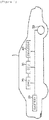
FIG. 1 is a diagram schematically illustrating an electric vehicle, to which an apparatus and a method of balancing voltages between battery racks according to an exemplary embodiment of the present invention are applicable. -
FIG. 2 is a view schematically illustrating an apparatus for balancing voltages between battery racks according to an exemplary embodiment of the present invention. -
FIG. 3 is a diagram schematically illustrating a first battery group sequentially performing voltage balancing from a high voltage in the apparatus and the method of balancing voltages between battery racks according to the exemplary embodiment of the present invention. -
FIG. 4 is a diagram schematically illustrating a second battery group sequentially performing voltage balancing from a lower voltage in the apparatus and the method of balancing voltages between battery racks according to the exemplary embodiment of the present invention. -
FIG. 5 is a diagram schematically illustrating the voltage balancing of the first battery group and the second battery group in the apparatus and the method of balancing voltages between battery racks according to the exemplary embodiment of the present invention. - The present invention will be described below with reference to the accompanying drawings. Herein, repeated descriptions and the detailed description of a publicly known function and configuration that may make the gist of the present invention unnecessarily ambiguous will be omitted. Exemplary embodiments of the present invention are provided so as to more completely explain the present invention to those skilled in the art. Accordingly, the shape, the size, etc., of elements in the figures may be exaggerated for more clear explanation.
- Throughout the specification and the claims, unless explicitly described to the contrary, the word "include/comprise" and variations such as "includes/comprises" or "including/comprising" mean further including other constituent elements, not excluding the other constituent elements.
- In addition, the term "... unit" described in the specification means a unit for processing at least one function and operation and may be implemented by hardware components or software components and combinations thereof.
- An electric vehicle described below refers to a vehicle including one or more electric motors as driving force. Energy used for driving an electric vehicle includes a rechargeable battery and/or an electrical source, such as a fuel cell. The electric vehicle may be a hybrid vehicle using an internal combustion engine as another power source.
-
FIG. 1 is a diagram schematically illustrating an electric vehicle, to which an apparatus and a method of balancing voltages between battery racks according to an exemplary embodiment of the present invention are applicable. - However, the apparatus and the method of balancing voltages between battery racks according to the exemplary embodiment of the present invention may be applicable to various technical fields, such as an energy storage system (ESS) for family use and/or for an industry or an uninterruptible power supply (UPS) system, to which a battery is applied, as well as the electric vehicle.
- The
electric vehicle 1 may include abattery 10, a battery management system (BMS) 20, an electronic control unit (ECU) 30, aninverter 40, and amotor 50. - The
battery 10 is an electric energy source for driving theelectric vehicle 1 by providing driving force to themotor 50. Thebattery 10 may be charged or discharged by theinverter 40 according to the driving of themotor 50 and/or an internal combustion engine (not illustrated). - Here, the kind of
battery 10 is not particularly limited, and examples of thebattery 10 may include a lithium ion battery, a lithium polymer battery, a nickel cadmium battery, a nickel hydrogen battery, a nickel zinc battery, and the like. - Further, the
battery 10 may be formed of a battery pack, in which a plurality of battery cells is connected in series and/or in parallel. Further, one or more battery packs are provided to form thebattery 10. - The
BMS 20 may estimate a state of thebattery 10, and manage thebattery 10 by using information on the estimated state. For example, theBMS 20 may estimate and manage state information about thebattery 10, such as a state of charging (SOC), a state of health (SOH), the amount of maximum input/output allowance power, and an output voltage. Further, theBMS 20 may control charging or discharging of thebattery 10 by using the state information, and further, may also estimate a replacement time of thebattery 10. - Further, the
BMS 20 may include an apparatus 100 (seeFIG. 2 ) for balancing voltages between battery racks, which is to be described below. When a difference in a voltage value between the plurality of battery racks is equal to or larger than a predetermined setting value, theBMS 20 performs voltage balancing between two battery racks among the plurality of battery racks, and repeatedly performs the voltage balancing between the battery racks, on which the voltage balancing is performed, and a battery rack, on which the voltage balancing is not performed, thereby using a whole state of charging (SOC) of thebattery 10. - The ECU 30 is an electronic control device for controlling a state of the
electric vehicle 1. For example, the ECU 30 may determine a torque level based on information about an accelerator, a brake, a speed, and the like, and control an output of themotor 50 so as to correspond to torque information. - Further, the
ECU 30 may transmit a control signal to theinverter 40 so that thebattery 10 is chargeable or dischargeable based on the state information, such as an SOH and an SOC, of thebattery 10 received from theBMS 20. - The
inverter 40 makes thebattery 10 be charged or discharged based on the control signal of theECU 30. - The
motor 50 may drive theelectric vehicle 1 based on control information (for example, the torque information) transmitted from theECU 30 by using electric energy of thebattery 10. - The
electric vehicle 1 is driven by using the electric energy of thebattery 10, so that it is important to use the SOC by balancing the voltages between the battery racks. - Accordingly, hereinafter, the apparatus and the method of balancing voltages between battery racks according to the present invention will be described with reference to
FIGS. 2 to 6 . -
FIG. 2 is a view schematically illustrating theapparatus 100 for balancing voltages between battery racks according to the exemplary embodiment of the present invention. - Referring to
FIG. 2 , theapparatus 100 for balancing voltages between battery racks according to the exemplary embodiment of the present invention may include avoltage measuring unit 110, avoltage collecting unit 120, and acontrol unit 130. - The
apparatus 100 for balancing voltages between battery racks illustrated inFIG. 2 may be connected withbattery racks 11 to N and measure, collect, and control voltages of the battery racks 11 to N. - Here, each of the battery racks 11 to N may include a plurality of battery cells, and the battery cells may be connected in series or in parallel. As a matter of course, the battery racks 11 to N may be provided in plural to form a battery having a higher output or higher capacity.
- The
apparatus 100 for balancing voltages between battery racks illustrated inFIG. 2 is in accordance with the exemplary embodiment, and the constituent elements of theapparatus 100 for balancing voltages between battery racks are not limited to the exemplary embodiment illustrated inFIG. 2 , and some constituent elements may be added, changed, or deleted as necessary. - The
voltage measuring unit 110 measures voltages of the battery racks 11 to N. For example, thevoltage measuring unit 110 may be connected to sensing lines at both ends of the battery racks 11 to N to measure voltages of the battery racks 11 to N. - The
voltage collecting unit 120 may collect the voltages of the plurality ofbattery racks 11 to N measured by thevoltage measuring unit 110. - The
control unit 130 may control the voltage balancing of the battery racks 11 to N to be repeatedly performed based on the voltages of the battery racks 11 to N collected by thevoltage collecting unit 120. This will be described in more detail with reference toFIGS. 3 to 5 . -
FIG. 3 is a diagram schematically illustrating a first battery group sequentially performing the voltage balancing from a high voltage in the apparatus and the method of balancing voltages between battery racks according to the exemplary embodiment of the present invention. - Referring to
FIG. 3 , thecontrol unit 130 selects thebattery rack 11 having the highest voltage and thebattery rack 12 having the second highest voltage from among the battery racks 11 to N, and discharges thebattery rack 11 having the highest voltage and charges thebattery rack 12 having the second highest voltage by using a discharged current, to control the voltage balancing to be performed between thebattery rack 11 having the highest voltage and thebattery rack 12 having the second highest voltage. - Here, the
control unit 130 controls the voltage balancing to be repeatedly performed between the battery racks 11 and 12, on which the voltage balancing is performed, and thebattery rack 13, which has the closest voltage value to the voltages of the battery racks 11 and 12, on which the voltage balancing is performed, among the battery racks, on which the voltage balancing is not performed. - For example, in
FIG. 3 , thecontrol unit 130 controls the voltage balancing to be sequentially and repeatedly performed in such a manner that the voltage balancing is performed between thebattery rack 11 having the highest voltage of 610 V and thebattery rack 12 having the second highest voltage of 600 V, the voltage balancing is performed between the battery racks 11 and 12 and thebattery rack 13, which has the closest voltage value of 590 V to the voltages of the battery racks 11 and 12, on which the voltage balancing is performed, and the voltage balancing is performed between the battery racks 11, 12, and 13 and thebattery rack 14, which has the closest voltage value of 580 V to the voltages of the battery racks 11, 12, and 13, on which the voltage balancing is performed. -
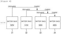
FIG. 4 is a diagram schematically illustrating a second battery group sequentially performing the voltage balancing from a lower voltage in the apparatus and the method of balancing voltages between battery racks according to the exemplary embodiment of the present invention. - Referring to
FIG. 4 , thecontrol unit 130 selects the battery rack N having the lowest voltage and the battery rack N-1 having the second lowest voltage from among the battery racks 11 to N, discharges the battery rack N-1 having the second lowest voltage and charges the battery rack N having the lowest voltage by using a discharged current, to control the voltage balancing to be performed between the battery rack N having the lowest voltage and the battery rack N-1 having the second lowest voltage. - Here, the
control unit 130 controls the voltage balancing to be repeatedly performed between the battery racks N and N-1, on which the voltage balancing is performed, and the battery rack N-2, which has the closest voltage value to the voltages of the battery racks N and N-1, on which the voltage balancing is performed, among the battery racks, on which the voltage balancing is not performed. - For example, in
FIG. 4 , thecontrol unit 130 controls the voltage balancing to be sequentially and repeatedly performed in such a manner that the voltage balancing is performed between thebattery rack 34 having the lowest voltage of 490V and thebattery rack 33 having the second lowest voltage of 500V, the voltage balancing is performed between the battery racks 33 and 34 and thebattery rack 32, which has the closest voltage value of 510V to the voltages of the battery racks 33 and 34, on which the voltage balancing is performed, and the voltage balancing is performed between the battery racks 32, 33, and 34 and thebattery rack 31, which has the closest voltage value of 520V to the voltages of the battery racks 32, 33, and 34, on which the voltage balancing is performed. -
FIG. 5 is a diagram schematically illustrating the voltage balancing of a first battery group A and a second battery group B in the apparatus and the method of balancing voltages between battery racks according to the exemplary embodiment of the present invention. - Here, the
control unit 130 controls the voltage balancing to be performed between the first battery group A and the second battery group B by discharging the first battery group A and charging the second battery group B by using the discharged current. - The
control unit 130 performs the voltage balancing on the first battery group A and the second battery group B and then terminates the voltage balancing between the battery racks. -
FIG. 6 is a flowchart schematically illustrating a method of balancing voltages between battery racks according to an exemplary embodiment of the present invention. - Referring to
FIG. 6 , when the voltage balancing between battery racks according to the exemplary embodiment of the present invention starts, first, a voltage of a plurality of battery racks is measured (S210). For example, a sensing line may be connected to both ends of the battery racks, thereby measuring voltages of the battery racks. - Next, the measured voltage of the plurality of battery racks is collected (S211).
- When a difference in a voltage value between two battery racks among the collected voltage of the plurality of battery racks is equal to or larger than a predetermined setting value, the voltage balancing is controlled to start (S212). Here, when the difference in the voltage value between the battery racks is equal to or less than the predetermined setting value, the operation of determining a difference in a voltage value between the battery racks is controlled to be repeated.
- When the voltage balancing starts, the voltage balancing is controlled to be performed between the battery rack having the highest voltage and the battery rack having the second highest voltage (S213), and the voltage balancing is controlled to be performed between the battery racks, on which the voltage balancing is performed, and the battery rack having the third highest voltage among the plurality of battery racks (S215). As described above, the voltage balancing is controlled to be performed up to the battery rack having the Mth highest voltage among the plurality of battery racks by controlling the voltage balancing to be sequentially performed according to the voltage value of the battery rack (S217).
- Further, similar to the above description, the voltage balancing is controlled to be performed between the battery rack having the lowest voltage and the battery rack having the second lowest voltage (S214), and the voltage balancing is controlled to be performed between the battery racks, on which the voltage balancing is performed, and the battery rack having the third lowest voltage among the plurality of battery racks (S216). Here, the voltage balancing is also controlled to be performed up to the battery rack having the Nth lowest voltage among the plurality of battery racks by controlling the voltage balancing to be sequentially performed according to the voltage value of the battery rack (S218).
- In the exemplary embodiment, the sequential performance of the voltage balancing from the high voltage and the sequential performance of the voltage balancing from the low voltage may be performed at the same time.
- Then, the voltage balancing is also controlled to be performed between a first battery rack group, on which the voltage balancing is sequentially performed from the high voltage and a second battery rack group, on which the voltage balancing is sequentially performed from the low voltage, and the voltage balancing between the battery racks is terminated.
- As described above, when a difference in a voltage value between the plurality of battery racks is equal to or larger than a predetermined setting value, the apparatus and the method of balancing voltages between battery racks perform the voltage balancing between two battery racks among the plurality of battery racks, and repeatedly perform the voltage balancing between the battery racks, on which the voltage balancing is performed, and a battery rack, on which the voltage balancing is not performed, thereby using a whole SOC of the battery, and decreasing costs.
- In the above description, the technical spirit of the present invention is simply illustrative, and those skilled in the art may change and modify the present invention in various ways without departing from the essential characteristic of the present invention. Accordingly, the various exemplary embodiments disclosed herein are not intended to limit but describe the technical spirit of the present invention, and the scope of the technical spirit of the present invention is not limited by the exemplary embodiment. The scope of the present invention should be construed based on the following appended claims and it should be construed that the technical spirit included within the scope equivalent to the claims belongs to the scope of the right of the present invention.
Claims (10)
- An apparatus for balancing voltages between battery racks, the apparatus comprising:a voltage measuring unit configured to measure a voltage of a plurality of battery racks;a collecting unit configured to collect the measured voltage of the plurality of battery racks; anda control unit configured to control voltage balancing to be performed between two battery racks among the plurality of battery racks based on the collected voltage of the plurality of battery racks, and control the voltage balancing to be repeatedly performed between the battery racks, on which the voltage balancing is performed, and the battery rack, on which the voltage balancing is not performed.
- The apparatus of claim 1, wherein the control unit selects a battery rack having the lowest voltage and a battery rack having the second lowest voltage from among the plurality of battery racks, discharges the battery rack having the second lowest voltage and charges the battery rack having the lowest voltage by using a discharged current to control the voltage balancing to be performed between the battery rack having the lowest voltage and the battery rack having the second lowest voltage, and selects a battery rack having the highest voltage and a battery rack having the second highest voltage from among the plurality of battery racks, discharges the battery rack having the highest voltage and charges the battery rack having the second highest voltage by using a discharged current to control the voltage balancing to be performed between the battery rack having the highest voltage and the battery rack having the second highest voltage.
- The apparatus of claim 2, wherein the control unit controls the voltage balancing to be repeatedly performed between the battery racks, on which the voltage balancing is performed, and a battery rack, which has the closest voltage value to the voltages of the battery racks, on which the voltage balancing is performed, among the battery racks, on which the voltage balancing is not performed.
- The apparatus of claim 3, wherein the control unit performs the voltage balancing on all of the plurality of battery racks, and controls the voltage balancing to be performed between a first battery rack group, on which the voltage balancing is sequentially performed from a high voltage and a second battery rack group, on which the voltage balancing is sequentially performed from a low voltage.
- The apparatus of claim 1, wherein when a difference in a voltage value between two battery racks among the plurality of battery racks is equal to or larger than a predetermined setting value, the control unit controls the voltage balancing to start.
- A method of balancing voltages between battery racks, the method comprising:measuring a voltage of a plurality of battery racks;collecting the measured voltage of the plurality of battery racks; andcontrolling voltage balancing to be performed between two battery racks among the plurality of battery racks based on the collected voltage of the plurality of battery racks, and controlling the voltage balancing to be repeatedly performed between the battery racks, on which the voltage balancing is performed, and the battery rack, on which the voltage balancing is not performed.
- The method of claim 6, wherein the controlling of the voltage balancing to be repeatedly performed includes:selecting a battery rack having the lowest voltage and a battery rack having the second lowest voltage from among the plurality of battery racks, discharging the battery rack having the second lowest voltage and charging the battery rack having the lowest voltage by using a discharged current to control the voltage balancing to be performed between the battery rack having the lowest voltage and the battery rack having the second lowest voltage; andselecting a battery rack having the highest voltage and a battery rack having the second highest voltage from among the plurality of battery racks, discharging the battery rack having the highest voltage and charging the battery rack having the second highest voltage by using a discharged current to control the voltage balancing to be performed between the battery rack having the highest voltage and the battery rack having the second highest voltage.
- The method of claim 7, wherein the controlling of the voltage balancing to be repeatedly performed further includes controlling the voltage balancing to be repeatedly performed between the battery racks, on which the voltage balancing is performed, and a battery rack, which has the closest voltage value to the voltages of the battery racks, on which the voltage balancing is performed, among the battery racks, on which the voltage balancing is not performed.
- The method of claim 8, wherein the controlling of the voltage balancing to be repeatedly performed further includes performing the voltage balancing on all of the plurality of battery racks, and performing the voltage balancing between a first battery rack group, on which the voltage balancing is sequentially performed from a high voltage and a second battery rack group, on which the voltage balancing is sequentially performed from a low voltage.
- The method of claim 6, wherein the controlling of the voltage balancing to be repeatedly performed further includes, when a difference in a voltage value between two battery racks among the plurality of battery racks is equal to or larger than a predetermined setting value, controlling the voltage balancing to start.
Applications Claiming Priority (1)
| Application Number | Priority Date | Filing Date | Title |
|---|---|---|---|
| PCT/KR2015/014211 WO2017111187A1 (en) | 2015-12-23 | 2015-12-23 | Apparatus and method for voltage balancing between battery racks |
Publications (3)
| Publication Number | Publication Date |
|---|---|
| EP3223387A1 true EP3223387A1 (en) | 2017-09-27 |
| EP3223387A4 EP3223387A4 (en) | 2018-06-27 |
| EP3223387B1 EP3223387B1 (en) | 2019-04-03 |
Family
ID=59090565
Family Applications (1)
| Application Number | Title | Priority Date | Filing Date |
|---|---|---|---|
| EP15907564.7A Active EP3223387B1 (en) | 2015-12-23 | 2015-12-23 | Apparatus and method for voltage balancing between battery racks |
Country Status (5)
| Country | Link |
|---|---|
| US (1) | US10181733B2 (en) |
| EP (1) | EP3223387B1 (en) |
| JP (1) | JP6492175B2 (en) |
| CN (1) | CN107210609B (en) |
| WO (1) | WO2017111187A1 (en) |
Families Citing this family (5)
| Publication number | Priority date | Publication date | Assignee | Title |
|---|---|---|---|---|
| JP7035891B2 (en) * | 2018-08-03 | 2022-03-15 | 株式会社Gsユアサ | Inspection equipment, inspection method |
| EP4044396A1 (en) * | 2021-02-12 | 2022-08-17 | STABL Energy GmbH | Failsafe battery storage system |
| CN113370840B (en) * | 2021-06-23 | 2022-07-01 | 深圳市誉娇诚科技有限公司 | Charging control algorithm adaptive to different low-speed electric vehicle voltage levels |
| CN114407715B (en) * | 2022-01-20 | 2023-06-30 | 株洲中车特种装备科技有限公司 | Charging method for energy storage system of railway vehicle |
| WO2023215526A1 (en) * | 2022-05-06 | 2023-11-09 | Zero Nox, Inc. | Modularization and power management of battery modules |
Family Cites Families (23)
| Publication number | Priority date | Publication date | Assignee | Title |
|---|---|---|---|---|
| JP2000166113A (en) * | 1998-11-27 | 2000-06-16 | Enakkusu Kk | Method and device for balancing lithium ion battery pack |
| JP2007020368A (en) * | 2005-07-11 | 2007-01-25 | Komatsu Ltd | Voltage equalizer of accumulation element, and method therefor |
| CN101017986B (en) * | 2006-12-29 | 2010-05-19 | 哈尔滨工业大学 | Balancer in the charging/discharging process of the dynamic battery group |
| JP4587233B2 (en) * | 2007-10-23 | 2010-11-24 | 本田技研工業株式会社 | Discharge control device |
| KR100966732B1 (en) | 2008-02-28 | 2010-06-29 | 쌍용자동차 주식회사 | Battery Equalizing-charge Device of Battery System and Method thereof |
| JP2010093980A (en) * | 2008-10-09 | 2010-04-22 | Daimler Ag | Power supply for vehicle |
| CN102035010B (en) | 2009-09-29 | 2013-05-01 | 凹凸电子(武汉)有限公司 | Battery unit equalizing circuit and method |
| JP5440315B2 (en) * | 2010-03-26 | 2014-03-12 | 株式会社Ihi | Battery module and module voltage balancing method using the battery module |
| WO2012049963A1 (en) * | 2010-10-15 | 2012-04-19 | 三洋電機株式会社 | Power system comprising storage batteries |
| WO2013008859A1 (en) * | 2011-07-12 | 2013-01-17 | 三洋電機株式会社 | Battery assembly control system |
| KR101243493B1 (en) * | 2011-09-02 | 2013-03-13 | 삼성에스디아이 주식회사 | Control system of battery pack and method of chaeging and discharge using the same |
| JP5918961B2 (en) | 2011-10-07 | 2016-05-18 | 株式会社ケーヒン | Cell balance control device |
| JP5126403B1 (en) * | 2011-10-31 | 2013-01-23 | 株式会社豊田自動織機 | Charge / discharge control device |
| JP5987512B2 (en) | 2012-07-10 | 2016-09-07 | 三菱自動車工業株式会社 | Vehicle battery control device |
| EP2696465B1 (en) * | 2012-08-09 | 2016-12-21 | Samsung SDI Co., Ltd. | Battery management system and cell balancing method |
| JP2014093925A (en) * | 2012-11-07 | 2014-05-19 | Toyota Industries Corp | Voltage equalization device |
| JP2014147167A (en) * | 2013-01-28 | 2014-08-14 | Toyota Industries Corp | Cell balance control device and cell balance control method |
| CN105210258B (en) * | 2013-03-15 | 2019-04-23 | 设计通量技术公司 | For generate can dynamic recognition energy storage device method and apparatus |
| KR20140122520A (en) * | 2013-04-10 | 2014-10-20 | 주식회사 레보 | Apparatus and Method for balancing using voltage difference |
| KR101494081B1 (en) * | 2013-05-31 | 2015-02-16 | 국립대학법인 울산과학기술대학교 산학협력단 | Apparatus for balancing of battery voltage using fuzzy algorism |
| KR101592200B1 (en) * | 2013-08-28 | 2016-02-05 | 주식회사 엘지화학 | Method of Rack Voltage Balancing for Battery Pack Having Rack |
| CN203562806U (en) * | 2013-11-12 | 2014-04-23 | 安徽安凯汽车股份有限公司 | Electric-automobile low-voltage battery charging system |
| KR101632694B1 (en) | 2014-01-28 | 2016-06-22 | 주식회사 엘지화학 | Battery cell voltage balancing apparatus and method |
-
2015
- 2015-12-23 JP JP2017525572A patent/JP6492175B2/en active Active
- 2015-12-23 WO PCT/KR2015/014211 patent/WO2017111187A1/en active Application Filing
- 2015-12-23 US US15/522,122 patent/US10181733B2/en active Active
- 2015-12-23 EP EP15907564.7A patent/EP3223387B1/en active Active
- 2015-12-23 CN CN201580061406.3A patent/CN107210609B/en active Active
Also Published As
| Publication number | Publication date |
|---|---|
| JP6492175B2 (en) | 2019-03-27 |
| WO2017111187A1 (en) | 2017-06-29 |
| EP3223387A4 (en) | 2018-06-27 |
| EP3223387B1 (en) | 2019-04-03 |
| CN107210609B (en) | 2020-02-28 |
| JP2018516034A (en) | 2018-06-14 |
| US20170373511A1 (en) | 2017-12-28 |
| CN107210609A (en) | 2017-09-26 |
| US10181733B2 (en) | 2019-01-15 |
Similar Documents
| Publication | Publication Date | Title |
|---|---|---|
| EP3223387B1 (en) | Apparatus and method for voltage balancing between battery racks | |
| EP2930811B1 (en) | Apparatus, system and method for preventing damage to battery rack by means of voltage measurement | |
| EP2762907B1 (en) | Apparatus and method for estimating state of charge of battery | |
| EP2033003B1 (en) | Determination of battery predictive power limits | |
| EP2874271B1 (en) | Apparatus and method for controlling battery | |
| WO2013115585A1 (en) | Method and device for predicting state-of-health of battery, and battery management system using same | |
| EP2869074B1 (en) | Device and method for calculating pre-charge resistance of battery pack | |
| EP2587621A1 (en) | Power storage unit control circuit and power storage apparatus | |
| WO2012140776A1 (en) | Charging control device | |
| US10071648B1 (en) | Avoidance of electrode plating in a battery cell | |
| EP3274210B1 (en) | Auxiliary battery charging apparatus and method | |
| KR20130083220A (en) | Apparatus and method of estimating state of charging for battery, and battery management system using the same | |
| KR101572178B1 (en) | Voltage balancing apparatus and method of secondary battery cells | |
| KR101741303B1 (en) | Voltage balancing apparatus and method between battery racks | |
| WO2011114349A2 (en) | Hybrid battery pack | |
| KR101498764B1 (en) | Method and apparatus for battery resistance estimation, and battery management system using the same | |
| Qi et al. | A control strategy for dynamic balancing of lithium iron phosphate battery based on the performance of cell voltage | |
| KR101602530B1 (en) | Battery pack leak diagnosis method and apparatus | |
| US20160190801A1 (en) | Scalable energy storage system | |
| Sivakumar et al. | An investigation on influence of battery materials for efficient lithium-ion battery pack design | |
| KR20150051494A (en) | Battery system for rapid charging | |
| GB2481670A (en) | A battery management system for an electric vehicle | |
| Wager et al. | vehicles under fast-DC charging. International Journal of Electric and Hybrid Vehicles, 8 (4). p. 351. |
Legal Events
| Date | Code | Title | Description |
|---|---|---|---|
| STAA | Information on the status of an ep patent application or granted ep patent |
Free format text: STATUS: UNKNOWN |
|
| STAA | Information on the status of an ep patent application or granted ep patent |
Free format text: STATUS: THE INTERNATIONAL PUBLICATION HAS BEEN MADE |
|
| PUAI | Public reference made under article 153(3) epc to a published international application that has entered the european phase |
Free format text: ORIGINAL CODE: 0009012 |
|
| STAA | Information on the status of an ep patent application or granted ep patent |
Free format text: STATUS: REQUEST FOR EXAMINATION WAS MADE |
|
| 17P | Request for examination filed |
Effective date: 20170512 |
|
| AK | Designated contracting states |
Kind code of ref document: A1 Designated state(s): AL AT BE BG CH CY CZ DE DK EE ES FI FR GB GR HR HU IE IS IT LI LT LU LV MC MK MT NL NO PL PT RO RS SE SI SK SM TR |
|
| AX | Request for extension of the european patent |
Extension state: BA ME |
|
| RIN1 | Information on inventor provided before grant (corrected) |
Inventor name: JO, YONGMIN |
|
| A4 | Supplementary search report drawn up and despatched |
Effective date: 20180530 |
|
| RIC1 | Information provided on ipc code assigned before grant |
Ipc: H02J 7/00 20060101AFI20180524BHEP Ipc: G01R 31/36 20060101ALI20180524BHEP Ipc: H01M 10/44 20060101ALI20180524BHEP Ipc: B60L 11/18 20060101ALI20180524BHEP |
|
| GRAP | Despatch of communication of intention to grant a patent |
Free format text: ORIGINAL CODE: EPIDOSNIGR1 |
|
| STAA | Information on the status of an ep patent application or granted ep patent |
Free format text: STATUS: GRANT OF PATENT IS INTENDED |
|
| DAX | Request for extension of the european patent (deleted) | ||
| INTG | Intention to grant announced |
Effective date: 20181205 |
|
| GRAS | Grant fee paid |
Free format text: ORIGINAL CODE: EPIDOSNIGR3 |
|
| GRAA | (expected) grant |
Free format text: ORIGINAL CODE: 0009210 |
|
| STAA | Information on the status of an ep patent application or granted ep patent |
Free format text: STATUS: THE PATENT HAS BEEN GRANTED |
|
| AK | Designated contracting states |
Kind code of ref document: B1 Designated state(s): AL AT BE BG CH CY CZ DE DK EE ES FI FR GB GR HR HU IE IS IT LI LT LU LV MC MK MT NL NO PL PT RO RS SE SI SK SM TR |
|
| DAV | Request for validation of the european patent (deleted) | ||
| REG | Reference to a national code |
Ref country code: GB Ref legal event code: FG4D |
|
| REG | Reference to a national code |
Ref country code: CH Ref legal event code: EP Ref country code: AT Ref legal event code: REF Ref document number: 1116943 Country of ref document: AT Kind code of ref document: T Effective date: 20190415 |
|
| REG | Reference to a national code |
Ref country code: DE Ref legal event code: R096 Ref document number: 602015027844 Country of ref document: DE |
|
| REG | Reference to a national code |
Ref country code: IE Ref legal event code: FG4D |
|
| REG | Reference to a national code |
Ref country code: NL Ref legal event code: MP Effective date: 20190403 |
|
| REG | Reference to a national code |
Ref country code: LT Ref legal event code: MG4D |
|
| REG | Reference to a national code |
Ref country code: AT Ref legal event code: MK05 Ref document number: 1116943 Country of ref document: AT Kind code of ref document: T Effective date: 20190403 |
|
| PG25 | Lapsed in a contracting state [announced via postgrant information from national office to epo] |
Ref country code: NL Free format text: LAPSE BECAUSE OF FAILURE TO SUBMIT A TRANSLATION OF THE DESCRIPTION OR TO PAY THE FEE WITHIN THE PRESCRIBED TIME-LIMIT Effective date: 20190403 |
|
| PG25 | Lapsed in a contracting state [announced via postgrant information from national office to epo] |
Ref country code: ES Free format text: LAPSE BECAUSE OF FAILURE TO SUBMIT A TRANSLATION OF THE DESCRIPTION OR TO PAY THE FEE WITHIN THE PRESCRIBED TIME-LIMIT Effective date: 20190403 Ref country code: PT Free format text: LAPSE BECAUSE OF FAILURE TO SUBMIT A TRANSLATION OF THE DESCRIPTION OR TO PAY THE FEE WITHIN THE PRESCRIBED TIME-LIMIT Effective date: 20190803 Ref country code: SE Free format text: LAPSE BECAUSE OF FAILURE TO SUBMIT A TRANSLATION OF THE DESCRIPTION OR TO PAY THE FEE WITHIN THE PRESCRIBED TIME-LIMIT Effective date: 20190403 Ref country code: AL Free format text: LAPSE BECAUSE OF FAILURE TO SUBMIT A TRANSLATION OF THE DESCRIPTION OR TO PAY THE FEE WITHIN THE PRESCRIBED TIME-LIMIT Effective date: 20190403 Ref country code: FI Free format text: LAPSE BECAUSE OF FAILURE TO SUBMIT A TRANSLATION OF THE DESCRIPTION OR TO PAY THE FEE WITHIN THE PRESCRIBED TIME-LIMIT Effective date: 20190403 Ref country code: NO Free format text: LAPSE BECAUSE OF FAILURE TO SUBMIT A TRANSLATION OF THE DESCRIPTION OR TO PAY THE FEE WITHIN THE PRESCRIBED TIME-LIMIT Effective date: 20190703 Ref country code: LT Free format text: LAPSE BECAUSE OF FAILURE TO SUBMIT A TRANSLATION OF THE DESCRIPTION OR TO PAY THE FEE WITHIN THE PRESCRIBED TIME-LIMIT Effective date: 20190403 Ref country code: CZ Free format text: LAPSE BECAUSE OF FAILURE TO SUBMIT A TRANSLATION OF THE DESCRIPTION OR TO PAY THE FEE WITHIN THE PRESCRIBED TIME-LIMIT Effective date: 20190403 Ref country code: HR Free format text: LAPSE BECAUSE OF FAILURE TO SUBMIT A TRANSLATION OF THE DESCRIPTION OR TO PAY THE FEE WITHIN THE PRESCRIBED TIME-LIMIT Effective date: 20190403 |
|
| PG25 | Lapsed in a contracting state [announced via postgrant information from national office to epo] |
Ref country code: RS Free format text: LAPSE BECAUSE OF FAILURE TO SUBMIT A TRANSLATION OF THE DESCRIPTION OR TO PAY THE FEE WITHIN THE PRESCRIBED TIME-LIMIT Effective date: 20190403 Ref country code: PL Free format text: LAPSE BECAUSE OF FAILURE TO SUBMIT A TRANSLATION OF THE DESCRIPTION OR TO PAY THE FEE WITHIN THE PRESCRIBED TIME-LIMIT Effective date: 20190403 Ref country code: GR Free format text: LAPSE BECAUSE OF FAILURE TO SUBMIT A TRANSLATION OF THE DESCRIPTION OR TO PAY THE FEE WITHIN THE PRESCRIBED TIME-LIMIT Effective date: 20190704 Ref country code: BG Free format text: LAPSE BECAUSE OF FAILURE TO SUBMIT A TRANSLATION OF THE DESCRIPTION OR TO PAY THE FEE WITHIN THE PRESCRIBED TIME-LIMIT Effective date: 20190703 Ref country code: LV Free format text: LAPSE BECAUSE OF FAILURE TO SUBMIT A TRANSLATION OF THE DESCRIPTION OR TO PAY THE FEE WITHIN THE PRESCRIBED TIME-LIMIT Effective date: 20190403 |
|
| PG25 | Lapsed in a contracting state [announced via postgrant information from national office to epo] |
Ref country code: IS Free format text: LAPSE BECAUSE OF FAILURE TO SUBMIT A TRANSLATION OF THE DESCRIPTION OR TO PAY THE FEE WITHIN THE PRESCRIBED TIME-LIMIT Effective date: 20190803 Ref country code: AT Free format text: LAPSE BECAUSE OF FAILURE TO SUBMIT A TRANSLATION OF THE DESCRIPTION OR TO PAY THE FEE WITHIN THE PRESCRIBED TIME-LIMIT Effective date: 20190403 |
|
| REG | Reference to a national code |
Ref country code: DE Ref legal event code: R097 Ref document number: 602015027844 Country of ref document: DE |
|
| PG25 | Lapsed in a contracting state [announced via postgrant information from national office to epo] |
Ref country code: DK Free format text: LAPSE BECAUSE OF FAILURE TO SUBMIT A TRANSLATION OF THE DESCRIPTION OR TO PAY THE FEE WITHIN THE PRESCRIBED TIME-LIMIT Effective date: 20190403 Ref country code: EE Free format text: LAPSE BECAUSE OF FAILURE TO SUBMIT A TRANSLATION OF THE DESCRIPTION OR TO PAY THE FEE WITHIN THE PRESCRIBED TIME-LIMIT Effective date: 20190403 Ref country code: RO Free format text: LAPSE BECAUSE OF FAILURE TO SUBMIT A TRANSLATION OF THE DESCRIPTION OR TO PAY THE FEE WITHIN THE PRESCRIBED TIME-LIMIT Effective date: 20190403 Ref country code: SK Free format text: LAPSE BECAUSE OF FAILURE TO SUBMIT A TRANSLATION OF THE DESCRIPTION OR TO PAY THE FEE WITHIN THE PRESCRIBED TIME-LIMIT Effective date: 20190403 |
|
| PLBE | No opposition filed within time limit |
Free format text: ORIGINAL CODE: 0009261 |
|
| STAA | Information on the status of an ep patent application or granted ep patent |
Free format text: STATUS: NO OPPOSITION FILED WITHIN TIME LIMIT |
|
| PG25 | Lapsed in a contracting state [announced via postgrant information from national office to epo] |
Ref country code: IT Free format text: LAPSE BECAUSE OF FAILURE TO SUBMIT A TRANSLATION OF THE DESCRIPTION OR TO PAY THE FEE WITHIN THE PRESCRIBED TIME-LIMIT Effective date: 20190403 Ref country code: SM Free format text: LAPSE BECAUSE OF FAILURE TO SUBMIT A TRANSLATION OF THE DESCRIPTION OR TO PAY THE FEE WITHIN THE PRESCRIBED TIME-LIMIT Effective date: 20190403 |
|
| 26N | No opposition filed |
Effective date: 20200106 |
|
| PG25 | Lapsed in a contracting state [announced via postgrant information from national office to epo] |
Ref country code: TR Free format text: LAPSE BECAUSE OF FAILURE TO SUBMIT A TRANSLATION OF THE DESCRIPTION OR TO PAY THE FEE WITHIN THE PRESCRIBED TIME-LIMIT Effective date: 20190403 |
|
| PG25 | Lapsed in a contracting state [announced via postgrant information from national office to epo] |
Ref country code: SI Free format text: LAPSE BECAUSE OF FAILURE TO SUBMIT A TRANSLATION OF THE DESCRIPTION OR TO PAY THE FEE WITHIN THE PRESCRIBED TIME-LIMIT Effective date: 20190403 |
|
| REG | Reference to a national code |
Ref country code: CH Ref legal event code: PL |
|
| REG | Reference to a national code |
Ref country code: BE Ref legal event code: MM Effective date: 20191231 |
|
| PG25 | Lapsed in a contracting state [announced via postgrant information from national office to epo] |
Ref country code: MC Free format text: LAPSE BECAUSE OF FAILURE TO SUBMIT A TRANSLATION OF THE DESCRIPTION OR TO PAY THE FEE WITHIN THE PRESCRIBED TIME-LIMIT Effective date: 20190403 |
|
| PG25 | Lapsed in a contracting state [announced via postgrant information from national office to epo] |
Ref country code: LU Free format text: LAPSE BECAUSE OF NON-PAYMENT OF DUE FEES Effective date: 20191223 Ref country code: IE Free format text: LAPSE BECAUSE OF NON-PAYMENT OF DUE FEES Effective date: 20191223 |
|
| PG25 | Lapsed in a contracting state [announced via postgrant information from national office to epo] |
Ref country code: CH Free format text: LAPSE BECAUSE OF NON-PAYMENT OF DUE FEES Effective date: 20191231 Ref country code: LI Free format text: LAPSE BECAUSE OF NON-PAYMENT OF DUE FEES Effective date: 20191231 Ref country code: BE Free format text: LAPSE BECAUSE OF NON-PAYMENT OF DUE FEES Effective date: 20191231 |
|
| PG25 | Lapsed in a contracting state [announced via postgrant information from national office to epo] |
Ref country code: CY Free format text: LAPSE BECAUSE OF FAILURE TO SUBMIT A TRANSLATION OF THE DESCRIPTION OR TO PAY THE FEE WITHIN THE PRESCRIBED TIME-LIMIT Effective date: 20190403 |
|
| PG25 | Lapsed in a contracting state [announced via postgrant information from national office to epo] |
Ref country code: HU Free format text: LAPSE BECAUSE OF FAILURE TO SUBMIT A TRANSLATION OF THE DESCRIPTION OR TO PAY THE FEE WITHIN THE PRESCRIBED TIME-LIMIT; INVALID AB INITIO Effective date: 20151223 Ref country code: MT Free format text: LAPSE BECAUSE OF FAILURE TO SUBMIT A TRANSLATION OF THE DESCRIPTION OR TO PAY THE FEE WITHIN THE PRESCRIBED TIME-LIMIT Effective date: 20190403 |
|
| PG25 | Lapsed in a contracting state [announced via postgrant information from national office to epo] |
Ref country code: MK Free format text: LAPSE BECAUSE OF FAILURE TO SUBMIT A TRANSLATION OF THE DESCRIPTION OR TO PAY THE FEE WITHIN THE PRESCRIBED TIME-LIMIT Effective date: 20190403 |
|
| P01 | Opt-out of the competence of the unified patent court (upc) registered |
Effective date: 20230512 |
|
| REG | Reference to a national code |
Ref country code: DE Ref legal event code: R081 Ref document number: 602015027844 Country of ref document: DE Owner name: LG ENERGY SOLUTION, LTD., KR Free format text: FORMER OWNER: LG CHEM, LTD., SEOUL, KR |
|
| REG | Reference to a national code |
Ref country code: GB Ref legal event code: 732E Free format text: REGISTERED BETWEEN 20230824 AND 20230831 |
|
| PGFP | Annual fee paid to national office [announced via postgrant information from national office to epo] |
Ref country code: GB Payment date: 20231120 Year of fee payment: 9 |
|
| PGFP | Annual fee paid to national office [announced via postgrant information from national office to epo] |
Ref country code: FR Payment date: 20231121 Year of fee payment: 9 Ref country code: DE Payment date: 20231120 Year of fee payment: 9 |