EP3223371A2 - Power-electric contact device; exchangeable power-electric contact module as well as power-electric connector - Google Patents
Power-electric contact device; exchangeable power-electric contact module as well as power-electric connector Download PDFInfo
- Publication number
- EP3223371A2 EP3223371A2 EP17162288.9A EP17162288A EP3223371A2 EP 3223371 A2 EP3223371 A2 EP 3223371A2 EP 17162288 A EP17162288 A EP 17162288A EP 3223371 A2 EP3223371 A2 EP 3223371A2
- Authority
- EP
- European Patent Office
- Prior art keywords
- contact
- power
- electric
- connector
- section
- Prior art date
- Legal status (The legal status is an assumption and is not a legal conclusion. Google has not performed a legal analysis and makes no representation as to the accuracy of the status listed.)
- Granted
Links
Images
Classifications
-
- H—ELECTRICITY
- H01—ELECTRIC ELEMENTS
- H01R—ELECTRICALLY-CONDUCTIVE CONNECTIONS; STRUCTURAL ASSOCIATIONS OF A PLURALITY OF MUTUALLY-INSULATED ELECTRICAL CONNECTING ELEMENTS; COUPLING DEVICES; CURRENT COLLECTORS
- H01R13/00—Details of coupling devices of the kinds covered by groups H01R12/70 or H01R24/00 - H01R33/00
- H01R13/02—Contact members
- H01R13/20—Pins, blades, or sockets shaped, or provided with separate member, to retain co-operating parts together
-
- H—ELECTRICITY
- H01—ELECTRIC ELEMENTS
- H01R—ELECTRICALLY-CONDUCTIVE CONNECTIONS; STRUCTURAL ASSOCIATIONS OF A PLURALITY OF MUTUALLY-INSULATED ELECTRICAL CONNECTING ELEMENTS; COUPLING DEVICES; CURRENT COLLECTORS
- H01R13/00—Details of coupling devices of the kinds covered by groups H01R12/70 or H01R24/00 - H01R33/00
- H01R13/46—Bases; Cases
- H01R13/502—Bases; Cases composed of different pieces
- H01R13/506—Bases; Cases composed of different pieces assembled by snap action of the parts
-
- H—ELECTRICITY
- H01—ELECTRIC ELEMENTS
- H01R—ELECTRICALLY-CONDUCTIVE CONNECTIONS; STRUCTURAL ASSOCIATIONS OF A PLURALITY OF MUTUALLY-INSULATED ELECTRICAL CONNECTING ELEMENTS; COUPLING DEVICES; CURRENT COLLECTORS
- H01R13/00—Details of coupling devices of the kinds covered by groups H01R12/70 or H01R24/00 - H01R33/00
- H01R13/02—Contact members
- H01R13/10—Sockets for co-operation with pins or blades
- H01R13/11—Resilient sockets
- H01R13/111—Resilient sockets co-operating with pins having a circular transverse section
-
- H—ELECTRICITY
- H01—ELECTRIC ELEMENTS
- H01R—ELECTRICALLY-CONDUCTIVE CONNECTIONS; STRUCTURAL ASSOCIATIONS OF A PLURALITY OF MUTUALLY-INSULATED ELECTRICAL CONNECTING ELEMENTS; COUPLING DEVICES; CURRENT COLLECTORS
- H01R13/00—Details of coupling devices of the kinds covered by groups H01R12/70 or H01R24/00 - H01R33/00
- H01R13/40—Securing contact members in or to a base or case; Insulating of contact members
- H01R13/42—Securing in a demountable manner
- H01R13/428—Securing in a demountable manner by resilient locking means on the contact members; by locking means on resilient contact members
- H01R13/434—Securing in a demountable manner by resilient locking means on the contact members; by locking means on resilient contact members by separate resilient locking means on contact member, e.g. retainer collar or ring around contact member
-
- H—ELECTRICITY
- H01—ELECTRIC ELEMENTS
- H01R—ELECTRICALLY-CONDUCTIVE CONNECTIONS; STRUCTURAL ASSOCIATIONS OF A PLURALITY OF MUTUALLY-INSULATED ELECTRICAL CONNECTING ELEMENTS; COUPLING DEVICES; CURRENT COLLECTORS
- H01R13/00—Details of coupling devices of the kinds covered by groups H01R12/70 or H01R24/00 - H01R33/00
- H01R13/62—Means for facilitating engagement or disengagement of coupling parts or for holding them in engagement
- H01R13/627—Snap or like fastening
-
- H—ELECTRICITY
- H01—ELECTRIC ELEMENTS
- H01R—ELECTRICALLY-CONDUCTIVE CONNECTIONS; STRUCTURAL ASSOCIATIONS OF A PLURALITY OF MUTUALLY-INSULATED ELECTRICAL CONNECTING ELEMENTS; COUPLING DEVICES; CURRENT COLLECTORS
- H01R24/00—Two-part coupling devices, or either of their cooperating parts, characterised by their overall structure
- H01R24/38—Two-part coupling devices, or either of their cooperating parts, characterised by their overall structure having concentrically or coaxially arranged contacts
-
- H—ELECTRICITY
- H01—ELECTRIC ELEMENTS
- H01R—ELECTRICALLY-CONDUCTIVE CONNECTIONS; STRUCTURAL ASSOCIATIONS OF A PLURALITY OF MUTUALLY-INSULATED ELECTRICAL CONNECTING ELEMENTS; COUPLING DEVICES; CURRENT COLLECTORS
- H01R31/00—Coupling parts supported only by co-operation with counterpart
- H01R31/06—Intermediate parts for linking two coupling parts, e.g. adapter
-
- H—ELECTRICITY
- H01—ELECTRIC ELEMENTS
- H01R—ELECTRICALLY-CONDUCTIVE CONNECTIONS; STRUCTURAL ASSOCIATIONS OF A PLURALITY OF MUTUALLY-INSULATED ELECTRICAL CONNECTING ELEMENTS; COUPLING DEVICES; CURRENT COLLECTORS
- H01R11/00—Individual connecting elements providing two or more spaced connecting locations for conductive members which are, or may be, thereby interconnected, e.g. end pieces for wires or cables supported by the wire or cable and having means for facilitating electrical connection to some other wire, terminal, or conductive member, blocks of binding posts
- H01R11/11—End pieces or tapping pieces for wires, supported by the wire and for facilitating electrical connection to some other wire, terminal or conductive member
- H01R11/26—End pieces terminating in a screw clamp, screw or nut
-
- H—ELECTRICITY
- H01—ELECTRIC ELEMENTS
- H01R—ELECTRICALLY-CONDUCTIVE CONNECTIONS; STRUCTURAL ASSOCIATIONS OF A PLURALITY OF MUTUALLY-INSULATED ELECTRICAL CONNECTING ELEMENTS; COUPLING DEVICES; CURRENT COLLECTORS
- H01R13/00—Details of coupling devices of the kinds covered by groups H01R12/70 or H01R24/00 - H01R33/00
- H01R13/46—Bases; Cases
- H01R13/53—Bases or cases for heavy duty; Bases or cases for high voltage with means for preventing corona or arcing
-
- H—ELECTRICITY
- H01—ELECTRIC ELEMENTS
- H01R—ELECTRICALLY-CONDUCTIVE CONNECTIONS; STRUCTURAL ASSOCIATIONS OF A PLURALITY OF MUTUALLY-INSULATED ELECTRICAL CONNECTING ELEMENTS; COUPLING DEVICES; CURRENT COLLECTORS
- H01R2105/00—Three poles
-
- H—ELECTRICITY
- H01—ELECTRIC ELEMENTS
- H01R—ELECTRICALLY-CONDUCTIVE CONNECTIONS; STRUCTURAL ASSOCIATIONS OF A PLURALITY OF MUTUALLY-INSULATED ELECTRICAL CONNECTING ELEMENTS; COUPLING DEVICES; CURRENT COLLECTORS
- H01R24/00—Two-part coupling devices, or either of their cooperating parts, characterised by their overall structure
- H01R24/86—Parallel contacts arranged about a common axis
-
- H—ELECTRICITY
- H01—ELECTRIC ELEMENTS
- H01R—ELECTRICALLY-CONDUCTIVE CONNECTIONS; STRUCTURAL ASSOCIATIONS OF A PLURALITY OF MUTUALLY-INSULATED ELECTRICAL CONNECTING ELEMENTS; COUPLING DEVICES; CURRENT COLLECTORS
- H01R4/00—Electrically-conductive connections between two or more conductive members in direct contact, i.e. touching one another; Means for effecting or maintaining such contact; Electrically-conductive connections having two or more spaced connecting locations for conductors and using contact members penetrating insulation
- H01R4/56—Electrically-conductive connections between two or more conductive members in direct contact, i.e. touching one another; Means for effecting or maintaining such contact; Electrically-conductive connections having two or more spaced connecting locations for conductors and using contact members penetrating insulation one conductor screwing into another
Definitions
- the invention relates to a power-electric contact device, in particular an electric high-current contact device or an electro-power contact device, for a power-electric connector.
- the invention further relates to an exchangeable power-electric contact module, in particular an exchangeable electric high-current contact module or an exchangeable electro-power contact module, for a power-electric connector.
- the invention furthermore relates to a power-electric connector or a power-electric mating connector, in particular an electric high-current connector or an electro-power connector, e.g. for the three-phase current sector or the electric vehicle sector.
- connectors of this kind have to ensure transmission of current, voltage and/or signals in warm, possibly hot, contaminated, humid and/or chemically aggressive environments permanently, repeatedly and/or after a comparatively long service life, possibly at short notice.
- Connectors of this kind or the housings of connectors of this kind can be installed on an electrical cable, a line etc. and/or an electric device or apparatus, e.g. on/in a housing of a (power-) electric component or a device, assembly etc. of this kind; in the latter case, the connector is often referred to as a (mating) connector device.
- a connector is located only on a cable etc.
- the said connector is usually referred to as a (flying) (plug) connector or a plug (usually with pin contact devices) or a coupling (usually with socket contact devices);
- a (power-) electric component it is usually referred to as a (built-in) connector, such as a (built-in) plug or a (built-in) socket.
- Power-electric connectors have to ensure problem-free transmission of electric power, wherein connectors (connectors and mating connectors) which correspond to one another usually have fastening or locking devices for permanently, but generally releasably, fastening or locking the connector to/in the mating connector. Further, corresponding power-electric contact devices, e.g. a socket contact device, a pin contact device, a tab contact device etc., have to be securely accommodated in the said connector. Efforts are continuously being made to improve power-electric connectors and/or to make the said power-electric connectors more cost-effective.
- charging connectors for electric vehicles require power-electric contact devices which have to transport an electric current (power contact device, grounding contact device) of approximately 32 A at outside temperatures of approximately -30°C to approximately +50°C and at a peak electric voltage of approximately 500 V.
- Signal contact devices have a current of approximately 2 A at a voltage of 30 V.
- the service life of charging connectors of this kind should be approximately or at least 10 to 15 years, wherein, depending on the environment (moisture, sand, salt etc.), it should be possible to carry out 10,000 to 20,000 plug connection cycles with a charging connector of this kind, wherein it is preferred when permanently low contact resistances are also realized. In order to realize such numbers of plug connection cycles with comparatively low contact resistances, the contact devices have to be coated, this again adding to the cost of the contact devices.
- An object of the invention is to specify an improved power-electric connector or an improved power-electric mating connector, in particular an electric high-current connector or an electro-power connector, for example for the three-phase current sector or the electric vehicle sector.
- the connector should be designed for 10,000 to 20,000 plug connection cycles depending on an environment in which the connector is used, wherein the contact devices of the said connector should be comparatively cost-effective. In particular, it should be possible to dispense with comparatively costly coating of the contact devices in this case.
- the object of the invention is achieved by means of a power-electric contact device, in particular an electric high-current contact device or an electro-power contact device, for a power-electric connector; by means of an exchangeable power-electric contact module, in particular an exchangeable electric high-current contact module or an exchangeable electro-power contact module, for a power-electric connector; as well as by means of a power-electric connector or a power-electric mating connector, in particular an electric high-current connector or an electro-power connector; preferably for the three-phase current sector or the electric vehicle sector - according to the independent claims.
- the power-electric contact device comprises a power-electric contact section and a power-electric connecting section, wherein the contact section is configured as a first power-electric contact apparatus and the connecting section is configured as a second power-electric contact apparatus.
- Power-electric is intended to mean that the contact device is suitable e.g. for electric voltages above 24 V, in particular of above 48 V, for example of approximately 500 V; for electric currents above 4 A, in particular of above 12 A, for example of approximately 32 A; and/or for signals of above 500 mA, in particular of above 1 A, for example of approximately 2 A. It goes without saying that values above these can be used.
- the contact device or the first contact apparatus may be configured for an exchangeable power-electric contact module in this case.
- the two contact apparatuses for an individual contact device can be configured separately from one another.
- the two contact apparatuses which can be separated from one another or which can be mounted one on the other can furthermore comprise in each case a power-electric contact region in which they can be electrically disconnected from one another or can be electrically connected to one another.
- the two contact apparatuses can further comprise a mechanical contact region in which they can be mechanically disconnected from one another or can be connected to one another.
- the contact device is configured at least in two parts.
- the contact apparatuses can be held together in one piece as a contact device. That is to say, the (at least) two parts of an individual contact device, that is to say the first contact apparatus and the second contact apparatus, are configured separately from one another, that is to say individually or electrically and/or mechanically disconnected from one another, before mutual mounting thereof.
- the first contact apparatus and the second contact apparatus can be electromechanically coupled to one another by means of a single releasable connection.
- the electromechanical connection can be configured as a positive and/or non-positive connection, wherein the connection is preferably configured as a plug connection, a screw connection, a latching connection or a snap-action connection.
- the electromechanical connection is preferably configured with a complementary shape and/or a complementary function (at least) in sections.
- a weak cohesive connection can be provided within the connection.
- the connection of the contact device can be configured in such a way that the first contact apparatus can be easily separated from the second contact apparatus, and vice versa, by hand and/or by means of a tool. This is preferably done without damaging one of the two contact apparatuses. In particular, this is done in such a way that the contact apparatus which is not intended to be exchanged is not damaged when the respective other contact apparatus is exchanged.
- the first contact apparatus has a contact region with which electrical and/or mechanical contact can be made by a power-electric mating contact device.
- the second contact apparatus has a connecting region to which an electric cable can be electrically connected.
- the first contact apparatus can have a contact apparatus mounting section on/in which the second contact apparatus is mountable or is mounted.
- the second contact apparatus can have a contact apparatus mounting section on/in which the first contact apparatus is mountable or is mounted.
- the contact apparatus mounting sections can be configured with a complementary shape and/or a complementary function in sections.
- the first contact apparatus can have a housing mounting section by way of which it is mountable or is mounted indirectly or directly on/in a contact section receptacle.
- the second contact apparatus can have a housing mounting section by way of which it is mountable or is mounted indirectly or directly on/in a connector housing.
- the housing mounting sections cannot be configured with a complementary shape or a complementary function.
- the contact apparatus mounting sections of the said mounted contact device constitute the electromechanical connection or the electrical and mechanical contact region.
- the contact apparatus mounting sections are preferably guided one into the other in sections. Further, the contact apparatus mounting sections overlap in this case preferably in the axial direction and/or radial direction of the contact device. Furthermore, the contact apparatus mounting sections can be mutually centred. That is to say, the contact apparatus mounting section of one contact apparatus is centred e.g. radially on the outside of the contact apparatus mounting section possibly within the other contact apparatus, whereas the contact apparatus mounting section of the other contact apparatus is centred radially on the inside of the contact apparatus (possibly on the inside of the contact apparatus mounting section or even on the inside of the housing mounting section).
- housing mounting sections of a mounted contact device can be spaced apart from one another in the axial direction, wherein the housing mounting sections can have a substantially equal or an unequal (outside) diameter or equal or unequal (outside) dimensions.
- a housing mounting section of an individual contact apparatus can be provided radially beyond or outside the contact apparatus mounting section of the said individual contact apparatus.
- a housing mounting section and a contact apparatus mounting section of the same contact apparatus can overlap preferably in the axial direction; that is to say e.g. that the contact apparatus mounting section can protrude possibly slightly into the inside of the housing mounting section. It goes without saying that it is possible to provide the housing mounting section at a distance from the contact apparatus mounting section of the same contact apparatus preferably in the axial direction.
- the contact apparatus mounting section of the first contact apparatus can comprise a contact spring ring or a contact pin.
- the contact apparatus mounting section of the second contact apparatus can analogously comprise a contact pin or a contact spring ring.
- the contact apparatus mounting section of the first contact apparatus can comprise an internal thread (threaded recess) or an external thread (threaded pin).
- the contact apparatus mounting section of the second contact apparatus can analogously comprise an external thread (threaded pin) or an internal thread (threaded recess).
- the contact device can be configured as a socket contact device, a pin contact device or a tab contact device. It goes without saying that other contact devices can be used.
- the first contact apparatus can be configured, possibly partially, as a contact section, in particular as a socket contact, of the contact device. It goes without saying that the first contact apparatus can also be configured, possibly partially, as a pin contact, a tab contact etc.
- a power-electric mating contact device or a power-electric mating contact apparatus is configured in an analogous manner and/or in a complementary manner in sections (e.g. a pin contact or a tab contact in relation to a socket contact), wherein the terms contact device and mating contact device, contact apparatus and mating contact apparatus can be used synonymously. This can also be applied to a connector and a mating connector (also see below).
- the second contact apparatus can be configured, possibly partially, as a connecting section for a cable, in particular as a crimp connection of the contact device. It goes without saying that a (compacting) weld connection, a solder connection, an adhesive connection, a plug connection, a screw connection etc. can, possibly partially, also be used here.
- the first contact apparatus and/or the second contact apparatus can be of one-piece or integral configuration in material terms.
- individual parts of a contact apparatus if any
- the said individual parts can further be physically held together by means of a positive connection and/or non-positive connection.
- an integral contact apparatus is manufactured from a single piece which, for its part, can be integral or monolithic.
- the first contact apparatus and/or the second contact apparatus can be uncoated.
- uncoated is intended to mean that an actual material of the contact apparatus in question is open to the air and not, possibly partially, provided under a coating which contains e.g. nickel.
- the first contact apparatus and/or the second contact apparatus can be configured from a copper alloy, in particular brass.
- a copper alloy of this kind can be, for example, CuZn37Pb2 or CuZn35Pb2.
- the housing mounting section of the second contact apparatus can be configured as a sealing seat for a fluid seal.
- the contact device can be configured as a subassembly, wherein the subassembly can have a contact device seal.
- the contact device seal can be mountable or mounted e.g. on the housing mounting section.
- the exchangeable power-electric contact module comprises an insert housing having at least one contact section receptacle, wherein a power-electric contact apparatus of a power-electric contact device can be provided or is provided on/in the contact section receptacle.
- the contact apparatus can be received or is received e.g. on/in the contact section receptacle at least in sections in a positive and/or non-positive manner.
- the contact apparatus can be latched or is latched, can be clipped or is clipped and/or can be adhesively bonded or is adhesively bonded etc. for example to/in the contact section receptacle.
- the insert housing can comprise a base plate having a plurality of contact section receptacles through which a plurality of contact apparatuses are inserted.
- the base plate can constitute the insert housing of the contact module, wherein the insert housing is substantially in the shape of a disc (base plate, plate) or further of an (open) cage, an (open) tub or a vessel.
- a plurality of protective sleeves in each of which a contact section receptacle is provided can extend away from the base plate.
- the contact apparatuses can be (partially) received in the contact section receptacles of the protective sleeves.
- the base plate can be of one-piece or integral configuration with the protective sleeves in material terms.
- the insert housing can be of one-piece or integral configuration in material terms. Analogously see above in respect of one-piece or integral configuration in material terms.
- the insert housing can have a latching device or a latching apparatus for latching with a connector housing.
- a latching device can be configured e.g. as a latching spring, a latching arm, a latching lug etc.
- a latching apparatus can be configured e.g. as a latching element, a latching projection, a latching lug, a latching shoulder, a latching border, a latching edge, a latching recess, a latching passage recess etc.
- the contact module can have a contact device or a first contact apparatus according to the invention.
- the power-electric connector according to the invention or the power-electric mating connector according to the invention comprises a connector housing, wherein the connector housing has at least one contact section receptacle, and wherein a power-electric contact apparatus of a power-electric contact device is provided in the contact section receptacle.
- the contact device can be configured as a contact device according to the invention.
- the connector or the mating connector can have an exchangeable power-electric contact module according to the invention.
- the connector or the mating connector can have a contact securing device for securing the contact device or a contact device of the contact module.
- a or the contact securing device can be provided separately and/or within the connector housing.
- the connector or the mating connector can be configured as a plug, a coupling, a plug socket or a built-in connector.
- the connector or the mating connector can be configured as a three-phase current connector or a charging connector.
- the connector housing can have a latching device or a latching apparatus for latching with an insert housing of the contact module (see above in respect of the latching device or latching apparatus).
- Related latching devices, related latching apparatuses or a latching device which is related to a latching apparatus and vice versa can form a positive and/or non-positive combination in a mounted state.
- the combination is preferably configured with a complementary shape and/or a complementary function in sections.
- a power-electric contact device 10 in particular for a copper or aluminium cable, for the three-phase current sector or the electric vehicle sector, as well as an embodiment of an exchangeable power-electric contact module 2 and an embodiment of a power-electric connector 1 (both Fig. 1 ).
- the information given in respect of a connector 1 and a contact device 10 is also intended to apply to a mating connector 1 and, respectively, to a mating contact device 10. That is to say, these designations are to be interpreted as being synonymous.
- the invention is not restricted to embodiments of this kind, but is more basic in nature, with the result that it can be used for other contact devices in the vehicle sector or a non-vehicle sector, e.g. an electrical engineering sector, an energy related sector etc. That is to say, other variations can be derived therefrom, without departing from the scope of protection of the invention.
- the following statements relate to an axial direction Ax (axial), a longitudinal axis Ax or a rotation axis Ax, a radial direction Ra (radial) as well as a circumferential direction Um (tangential) of the connector 1, of the contact device 10 and/or of contact apparatuses 110, 120 of the contact device 10, wherein two such directions are possible in each case.
- the power-electric (high-current/electro-power) (mating) connector 1 which is configured in a linear manner in the present case is configured as a plug 1 (high-current plug 1, charging plug 1, shrouded plug 1 etc.) or a coupling 1 (high-current coupling 1, charging coupling 1, shrouded coupling 1 etc.). It goes without saying that it is possible to configure the connector 1 in an angled or curved manner. Further, the connector 1 can be configured as a plug socket, a built-in connector etc.
- the power-electric (high-current/electro-power) contact device 10 which is likewise configured in a linear manner in the present case is configured as a crimp contact device 10, wherein the contact device 10 is further configured as a socket contact device 10.
- the contact device 10 can be configured as a pin contact device, a tab contact device etc.
- the contact device 10 can be configured as a non-power-electric contact device 10, that is to say as an electric contact device 10.
- the contact device 10 can be configured as a (compacting) weld contact device, a solder contact device etc. (see below). It goes without saying that it is possible to also configure the contact device 10 in an angled or curved manner.
- the contact device 10 is configured in several parts, in particular in two parts. That is to say, at least two sections or constituent parts of a single contact device 10 can be mechanically, electrically and/or electromechanically disconnected from one another and possibly joined together again.
- the two sections or constituent parts can be produced separately from one another, or the two sections or constituent parts are formed from a one-piece or integral part (contact device 10) in material terms.
- the contact device 10 preferably comprises two (power-electric, electric) contact apparatuses 110, 120.
- the contact apparatus 110 can be configured as a socket contact 110, a pin contact, a tab contact etc.
- the contact apparatus 120 configured as a connecting apparatus 120 can be configured as a crimp connection 120, a (compacting) weld connection, a solder connection, an adhesive connection, a plug connection, a screw connection etc. in this case.
- the contact apparatuses 110, 120 are held together in one piece, but in an easily releasable manner, as contact device 10.
- the two contact apparatuses 110, 120 which can be separated from one another, of an individual contact device 10, in a state in which they are mounted one on the other (cf. Figs 1 , 2 and 5 ), constitute a contact region 15 or a connection 15 in which contact region or in which connection the said contact apparatuses can be mechanically, electrically and/or electromechanically disconnected from one another and possibly joined together again.
- This contact region 15 can be configured in sections as a positive and/or non-positive connection 15.
- a (spring) plug connection cf. Figs 1 to 3
- a screw connection cf. Figs 4 and 5
- a latching connection a snap-action connection (clip arrangement etc.) etc.
- a contact section 110 of the contact device 10 is configured as the first contact apparatus 110, and a connecting section 120 of the contact device 10 is configured as the second contact apparatus 120 of the contact device 10. That is to say, the contact device 10 has two sections 110, 120 in the axial direction Ax, wherein the two sections 110, 120, apart from the common contact region 15 of the two sections 110, 120, preferably form complete, axial sections of the contact device 10.
- each contact apparatus 110, 120 has a corresponding contact apparatus mounting section 111, 121, which contact apparatus mounting sections, in a state in which the contact apparatuses 110, 120 are mounted, form the contact region 15 of an individual contact device 10 between them.
- the contact apparatus mounting sections 111, 121 are in particular configured in such a way that they can be provided or can be mounted one on the other, possibly a number of times.
- contact apparatus mounting sections 111, 121 which can be provided or can be mounted one on the other in this case are configured in a positive manner in sections and/or in a non-positive manner in sections.
- the positive and/or the non-positive connection of the mounting sections 111, 121 can be configured e.g. as a (spring) plug connection 111, 121 (cf. Figs 1 to 3 ), a screw connection (cf. Figs 4 and 5 ), a latching connection, a snap-action connection (clip arrangement etc.) etc.
- a contact apparatus mounting section 111/121 as a contact pin/contact spring ring 111/121 and to configure the contact apparatus mounting section 121/111 which corresponds thereto or is complementary thereto in sections as a contact spring ring/contact pin 121/111 (cf. Figs 1 to 3 ).
- a mounting section 111/121 as an internal thread (threaded recess)/external thread (threaded pin) 111/121 and to configure the contact apparatus mounting section 121/111 which corresponds thereto or is complementary thereto in sections as an external thread (threaded pin)/internal thread (threaded recess) 121/111 (cf. Figs 4 and 5 ).
- other electromechanical connections 15 for the contact apparatus mounting sections 111, 121 can be used.
- At least one of the contact apparatuses 110, 120 has a housing mounting section 112, 122, which is possibly configured as a sealing seat (112,) 122, for mounting the contact device 10 on/in a housing 3, 20. If there is only one single housing mounting section 112/122 of the contact device 10 on one of the contact apparatuses 110/120, a respective other contact apparatus 120/110 is preferably held on/in the housing 3, 20 by means of the first contact apparatus 110/120. However, preferably, the contact apparatuses 110/120 of an individual contact device 10 each have a housing mounting section 112, 122.
- the contact device 10 or one of the contact apparatuses 110, 120 has a contact region 113
- the contact device 10 or one of the contact apparatuses 120, 110 has a connecting region 123.
- a contact region 113 can be configured e.g. as a socket region 113, a pin region, a tab region etc.
- a connecting region 123 can be configured e.g. as a crimp region 123, a (compacting) weld region, a solder region, an adhesive region, a plug region, a screw region etc.
- the respective contact apparatus mounting section 111/121, the respective housing mounting section 112/122 and/or the respective contact region 113 or connecting region 123 can be formed to be offset in relation to one another in the radial direction Ra and to overlap with one another, possibly partially, in the axial direction Ax, to be offset in relation to one another in the axial direction Ax and/or to be offset in relation to one another in the radial direction Ra in the contact apparatus 110, 120.
- the contact device 10 or one of the contact apparatuses 110, 120 can have a contact device seal 130.
- a housing mounting section 112, 122 is preferably configured as a sealing seat (112,) 122 on which the contact device seal 130 is seated in a sealing manner.
- the contact device 10 having the contact device seal 130 can be configured as a subassembly 10.
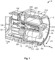
- FIG. 1 One embodiment of the connector 1 is illustrated in Fig. 1 , wherein the connector 1 has a connector housing 3 or an external housing 3 on/in which the exchangeable power-electric contact module 2 or an exchangeable electric high-current contact module 2 or an exchangeable electro-power contact module 2 is illustrated in its mounted position.
- the contact module 2 comprises an insert housing 20 or a contact module housing 20 which is configured substantially in the form of a vessel in the present case. It goes without saying that a substantially disc-like (only base plate 200, cf. below), a substantially cage-like or a substantially tub-like configuration etc. can also be used.
- the insert housing 20 comprises at least one base plate 200 which can be configured as a disc 200, a plate etc.
- the base plate 200 has at least one contact section receptacle 201 for holding a respective contact apparatus 110/120, in particular a first contact apparatus 110, of a contact device 10.
- the contact apparatus 110 (, 120) by way of its contact apparatus mounting section 111 (, 121), is accommodated in the contact section receptacle 201.
- a collar 114 which may be present, on an axial end of the mounting section 111 (, 121) prevents the contact apparatus 110 (,120) from being inserted too far into the insert housing 20.
- At least one protective sleeve 210 or protective nozzle 210 extends away from the base plate 200, it being possible for the contact apparatus 110 (,120) or possibly at least the actual contact region 113 of the said contact apparatus to be received in the said protective sleeve or protective nozzle in such a way that a worker cannot come into contact with the contact apparatus 110 (,120) which is, possibly partially, accommodated in a contact section receptacle 211 of the protective sleeve 210.
- the protective sleeve 210 is preferably configured in a substantially hollow-cylindrical manner.
- a side wall 200 which is provided possibly at a radial outside wheel of the base plate 200 may make it easier to insert the contact module 2 into the connector housing 3.
- the side wall 220 can run substantially completely around the outside wheel of the base plate 200 in the circumferential direction Um.
- the connector housing 3 can have a possibly substantially completely circumferential shroud 320.
- the base plate 200 and the connector housing 3 or the side wall 220 and the shroud 320 have, possibly in sections, complementary latching devices which can preferably be released from one another, as a result of which the contact module 2 can be fixed on/in the connector housing 3.
- a respective contact apparatus 120, 110 of the contact device 10, in particular a second contact apparatus 120 can be held by means of the connector housing 3.
- the connector housing 3 has a contact section receptacle 301, wherein the contact apparatus 120 (, 110), by way of its contact apparatus mounting section 121 (, 111), is received in the contact section receptacle 301.
- a collar 124 which may be present, at an axial end of the mounting section 121 (, 111) defines a stop for the collar 114 of the other contact apparatus 110 (, 120) and serves possibly as an axial stop for a contact device seal 130.
- the contact apparatus 120 (, 110) is preferably received in a rotationally fixed manner in the contact section receptacle 301 of the connector housing 3 or in the connector housing 3. Further, the contact apparatus 110 (, 120) is likewise preferably received in a rotationally fixed manner in the contact section receptacle 201 and the protective sleeve 210, or in the contact module 2.
- the two contact apparatuses 110, 120 e.g. possibly apart from spring slots, are configured in a substantially rotationally symmetrical manner in a socket region 113 or a contact region 113 which is configured as a tab contact.
- the connector 1 according to the invention is designed in such a way that the contact module 2 can be removed from the connector 1 or taken out of the connector 1 and can be replaced by a second contact module 2, if e.g. a contact region 113 of the contact apparatus 110 (, 120) exhibits an excessive amount of wear. As a result, it is not necessary for the entire connector 1 to be replaced, but rather only a part thereof.
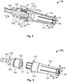
- Figs 1 to 3 show a mounted contact device 10 and Fig. 3 shows a demounted contact device 10.
- the contact device 10 is configured in such a way that the two contact apparatuses 110, 120 of the said contact device can be inserted one into the other or one onto the other and can be disconnected from one another again in a correspondingly linear manner, this being illustrated by the two wide arrows in Fig. 2 .
- a first contact section 110 or the first contact apparatus 110 of the contact device 10 comprises, on a free longitudinal end section, a contact region 113 which is configured as a socket region 113.
- a housing mounting section 112 which is not configured as a sealing seat in the present case, adjoins the contact region 113 axially further to the rear.
- a contact apparatus mounting section 111 which is configured as a contact spring ring 111, e.g. in the form of a socket, in turn adjoins the said housing mounting section axially further to the rear.
- a collar 114 is preferably formed between the housing mounting section 112 and the contact apparatus mounting section 111 in the first contact apparatus 110.
- a second contact section 120 or the second contact apparatus 120 of the contact device 10 comprises, on a free longitudinal end section, a housing mounting section 122 which is preferably configured as a sealing seat in the present case.
- a collar 124 is preferably formed at the free end of the housing mounting section 122.
- a contact apparatus mounting section 121 which is configured as a contact pin 121 or a contact bolt 121 is provided within the housing mounting section 122, wherein the contact apparatus mounting section 121 can be provided partially or substantially completely within the housing mounting section 122 which is hollow, apart from the contact pin 121.
- a connecting region 123, which is preferably configured as a crimp region 123, of the second contact apparatus 120 adjoins the housing mounting section 122 and the contact apparatus mounting section 121 axially further to the rear.
- a fixing region 125 for fixing the contact apparatus 125 is preferably provided between the said connecting region and housing mounting section, for which purpose a corresponding latching device or latching apparatus can engage or act in/on the fixing region 125.
- the latching device or latching apparatus can be a section of the connector housing 3 or else an external component part or can be formed on an external component part.
- the second contact apparatus 120 it is possible to configure the second contact apparatus 120 in such a way that the contact pin 121 protrudes out of the housing mounting section 122.
- a free longitudinal end section of the contact pin 121 can engage into a centring recess 115 of the first contact apparatus 110 when the contact device 10 is in a mounted state, wherein the centring recess 115 is formed on the inside of the housing mounting section 112 of the first contact apparatus 110.
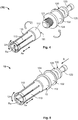
- Fig. 4 shows a demounted contact device 10
- Fig. 5 shows a mounted contact device 10.
- the contact device 10 is configured in such a way that the two contact apparatuses 110, 120 of the said contact device can be screwed to one another, this being indicated by the two wide arrows in Fig. 4 . Accordingly, the two contact apparatuses 110, 120 can be disconnected from one another again by means of an opposite rotational movement.
- a first contact section 110 or the first contact apparatus 110 of the contact device 10 comprises, on a free longitudinal end section, a contact region 113 which is configured as a socket region 113.
- a housing mounting section 112 which is not configured as a sealing seat in the present case, adjoins the contact region 113 axially further to the rear.
- a contact apparatus mounting section 111 which is configured as an internal thread 111 (threaded recess 111) is provided within the housing mounting section 112 and is preferably provided completely within the housing mounting section 112.
- the first contact apparatus 110 preferably does not have a collar.
- a second contact section 120 or the second contact apparatus 120 of the contact device 10 comprises, on a free longitudinal end section, a contact apparatus mounting section 121 which is configured as an external thread 121 (threaded pin 121) and protrudes from the second contact apparatus 120.
- a housing mounting section 122 adjoins the said contact apparatus mounting section axially further to the rear, wherein a collar 124 is preferably formed between the contact apparatus mounting section 121 and the housing mounting section 122.
- the housing mounting section 122 is preferably configured as a sealing seat in the present case.
- a connecting region 123 which is preferably configured as a crimp region 123, of the second contact apparatus 120 adjoins the housing mounting section 122 axially further to the rear.
- a fixing region 125 for fixing the contact apparatus 125 is preferably provided between the said connecting region and housing mounting section, for which purpose a corresponding latching device or latching apparatus can engage or act in/on the fixing region 125.
- the latching device or latching apparatus can again be a section of the connector housing 3 or else an external component part or can be formed on an external component part.
Landscapes
- Connector Housings Or Holding Contact Members (AREA)
- Details Of Connecting Devices For Male And Female Coupling (AREA)
Abstract
Description
- The invention relates to a power-electric contact device, in particular an electric high-current contact device or an electro-power contact device, for a power-electric connector. The invention further relates to an exchangeable power-electric contact module, in particular an exchangeable electric high-current contact module or an exchangeable electro-power contact module, for a power-electric connector. The invention furthermore relates to a power-electric connector or a power-electric mating connector, in particular an electric high-current connector or an electro-power connector, e.g. for the three-phase current sector or the electric vehicle sector.
- In the electrical sector (electrical engineering, electrics, electrical power engineering etc.), a large number of electrical connector apparatuses or connector devices, socket and/or pin connectors etc. - called ((power-) electric) (mating) connectors in the text which follows - are known which serve the purpose of transmitting electric currents, voltages and/or signals at a wide range of currents, voltages and/or frequencies. In the low-voltage, medium-voltage or high-voltage range and/or in the medium-current or high-current range, and in particular in the three-phase current sector, connectors of this kind have to ensure transmission of current, voltage and/or signals in warm, possibly hot, contaminated, humid and/or chemically aggressive environments permanently, repeatedly and/or after a comparatively long service life, possibly at short notice.
- Owing to a wide range of applications, a large number of connectors of special design are known. Connectors of this kind or the housings of connectors of this kind can be installed on an electrical cable, a line etc. and/or an electric device or apparatus, e.g. on/in a housing of a (power-) electric component or a device, assembly etc. of this kind; in the latter case, the connector is often referred to as a (mating) connector device. If a connector is located only on a cable etc., the said connector is usually referred to as a (flying) (plug) connector or a plug (usually with pin contact devices) or a coupling (usually with socket contact devices); if the said connector is located on/in a (power-) electric component, it is usually referred to as a (built-in) connector, such as a (built-in) plug or a (built-in) socket.
- Power-electric connectors have to ensure problem-free transmission of electric power, wherein connectors (connectors and mating connectors) which correspond to one another usually have fastening or locking devices for permanently, but generally releasably, fastening or locking the connector to/in the mating connector. Further, corresponding power-electric contact devices, e.g. a socket contact device, a pin contact device, a tab contact device etc., have to be securely accommodated in the said connector. Efforts are continuously being made to improve power-electric connectors and/or to make the said power-electric connectors more cost-effective.
- By way of example, charging connectors for electric vehicles require power-electric contact devices which have to transport an electric current (power contact device, grounding contact device) of approximately 32 A at outside temperatures of approximately -30°C to approximately +50°C and at a peak electric voltage of approximately 500 V. Signal contact devices have a current of approximately 2 A at a voltage of 30 V. The service life of charging connectors of this kind should be approximately or at least 10 to 15 years, wherein, depending on the environment (moisture, sand, salt etc.), it should be possible to carry out 10,000 to 20,000 plug connection cycles with a charging connector of this kind, wherein it is preferred when permanently low contact resistances are also realized. In order to realize such numbers of plug connection cycles with comparatively low contact resistances, the contact devices have to be coated, this again adding to the cost of the contact devices.
- An object of the invention is to specify an improved power-electric connector or an improved power-electric mating connector, in particular an electric high-current connector or an electro-power connector, for example for the three-phase current sector or the electric vehicle sector. In this case, the connector should be designed for 10,000 to 20,000 plug connection cycles depending on an environment in which the connector is used, wherein the contact devices of the said connector should be comparatively cost-effective. In particular, it should be possible to dispense with comparatively costly coating of the contact devices in this case.
- The object of the invention is achieved by means of a power-electric contact device, in particular an electric high-current contact device or an electro-power contact device, for a power-electric connector; by means of an exchangeable power-electric contact module, in particular an exchangeable electric high-current contact module or an exchangeable electro-power contact module, for a power-electric connector; as well as by means of a power-electric connector or a power-electric mating connector, in particular an electric high-current connector or an electro-power connector; preferably for the three-phase current sector or the electric vehicle sector - according to the independent claims. - Advantageous developments, additional features and/or advantages of the invention are set forth in the dependent claims and the following description.
- The power-electric contact device according to the invention comprises a power-electric contact section and a power-electric connecting section, wherein the contact section is configured as a first power-electric contact apparatus and the connecting section is configured as a second power-electric contact apparatus. Power-electric is intended to mean that the contact device is suitable e.g. for electric voltages above 24 V, in particular of above 48 V, for example of approximately 500 V; for electric currents above 4 A, in particular of above 12 A, for example of approximately 32 A; and/or for signals of above 500 mA, in particular of above 1 A, for example of approximately 2 A. It goes without saying that values above these can be used.
- The contact device or the first contact apparatus may be configured for an exchangeable power-electric contact module in this case. The two contact apparatuses for an individual contact device can be configured separately from one another. The two contact apparatuses which can be separated from one another or which can be mounted one on the other can furthermore comprise in each case a power-electric contact region in which they can be electrically disconnected from one another or can be electrically connected to one another. In this case, the two contact apparatuses can further comprise a mechanical contact region in which they can be mechanically disconnected from one another or can be connected to one another.
- According to the invention, the contact device is configured at least in two parts. In this case, the contact apparatuses can be held together in one piece as a contact device. That is to say, the (at least) two parts of an individual contact device, that is to say the first contact apparatus and the second contact apparatus, are configured separately from one another, that is to say individually or electrically and/or mechanically disconnected from one another, before mutual mounting thereof. - In embodiments, the first contact apparatus and the second contact apparatus can be electromechanically coupled to one another by means of a single releasable connection. The electromechanical connection can be configured as a positive and/or non-positive connection, wherein the connection is preferably configured as a plug connection, a screw connection, a latching connection or a snap-action connection.
- In this case, the electromechanical connection is preferably configured with a complementary shape and/or a complementary function (at least) in sections. Further, a weak cohesive connection (contact paste, detachable adhesive) can be provided within the connection. The connection of the contact device can be configured in such a way that the first contact apparatus can be easily separated from the second contact apparatus, and vice versa, by hand and/or by means of a tool. This is preferably done without damaging one of the two contact apparatuses. In particular, this is done in such a way that the contact apparatus which is not intended to be exchanged is not damaged when the respective other contact apparatus is exchanged.
- In embodiments, the first contact apparatus has a contact region with which electrical and/or mechanical contact can be made by a power-electric mating contact device. In embodiments, the second contact apparatus has a connecting region to which an electric cable can be electrically connected. - In embodiments, the first contact apparatus can have a contact apparatus mounting section on/in which the second contact apparatus is mountable or is mounted. Further, the second contact apparatus can have a contact apparatus mounting section on/in which the first contact apparatus is mountable or is mounted. In this case, the contact apparatus mounting sections can be configured with a complementary shape and/or a complementary function in sections.
- In embodiments, the first contact apparatus can have a housing mounting section by way of which it is mountable or is mounted indirectly or directly on/in a contact section receptacle. Further, the second contact apparatus can have a housing mounting section by way of which it is mountable or is mounted indirectly or directly on/in a connector housing. In this case, the housing mounting sections cannot be configured with a complementary shape or a complementary function. - In the case of a mounted contact device, the contact apparatus mounting sections of the said mounted contact device constitute the electromechanical connection or the electrical and mechanical contact region.
- In this case, the contact apparatus mounting sections are preferably guided one into the other in sections. Further, the contact apparatus mounting sections overlap in this case preferably in the axial direction and/or radial direction of the contact device. Furthermore, the contact apparatus mounting sections can be mutually centred. That is to say, the contact apparatus mounting section of one contact apparatus is centred e.g. radially on the outside of the contact apparatus mounting section possibly within the other contact apparatus, whereas the contact apparatus mounting section of the other contact apparatus is centred radially on the inside of the contact apparatus (possibly on the inside of the contact apparatus mounting section or even on the inside of the housing mounting section).
- Further, the housing mounting sections of a mounted contact device can be spaced apart from one another in the axial direction, wherein the housing mounting sections can have a substantially equal or an unequal (outside) diameter or equal or unequal (outside) dimensions. - It is possible for a housing mounting section of an individual contact apparatus to be provided radially beyond or outside the contact apparatus mounting section of the said individual contact apparatus. Further, a housing mounting section and a contact apparatus mounting section of the same contact apparatus can overlap preferably in the axial direction; that is to say e.g. that the contact apparatus mounting section can protrude possibly slightly into the inside of the housing mounting section. It goes without saying that it is possible to provide the housing mounting section at a distance from the contact apparatus mounting section of the same contact apparatus preferably in the axial direction.
- The contact apparatus mounting section of the first contact apparatus can comprise a contact spring ring or a contact pin. The contact apparatus mounting section of the second contact apparatus can analogously comprise a contact pin or a contact spring ring. - Further, the contact apparatus mounting section of the first contact apparatus can comprise an internal thread (threaded recess) or an external thread (threaded pin). The contact apparatus mounting section of the second contact apparatus can analogously comprise an external thread (threaded pin) or an internal thread (threaded recess).
- In embodiments, the contact device can be configured as a socket contact device, a pin contact device or a tab contact device. It goes without saying that other contact devices can be used. The first contact apparatus can be configured, possibly partially, as a contact section, in particular as a socket contact, of the contact device. It goes without saying that the first contact apparatus can also be configured, possibly partially, as a pin contact, a tab contact etc.
- A power-electric mating contact device or a power-electric mating contact apparatus is configured in an analogous manner and/or in a complementary manner in sections (e.g. a pin contact or a tab contact in relation to a socket contact), wherein the terms contact device and mating contact device, contact apparatus and mating contact apparatus can be used synonymously. This can also be applied to a connector and a mating connector (also see below). - Further, the second contact apparatus can be configured, possibly partially, as a connecting section for a cable, in particular as a crimp connection of the contact device. It goes without saying that a (compacting) weld connection, a solder connection, an adhesive connection, a plug connection, a screw connection etc. can, possibly partially, also be used here.
- The first contact apparatus and/or the second contact apparatus can be of one-piece or integral configuration in material terms. - In the case of one-piece configuration in material terms, individual parts of a contact apparatus (if any) are fixed to one another cohesively, e.g. by means of welding, soldering, adhesive bonding, and preferably cannot be separated into individual parts without damaging the configuration. The said individual parts can further be physically held together by means of a positive connection and/or non-positive connection. In the case of an integral configuration, there is only one single component part which can be separated more or less only if it is destroyed. Therefore, an integral contact apparatus is manufactured from a single piece which, for its part, can be integral or monolithic.
- In embodiments, the first contact apparatus and/or the second contact apparatus can be uncoated. In this case, uncoated is intended to mean that an actual material of the contact apparatus in question is open to the air and not, possibly partially, provided under a coating which contains e.g. nickel. The first contact apparatus and/or the second contact apparatus can be configured from a copper alloy, in particular brass. A copper alloy of this kind can be, for example, CuZn37Pb2 or CuZn35Pb2.
- In embodiments, the housing mounting section of the second contact apparatus can be configured as a sealing seat for a fluid seal. Further, the contact device can be configured as a subassembly, wherein the subassembly can have a contact device seal. In this case, the contact device seal can be mountable or mounted e.g. on the housing mounting section.
- The exchangeable power-electric contact module according to the invention comprises an insert housing having at least one contact section receptacle, wherein a power-electric contact apparatus of a power-electric contact device can be provided or is provided on/in the contact section receptacle. In this case, the contact apparatus can be received or is received e.g. on/in the contact section receptacle at least in sections in a positive and/or non-positive manner. For example, the contact apparatus can be latched or is latched, can be clipped or is clipped and/or can be adhesively bonded or is adhesively bonded etc. for example to/in the contact section receptacle.
- In embodiments, the insert housing can comprise a base plate having a plurality of contact section receptacles through which a plurality of contact apparatuses are inserted. In this case, at least the base plate can constitute the insert housing of the contact module, wherein the insert housing is substantially in the shape of a disc (base plate, plate) or further of an (open) cage, an (open) tub or a vessel. A plurality of protective sleeves in each of which a contact section receptacle is provided can extend away from the base plate. The contact apparatuses can be (partially) received in the contact section receptacles of the protective sleeves.
- In embodiments, the base plate can be of one-piece or integral configuration with the protective sleeves in material terms. Further, the insert housing can be of one-piece or integral configuration in material terms. Analogously see above in respect of one-piece or integral configuration in material terms. The insert housing can have a latching device or a latching apparatus for latching with a connector housing. A latching device can be configured e.g. as a latching spring, a latching arm, a latching lug etc. Further, a latching apparatus can be configured e.g. as a latching element, a latching projection, a latching lug, a latching shoulder, a latching border, a latching edge, a latching recess, a latching passage recess etc. The contact module can have a contact device or a first contact apparatus according to the invention.
- The power-electric connector according to the invention or the power-electric mating connector according to the invention comprises a connector housing, wherein the connector housing has at least one contact section receptacle, and wherein a power-electric contact apparatus of a power-electric contact device is provided in the contact section receptacle. In this case, the contact device can be configured as a contact device according to the invention. Further, the connector or the mating connector can have an exchangeable power-electric contact module according to the invention. In this case, the connector or the mating connector can have a contact securing device for securing the contact device or a contact device of the contact module. In this case, a or the contact securing device can be provided separately and/or within the connector housing.
- The connector or the mating connector can be configured as a plug, a coupling, a plug socket or a built-in connector.
- Further, the connector or the mating connector can be configured as a three-phase current connector or a charging connector. The connector housing can have a latching device or a latching apparatus for latching with an insert housing of the contact module (see above in respect of the latching device or latching apparatus). Related latching devices, related latching apparatuses or a latching device which is related to a latching apparatus and vice versa can form a positive and/or non-positive combination in a mounted state. In this case, the combination is preferably configured with a complementary shape and/or a complementary function in sections.
- The invention is explained in more detail below using exemplary embodiments with reference to the attached detailed drawing, which is not true to scale. Elements, component parts or components which have an identical, univocal or similar configuration and/or function are provided with the same reference symbols in the description of the figures, the list of reference symbols and the patent claims and identified by the same reference symbols in the figures (Fig.) of the drawing. Possible alternatives, steady-state and/or kinematic reversals, combinations, etc., which are not explained in the description, are not illustrated in the drawing and/or are not exclusive, with respect to the explained exemplary embodiments of the invention or individual assemblies, parts or sections thereof are set forth in the list of reference symbols.
- All of the features explained, including those in the list of reference symbols, can be used not only in the specified combination or the specified combinations but also in another combination or other combinations or on their own.
- In particular, it is possible to replace a feature or a plurality of features in the description of the invention and/or the description of the figures on the basis of the reference symbols and the features, which are associated with the said reference symbols, in the description of the invention, the description of the figures and/or the list of reference symbols. Further, a feature or a plurality of features in the patent claims can be interpreted, specified in more detail and/or substituted as a result. - In the figures, which are merely exemplary:
- Fig. 1
- shows a laterally centrally sectioned perspective view of an embodiment of a connector (mating connector) according to the invention with an embodiment of a contact device according to the invention, obliquely from the front;
- Fig. 2
- likewise shows a laterally centrally sectioned perspective view of the embodiment of the power-electric contact device from
Fig. 1 in a state in which the two contact apparatuses of the said contact device are plugged together, obliquely from the front; - Fig. 3
- shows a view which is analogous to
Fig. 2 of the embodiment of the contact device fromFig. 2 in a demounted state, wherein the two contact apparatuses of the contact device are separated from one another; - Fig. 4
- shows a perspective view of a further embodiment of the power-electric contact device according to the invention in a state in which the two contact apparatuses of the said contact device are screwed together, obliquely from the front and above; and
- Fig. 5
- shows a view which is analogous to
Fig. 4 of the second embodiment of the contact device fromFig. 4 in a demounted state, wherein the two contact apparatuses of the contact device are separated from one another. - The invention is explained in more detail below with reference to two embodiments (
Figs 1 to 3 as well asFigs 4 and 5 ) of a power-electric contact device 10, in particular for a copper or aluminium cable, for the three-phase current sector or the electric vehicle sector, as well as an embodiment of an exchangeable power-electric contact module 2 and an embodiment of a power-electric connector 1 (bothFig. 1 ). The information given in respect of aconnector 1 and acontact device 10 is also intended to apply to amating connector 1 and, respectively, to amating contact device 10. That is to say, these designations are to be interpreted as being synonymous. - The invention is not restricted to embodiments of this kind, but is more basic in nature, with the result that it can be used for other contact devices in the vehicle sector or a non-vehicle sector, e.g. an electrical engineering sector, an energy related sector etc. That is to say, other variations can be derived therefrom, without departing from the scope of protection of the invention. - In this case, the following statements relate to an axial direction Ax (axial), a longitudinal axis Ax or a rotation axis Ax, a radial direction Ra (radial) as well as a circumferential direction Um (tangential) of the
connector 1, of thecontact device 10 and/or ofcontact apparatuses contact device 10, wherein two such directions are possible in each case. - The power-electric (high-current/electro-power) (mating)
connector 1 according to the invention which is configured in a linear manner in the present case is configured as a plug 1 (high-current plug 1, chargingplug 1, shroudedplug 1 etc.) or a coupling 1 (high-current coupling 1, chargingcoupling 1, shroudedcoupling 1 etc.). It goes without saying that it is possible to configure theconnector 1 in an angled or curved manner. Further, theconnector 1 can be configured as a plug socket, a built-in connector etc. The power-electric (high-current/electro-power)contact device 10 according to the invention which is likewise configured in a linear manner in the present case is configured as acrimp contact device 10, wherein thecontact device 10 is further configured as asocket contact device 10. - It goes without saying that it is possible to configure the
contact device 10 as a pin contact device, a tab contact device etc. Furthermore, thecontact device 10 can be configured as a non-power-electric contact device 10, that is to say as anelectric contact device 10. Further, thecontact device 10 can be configured as a (compacting) weld contact device, a solder contact device etc. (see below). It goes without saying that it is possible to also configure thecontact device 10 in an angled or curved manner. - According to the invention, the
contact device 10 is configured in several parts, in particular in two parts. That is to say, at least two sections or constituent parts of asingle contact device 10 can be mechanically, electrically and/or electromechanically disconnected from one another and possibly joined together again. In this case, the two sections or constituent parts can be produced separately from one another, or the two sections or constituent parts are formed from a one-piece or integral part (contact device 10) in material terms. - The
contact device 10 preferably comprises two (power-electric, electric)contact apparatuses contact apparatus 110 can be configured as asocket contact 110, a pin contact, a tab contact etc., and thecontact apparatus 120 configured as a connectingapparatus 120 can be configured as acrimp connection 120, a (compacting) weld connection, a solder connection, an adhesive connection, a plug connection, a screw connection etc. in this case. The contact apparatuses 110, 120 are held together in one piece, but in an easily releasable manner, ascontact device 10. - The two
contact apparatuses individual contact device 10, in a state in which they are mounted one on the other (cf.Figs 1 ,2 and5 ), constitute acontact region 15 or aconnection 15 in which contact region or in which connection the said contact apparatuses can be mechanically, electrically and/or electromechanically disconnected from one another and possibly joined together again. Thiscontact region 15 can be configured in sections as a positive and/ornon-positive connection 15. By way of example, a (spring) plug connection (cf.Figs 1 to 3 ), a screw connection (cf.Figs 4 and 5 ), a latching connection, a snap-action connection (clip arrangement etc.) etc. is used for this purpose. - Preferably, a
contact section 110 of thecontact device 10 is configured as thefirst contact apparatus 110, and a connectingsection 120 of thecontact device 10 is configured as thesecond contact apparatus 120 of thecontact device 10. That is to say, thecontact device 10 has twosections sections common contact region 15 of the twosections contact device 10. - For mutual mounting of two
contact apparatuses contact apparatus apparatus mounting section contact apparatuses contact region 15 of anindividual contact device 10 between them. The contactapparatus mounting sections - Preferably, contact
apparatus mounting sections sections plug connection 111, 121 (cf.Figs 1 to 3 ), a screw connection (cf.Figs 4 and 5 ), a latching connection, a snap-action connection (clip arrangement etc.) etc. - Therefore, it is e.g. possible to configure a contact
apparatus mounting section 111/121 as a contact pin/contact spring ring 111/121 and to configure the contactapparatus mounting section 121/111 which corresponds thereto or is complementary thereto in sections as a contact spring ring/contact pin 121/111 (cf.Figs 1 to 3 ). Further, it is for example possible to configure a mountingsection 111/121 as an internal thread (threaded recess)/external thread (threaded pin) 111/121 and to configure the contactapparatus mounting section 121/111 which corresponds thereto or is complementary thereto in sections as an external thread (threaded pin)/internal thread (threaded recess) 121/111 (cf.Figs 4 and 5 ). It goes without saying that otherelectromechanical connections 15 for the contactapparatus mounting sections - At least one of the
contact apparatuses housing mounting section contact device 10 on/in ahousing housing mounting section 112/122 of thecontact device 10 on one of thecontact apparatuses 110/120, a respectiveother contact apparatus 120/110 is preferably held on/in thehousing first contact apparatus 110/120. However, preferably, thecontact apparatuses 110/120 of anindividual contact device 10 each have ahousing mounting section - Further, the
contact device 10 or one of thecontact apparatuses contact region 113, and thecontact device 10 or one of thecontact apparatuses region 123. Acontact region 113 can be configured e.g. as asocket region 113, a pin region, a tab region etc. A connectingregion 123 can be configured e.g. as acrimp region 123, a (compacting) weld region, a solder region, an adhesive region, a plug region, a screw region etc. - Depending on a design of the
respective contact apparatus apparatus mounting section 111/121, the respectivehousing mounting section 112/122 and/or therespective contact region 113 or connectingregion 123 can be formed to be offset in relation to one another in the radial direction Ra and to overlap with one another, possibly partially, in the axial direction Ax, to be offset in relation to one another in the axial direction Ax and/or to be offset in relation to one another in the radial direction Ra in thecontact apparatus - Therefore, it is possible, in particular in the case of an
individual contact apparatus 110/120, to provide the contactapparatus mounting section 111/121 partially or substantially completely within thehousing mounting section 112/122 of thiscontact apparatus 110/120 (cf.Figs 1 to 3 ). In this case, unequal radii of the contactapparatus mounting section 111/121 and of thehousing mounting section 112/122 can be realized. - Further, in the case of anindividual contact apparatus 120/110, it is possible to provide the contactapparatus mounting section 121/111 at an axial distance from thehousing mounting section 122/112 of thiscontact apparatus 110/120. In this case, equal or unequal radii of the contactapparatus mounting section 121/111 and of thehousing mounting section 122/112 can be realized (cf.Figs 4 and 5 ). - Further, the
contact device 10 or one of thecontact apparatuses contact device seal 130. To this end, ahousing mounting section contact device seal 130 is seated in a sealing manner. In this case, thecontact device 10 having thecontact device seal 130 can be configured as asubassembly 10. - One embodiment of the
connector 1 is illustrated inFig. 1 , wherein theconnector 1 has aconnector housing 3 or anexternal housing 3 on/in which the exchangeable power-electric contact module 2 or an exchangeable electric high-current contact module 2 or an exchangeable electro-power contact module 2 is illustrated in its mounted position. Thecontact module 2 comprises aninsert housing 20 or acontact module housing 20 which is configured substantially in the form of a vessel in the present case. It goes without saying that a substantially disc-like (onlybase plate 200, cf. below), a substantially cage-like or a substantially tub-like configuration etc. can also be used. - The
insert housing 20 comprises at least onebase plate 200 which can be configured as adisc 200, a plate etc. Thebase plate 200 has at least onecontact section receptacle 201 for holding arespective contact apparatus 110/120, in particular afirst contact apparatus 110, of acontact device 10. In this case, the contact apparatus 110 (, 120), by way of its contact apparatus mounting section 111 (, 121), is accommodated in thecontact section receptacle 201. Acollar 114, which may be present, on an axial end of the mounting section 111 (, 121) prevents the contact apparatus 110 (,120) from being inserted too far into theinsert housing 20. - Preferably, at least one
protective sleeve 210 orprotective nozzle 210 extends away from thebase plate 200, it being possible for the contact apparatus 110 (,120) or possibly at least theactual contact region 113 of the said contact apparatus to be received in the said protective sleeve or protective nozzle in such a way that a worker cannot come into contact with the contact apparatus 110 (,120) which is, possibly partially, accommodated in acontact section receptacle 211 of theprotective sleeve 210. Theprotective sleeve 210 is preferably configured in a substantially hollow-cylindrical manner. - A
side wall 200 which is provided possibly at a radial outside wheel of thebase plate 200 may make it easier to insert thecontact module 2 into theconnector housing 3. In this case, theside wall 220 can run substantially completely around the outside wheel of thebase plate 200 in the circumferential direction Um. Analogously to this, theconnector housing 3 can have a possibly substantially completelycircumferential shroud 320. Thebase plate 200 and theconnector housing 3 or theside wall 220 and theshroud 320 have, possibly in sections, complementary latching devices which can preferably be released from one another, as a result of which thecontact module 2 can be fixed on/in theconnector housing 3. - According to the invention, a
respective contact apparatus contact device 10, in particular asecond contact apparatus 120, can be held by means of theconnector housing 3. To this end, theconnector housing 3 has acontact section receptacle 301, wherein the contact apparatus 120 (, 110), by way of its contact apparatus mounting section 121 (, 111), is received in thecontact section receptacle 301. Acollar 124, which may be present, at an axial end of the mounting section 121 (, 111) defines a stop for thecollar 114 of the other contact apparatus 110 (, 120) and serves possibly as an axial stop for acontact device seal 130. - The contact apparatus 120 (, 110) is preferably received in a rotationally fixed manner in the
contact section receptacle 301 of theconnector housing 3 or in theconnector housing 3. Further, the contact apparatus 110 (, 120) is likewise preferably received in a rotationally fixed manner in thecontact section receptacle 201 and theprotective sleeve 210, or in thecontact module 2. Preferably, the twocontact apparatuses socket region 113 or acontact region 113 which is configured as a tab contact. - The
connector 1 according to the invention is designed in such a way that thecontact module 2 can be removed from theconnector 1 or taken out of theconnector 1 and can be replaced by asecond contact module 2, if e.g. acontact region 113 of the contact apparatus 110 (, 120) exhibits an excessive amount of wear. As a result, it is not necessary for theentire connector 1 to be replaced, but rather only a part thereof. - The embodiment of the
contact device 10 shown inFigs 1 to 3 is explained in more detail below, whereinFigs 1 and2 show amounted contact device 10 andFig. 3 shows ademounted contact device 10. In this case, thecontact device 10 is configured in such a way that the twocontact apparatuses Fig. 2 . - A
first contact section 110 or thefirst contact apparatus 110 of thecontact device 10 comprises, on a free longitudinal end section, acontact region 113 which is configured as asocket region 113. Ahousing mounting section 112, which is not configured as a sealing seat in the present case, adjoins thecontact region 113 axially further to the rear. A contactapparatus mounting section 111 which is configured as acontact spring ring 111, e.g. in the form of a socket, in turn adjoins the said housing mounting section axially further to the rear. Acollar 114 is preferably formed between thehousing mounting section 112 and the contactapparatus mounting section 111 in thefirst contact apparatus 110. - A
second contact section 120 or thesecond contact apparatus 120 of thecontact device 10 comprises, on a free longitudinal end section, ahousing mounting section 122 which is preferably configured as a sealing seat in the present case. Acollar 124 is preferably formed at the free end of thehousing mounting section 122. A contactapparatus mounting section 121 which is configured as acontact pin 121 or acontact bolt 121 is provided within thehousing mounting section 122, wherein the contactapparatus mounting section 121 can be provided partially or substantially completely within thehousing mounting section 122 which is hollow, apart from thecontact pin 121.
A connectingregion 123, which is preferably configured as acrimp region 123, of thesecond contact apparatus 120 adjoins thehousing mounting section 122 and the contactapparatus mounting section 121 axially further to the rear. A fixingregion 125 for fixing thecontact apparatus 125 is preferably provided between the said connecting region and housing mounting section, for which purpose a corresponding latching device or latching apparatus can engage or act in/on the fixingregion 125. In this case, the latching device or latching apparatus can be a section of theconnector housing 3 or else an external component part or can be formed on an external component part. - As shown in
Figs 1 to 3 , it is possible to configure thesecond contact apparatus 120 in such a way that thecontact pin 121 protrudes out of thehousing mounting section 122. In this case, a free longitudinal end section of thecontact pin 121 can engage into acentring recess 115 of thefirst contact apparatus 110 when thecontact device 10 is in a mounted state, wherein thecentring recess 115 is formed on the inside of thehousing mounting section 112 of thefirst contact apparatus 110. - It goes without saying that it is possible to provide the contact
apparatus mounting section 111 of thefirst contact apparatus 110 on thesecond contact apparatus 120 and, analogously thereto, to provide the contactapparatus mounting section 121 of thesecond contact apparatus 120 on thefirst contact apparatus 110. Further, it is possible to use an arrangement of the external thread 121 (threaded pin 121) and the internal thread 111 (threaded recess 111) or an arrangement of the internal thread 111 (threaded recess 111) and the external thread 121 (threaded pin 121), instead of an arrangement of thecontact spring ring 111 and thecontact pin 121, analogously to the following embodiment. - The embodiment of the
contact device 10 shown inFigs 4 and 5 is explained in more detail below, whereinFig. 4 shows ademounted contact device 10 andFig. 5 shows amounted contact device 10. In this case, thecontact device 10 is configured in such a way that the twocontact apparatuses Fig. 4 . Accordingly, the twocontact apparatuses - A
first contact section 110 or thefirst contact apparatus 110 of thecontact device 10 comprises, on a free longitudinal end section, acontact region 113 which is configured as asocket region 113. Ahousing mounting section 112, which is not configured as a sealing seat in the present case, adjoins thecontact region 113 axially further to the rear. A contactapparatus mounting section 111 which is configured as an internal thread 111 (threaded recess 111) is provided within thehousing mounting section 112 and is preferably provided completely within thehousing mounting section 112. Thefirst contact apparatus 110 preferably does not have a collar. - A
second contact section 120 or thesecond contact apparatus 120 of thecontact device 10 comprises, on a free longitudinal end section, a contactapparatus mounting section 121 which is configured as an external thread 121 (threaded pin 121) and protrudes from thesecond contact apparatus 120. Ahousing mounting section 122 adjoins the said contact apparatus mounting section axially further to the rear, wherein acollar 124 is preferably formed between the contactapparatus mounting section 121 and thehousing mounting section 122. Thehousing mounting section 122 is preferably configured as a sealing seat in the present case. - A connecting
region 123, which is preferably configured as acrimp region 123, of thesecond contact apparatus 120 adjoins thehousing mounting section 122 axially further to the rear. A fixingregion 125 for fixing thecontact apparatus 125 is preferably provided between the said connecting region and housing mounting section, for which purpose a corresponding latching device or latching apparatus can engage or act in/on the fixingregion 125. In this case, the latching device or latching apparatus can again be a section of theconnector housing 3 or else an external component part or can be formed on an external component part. - It goes without saying that it is possible to provide the contact
apparatus mounting section 111 of thefirst contact apparatus 110 on thesecond contact apparatus 120 and, analogously thereto, to provide the contactapparatus mounting section 121 of thesecond contact apparatus 120 on thefirst contact apparatus 110. Further, it is possible to use an arrangement of thecontact spring ring 111 and thecontact pin 121 or an arrangement of thecontact pin 121 and thecontact spring ring 111, instead of an arrangement of the internal thread 111 (threaded recess 111) and the external thread 121 (threaded pin 121), analogously to the above embodiment. -
- 1
- (Power-electric) (high-current/electro-power) (mating) connector, for example (flying) plug, (flying) coupling, plug socket, built-in connector, linear, angled or bent, for example for the three-phase current sector, the electric vehicle sector etc., e.g. high-current plug/coupling, charging plug/coupling, shrouded plug/coupling etc. for an electric cable, an electric line etc.
- 2
- Exchangeable power-electric contact module, exchangeable electric high-current contact module, exchangeable electro-power contact module
- 3
- Housing, connector housing, external housing for the
contact module 2 - 10
- Power-electric (high-current/electro-power) (mating) contact device, linear, angled or bent, e.g. socket contact device, pin contact device, tab contact device etc. and/or e.g. crimp contact device, (compacting) weld contact device, solder contact device etc., possibly can be provided as a subassembly, possibly with a
contact device seal 130 - 15
- Electrically, mechanically and/or electromechanically releasable contact region or connection between the
contact apparatuses - 20
- Housing, insert housing, contact module housing, disc-like (only base plate 200), cage-like, tub-like, vessel-like etc.
- 110
- Contact section of the
contact device 10, (first) power-electric contact apparatus, contact making device, e.g. socket contact, pin contact, tab contact etc. - 111
- Contact apparatus mounting section, contact spring ring/contact pin, internal thread (threaded recess)/external thread (threaded pin)
- 112
- Housing mounting section, possibly configured as sealing seat
- 113
- Contact region, socket region, pin region, tab region etc.
- 114
- Collar
- 115
- Centring recess
- 120
- Connecting section of the
contact device 10, (second) power-electric contact apparatus, connecting apparatus, e.g. crimp connection, (compacting) weld connection, solder connection, adhesive connection, plug connection, screw connection etc. - 121
- Contact apparatus mounting section, contact pin/contact spring ring, external thread (threaded pin)/internal thread (threaded recess)
- 122
- Housing mounting section, possibly configured as sealing seat
- 123
- Connecting region, crimp region, (compacting) weld region, solder region, adhesive region, a plug region, a screw region etc.
- 124
- Collar
- 125
- Fixing region for fixing the
contact apparatus 125 - 130
- Contact device seal
- 200
- Base plate, disc, plate
- 201
- Contact section receptacle for holding the first contact apparatus 110 (contact apparatus mounting section 111)
- 210
- Protective sleeve, protective nozzle
- 211
- Contact section receptacle for receiving the
first contact apparatus 110 or theactual contact region 113 - 220
- Side wall (optional)
- 301
- Contact section receptacle for holding the second contact apparatus 120 (contact apparatus mounting section 121), possibly by means of
contact device seal 130 - 320
- Shroud
- Ax
- Axial direction(s), longitudinal axis, rotation axis of the
connector 1, of thecontact device 10, of thecontact apparatus - Ra
- Radial direction(s) of the
connector 1, of thecontact device 10, of thecontact apparatus - S
- Plug-in direction of the
connector 1, of thecontact device 10, of thecontact apparatus - Um
- Circumferential direction(s) of the
connector 1, of thecontact device 10, of thecontact apparatus
Claims (12)
- Power-electric contact device (10), in particular electric high-current contact device (10) or electro-power contact device (10), for a power-electric connector (1), preferably for the three-phase current sector or for the electric vehicle sector, wherein the contact device (10) comprises a power-electric contact section (110) and a power-electric connecting section (120), characterized in that
the contact section (110) is configured as a first power-electric contact apparatus (110) and the connecting section (120) is configured as a second power-electric contact apparatus (120) of the contact device (10). - Power-electric contact device (10) according to the preceding claim, characterized in that:• the contact device (10) or the first contact apparatus (110) is configured for an exchangeable power-electric contact module (2);• the two contact apparatuses (110, 120) for an individual contact device (10) are configured separately from one another;• the two contact apparatuses (110, 120) which can be separated from one another comprise a power-electric contact region (15) in which they can be electrically disconnected from one another;• the two contact apparatuses (110, 120) which can be separated from one another comprise a mechanical contact region (15) in which they can be mechanically disconnected from one another;• the contact device (10) is configured at least in two parts; and/or• the contact apparatuses (110, 120) are held together in one piece as contact device (10).
- Power-electric contact device (10) according to one of the preceding claims, characterized in that the first contact apparatus (110) and the second contact apparatus (120) are electromechanically coupled to one another by means of a single releasable connection (15); and/or the electromechanical connection (15) is configured as a positive and/or non-positive connection (15), wherein the connection (15) is preferably configured as a plug connection (15), a screw connection (15), a latching connection or a snap-action connection.
- Power-electric contact device (10) according to one of the preceding claims, characterized in that:• the first contact apparatus (110) has a contact apparatus mounting section (111) on/in which the second contact apparatus (120) is mountable or is mounted;• the second contact apparatus (120) has a contact apparatus mounting section (121) on/in which the first contact apparatus (110) is mountable or is mounted;• the contact apparatus mounting sections (111, 121) are configured with a complementary shape and/or a complementary function in sections;• the first contact apparatus (110) has a housing mounting section (112) by way of which it is mountable or is mounted indirectly or directly on/in a contact section receptacle (201); and/or• the second contact apparatus (120) has a housing mounting section (122) by way of which it is mountable or is mounted indirectly or directly on/in a connector housing (3).
- Power-electric contact device (10) according to one of the preceding claims, characterized in that the contact apparatus mounting section (111) of the first contact apparatus (110) comprises a contact spring ring (111) or a contact pin, and the contact apparatus mounting section (121) of the second contact apparatus (120) comprises a contact pin (121) or a contact spring ring; or
the contact apparatus mounting section (111) of the first contact apparatus (110) comprises an internal thread (111) or an external thread, and the contact apparatus mounting section (121) of the second contact apparatus (120) comprises an external thread (121) or an internal thread. - Power-electric contact device (10) according to one of the preceding claims, characterized in that:• the first contact apparatus (110) and/or the second contact apparatus (120) are/is of one-piece or integral configuration in material terms;• the first contact apparatus (110) and/or the second contact apparatus (120) are/is uncoated;• the first contact apparatus (110) and/or the second contact apparatus (120) are/is configured from a copper alloy, in particular brass;• the housing mounting section (122) of the second contact apparatus (120) is configured as a sealing seat (122);• the contact device (10) can be configured and/or is configured as a subassembly (10);• the subassembly (10) has a contact device seal (130); and/or• the contact device seal (130) is mountable or is mounted on the housing mounting section (122).
- Exchangeable power-electric contact module (2), in particular exchangeable electric high-current contact module (2) or exchangeable electro-power contact module (2), for a power-electric connector (1), e.g. for the three-phase current sector or the electric vehicle sector, characterized in that
the contact module (2) comprises an insert housing (20) having at least one contact section receptacle (201, 211), wherein a power-electric contact apparatus (110) of a power-electric contact device (10) is provided on/in the contact section receptacle (201, 211). - Exchangeable power-electric contact module (2) according to the preceding claim, characterized in that the insert housing (20) comprises a base plate (200) having a plurality of contact section receptacles (201) through which a plurality of contact apparatuses (110) are inserted, wherein
at least the base plate (200) constitutes the insert housing (20) of the contact module (2), and the insert housing (20) is substantially in the shape of a disc (200) or an open cage, an open tub or a vessel (20). - Exchangeable power-electric contact module (2) according to one of the preceding claims, characterized in that:• a plurality of protective sleeves (210) in each of which a contact section receptacle (211) is provided extend away from the base plate (200);• the contact apparatuses (110) are received in the contact section receptacles (211) of the protective sleeves (210);• the base plate (200) is of one-piece or integral configuration with the protective sleeves (210) in material terms;• the insert housing (20) is of one-piece or integral configuration in material terms;• the insert housing (20) has a latching device or a latching apparatus for latching with a connector housing (3); and/or• the contact module (2) has a contact device (10) or a first contact apparatus (110) according to one of the preceding claims.
- Power-electric connector (1) or power-electric mating connector (1), in particular electric high-current connector (1) or electro-power connector (1), e.g. for the three-phase current sector or the electric vehicle sector, having a connector housing (3), characterized in that
the connector housing (3) has at least one contact section receptacle (301), wherein a power-electric contact apparatus (120) of a power-electric contact device (10) is provided in the contact section receptacle (301). - Power-electric connector (1) or power-electric mating connector (1) according to the preceding claim, characterized in that
the power-electric contact device (10) is configured according to one of the preceding claims; and/or the connector (1) or the mating connector (1) has an exchangeable power-electric contact module (2) which is configured according to one of the preceding claims. - Power-electric connector (1) or power-electric mating connector (1) according to one of the preceding claims, characterized in that:• the connector (1) or the mating connector (1) is configured as a plug (1), a coupling (1), a plug socket, a built-in connector, a three-phase current connector (1) or a charging connector (1);• the connector housing (3) has a latching device or a latching apparatus for latching with an insert housing (20) of the contact module (2); and/or• the connector (1) or the mating connector (1) has a contact securing device for securing the contact device (10) or a contact device (10) of the contact module (2).
Applications Claiming Priority (1)
| Application Number | Priority Date | Filing Date | Title |
|---|---|---|---|
| DE102016105470.4A DE102016105470A1 (en) | 2016-03-23 | 2016-03-23 | Power electrical contact device; replaceable, power-electric contact module and power-electrical connector |
Publications (3)
| Publication Number | Publication Date |
|---|---|
| EP3223371A2 true EP3223371A2 (en) | 2017-09-27 |
| EP3223371A3 EP3223371A3 (en) | 2017-11-29 |
| EP3223371B1 EP3223371B1 (en) | 2021-03-10 |
Family
ID=58401470
Family Applications (1)
| Application Number | Title | Priority Date | Filing Date |
|---|---|---|---|
| EP17162288.9A Active EP3223371B1 (en) | 2016-03-23 | 2017-03-22 | Power-electric connector |
Country Status (5)
| Country | Link |
|---|---|
| US (1) | US10256565B2 (en) |
| EP (1) | EP3223371B1 (en) |
| JP (1) | JP7008419B2 (en) |
| CN (1) | CN107230860B (en) |
| DE (1) | DE102016105470A1 (en) |
Cited By (3)
| Publication number | Priority date | Publication date | Assignee | Title |
|---|---|---|---|---|
| WO2021069742A1 (en) * | 2019-10-10 | 2021-04-15 | Baud Industries | Two-part electrical power contact for a charging circuit for charging an electric vehicle |
| FR3122782A1 (en) * | 2021-05-10 | 2022-11-11 | Te Connectivity Germany Gmbh | Electrical contact element with support ring |
| EP3829006B1 (en) * | 2019-11-26 | 2024-10-16 | Spinner GmbH | Multi-rf connector system |
Families Citing this family (38)
| Publication number | Priority date | Publication date | Assignee | Title |
|---|---|---|---|---|
| DE102016105470A1 (en) * | 2016-03-23 | 2017-09-28 | Te Connectivity Germany Gmbh | Power electrical contact device; replaceable, power-electric contact module and power-electrical connector |
| DE102016206914A1 (en) * | 2016-04-22 | 2017-10-26 | Phoenix Contact E-Mobility Gmbh | Power contact with exchangeable contact area |
| DE102016112306A1 (en) * | 2016-07-05 | 2018-01-11 | HARTING Automotive GmbH | Liquid cooled contact element |
| DE102017108174A1 (en) | 2017-03-17 | 2018-09-20 | HARTING Automotive GmbH | Car charging connector |
| CN111344908B (en) * | 2017-11-13 | 2022-07-05 | 纯船舶公司 | Cable connection assemblies for marine propulsion and related systems and methods |
| USD891362S1 (en) | 2017-11-13 | 2020-07-28 | Pure Watercraft, Inc. | Battery pack |
| USD880427S1 (en) | 2017-11-13 | 2020-04-07 | Pure Watercraft, Inc. | Cable connector |
| USD884644S1 (en) | 2017-11-13 | 2020-05-19 | Pure Watercraft, Inc. | Power connector |
| US11183739B2 (en) | 2017-11-13 | 2021-11-23 | Pure Watercraft, Inc. | Batteries for electric marine propulsion systems, and associated systems and methods |
| DE102018100831A1 (en) | 2018-01-16 | 2019-07-18 | Dr. Ing. H.C. F. Porsche Aktiengesellschaft | Charging plug for electric cars and its manufacture |
| DE102018100824A1 (en) | 2018-01-16 | 2019-07-18 | Dr. Ing. H.C. F. Porsche Aktiengesellschaft | Landside electric vehicle charging plug |
| CN108429037B (en) * | 2018-05-14 | 2024-08-09 | 东莞市趣电智能科技有限公司 | Terminal detachable rifle that charges |
| CN108736278B (en) * | 2018-05-18 | 2023-10-27 | 中天射频电缆有限公司 | Novel radio frequency coaxial connector for chamber separation leakage cable |
| TWM568526U (en) * | 2018-05-31 | 2018-10-11 | 正崴精密工業股份有限公司 | Charging connector for electric vehicle |
| BE1026967B1 (en) | 2019-01-11 | 2020-08-13 | Phoenix Contact E-Mobility Gmbh | Plug connector part with a connector part to be connected to a housing part |
| US11121493B2 (en) * | 2019-01-11 | 2021-09-14 | Te Connectivity Corporation | Replaceable pin for terminal of charging inlet assembly |
| BE1027151B1 (en) * | 2019-03-29 | 2020-10-26 | Phoenix Contact Gmbh & Co | Connector with a contacting element designed as a cast part |
| DE102019116814A1 (en) * | 2019-06-21 | 2020-12-24 | Te Connectivity Germany Gmbh | Contact element and plug element |
| CN210137029U (en) * | 2019-08-13 | 2020-03-10 | 纽陲客股份公司 | Embedded plug connector |
| CN210430179U (en) * | 2019-08-15 | 2020-04-28 | 东莞富强电子有限公司 | Electric vehicle socket connector device |
| DE102019125798A1 (en) * | 2019-09-25 | 2021-03-25 | HARTING Automotive GmbH | Contact element |
| DE102019132390A1 (en) * | 2019-11-28 | 2021-06-02 | Amphenol Tuchel Industrial GmbH | Contact arrangement for plug connections, charging plug with cooling device |
| EP3985807B1 (en) * | 2020-10-15 | 2025-12-31 | TE Connectivity Industrial GmbH | ELECTRICAL PLUG WITH A SPECIAL PLUG ARRANGEMENT WITH EIGHT DATA TRANSFER CONTACTS FOR GIGABIT APPLICATION |
| KR102584478B1 (en) * | 2020-10-26 | 2023-10-04 | 주식회사 유라 | Charging Terminal |
| KR102578187B1 (en) * | 2021-05-18 | 2023-09-13 | 주식회사 유라 | Charging connector for vehicle |
| KR102578186B1 (en) * | 2021-05-18 | 2023-09-13 | 주식회사 유라 | Charging connector for vehicle |
| KR102590201B1 (en) * | 2021-05-24 | 2023-10-17 | 주식회사 유라 | Car charging connector |
| MX2024000808A (en) * | 2021-07-15 | 2024-02-06 | Changchun Jetty Automotive Tech Co Ltd | Terminal having memory function. |
| JP7743603B2 (en) * | 2021-07-15 | 2025-09-24 | 長春捷翼汽車科技股▲フン▼有限公司 | Pressed elastic terminal |
| CN216214460U (en) * | 2021-11-04 | 2022-04-05 | 长春捷翼汽车零部件有限公司 | Transitional connection terminal, charging socket and charging plug |
| NO347723B1 (en) * | 2021-11-12 | 2024-03-11 | Easee As | Electrical connector for an electric socket for an electric plug of a charging cable, an electric socket comprising such electrical connector, a charging station comprising such electric socket and methods of connecting an electrical connector |
| CN113844294A (en) * | 2021-11-30 | 2021-12-28 | 张家港友诚新能源科技股份有限公司 | Liquid-cooled rifle head in rifle charges |
| CN114709667A (en) * | 2022-03-14 | 2022-07-05 | 吉林省中赢高科技有限公司 | Connector flexible connection structure and vehicle |
| DE102022107332A1 (en) | 2022-03-29 | 2023-10-05 | Kromberg & Schubert Automotive Gmbh & Co. Kg | CONTACT ELEMENT WITH REPLACEABLE CONTACT ZONE |
| DE102022117091B3 (en) | 2022-07-08 | 2023-12-07 | Lisa Dräxlmaier GmbH | CHARGING SOCKET FOR ONE VEHICLE |
| CA3195182A1 (en) * | 2022-11-25 | 2024-05-25 | Suzhou Yihang Electronic Technology Co., Ltd. | A quick-change structure for liquid-cooled charging gun |
| EP4527680A1 (en) * | 2023-09-21 | 2025-03-26 | ITT Cannon GmbH | Charging socket for an electric vehicle, method for manufacturing the charging socket |
| KR102947509B1 (en) * | 2024-08-12 | 2026-04-02 | 주식회사 경신 | Inlet-charge-connector for electric vehicle |
Family Cites Families (87)
| Publication number | Priority date | Publication date | Assignee | Title |
|---|---|---|---|---|
| US1583697A (en) * | 1921-11-10 | 1926-05-04 | Alfred E Latham | Electrical connecter |
| US2015590A (en) * | 1930-04-23 | 1935-09-24 | Ohio Rubber Co | Terminal |
| US2658183A (en) * | 1950-03-13 | 1953-11-03 | American Phenolic Corp | Hermetically sealed socket with freely floating contacts |
| US2615951A (en) * | 1950-05-12 | 1952-10-28 | American Phenolic Corp | Spring loaded action contact |
| US2716737A (en) * | 1952-06-17 | 1955-08-30 | Garland A Maberry | Electric cable safety connectors |
| US2904771A (en) * | 1955-02-03 | 1959-09-15 | Burtt | Electrical connector with doubleended socket contacts |
| US2869091A (en) * | 1955-03-08 | 1959-01-13 | Equipment Res Corp | Jumper for interconnecting power control conductors of railway diesel units and the like |
| US3003135A (en) * | 1956-12-28 | 1961-10-03 | Amphenol Borg Electronics Corp | Electrical contacts |
| US2962688A (en) * | 1957-05-31 | 1960-11-29 | Siemens And Halske Ag Berlin A | Plug-in cable connector |
| US2912667A (en) * | 1957-11-04 | 1959-11-10 | Cornish Wire Company Inc | Cord set with a quick-replaceable auxiliary terminal block |
| US2866957A (en) * | 1957-12-26 | 1958-12-30 | Essex Wire Corp | Cable connector |
| US3210720A (en) * | 1961-04-28 | 1965-10-05 | James C Julian | Cable connectors |
| US3323096A (en) * | 1964-06-09 | 1967-05-30 | Arthur I Appleton | Multi-conductor cable connector of bridging type |
| US3375481A (en) * | 1966-04-01 | 1968-03-26 | Bunker Ramo | Cable connector |
| US3721943A (en) * | 1969-01-21 | 1973-03-20 | Deutsch Co Elec Comp | Electrical connecting device |
| US3569918A (en) * | 1969-10-30 | 1971-03-09 | Itt | Multipiece electrical contact |
| AT314008B (en) * | 1970-09-25 | 1974-03-11 | Vibro Meter Ag | Cable connector |
| US4003620A (en) * | 1970-10-12 | 1977-01-18 | D. G. O'brien, Inc. | Pressure compensated marine electrical cable apparatus |
| US3771110A (en) * | 1971-11-23 | 1973-11-06 | Walton Prod Inc | Electrical contact pins |
| US3748632A (en) * | 1972-05-04 | 1973-07-24 | Florida General Electronics In | Insulated electrical connector |
| GB1456265A (en) * | 1973-02-16 | 1976-11-24 | Amp Inc | Electrical connector |
| GB1515701A (en) * | 1975-02-19 | 1978-06-28 | Gillette Co | Plug for voltage adaptation |
| US4170393A (en) * | 1977-11-14 | 1979-10-09 | Power Industries Inc., Division of Groman Corporation | Electrical connector with replaceable contacts |
| US4310213A (en) * | 1978-04-05 | 1982-01-12 | Amp Incorporated | Electrical connector kit |
| DE3023232A1 (en) * | 1980-06-21 | 1982-01-14 | Harting Elektronik Gmbh, 4992 Espelkamp | Pin or socket contact element - has axial stud and conductor coupling section as sheet metal stamping of U=section with lateral slot |
| US4426124A (en) * | 1981-10-02 | 1984-01-17 | Hughes Tool Company | Feed through mandrel for submersible pump |
| US4609247A (en) * | 1983-07-11 | 1986-09-02 | Houston Geophysical Products, Inc. | Connector having two seal-rings of different diameters |
| US4624472A (en) * | 1984-01-18 | 1986-11-25 | Stuart Clifton F | Coupling mechanism for coupling fluid and electrical lines between adjacent vehicles |
| US4904208A (en) * | 1985-06-24 | 1990-02-27 | Itt Corporation | Connector system with modular socket insert assembly |
| US4758175A (en) * | 1986-09-26 | 1988-07-19 | Biw Cable Systems, Inc. | Aircraft ground power cable |
| US4944686A (en) * | 1989-05-01 | 1990-07-31 | Audio Authority Corporation | Solderless electrical connector |
| US5034846A (en) * | 1989-09-11 | 1991-07-23 | Donald E. Hodge | Plug protector |
| FR2652229B1 (en) * | 1989-09-19 | 1991-11-15 | Bull Sa | SHIELDING ASSEMBLY FOR A COLLECTOR BLOCK CONNECTED TO ELECTRICAL EQUIPMENT PLACED INSIDE A CHASSIS. |
| US4964807A (en) * | 1989-11-06 | 1990-10-23 | Draus Thomas A | Electrical connector and dual purpose test jack |
| US5062807A (en) * | 1990-10-22 | 1991-11-05 | Woodhead Industries, Inc. | Lighted electrical connector permitting multi directional viewing |
| US5113101A (en) * | 1991-02-11 | 1992-05-12 | Oil Dynamics, Inc. | Watertight seal for plug-in type pothead |
| IL97425A (en) * | 1991-03-04 | 1995-01-24 | Cohen Amir | Connector |
| US5190479A (en) * | 1991-09-30 | 1993-03-02 | Honeywell Inc. | Electrical connector incorporating EMI/RFI/EMP isolation |
| FR2692080B1 (en) * | 1992-06-09 | 1994-08-26 | Souriau & Cie | Female electrical contact terminal and connector when applied. |
| DE4230138A1 (en) * | 1992-09-09 | 1994-03-10 | Wilo Gmbh | Cable fastening device for a pump |
| US5256081A (en) * | 1992-12-22 | 1993-10-26 | Biw Connector Systems, Inc. | Attachable aircraft ground power connector |
| US5439391A (en) * | 1993-02-09 | 1995-08-08 | Ventritex, Inc. | Lead adapter |
| US5890930A (en) * | 1993-11-24 | 1999-04-06 | Itt Manufacturing Enterprises, Inc. | Replaceable contact connector |
| US5941718A (en) * | 1995-05-22 | 1999-08-24 | Didier; Robert G. | Aircraft ground power cable connector |
| US5679025A (en) * | 1995-09-11 | 1997-10-21 | Amphenol Corporation | Front removable insert |
| ES2123418B1 (en) * | 1996-06-05 | 1999-08-16 | Quintela Sa | MULTIPOSITIONAL PLUG BASE. |
| US6176716B1 (en) * | 1997-07-11 | 2001-01-23 | Monster Cable Products, Inc. | Interchangeable electrical connector |
| US6116931A (en) * | 1997-11-10 | 2000-09-12 | The Whitaker Corporation | Contact array for electrical interface connector |
| JPH11233216A (en) * | 1998-02-16 | 1999-08-27 | Nippon Denki Factory Engineering Kk | Ic socket for test |
| US6102751A (en) * | 1998-03-05 | 2000-08-15 | Houston Geophysical Products, Inc. | Female socket assembly for electrical connector |
| ATE367664T1 (en) * | 1998-05-27 | 2007-08-15 | Tyco Electronics Corp | ELECTRICAL CONNECTOR WITH TWO-PIECE HOUSING AND TERMINAL |
| US6042428A (en) * | 1998-06-22 | 2000-03-28 | Itt Manufacturing Enterprises, Inc. | Connector insert retention |
| US6077132A (en) * | 1998-10-26 | 2000-06-20 | Wpi/Viking | Electrical connector with replaceable pin contacts not requiring accompanying re-termination |
| DE19942579A1 (en) * | 1999-09-07 | 2001-03-08 | Harting Kgaa | Coaxial connector |
| US6328615B1 (en) * | 2000-03-02 | 2001-12-11 | Itt Manufacturing Enterprises, Inc. | Contact formed of joined pieces |
| DE20003907U1 (en) * | 2000-03-03 | 2000-09-07 | Manfred Fladung GmbH, 63776 Mömbris | Connector receptacle |
| US6450833B1 (en) * | 2000-08-25 | 2002-09-17 | Wabash Technology Corporation | Seven-way trailer connector |
| US6406313B1 (en) * | 2001-01-04 | 2002-06-18 | Monster Cable Products, Inc. | Interchangeable connector system |
| EP1231679B1 (en) * | 2001-02-09 | 2004-05-26 | Harting Electronics GmbH & Co. KG | Connector composed of a male and female part |
| US6948955B2 (en) * | 2001-04-26 | 2005-09-27 | 3M Innovative Properties Company | Terminal of a medium voltage electrical cable |
| US6629853B2 (en) * | 2001-05-17 | 2003-10-07 | Tyco Electronics Corporation | Self-aligning power connector system |
| US7029327B2 (en) * | 2002-02-04 | 2006-04-18 | Andrew Corporation | Watertight device for connecting a transmission line connector to a signal source connector |
| AU2003265319A1 (en) * | 2002-05-03 | 2003-11-17 | R.A. Phillips Industries, Inc. | Contact insert cartridge for plugs of tractor/trailer jumper cables |
| US6992544B2 (en) * | 2002-10-10 | 2006-01-31 | Agilent Technologies, Inc. | Shielded surface mount coaxial connector |
| US6860761B2 (en) * | 2003-01-13 | 2005-03-01 | Andrew Corporation | Right angle coaxial connector |
| CN103500899A (en) * | 2003-01-20 | 2014-01-08 | 康奈克有限公司 | Electrical connection device |
| US6945822B2 (en) * | 2003-12-15 | 2005-09-20 | Xerox Corporation | Sacrificial circuit connector for connect/disconnect applications that exceed the rated cycle limits of circuit connector terminals |
| DE502004011940D1 (en) * | 2004-06-16 | 2011-01-05 | Mkem S R O | ELECTRIC CLUTCH ADAPTER AND SOCKET |
| TWM285817U (en) * | 2005-05-18 | 2006-01-11 | Time Technology Ind Co Ltd F | Connector assembly having angular positioning structure |
| DE102006025611B3 (en) * | 2006-05-24 | 2007-12-06 | Apparatebau Kirchheim-Teck Gmbh | Contact holder for a plug or a socket |
| US7513038B2 (en) * | 2007-07-05 | 2009-04-07 | Chao-Ming Koh | Method of connecting electric signals between electronic apparatus |
| US20090253309A1 (en) * | 2008-04-07 | 2009-10-08 | Didier Robert G | Field attachable power connector |
| US7878866B1 (en) * | 2010-07-02 | 2011-02-01 | Lear Corporation | Connector assembly for vehicle charging |
| DE102011004347A1 (en) * | 2011-02-17 | 2012-08-23 | Tyco Electronics Amp Gmbh | Electrical connector and plug-in system |
| US9325095B2 (en) * | 2011-05-05 | 2016-04-26 | Lear Corporation | Female type contact for an electrical connector |
| JP5763427B2 (en) * | 2011-06-07 | 2015-08-12 | 矢崎総業株式会社 | connector |
| JP5691986B2 (en) * | 2011-10-07 | 2015-04-01 | 株式会社オートネットワーク技術研究所 | Terminal fitting |
| CN202888510U (en) * | 2012-06-29 | 2013-04-17 | 沈阳兴华航空电器有限责任公司 | Rubber flexible electric connector |
| US20140084678A1 (en) * | 2012-09-21 | 2014-03-27 | Renault S.A.S. | Modular electrical connection device/modular plug connector, electrical component for such a plug, set of electrical components and electric vehicle using said plug connector |
| US9484667B2 (en) * | 2013-03-19 | 2016-11-01 | Sumitomo Wiring Systems, Ltd. | Vehicle-side connector |
| EP2854222B1 (en) * | 2013-09-25 | 2020-01-15 | Tyco Electronics Belgium EC BVBA | Two-part electrical contact |
| EP2858183A3 (en) * | 2013-10-03 | 2015-06-17 | Yasaki Corporation | Connector joining structure |
| EP3097610B1 (en) * | 2014-01-24 | 2020-02-26 | Volvo Truck Corporation | Break-away tractor-trailer cable connector |
| DE102014103864A1 (en) * | 2014-03-20 | 2015-09-24 | Amad Mennekes Holding Gmbh & Co. Kg | Connector assembly in electric vehicles |
| US20160190722A1 (en) * | 2014-12-24 | 2016-06-30 | Yazaki Corporation | Connector |
| DE102016105470A1 (en) * | 2016-03-23 | 2017-09-28 | Te Connectivity Germany Gmbh | Power electrical contact device; replaceable, power-electric contact module and power-electrical connector |
| US9806443B1 (en) * | 2016-05-24 | 2017-10-31 | Te Connectivity Corporation | Press-fit circuit board connector |
-
2016
- 2016-03-23 DE DE102016105470.4A patent/DE102016105470A1/en not_active Ceased
-
2017
- 2017-03-21 JP JP2017054515A patent/JP7008419B2/en active Active
- 2017-03-22 EP EP17162288.9A patent/EP3223371B1/en active Active
- 2017-03-23 CN CN201710178264.XA patent/CN107230860B/en active Active
- 2017-03-23 US US15/467,655 patent/US10256565B2/en active Active
Non-Patent Citations (1)
| Title |
|---|
| None |
Cited By (6)
| Publication number | Priority date | Publication date | Assignee | Title |
|---|---|---|---|---|
| WO2021069742A1 (en) * | 2019-10-10 | 2021-04-15 | Baud Industries | Two-part electrical power contact for a charging circuit for charging an electric vehicle |
| FR3102015A1 (en) * | 2019-10-10 | 2021-04-16 | Baud Industries | Two-piece electrical power contact for an electric vehicle charging circuit |
| DE112020004849T5 (en) | 2019-10-10 | 2022-08-04 | Baud Industries | TWO-PIECE ELECTRICAL POWER CONTACT FOR A CHARGING CIRCUIT OF AN ELECTRIC VEHICLE |
| US12294192B2 (en) | 2019-10-10 | 2025-05-06 | Baud Industries | Two-part electrical power contact for a charging circuit for charging an electric vehicle |
| EP3829006B1 (en) * | 2019-11-26 | 2024-10-16 | Spinner GmbH | Multi-rf connector system |
| FR3122782A1 (en) * | 2021-05-10 | 2022-11-11 | Te Connectivity Germany Gmbh | Electrical contact element with support ring |
Also Published As
| Publication number | Publication date |
|---|---|
| CN107230860B (en) | 2021-07-27 |
| DE102016105470A1 (en) | 2017-09-28 |
| US10256565B2 (en) | 2019-04-09 |
| EP3223371A3 (en) | 2017-11-29 |
| CN107230860A (en) | 2017-10-03 |
| JP7008419B2 (en) | 2022-01-25 |
| US20170279210A1 (en) | 2017-09-28 |
| EP3223371B1 (en) | 2021-03-10 |
| JP2017174815A (en) | 2017-09-28 |
Similar Documents
| Publication | Publication Date | Title |
|---|---|---|
| EP3223371B1 (en) | Power-electric connector | |
| US10873153B2 (en) | Plug-in connector | |
| CN111710998B (en) | Module connector | |
| EP3021424B1 (en) | Electrical connector assembly comprising a grounding link and corresponding method of connection | |
| US8944858B2 (en) | Electrical power terminal fastened to a wire connection member | |
| US9437970B2 (en) | Multi-pole plug connection unit for three-phase alternating current systems | |
| EP3944424B1 (en) | Electrical plug-type connection and electrical connector | |
| EP3220487B1 (en) | Connector device for a waterproof connector, waterproof connector as well as assembled cable | |
| KR102194115B1 (en) | Quick disconnect electrical plug-in connection, fixable plug-in connection, and method for establishing a contact between an electrical contact element and a conductor | |
| EP3770006B1 (en) | Electrical vehicle charging system for charging an electrical vehicle | |
| US12244913B2 (en) | Connection device for an electric and/or electronic appliance with an appliance housing, as well as appliance housing assembly and sensor assembly | |
| HUP0004895A2 (en) | Connection element for two assemblies arranged side by side and method for joining said assemblies | |
| US9853389B2 (en) | High-voltage cable plug | |
| JP6411532B2 (en) | Plug connection | |
| CN117673810A (en) | Universal housing for covering contact elements | |
| US6659786B2 (en) | Electrical connector | |
| EP2685563B1 (en) | Restraint and lock for electrical connector | |
| US12489242B2 (en) | Electrical contact carrier connecting mechanism | |
| US10784617B2 (en) | Plug connector with a contacting portion for diverting an electric arc | |
| WO2011015532A1 (en) | Combined electrical connector with tolerance compensation | |
| CN120226214A (en) | High performance plug connector with releasable contact protection |
Legal Events
| Date | Code | Title | Description |
|---|---|---|---|
| PUAI | Public reference made under article 153(3) epc to a published international application that has entered the european phase |
Free format text: ORIGINAL CODE: 0009012 |
|
| STAA | Information on the status of an ep patent application or granted ep patent |
Free format text: STATUS: THE APPLICATION HAS BEEN PUBLISHED |
|
| AK | Designated contracting states |
Kind code of ref document: A2 Designated state(s): AL AT BE BG CH CY CZ DE DK EE ES FI FR GB GR HR HU IE IS IT LI LT LU LV MC MK MT NL NO PL PT RO RS SE SI SK SM TR |
|
| AX | Request for extension of the european patent |
Extension state: BA ME |
|
| PUAL | Search report despatched |
Free format text: ORIGINAL CODE: 0009013 |
|
| AK | Designated contracting states |
Kind code of ref document: A3 Designated state(s): AL AT BE BG CH CY CZ DE DK EE ES FI FR GB GR HR HU IE IS IT LI LT LU LV MC MK MT NL NO PL PT RO RS SE SI SK SM TR |
|
| AX | Request for extension of the european patent |
Extension state: BA ME |
|
| RIC1 | Information provided on ipc code assigned before grant |
Ipc: H01R 13/11 20060101AFI20171020BHEP Ipc: H01R 13/53 20060101ALN20171020BHEP Ipc: H01R 4/56 20060101ALN20171020BHEP Ipc: H01R 24/86 20110101ALN20171020BHEP Ipc: H01R 31/06 20060101ALI20171020BHEP Ipc: H01R 13/434 20060101ALI20171020BHEP Ipc: H01R 105/00 20060101ALN20171020BHEP Ipc: H01R 13/506 20060101ALI20171020BHEP Ipc: H01R 11/26 20060101ALN20171020BHEP |
|
| STAA | Information on the status of an ep patent application or granted ep patent |
Free format text: STATUS: REQUEST FOR EXAMINATION WAS MADE |
|
| 17P | Request for examination filed |
Effective date: 20180524 |
|
| RBV | Designated contracting states (corrected) |
Designated state(s): AL AT BE BG CH CY CZ DE DK EE ES FI FR GB GR HR HU IE IS IT LI LT LU LV MC MK MT NL NO PL PT RO RS SE SI SK SM TR |
|
| STAA | Information on the status of an ep patent application or granted ep patent |
Free format text: STATUS: EXAMINATION IS IN PROGRESS |
|
| 17Q | First examination report despatched |
Effective date: 20180813 |
|
| GRAP | Despatch of communication of intention to grant a patent |
Free format text: ORIGINAL CODE: EPIDOSNIGR1 |
|
| STAA | Information on the status of an ep patent application or granted ep patent |
Free format text: STATUS: GRANT OF PATENT IS INTENDED |
|
| RIC1 | Information provided on ipc code assigned before grant |
Ipc: H01R 11/26 20060101ALN20200410BHEP Ipc: H01R 13/53 20060101ALN20200410BHEP Ipc: H01R 13/11 20060101AFI20200410BHEP Ipc: H01R 105/00 20060101ALN20200410BHEP Ipc: H01R 24/86 20110101ALN20200410BHEP Ipc: H01R 13/434 20060101ALI20200410BHEP Ipc: H01R 13/506 20060101ALI20200410BHEP Ipc: H01R 4/56 20060101ALN20200410BHEP Ipc: H01R 31/06 20060101ALI20200410BHEP |
|
| INTG | Intention to grant announced |
Effective date: 20200519 |
|
| GRAJ | Information related to disapproval of communication of intention to grant by the applicant or resumption of examination proceedings by the epo deleted |
Free format text: ORIGINAL CODE: EPIDOSDIGR1 |
|
| STAA | Information on the status of an ep patent application or granted ep patent |
Free format text: STATUS: EXAMINATION IS IN PROGRESS |
|
| GRAS | Grant fee paid |
Free format text: ORIGINAL CODE: EPIDOSNIGR3 |
|
| STAA | Information on the status of an ep patent application or granted ep patent |
Free format text: STATUS: GRANT OF PATENT IS INTENDED |
|
| GRAP | Despatch of communication of intention to grant a patent |
Free format text: ORIGINAL CODE: EPIDOSNIGR1 |
|
| INTC | Intention to grant announced (deleted) | ||
| RIC1 | Information provided on ipc code assigned before grant |
Ipc: H01R 13/434 20060101ALI20201015BHEP Ipc: H01R 4/56 20060101ALN20201015BHEP Ipc: H01R 24/86 20110101ALN20201015BHEP Ipc: H01R 13/11 20060101AFI20201015BHEP Ipc: H01R 31/06 20060101ALI20201015BHEP Ipc: H01R 13/53 20060101ALN20201015BHEP Ipc: H01R 105/00 20060101ALN20201015BHEP Ipc: H01R 13/506 20060101ALI20201015BHEP Ipc: H01R 11/26 20060101ALN20201015BHEP |
|
| INTG | Intention to grant announced |
Effective date: 20201030 |
|
| RIC1 | Information provided on ipc code assigned before grant |
Ipc: H01R 13/506 20060101ALI20201016BHEP Ipc: H01R 13/53 20060101ALN20201016BHEP Ipc: H01R 4/56 20060101ALN20201016BHEP Ipc: H01R 11/26 20060101ALN20201016BHEP Ipc: H01R 24/86 20110101ALN20201016BHEP Ipc: H01R 31/06 20060101ALI20201016BHEP Ipc: H01R 105/00 20060101ALN20201016BHEP Ipc: H01R 13/434 20060101ALI20201016BHEP Ipc: H01R 13/11 20060101AFI20201016BHEP |
|
| GRAF | Information related to payment of grant fee modified |
Free format text: ORIGINAL CODE: EPIDOSCIGR3 |
|
| GRAA | (expected) grant |
Free format text: ORIGINAL CODE: 0009210 |
|
| STAA | Information on the status of an ep patent application or granted ep patent |
Free format text: STATUS: THE PATENT HAS BEEN GRANTED |
|
| AK | Designated contracting states |
Kind code of ref document: B1 Designated state(s): AL AT BE BG CH CY CZ DE DK EE ES FI FR GB GR HR HU IE IS IT LI LT LU LV MC MK MT NL NO PL PT RO RS SE SI SK SM TR |
|
| REG | Reference to a national code |
Ref country code: GB Ref legal event code: FG4D |
|
| REG | Reference to a national code |
Ref country code: AT Ref legal event code: REF Ref document number: 1370843 Country of ref document: AT Kind code of ref document: T Effective date: 20210315 Ref country code: CH Ref legal event code: EP |
|
| REG | Reference to a national code |
Ref country code: DE Ref legal event code: R096 Ref document number: 602017034150 Country of ref document: DE |
|
| REG | Reference to a national code |
Ref country code: IE Ref legal event code: FG4D |
|
| REG | Reference to a national code |
Ref country code: LT Ref legal event code: MG9D |
|
| PG25 | Lapsed in a contracting state [announced via postgrant information from national office to epo] |
Ref country code: FI Free format text: LAPSE BECAUSE OF FAILURE TO SUBMIT A TRANSLATION OF THE DESCRIPTION OR TO PAY THE FEE WITHIN THE PRESCRIBED TIME-LIMIT Effective date: 20210310 Ref country code: GR Free format text: LAPSE BECAUSE OF FAILURE TO SUBMIT A TRANSLATION OF THE DESCRIPTION OR TO PAY THE FEE WITHIN THE PRESCRIBED TIME-LIMIT Effective date: 20210611 Ref country code: HR Free format text: LAPSE BECAUSE OF FAILURE TO SUBMIT A TRANSLATION OF THE DESCRIPTION OR TO PAY THE FEE WITHIN THE PRESCRIBED TIME-LIMIT Effective date: 20210310 Ref country code: NO Free format text: LAPSE BECAUSE OF FAILURE TO SUBMIT A TRANSLATION OF THE DESCRIPTION OR TO PAY THE FEE WITHIN THE PRESCRIBED TIME-LIMIT Effective date: 20210610 Ref country code: LT Free format text: LAPSE BECAUSE OF FAILURE TO SUBMIT A TRANSLATION OF THE DESCRIPTION OR TO PAY THE FEE WITHIN THE PRESCRIBED TIME-LIMIT Effective date: 20210310 Ref country code: BG Free format text: LAPSE BECAUSE OF FAILURE TO SUBMIT A TRANSLATION OF THE DESCRIPTION OR TO PAY THE FEE WITHIN THE PRESCRIBED TIME-LIMIT Effective date: 20210610 |
|
| REG | Reference to a national code |
Ref country code: AT Ref legal event code: MK05 Ref document number: 1370843 Country of ref document: AT Kind code of ref document: T Effective date: 20210310 |
|
| REG | Reference to a national code |
Ref country code: NL Ref legal event code: MP Effective date: 20210310 |
|
| PG25 | Lapsed in a contracting state [announced via postgrant information from national office to epo] |
Ref country code: RS Free format text: LAPSE BECAUSE OF FAILURE TO SUBMIT A TRANSLATION OF THE DESCRIPTION OR TO PAY THE FEE WITHIN THE PRESCRIBED TIME-LIMIT Effective date: 20210310 Ref country code: LV Free format text: LAPSE BECAUSE OF FAILURE TO SUBMIT A TRANSLATION OF THE DESCRIPTION OR TO PAY THE FEE WITHIN THE PRESCRIBED TIME-LIMIT Effective date: 20210310 Ref country code: SE Free format text: LAPSE BECAUSE OF FAILURE TO SUBMIT A TRANSLATION OF THE DESCRIPTION OR TO PAY THE FEE WITHIN THE PRESCRIBED TIME-LIMIT Effective date: 20210310 |
|
| PG25 | Lapsed in a contracting state [announced via postgrant information from national office to epo] |
Ref country code: NL Free format text: LAPSE BECAUSE OF FAILURE TO SUBMIT A TRANSLATION OF THE DESCRIPTION OR TO PAY THE FEE WITHIN THE PRESCRIBED TIME-LIMIT Effective date: 20210310 |
|
| PG25 | Lapsed in a contracting state [announced via postgrant information from national office to epo] |
Ref country code: EE Free format text: LAPSE BECAUSE OF FAILURE TO SUBMIT A TRANSLATION OF THE DESCRIPTION OR TO PAY THE FEE WITHIN THE PRESCRIBED TIME-LIMIT Effective date: 20210310 Ref country code: CZ Free format text: LAPSE BECAUSE OF FAILURE TO SUBMIT A TRANSLATION OF THE DESCRIPTION OR TO PAY THE FEE WITHIN THE PRESCRIBED TIME-LIMIT Effective date: 20210310 Ref country code: AT Free format text: LAPSE BECAUSE OF FAILURE TO SUBMIT A TRANSLATION OF THE DESCRIPTION OR TO PAY THE FEE WITHIN THE PRESCRIBED TIME-LIMIT Effective date: 20210310 Ref country code: SM Free format text: LAPSE BECAUSE OF FAILURE TO SUBMIT A TRANSLATION OF THE DESCRIPTION OR TO PAY THE FEE WITHIN THE PRESCRIBED TIME-LIMIT Effective date: 20210310 |
|
| REG | Reference to a national code |
Ref country code: CH Ref legal event code: PL |
|
| PG25 | Lapsed in a contracting state [announced via postgrant information from national office to epo] |
Ref country code: IS Free format text: LAPSE BECAUSE OF FAILURE TO SUBMIT A TRANSLATION OF THE DESCRIPTION OR TO PAY THE FEE WITHIN THE PRESCRIBED TIME-LIMIT Effective date: 20210710 Ref country code: PL Free format text: LAPSE BECAUSE OF FAILURE TO SUBMIT A TRANSLATION OF THE DESCRIPTION OR TO PAY THE FEE WITHIN THE PRESCRIBED TIME-LIMIT Effective date: 20210310 Ref country code: PT Free format text: LAPSE BECAUSE OF FAILURE TO SUBMIT A TRANSLATION OF THE DESCRIPTION OR TO PAY THE FEE WITHIN THE PRESCRIBED TIME-LIMIT Effective date: 20210712 Ref country code: RO Free format text: LAPSE BECAUSE OF FAILURE TO SUBMIT A TRANSLATION OF THE DESCRIPTION OR TO PAY THE FEE WITHIN THE PRESCRIBED TIME-LIMIT Effective date: 20210310 Ref country code: SK Free format text: LAPSE BECAUSE OF FAILURE TO SUBMIT A TRANSLATION OF THE DESCRIPTION OR TO PAY THE FEE WITHIN THE PRESCRIBED TIME-LIMIT Effective date: 20210310 |
|
| REG | Reference to a national code |
Ref country code: DE Ref legal event code: R097 Ref document number: 602017034150 Country of ref document: DE |
|
| REG | Reference to a national code |
Ref country code: BE Ref legal event code: MM Effective date: 20210331 |
|
| PLBE | No opposition filed within time limit |
Free format text: ORIGINAL CODE: 0009261 |
|
| STAA | Information on the status of an ep patent application or granted ep patent |
Free format text: STATUS: NO OPPOSITION FILED WITHIN TIME LIMIT |
|
| PG25 | Lapsed in a contracting state [announced via postgrant information from national office to epo] |
Ref country code: MC Free format text: LAPSE BECAUSE OF FAILURE TO SUBMIT A TRANSLATION OF THE DESCRIPTION OR TO PAY THE FEE WITHIN THE PRESCRIBED TIME-LIMIT Effective date: 20210310 Ref country code: LU Free format text: LAPSE BECAUSE OF NON-PAYMENT OF DUE FEES Effective date: 20210322 Ref country code: LI Free format text: LAPSE BECAUSE OF NON-PAYMENT OF DUE FEES Effective date: 20210331 Ref country code: AL Free format text: LAPSE BECAUSE OF FAILURE TO SUBMIT A TRANSLATION OF THE DESCRIPTION OR TO PAY THE FEE WITHIN THE PRESCRIBED TIME-LIMIT Effective date: 20210310 Ref country code: CH Free format text: LAPSE BECAUSE OF NON-PAYMENT OF DUE FEES Effective date: 20210331 Ref country code: DK Free format text: LAPSE BECAUSE OF FAILURE TO SUBMIT A TRANSLATION OF THE DESCRIPTION OR TO PAY THE FEE WITHIN THE PRESCRIBED TIME-LIMIT Effective date: 20210310 Ref country code: IE Free format text: LAPSE BECAUSE OF NON-PAYMENT OF DUE FEES Effective date: 20210322 Ref country code: ES Free format text: LAPSE BECAUSE OF FAILURE TO SUBMIT A TRANSLATION OF THE DESCRIPTION OR TO PAY THE FEE WITHIN THE PRESCRIBED TIME-LIMIT Effective date: 20210310 |
|
| 26N | No opposition filed |
Effective date: 20211213 |
|
| GBPC | Gb: european patent ceased through non-payment of renewal fee |
Effective date: 20210610 |
|
| PG25 | Lapsed in a contracting state [announced via postgrant information from national office to epo] |
Ref country code: SI Free format text: LAPSE BECAUSE OF FAILURE TO SUBMIT A TRANSLATION OF THE DESCRIPTION OR TO PAY THE FEE WITHIN THE PRESCRIBED TIME-LIMIT Effective date: 20210310 |
|
| PG25 | Lapsed in a contracting state [announced via postgrant information from national office to epo] |
Ref country code: GB Free format text: LAPSE BECAUSE OF NON-PAYMENT OF DUE FEES Effective date: 20210610 |
|
| PG25 | Lapsed in a contracting state [announced via postgrant information from national office to epo] |
Ref country code: IS Free format text: LAPSE BECAUSE OF FAILURE TO SUBMIT A TRANSLATION OF THE DESCRIPTION OR TO PAY THE FEE WITHIN THE PRESCRIBED TIME-LIMIT Effective date: 20210710 |
|
| PG25 | Lapsed in a contracting state [announced via postgrant information from national office to epo] |
Ref country code: BE Free format text: LAPSE BECAUSE OF NON-PAYMENT OF DUE FEES Effective date: 20210331 |
|
| PG25 | Lapsed in a contracting state [announced via postgrant information from national office to epo] |
Ref country code: HU Free format text: LAPSE BECAUSE OF FAILURE TO SUBMIT A TRANSLATION OF THE DESCRIPTION OR TO PAY THE FEE WITHIN THE PRESCRIBED TIME-LIMIT; INVALID AB INITIO Effective date: 20170322 |
|
| PG25 | Lapsed in a contracting state [announced via postgrant information from national office to epo] |
Ref country code: CY Free format text: LAPSE BECAUSE OF FAILURE TO SUBMIT A TRANSLATION OF THE DESCRIPTION OR TO PAY THE FEE WITHIN THE PRESCRIBED TIME-LIMIT Effective date: 20210310 |
|
| PG25 | Lapsed in a contracting state [announced via postgrant information from national office to epo] |
Ref country code: MK Free format text: LAPSE BECAUSE OF FAILURE TO SUBMIT A TRANSLATION OF THE DESCRIPTION OR TO PAY THE FEE WITHIN THE PRESCRIBED TIME-LIMIT Effective date: 20210310 |
|
| PG25 | Lapsed in a contracting state [announced via postgrant information from national office to epo] |
Ref country code: MT Free format text: LAPSE BECAUSE OF FAILURE TO SUBMIT A TRANSLATION OF THE DESCRIPTION OR TO PAY THE FEE WITHIN THE PRESCRIBED TIME-LIMIT Effective date: 20210310 |
|
| PG25 | Lapsed in a contracting state [announced via postgrant information from national office to epo] |
Ref country code: TR Free format text: LAPSE BECAUSE OF FAILURE TO SUBMIT A TRANSLATION OF THE DESCRIPTION OR TO PAY THE FEE WITHIN THE PRESCRIBED TIME-LIMIT Effective date: 20210310 |
|
| PGFP | Annual fee paid to national office [announced via postgrant information from national office to epo] |
Ref country code: FR Payment date: 20251231 Year of fee payment: 10 |
|
| PGFP | Annual fee paid to national office [announced via postgrant information from national office to epo] |
Ref country code: DE Payment date: 20260102 Year of fee payment: 10 |
|
| PGFP | Annual fee paid to national office [announced via postgrant information from national office to epo] |
Ref country code: IT Payment date: 20260220 Year of fee payment: 10 |