EP3223246B1 - Hohlkörperobjektmodellgenerierung aus einem medizinischen bild - Google Patents
Hohlkörperobjektmodellgenerierung aus einem medizinischen bild Download PDFInfo
- Publication number
- EP3223246B1 EP3223246B1 EP17160713.8A EP17160713A EP3223246B1 EP 3223246 B1 EP3223246 B1 EP 3223246B1 EP 17160713 A EP17160713 A EP 17160713A EP 3223246 B1 EP3223246 B1 EP 3223246B1
- Authority
- EP
- European Patent Office
- Prior art keywords
- shell
- mask
- hollow
- model
- medical imaging
- Prior art date
- Legal status (The legal status is an assumption and is not a legal conclusion. Google has not performed a legal analysis and makes no representation as to the accuracy of the status listed.)
- Active
Links
Images










Classifications
-
- G—PHYSICS
- G16—INFORMATION AND COMMUNICATION TECHNOLOGY [ICT] SPECIALLY ADAPTED FOR SPECIFIC APPLICATION FIELDS
- G16H—HEALTHCARE INFORMATICS, i.e. INFORMATION AND COMMUNICATION TECHNOLOGY [ICT] SPECIALLY ADAPTED FOR THE HANDLING OR PROCESSING OF MEDICAL OR HEALTHCARE DATA
- G16H50/00—ICT specially adapted for medical diagnosis, medical simulation or medical data mining; ICT specially adapted for detecting, monitoring or modelling epidemics or pandemics
- G16H50/50—ICT specially adapted for medical diagnosis, medical simulation or medical data mining; ICT specially adapted for detecting, monitoring or modelling epidemics or pandemics for simulation or modelling of medical disorders
-
- G—PHYSICS
- G06—COMPUTING OR CALCULATING; COUNTING
- G06T—IMAGE DATA PROCESSING OR GENERATION, IN GENERAL
- G06T15/00—Three-dimensional [3D] image rendering
- G06T15/08—Volume rendering
-
- G—PHYSICS
- G06—COMPUTING OR CALCULATING; COUNTING
- G06T—IMAGE DATA PROCESSING OR GENERATION, IN GENERAL
- G06T17/00—Three-dimensional [3D] modelling for computer graphics
-
- G—PHYSICS
- G06—COMPUTING OR CALCULATING; COUNTING
- G06T—IMAGE DATA PROCESSING OR GENERATION, IN GENERAL
- G06T17/00—Three-dimensional [3D] modelling for computer graphics
- G06T17/005—Tree description, e.g. octree, quadtree
-
- G—PHYSICS
- G06—COMPUTING OR CALCULATING; COUNTING
- G06T—IMAGE DATA PROCESSING OR GENERATION, IN GENERAL
- G06T17/00—Three-dimensional [3D] modelling for computer graphics
- G06T17/10—Constructive solid geometry [CSG] using solid primitives, e.g. cylinders, cubes
-
- G—PHYSICS
- G06—COMPUTING OR CALCULATING; COUNTING
- G06T—IMAGE DATA PROCESSING OR GENERATION, IN GENERAL
- G06T19/00—Manipulating three-dimensional [3D] models or images for computer graphics
-
- G—PHYSICS
- G06—COMPUTING OR CALCULATING; COUNTING
- G06T—IMAGE DATA PROCESSING OR GENERATION, IN GENERAL
- G06T19/00—Manipulating three-dimensional [3D] models or images for computer graphics
- G06T19/003—Navigation within 3D models or images
-
- G—PHYSICS
- G06—COMPUTING OR CALCULATING; COUNTING
- G06T—IMAGE DATA PROCESSING OR GENERATION, IN GENERAL
- G06T19/00—Manipulating three-dimensional [3D] models or images for computer graphics
- G06T19/20—Editing of three-dimensional [3D] images, e.g. changing shapes or colours, aligning objects or positioning parts
-
- G—PHYSICS
- G16—INFORMATION AND COMMUNICATION TECHNOLOGY [ICT] SPECIALLY ADAPTED FOR SPECIFIC APPLICATION FIELDS
- G16H—HEALTHCARE INFORMATICS, i.e. INFORMATION AND COMMUNICATION TECHNOLOGY [ICT] SPECIALLY ADAPTED FOR THE HANDLING OR PROCESSING OF MEDICAL OR HEALTHCARE DATA
- G16H30/00—ICT specially adapted for the handling or processing of medical images
- G16H30/40—ICT specially adapted for the handling or processing of medical images for processing medical images, e.g. editing
-
- G—PHYSICS
- G05—CONTROLLING; REGULATING
- G05B—CONTROL OR REGULATING SYSTEMS IN GENERAL; FUNCTIONAL ELEMENTS OF SUCH SYSTEMS; MONITORING OR TESTING ARRANGEMENTS FOR SUCH SYSTEMS OR ELEMENTS
- G05B19/00—Program-control systems
- G05B19/02—Program-control systems electric
- G05B19/18—Numerical control [NC], i.e. automatically operating machines, in particular machine tools, e.g. in a manufacturing environment, so as to execute positioning, movement or co-ordinated operations by means of program data in numerical form
- G05B19/4097—Numerical control [NC], i.e. automatically operating machines, in particular machine tools, e.g. in a manufacturing environment, so as to execute positioning, movement or co-ordinated operations by means of program data in numerical form characterised by using design data to control NC machines, e.g. CAD/CAM
-
- G—PHYSICS
- G05—CONTROLLING; REGULATING
- G05B—CONTROL OR REGULATING SYSTEMS IN GENERAL; FUNCTIONAL ELEMENTS OF SUCH SYSTEMS; MONITORING OR TESTING ARRANGEMENTS FOR SUCH SYSTEMS OR ELEMENTS
- G05B19/00—Program-control systems
- G05B19/02—Program-control systems electric
- G05B19/18—Numerical control [NC], i.e. automatically operating machines, in particular machine tools, e.g. in a manufacturing environment, so as to execute positioning, movement or co-ordinated operations by means of program data in numerical form
- G05B19/4097—Numerical control [NC], i.e. automatically operating machines, in particular machine tools, e.g. in a manufacturing environment, so as to execute positioning, movement or co-ordinated operations by means of program data in numerical form characterised by using design data to control NC machines, e.g. CAD/CAM
- G05B19/4099—Surface or curve machining, making three-dimensional [3D] objects, e.g. desktop manufacturing
-
- G—PHYSICS
- G06—COMPUTING OR CALCULATING; COUNTING
- G06T—IMAGE DATA PROCESSING OR GENERATION, IN GENERAL
- G06T2200/00—Indexing scheme for image data processing or generation, in general
- G06T2200/24—Indexing scheme for image data processing or generation, in general involving graphical user interfaces [GUIs]
-
- G—PHYSICS
- G06—COMPUTING OR CALCULATING; COUNTING
- G06T—IMAGE DATA PROCESSING OR GENERATION, IN GENERAL
- G06T2210/00—Indexing scheme for image generation or computer graphics
- G06T2210/41—Medical
-
- G—PHYSICS
- G06—COMPUTING OR CALCULATING; COUNTING
- G06T—IMAGE DATA PROCESSING OR GENERATION, IN GENERAL
- G06T2219/00—Indexing scheme for manipulating 3D models or images for computer graphics
- G06T2219/008—Cut plane or projection plane definition
-
- G—PHYSICS
- G06—COMPUTING OR CALCULATING; COUNTING
- G06T—IMAGE DATA PROCESSING OR GENERATION, IN GENERAL
- G06T2219/00—Indexing scheme for manipulating 3D models or images for computer graphics
- G06T2219/20—Indexing scheme for editing of 3D models
- G06T2219/2021—Shape modification
Definitions
- Embodiments pertain to techniques and systems for generating hollow models from images obtained from medical imaging procedures, performed by operations executed within medical imaging visualization applications.
- Medical imaging visualization software may be used to perform segmentation of organs and other anatomical structures and features from images of a human subject. After performing the segmentation of an organ, for example, a model of the interior hollow structure of an anatomical feature within the organ may be desired. Although the "empty" space of hollow structures can be segmented and visualized in software, a medical professional may desire that a model of the hollow structure be generated and visualized separately. These models, referred to as “hollow models", may be used to model hollow anatomical features such as vessels, lung airways, and heart chambers.
- Hollow models are useful for physically modelling fluid flow and the internal structure of the subject organ, among other objectives.
- a "shell" can be defined and indicated around the otherwise hollow, empty space of the model cavity.
- a medical professional may wish to print a three-dimensional perspective of the hollow structure within an organ using a 3-D printer, to represent the true biological structures surrounding the organ's interior empty space.
- the present invention provides a method, a system and a machine-readable medium for generating a hollow model from a medical image as defined in the appended claims.
- the present disclosure illustrates various techniques and configurations that enable the creation of a hollow region model surrounding a three-dimensional (3D) source region within a medical imaging 3D dataset.
- These techniques allow a user of a medical imaging visualization software to extract a shell of a desired thickness around a solid region prior to surface creation and export of the shell from the visualization software.
- the extraction of this shell constitutes a step within the segmentation process itself because the output of the step is, in turn, another segmented region within a space modelled within the visualization software.
- the resulting shell of the hollow model can be previewed with the original 3D image within the visualization software, modified within the visualization software, and further exported to be used in various applications such as 3D visualization, 3D printing, bioprinting, or computer simulations.
- a user may interact with and visualize a shell of a hollow model within a medical imaging visualization software application in the same way that interaction and visualization occurs for other segmented objects and regions.
- the presence of volumetric context information within the medical imaging visualization software allows various extensions and enhancements of the shell to be selected, presented, and implemented in a computationally efficient manner.
- the model data generated for hollow models of anatomical structures and features such as vessels, heart chambers, and airways may be generated and visualized in an enhanced manner.
- the presently disclosed techniques may be used with enhancements to the generation or modification of a hollow model, including a feature to implement clipping of a tree structure produced from a hollow model (such a tree structure produced from a hollow model of vascular anatomy).
- This clipping technique may utilize morphological information to assist a user in quickly trimming away distal tree endpoints of a hollow model, to produce a shell that provides key structure of the hollow model while providing visibility into the interior structure (that is particularly useful for 3D printed output of the hollow model).
- the generation or modification of a hollow model includes a feature to implement constrained region shell generation for a hollow model. For example, defining and growing a region shell around an existing source region may generate unwanted results if the new 3D region for a shell of a hollow model is generated to grow into another, existing region.
- the shell generated for the hollow model may be customized to adapt to this scenario and to preserve the integrity of neighboring anatomical features, thus providing a more accurate simulation and modeling of the real-world anatomical structure.
- variable thickness may allow a generated region shell to vary according known relationships between the local geometry of the source region and the local geometry of the region shell.
- the variable thickness may be determined from defined anatomic relationships of wall thickness (shell thickness) with the inner diameter of the anatomical structure (the hollow space within the model) for anatomy such as airways or coronaries.
- a generated region shell may be modeled to include a plurality of layers (contiguous embedding 3D regions) for its shell mask, with the thicknesses of respective layers being established from respective user-specified values or systemdefault values correlating to the segmented anatomical structure. This may allow a generated region shell (that might otherwise be made of a single thickness) of a hollow model to simulate a multi-layer vascular structure, again to provide a more accurate simulation and modeling of the real-world anatomical structure.
- FIG. 1 illustrates a block diagram of a system configuration 100 for generating hollow model data 140 with use of a medical imaging visualization computer system 110 according to an example.
- system configuration 100 is illustrated as an example, and individual features of the following medical imaging and imaging processing components may be integrated or separated among various machines, systems, and devices. Further, many of the segmentation and computation functions depicted in the following example may be simulated or replicated by like functions within consolidated or separated device subsystems.
- medical imaging data 104 (including three-dimensional image data) of a human subject is acquired from an imaging modality 102 such as a computed tomography (CT), magnetic resonance imaging (MRI), 3D X-ray angiography, or 3D ultrasound modality.
- CT computed tomography
- MRI magnetic resonance imaging
- 3D X-ray angiography 3D ultrasound modality.
- the medical imaging data 104 may be maintained, stored, or persisted in a database 106 of a medical imaging system 108 such as a picture archiving communication system (PACS), although the present techniques may be used in combination with other image data retrieval, caching, or storage systems.
- the format of the electronic data produced by the imaging modality 102 may be in a proprietary or industry standard format, such as in a Digital Imaging and Communications in Medicine (DICOM) format, which may be further processed or consolidated by the medical imaging system 108.
- DICOM Digital Imaging and Communications in Medicine
- the medical imaging data 104 is processed by the visualization computer system 110 to extract or generate one or more image volumes 120 that provide data representations of 3D anatomic structures such as blood vessels, pulmonary airways, and cardiac chambers.
- these anatomic structures are segmented from one or more image volumes 120 generated or produced from the original image content of the medical imaging data 104.
- the one or more image volumes 120 are further processed by the visualization computer system 110 to generate binary voxel data 122 of an area of interest, including in response to user selections or automated identification of an area of interest in a graphical user interface (including through the application of automated or user-controlled segmentation techniques).
- the binary voxel data 122 may be processed by the visualization computer system 110, to provide a real-time graphical preview or output of an area of interest. As further depicted with reference to the graphical user interface of FIGS. 3A to 3D , this graphical preview may allow selection and interaction of an area of interest from one or multiple perspectives.
- the binary voxel data 122 may be further segmented within the visualization computer system 110 to identify a hollow area within the area of interest.
- the application of automated or manual segmentation may be used to extract a hollow, inner portion of an area of interest (e.g., vessel lumen, cardiac blood pool, airway lumen, or the like) such as based on the higher contrast identifiable within the medical images.
- this identification of a segmented portion of a hollow area is used to produce segmented mask data 124 for the hollow structure.
- a set of extruded shell region data 126 is generated within the visualization computer system 110.
- This extruded shell region data 126 represents a region shell of a user- or system-defined thickness (or thicknesses).
- This extruded shell region data 126 is visualized within the visualization computer system 110 as a segmented layer, including in some examples as a visualization within other two- or three-dimensional views of medical images.
- the extruded shell region data 126 may be modified to produce edited shell region data 128, such as with the application of various extensions and modifications as further discussed herein (including one or more of the enhancements discussed with reference to FIGS. 4A to 9 ) to adjust the thickness, shape, layering, and endpoints of the region shell.
- computed surface representation data 130 is produced in the visualization computer system 110 (including as direct visualization outputs from the visualization computer system 110).
- This computed surface representation data 130 is exported as hollow model data 140 that represents the shell for the hollow model.
- the hollow model data 140 may be exported for output with a 3D printer 150 to generate various real-world physical models; the hollow model data 140 may also be exported to a graphical output 160 for use with other 3D visualization applications.
- the hollow model data 140 is exported in the form of a mesh model, such as a .stl (stereolithography) computer aided design (CAD) mesh model, that can be further used with CAD software and machines.
- CAD computer aided design
- the hollow model data 140 may be exported for uses such as 3D visualization, 3D printing, bioprinting of biomimetic or vascularized tissues, and like physical simulations. Such uses are common with hollow models surrounding anatomical structures because they can represent the true biological structures (e.g. airway or vessel walls) that are being evaluated. Hollow models also offer a superior visualization of the internal cavities (e.g. cardiac chambers) while using less printing materials than a model of an entire organ or anatomical structure. Accordingly, hollow model data 140 exported with the present techniques provide superior uses for analyzing lung airway walls, or the vessel wall surrounding a vessel tree such as the coronary tree or the aorta.
- Some techniques to create a hollow model may involve the use of mesh manipulation after a user extracts a hollow object surface model from an initial solid mesh. To create this mesh model, a user would first segment the features of the hollow model in a medical image visualization software program, export the segmented hollow model features from the visualization software program to a separate computer aided design program, perform the mesh manipulation, and then provide extensive user input to manually define the artificial shell structure around the space of the hollow structure.
- Such techniques for extruding or hollowing out an object after it has been converted to a surface representation provide disadvantages and technical issues that are resolved by use of the presently disclosed techniques.
- existing techniques may generate a 3D mesh model defining the surface of the reference structure (e.g. a vessel lumen) in a compatible file format such as .stl, .obj., .zpr, and perform an extrusion at some specified thickness from the initial mesh model to generate a hollow object (e.g. the vessel wall).
- Mesh model manipulation tools then may allow a user to extract a hollow object surface model from this model through extrusion.
- this type of a technique results in various issues, including:
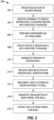
- FIG. 2 illustrates a flowchart 200 of an example method for generating and outputting hollow model data according to an example described herein.
- This flowchart 200 provides a detailed example from the perspective of a computing system and software configured to receive and respond to user interaction, such as from visualization software operating on the visualization computer system 110. It will be understood, however, that these operations may be distributed among multiple computer systems or devices (including systems under the control or direction of user inputs).
- the visualization software may operate to receive a selection of a source region (operation 202), such as the selection of a segmented object or anatomical feature.
- the visualization software may operate to receive a command to create a region shell in the source region (operation 204) from the segmented object or anatomical feature.
- this region shell is created (operation 208) with the use of a binary voxel mask for a desired thickness t (e.g., a thickness value specified by the user or determined by the visualization software), including in some examples the use of supersampling upon the voxel mask (operation 206).
- the visualization software may operate to generate a preview of the region shell (operation 210) for output to the user in a user interface of the visualization software.
- the visualization software may further operate to receive user selections of region shell modifications within the user interface (operation 212), such as user selections for thickness, layer, and endpoint modifications of the shell, and to implement these modifications to the shell (operation 214).
- the visualization software operates to extrude and output a visualization for a mesh model of the shell (operation 216) and generate data for the mesh model of the shell (operation 218).
- This data for the mesh model is exported for further visualization in a computer aided design program, exported to a 3D printer for printing, or like uses for a 3D representation of the shell.
- Extrusion refers to a technique for creating a three-dimensional model from segmented 3D hollow anatomical structures of source medical imaging data and extending the profile (e.g., expanding the profile) of such hollow anatomical structures to a defined depth.
- the defined depth of the hollow model shell is referred to herein as the thickness.
- the result from the extrusion is a 3D visualization of the profile, which may be visualized and exported to a wireframe or mesh model as discussed above.
- the source medical imaging data provides a 3D voxel mask of the hollow anatomical structure from the one or more image volumes (e.g., the DICOM image data); in another example, the source imaging data provides contour data of the hollow anatomical structure from the one or more image volumes.
- the visualization software operates to extrude a shell of desired thickness, constrained by the voxel granularity, by dilating the original binary voxel mask and then removing the original voxel mask from the dilated result.
- the operations to extrude the shell may be performed using supersampling to allow an increased granularity of the shell thickness.
- supersampling may be performed upon voxels of a first resolution (e.g., voxels of a 1mm resolution) in order to generate a second, finer resolution for use in the extruded shell (e.g., voxels used in a layer thickness of .5mm).
- Trilinear or tricubic interpolation may be used to supersample the binary region mask in order to reduce aliasing artifacts in the resulting structure and yield a smoother surface model if one is ultimately extracted.
- binary masks for other anatomy may be (a) removed from the shell mask (if they are fixed), or (b) updated to exclude the shell (if they are not fixed).
- the created shell may be provided as a manipulable region within the visualization software, and thus may be merged with other regions or edited with tools provided by the visualization software for other regions.
- the generation of the region shell may be performed within the visualization software as a specialized segmentation operation.
- the following algorithm may be performed to generate a hollow object shell from mask M :
- a hollow object shell may be generated within the visualization software from a centerline-enumerated set of an inner and an outer contour of an anatomical structure, such as from contours obtained from cross-sectioning of a hollow segmented hollow anatomical structure.
- a surface model of the hollow object shell may be extracted from the inner and outer counters of an identified, segmented hollow anatomical structure. The extent of the extracted surface model may be defined from a dilation of the inner contour or from anatomical information within the three-dimensional medical imaging data. Use of such contour information may be useful for generating a realistic representation of the structure, while also permitting automatic endpoint clipping, multi-layered shells, and variable shell thickness, according to the techniques further discussed herein. Additionally, centerline-based editing within the visualization software may directly impact the quality of a resulting shell.
- This algorithm and the use of the method of flowchart 200 for generating and outputting hollow model data may be used to extract a shell region in the visualization software, and to produce a shell that envelops a target region prior to surface computation. This enables context to be maintained before the mesh/surface extraction step is performed, even as a user can continue to display the relevant region and segmented structures in the visualization software application.
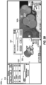
- FIG. 3A illustrates a graphical user interface 300a of a medical imaging visualization software program configured to select a segmentation mask for use in generating a hollow model according to an example.
- the graphical user interface 300a includes a listing 310 of anatomical segments, a segmentation layer 320 to visualize a segmented hollow object of an anatomical structure (as depicted, the interior structure of an aorta), a visualization 330 of the segmented hollow object, and an overlay 342a on a two-dimensional medical image 340a depicting a view of the surrounding anatomical structure (as illustrated, a radiology image that denotes the portion of the anatomical structure depicted in the visualization 330).
- the graphical user interface 300a depicts a series of further user interface options to be performed upon the segmentation layer 320, including a "Create Shell” menu option 322, in addition to options to show, delete, or modify aspects of the segmentation layer 320.
- the "Create Shell” menu option 322 may operate as a user-selectable option to create the region shell and to initiate the region shell creation operations discussed above with reference to FIG. 2 .
- FIG. 3B illustrates a graphical user interface 300b of a medical imaging visualization software program configured to apply a segmentation mask for use in generating a hollow model according to an example.
- Features of the graphical user interface 300b include those discussed above for the graphical user interface 300a in FIG. 3A .
- the graphical user interface 300b depicts a scenario occurring after selection of the "Create Shell" menu option 322, to receive further user interaction.
- a user interface input 324 is presented to allow a user to define or modify a shell thickness.
- the user interface input 324 may include options to apply the defined thickness and to preview the results of the defined thickness. For example, these options may be used to implement operations 204 and 208 in FIG. 2 , to create and apply a region shell with a user-specified thickness, and operation 210 in FIG. 2 , to generate a preview of the region shell.
- FIG. 3C illustrates a graphical user interface 300c of a medical imaging visualization software program configured to produce an extruded shell region for use in generating a hollow model according to an example.
- Features of the graphical user interface 300c include those discussed above for the graphical user interfaces 300a, 300b in FIGS. 3A and 3B .
- the graphical user interface 300c depicts a scenario occurring after entry of the user interface input 324 from FIG. 3B .
- the hollow object space is used to produce a visualization 332 of the extruded shell region, which is accompanied by a characteristics output 328 of the hollow shell being depicted with the visualization 332.
- This provides an example of operations 210 and 214 in FIG. 2 , to generate a preview of the region shell and to implement modifications to the region shell.
- the listing 310 of anatomical segments is updated to include a shell segmentation layer 326 in addition to the hollow space represented by the segmentation layer 320.
- the graphical user interface 300c also provides an additional overlay 342b within the two-dimensional image 340c of the shell created for hollow structure, in addition to the overlay 342a of the hollow structure.
- the visualization software may provide a perspective of the shell relative to the two-dimensional image 340c and other depictions of anatomy.
- the visualization 332 depicts an extracted shell region that envelops the target region prior to surface computation, while maintaining the context and flexibility of working with regions and segmented layers before a mesh/surface extraction step is applied.
- This shell region is extracted and displayed within the original data context so that it may be visualized and/or modified alongside the source scan data.
- a 3D and Multiplanar Reconstruction (MPR) preview of the shell within the original data allows the user to accept or modify the shell properties before extruding the new shell region. As a result, the shell may be extracted without topological issues or ambiguities arising from the source region.
- MPR Multiplanar Reconstruction
- FIG. 3D illustrates a graphical user interface 300d of a medical imaging visualization software program configured to visualize a shell region for use in generating a hollow model according to an example described herein.
- Features of the graphical user interface 300d include those discussed above for the graphical user interface 300a, 300b, 300c of FIGS. 3A , 3B , and 3C .
- the graphical user interface 300d depicts a scenario occurring after selection of a user interface input to remove the hollow structure layer (the segmentation layer 320) and to export the hollow shell (from the shell segmentation layer 326).
- the hollow region is extruded to produce a visualization 334 of an extruded shell region of the specified thickness, while still presenting features of the shell region in the graphical user interface 300d.
- An overlay 342c of the shell region is depicted in the two-dimensional image 340d, with a hollow cavity area 342d being omitted in the two-dimensional image 340d.
- This provides an example of operation 216 in FIG. 2 , for generating a visualization of the mesh model for the shell.
- the graphical user interface 300d may provide an export option interface 352 to directly enable an .STL export of the visualization data.
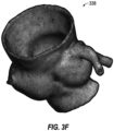
- FIGS. 3E and 3F illustrate an enlarged graphical visualization 336 and a mesh model visualization 338 respectively for a hollow model produced as an output of a medical imaging visualization software program according to an example described herein.
- FIG. 3F provides an example of operation 218 in FIG. 2 , of data of a mesh model that is that is exported for a hollow shell.
- the mesh model may be exported from the graphical visualization 336 of the extruded shell region, for example, and generated into a CAD format.
- 3D hollow models also may be used for medical modelling and simulation.
- region shells may be defined not only for a physical delineation but also for a clinical justification, such as to define a margin region surrounding a tumor.
- the generation of the hollow model within may be used for modeling a variety of scenarios, conditions, and environments of human anatomy.
- FIGS. 3A , 3B , 3C , 3D , 3E , and 3F are provided with reference to the generation and visualization of a hollow model from one image volume.
- a hollow model may be generated and visualized from data among a plurality of image volumes.
- multiple image volumes (or series or phases) of three-dimensional imaging data may be used instead of a single volume to perform the generation of the region shell.
- the source region may be segmented in the multiple volumes, and the shell generation is propagated in each volume.
- the graphical user interface of the visualization software may include features to allow the selection and depiction of respective volumes for use in generating the hollow shell.
- the present techniques for generating a hollow model may be combined with automated features for clipping ends of a hollow model for a vascular tree structure. These techniques may utilize morphological information to assist a user in quickly trimming away distal tree endpoints of a previewed hollow model shell.
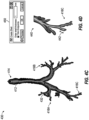
- FIGS. 4A, 4B , 4C, and 4D illustrate respective visualizations of a tubular tree structure of a hollow model in a medical imaging visualization interface configured to identify and implement trimming for endpoints of the tree structure according to an example.
- FIG. 4A depicts the illustration of a hollow model 410 generated from the techniques described herein, such as for a hollow model of an airway.
- the hollow model 410 may include a morphological tree branching outline 412 identified within the hollow model 410, with this branching outline 412 (a centerline) extending throughout the hollow model 410. These tree branches may stem to some or all portions of the hollow model 410.
- FIG. 4A further depicts the identification of a plurality of endpoints that are automatically detected at the ends of the branching outline 412, such as at endpoints in branches 414, 416A, 416B, 416C. Before trimming, these respective endpoints are closed due to the exterior definition of the hollow shell. However, the tubular structure may be opened for better visualization, phantom design, and for computed flow dynamic, and to enable proper output of 3D printing.
- FIG. 4B depicts the illustration of a hollow model 420 generated after trimming, according to one example.
- the branching outline 412 is depicted as extending throughout the hollow model 420, but with portions of the hollow model that have the region shell cut X mm before the centerline endpoints.
- the endpoint in branch 424 of the hollow model 420 may be trimmed to expose a large opening for the airway; whereas the endpoints in branches 426A, 426B, 426C of the hollow model 420 may be trimmed to expose small openings for the respective endpoints of the tree structure.
- FIG. 4C depicts an illustration of a hollow model 430, based on the depiction of the hollow model 410 in FIG. 4A prior to trimming, but with the hollow model 430 including modifications to the selection of the branches to be trimmed.
- the branch 416A is shown as being unselected (with a highlighted branch outline 432, such as may be depicted an alternate color or shading), whereas the outlines into the branches 416B, 416C remain selected.
- the selection (or unselection) of respective branches may be implemented by receiving user interface inputs to designate such branches (such as by a user clicking on a particular branch to control whether the endpoints of the particular branch will or will not be trimmed).
- a default option may apply trimming to all endpoints of a branch outline.
- a user may accept or reject trimming of respective endpoints, or trimming of certain endpoints may be automatically controlled based on the type of anatomical structure being modeled. For example, a user may not intend to trim a cardiac apex when creating a hollow model of heart chambers.
- FIG. 4D depicts a close-up illustration 440 of a portion of the branch 416C from the hollow model 410, 430 depicted in FIGS. 4A and 4C .
- This portion of the branch 416C is illustrated before clipping, with an illustration of a clipping portion 442 to be removed from the hollow model 410, 430.
- the clipping portion 442 corresponds to a selection value specified in a graphical user interface input 450, to "trim endpoints".
- the selections received in the graphical user interface input 450 may include a trim option (such as a check box whether to trim or not trim endpoints), and trim size (not shown, such as to trim X mm on centerline from selected endpoints).
- An amount of the shell thickness to trim from an endpoint may correspond to an automatically determined value; or, the amount of the shell thickness to trim from an end point may correspond to user-input values or inputs.
- the amount of the shell thickness to trim for a proximal endpoint may be different from a distal endpoint, or fixed default values may be used for proximal and distal endpoints respectively.
- the thickness or definition for the hollow model shell is modified with constrained region generation techniques, such as to prevent interference or overlap with other shells or anatomical structures.
- FIGS. 5A, 5B, and 5C illustrate respective visualizations 510, 520, 530 of a region shell constrained for neighboring structures according to an example.
- a hollow shell model is modified to prevent expansion in segmented region that conflicts with another region.
- FIG. 5A depicts the visualization 510 of a region shell generation where a first shell 512 of a hollow region 1 is partially contiguous with a second shell 514 of a hollow region 2.
- the contiguous region 515 conflicts, and growing the region shell of either the first shell 512 or the second shell 514 in a contiguous structure may destroy a previous segmented structure.
- FIG. 5B depicts the visualization 520 of a modification to the region shell generation technique, to adapt to the contiguous structure conflict of FIG. 5A .
- the visualization 520 is provided for a scenario where the first shell 522 and the second shell 524 are resized to remove the contiguous conflict.
- region 525 is adapted to reduce the size of the conflict in the region 525, by causing a change to the hollow shell to preserve the size of the hollow region 2 and the second shell 524, while reducing the size of the hollow region 1 to preserve the shell walls of the first shell 522.
- FIG. 5C depicts the visualization 530 of a modification to the region shell generation, to adapt to the contiguous structure conflict of FIG. 5A .
- the visualization 530 is provided for a scenario where a region 535 is adapted to be not contiguous, where a normal thickness of a shell 532 would conflict in part with a shell 534.
- the shell 532 is configured to establish a locally reduced thickness in the conflict area, while preserving the source of the hollow region 1. (The region source of the hollow region 2 and the shell 534 are not affected).
- constraints are used to generate or modify a shell, to ensure that certain structures are preserved, or to ensure that shell walls do not interfere with critical structures.
- a shell is created or modified to be "thinner” because the mass of the region is subtracted from the dilated portion, or subtracted directly from a shell. Consequently, constraints of a hollow structure and neighboring structures (and neighboring shells) are used to prevent any hollow model from conflicting with overlapping structures of interest.
- a user interface control such as a checkbox may be used to define a hollow model constraint (and preserve the selected region or anatomical structure from interference).
- This user interface control which may be provided from selecting a particular object that is constrained from a list of objects, may provide a constraint that a user can directly modify.
- a user interface control such as a checkbox can also display a status to a user to easily determine which layers or structures are to be preserved during model generation.
- the thickness or definition for a hollow model shell may be modified based on predefined modeling characteristics.
- a variable thickness for a shell wall of the airway structure may be determined and applied to a hollow model automatically or in response to user selection, depending on the type of branching or the anatomical structure being modeled.
- the use of wall segmentation with variable thickness may be used to produce more realistic models for large vessel models or organ characteristics.
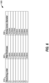
- FIG. 6 illustrates a chart 600 of respective values for defining variable thickness of a region shell of an airway structure according to an example described herein.
- the thickness of a hollow model may be designed to resemble an airway wall shell that varies with airway branch generation characteristics.
- the chart 600 depicted in FIG. 6 provides an illustration of a comparison of wall thickness 620 in comparison to lumen diameter 630.
- the typical wall thickness related to the branching order of the airway branch, with the branching order, follows Weibel's model.
- the computation of the variable wall thickness for the airways may be based upon a pre-computed branching order or the airway branch. In another example, the variable wall thickness may be based upon the local lumen diameter.
- variable wall thickness for a lung bronchial structure are indicated in Montaudon et al., Assessment of bronchial wall thickness and lumen diameter in human adults using multi-detector computed tomography: comparison with theoretical models, Journal of Anatomy (2007), Vol. 211, pp. 577-588 . Accordingly, the thickness of a hollow airway model may be adjusted based on these and like findings.
- the thickness of a hollow model may be designed to resemble a blood vessel, such as an artery or vein structure (e.g., coronaries).
- a blood vessel such as an artery or vein structure (e.g., coronaries).
- a simple way to compute the variable wall thickness changing with the local vessel diameter is to apply existing data from the human anatomy.
- Customized models may also be generated from a sample of vessel diameter and vessel wall thickness and fitting a similar power law using parametric curve fitting techniques.
- respective wall thickness values for an artery or vein may be defined based on a linear log-log relationship between arterial wall thickness (mm) and inner diameter (mm). Additional examples of variable wall thickness in arteries and veins are indicated in Guo et al., Diameter-dependent axial prestretch of porcine coronary arteries and veins, Journal of Applied Physiology, Vol. 112 no. 6, pp. 982-989 .
- variable thickness modeling technique also may be used to create a shell wall that is modeled to become thinner as the shell extends from an anatomical point of interest or to provide a shell of smoothly varying thickness.
- a modeled result may be produced from a modeling paradigm that starts with thicker elements, and becomes thinner moving in a distal/lateral direction.
- Such modeling may provide an enhancement to forms of simple generic wall segmentation, to assist generation of realistic models for large vessel models.
- variable thickness modeling techniques may be applicable to modeling of spaces for a segmented tubular structure such as arteries, veins, airways, bile ducts, or ureters, or for cavity organs such as a gallbladder, urinary bladder, stomach, heart, or colon.
- the hollow model shell may be generated to include a plurality of layers that correspond to identified anatomical features.
- FIGS. 7A and 7B illustrate a depiction of layers of an anatomical structure used for defining variable thicknesses of a multi-layer region shell according to an example.
- the simulation of biomimetic structures may include composite multi-layer structures.
- FIG. 7A depicts a cut-out view of an artery wall structure, including a first layer 702 (e.g., corresponding to an adventitial layer), a second layer 704 (e.g., corresponding to a medial layer), and a third layer 706 (e.g., corresponding to an intimal layer).
- FIG. 7B depicts a cross-section view 720 of the artery wall structure, including the varying thicknesses for the first layer 702, second layer 704, and third layer 706 (indicated in the display of the thickness values 730 at a point of the vessel).
- varying thicknesses may be produced from data of high resolution imaging modalities (e.g., CT scanners) that provide a high resolution export of data. Accordingly, imaging data may be used to model or provide a direct source of the thickness for a particular modeling of an anatomical structure.
- FIG. 8 illustrates a graphical depiction 800 of multi-layer region shell generated from the artery wall structure of FIGS. 7A and 7B according to an example.
- the graphical depiction 800 includes an interior lumen 810 (the hollow space) surrounded by a third layer 802, a second layer 804, and a first layer 806.
- the graphical depiction may provide a representation of an approximation of the thickness presented at various portions of the artery wall structure, such as determined with the imaging techniques used to produce the cross-section view 720 in FIG. 7B .
- the multiple layers (e.g., two or more layers) of an anatomical structure may be roughly defined using given ratios of thickness. These ratios and definitions may be adjusted and edited by a user in the graphical user interface as respective layers, or in response to automatic algorithms to match the anatomy as it appears in a source medical image.
- the uses of a multilayer region shell may support a number of applications in bioprinting, realistic simulated vessels, airway modeling, and the like.
- the use of a multilayer region shell also provides a number of benefits for the control of 3D printing parts and metamaterial.
- the generation of the multiple layers such as with the use of a 2- or 3-layer region option, may allow the printing of each part/layer with specific material properties. For example, a first layer may be created in a 3D printer with a soft material whereas the outer layer might be created in the 3D printer with a rigid material, to more correctly simulate the properties of the vessel or organ.
- FIG. 9 illustrates a flowchart 900 of a method for implementing region shell enhancements according to an example described herein.
- This flowchart 900 depicts the sequential application of the enhancements discussed above with reference to FIGS. 4A to 8 .
- additional or fewer enhancements may be provided in such a method, and that such enhancements may be optional or user-controlled.
- the flowchart 900 initially depicts an evaluation of whether to apply a region shell growing option (decision 902). If this option is selected or indicated, the visualization software may receive a user or automated selection of a shell growing option, and implement the selection or indication (operation 912). For example, this may include implementation of the operations described above with reference to FIGS. 5A, 5B, and 5C , including the generation or modification of region shells based on contiguous structure conflicts and whether to apply shell growing options into otherwise overlapping spaces.
- the flowchart 900 further depicts an evaluation of whether to apply a variable layer thickness option (decision 904). If this option is selected or indicated, the visualization software may receive a user or automated selection of a variable thickness for the hollow model, and implement the selection or indication (operation 914). For example, this may include implementation of the operations described above with reference to FIG. 6 , including the use of variable thickness values for a shell that is applied to model thicknesses of known anatomical features.
- the flowchart 900 further depicts an evaluation of whether to apply a variable layer thickness option (decision 906). If this option is selected or indicated, the visualization software may receive a user or automated selection of a number of layers and thickness values for each of the layers for the hollow model, and implement the selection or indication (operation 916). For example, this may include implementation of the operations described above with reference to FIGS. 7A, 7B, and 8 , including the definition of 2, 3, or more layers into a shell, and the generation of associated visualizations of such layers.
- the flowchart 900 further depicts an evaluation of whether to apply endpoint trimming (decision 908). If this option is selected or indicated, the visualization software may receive a user or automated selection of endpoints in a tree structure of the model to preserve or to manually trim, and a user or automated selection of trim distance and the amount of data to trim, and implement the selections or indications (operation 918). For example, this may include implementation of the trimming operations described above with reference to FIGS. 4A, 4B , 4C, and 4D , including the processing of user input received in a graphical user interface to select or de-select certain branches of a tree, and trimming the endpoints of selected branches of the tree to defined dimensions.
- a modified region shell may be produced (operation 920).
- This modified region shell may be generated for output as CAD-format data, or may be modeled further in an imaging visualization software application.
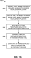
- FIG. 10A illustrates a flowchart 1000 of a method for generating hollow object model data according to the claimed invention.
- This flowchart 1000 provides a high-level depictions of operations used to generate the hollow object model data, but it will be understood that additional operations (including the integration of the operations from flowchart 900) may be optionally implemented into the depicted flow.
- the operations depicted in the flowchart 1000 include the generation of a voxel mask in a 3D space (operation 1002), from segmentation of a hollow object in a 3D space of one or more visualized images, provided in a medical imaging visualization application.
- a shell of desired thickness is extruded around the voxel mask (operation 1004), as this shell is generated within the 3D space that includes the contextual information of the medical image volume(s).
- Modifications may be received and applied to the extruded shell (operation 1006), such as may occur in the medical imaging visualization application with user input of thickness modifications, the addition of multiple layers, or endpoint trimming (e.g., as depicted in the enhancement operations from the flowchart 900 of FIG. 9 ).
- a computed surface representation of the modified extruded shell is generated (operation 1008).
- Data of the modified extruded shell (such as a mesh model) is then be exported to other visualization or 3D printing applications (operation 1010), in addition to output directly within the medical imaging visualization application.
- FIG. 10B illustrates a similar flowchart 1050 of an alternative method for generating hollow object model data, not forming part of the claimed invention.
- FIG. 10B provides details of this method with use of contour-based surface model extraction.
- the flowchart 1050 provides a high-level depictions of operations used to generate the hollow object model data, but it will be understood that additional operations (including the integration of the operations from flowchart 900) may be optionally implemented into the depicted flow.
- the operations depicted in the flowchart 1050 include the identification of an inner contour and an outer contour from segmented hollow anatomical structure (operation 1052), such as from segmentation of a hollow object in a 3D space of one or more visualized images, within a medical imaging visualization application.
- a surface model is extracted from this inner and outer contour (operation 1058), based on one or more techniques which use the contextual information from the medical image volume(s).
- the technique for extracting the surface model involves definition of the extent of the surface model using a dilation of an inner contour of the segmented hollow anatomical structure (operation 1054).
- the technique for extracting the surface model involves definition of the extent of the surface model using the anatomical information directly within the 3D medical imaging data (operation 1056).
- modifications may be received and applied to the extracted surface model, such as may occur in the medical imaging visualization application with user input of thickness modifications, the addition of multiple layers, or endpoint trimming (e.g., as depicted in the enhancement operations from the flowchart 900 of FIG. 9 ).
- a computed visualization of the surface model is generated (operation 1060).
- Data of the modified extruded shell (such as a mesh model) can then be exported to other visualization or 3D printing applications (operation 1062), in addition to output directly within the medical imaging visualization application.
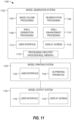
- FIG. 11 illustrates a block diagram 1100 of components used in respective systems to generate, output, and print model data for a hollow object according to an example described herein.
- the systems may include: a model generation system 1102 configured to generate and modify the hollow model data using the techniques described herein; a model printing system 1120 configured to generate a physical output (e.g., a 3D print) of the hollow model data using the techniques described herein; and a model output system 1130 configured to generate a virtual output (e.g., a computer display) of the hollow model data using the techniques described herein.
- a model generation system 1102 configured to generate and modify the hollow model data using the techniques described herein
- a model printing system 1120 configured to generate a physical output (e.g., a 3D print) of the hollow model data using the techniques described herein
- a model output system 1130 configured to generate a virtual output (e.g., a computer display) of the hollow model data using the techniques described herein.
- the model generation system 1102 may include processing circuitry 1116, a display screen 1114, a user interface 1112, and model processing components (including image volume processing 1104, segmentation processing 1106, shell generation processing 1108, and shell enhancement processing 1110).
- the model processing components 1104, 1106, 1108, 1110 and the user interface 1112 may be provided from specialized hardware operating independent from the processor and the memory; in other examples, the model processing components 1104, 1106, 1108, 1110 may be software-configured hardware that is implemented with use of the processor and the memory or other aspects of the processing circuitry 1116 (e.g., by instructions executed by the processor and the memory).
- the user interface 1112 and the display screen 1114 are used to engage the model processing components 1104, 1106, 1108, 1110 with use of the processing circuitry 1116, to generate and modify a hollow model using the techniques described herein.
- the model printing system 1120 may include a user interface 1122 and a 3D printing apparatus 1124, with the user interface 1122 used to control or affect operation of the 3D printing apparatus 1124.
- the 3D printing apparatus 1124 may be configured to receive, process, and output a 3D physical representation of the hollow model, based on hollow model data produced by the model generation system 1102.
- the model output system 1130 may include a user interface 1132 and a display screen 1134, with the user interface 1132 used to control or affect the display of a visualization of the hollow model via the display screen 1134 (including the output of CAD-based perspectives of the hollow model, as generated from the model generation system 1102).
- the features of the model output system 1130 may be integrated or combined with the features of the model generation system 1102 or the model printing system 1120.
- FIG. 12 is a block diagram illustrating an example computing system machine upon which any one or more of the methodologies herein discussed may be run.
- Computer system 1200 may be embodied as a computing device, providing operations of the components featured in the various figures, including components of the medical imaging system 108, visualization computer system 110, the model generation system 1102, the model printing system 1120, the model output system 1130, or as an execution platform for the operations in flowcharts 200, 900, or 1000 or the graphical user interfaces 300a, 300b, 300c, 300d, or any other processing, storage, or computing platform or component described or referred to herein.
- the machine operates as a standalone device or may be connected (e.g., networked) to other machines.
- the machine may operate in the capacity of either a server or a client machine in serverclient network environments, or it may act as a peer machine in peer-to-peer (or distributed) network environments.
- the computer system machine may be a personal computer (PC) that may or may not be portable (e.g., a notebook or a netbook), a tablet, a Personal Digital Assistant (PDA), a mobile telephone or smartphone, a web appliance, or any machine capable of executing instructions (sequential or otherwise) that specify actions to be taken by that machine.
- PC personal computer
- PDA Personal Digital Assistant
- a mobile telephone or smartphone e.g., a web appliance
- machine shall also be taken to include any collection of machines that individually or jointly execute a set (or multiple sets) of instructions to perform any one or more of the methodologies discussed herein.
- Example computer system 1200 includes a processor 1202 (e.g., a central processing unit (CPU), a graphics processing unit (GPU) or both), a main memory 1204 and a static memory 1206, which communicate with each other via an interconnect 1208 (e.g., a link, a bus, etc.).
- the computer system 1200 may further include a video display unit 1210, an alphanumeric input device 1212 (e.g., a keyboard), and a user interface (UI) navigation device 1214 (e.g., a mouse).
- the video display unit 1210, input device 1212 and UI navigation device 1214 are a touch screen display.
- the computer system 1200 may additionally include a storage device 1216 (e.g., a drive unit), a signal generation device 1218 (e.g., a speaker), a signal collection device 1232, and a network interface device 1220 (which may include or operably communicate with one or more antennas 1230, transceivers, or other wireless communications hardware), and one or more sensors 1226.
- a storage device 1216 e.g., a drive unit
- a signal generation device 1218 e.g., a speaker
- a signal collection device 1232 e.g., a microphone
- a network interface device 1220 which may include or operably communicate with one or more antennas 1230, transceivers, or other wireless communications hardware
- the storage device 1216 includes a machine-readable medium 1222 on which is stored one or more sets of data structures and instructions 1224 (e.g., software) embodying or utilized by any one or more of the methodologies or functions described herein.
- the instructions 1224 may also reside, completely or at least partially, within the main memory 1204, static memory 1206, and/or within the processor 1202 during execution thereof by the computer system 1200, with the main memory 1204, static memory 1206, and the processor 1202 also constituting machine-readable media.
- machine-readable medium 1222 is illustrated in an example embodiment to be a single medium, the term “machine-readable medium” may include a single medium or multiple media (e.g., a centralized or distributed database, and/or associated caches and servers) that store the one or more instructions 1224.
- the term “machine-readable medium” shall also be taken to include any tangible medium that is capable of storing, encoding or carrying instructions for execution by the machine and that cause the machine to perform any one or more of the methodologies of the present disclosure or that is capable of storing, encoding or carrying data structures utilized by or associated with such instructions.
- the term “machine-readable medium” shall accordingly be taken to include, but not be limited to, solid-state memories, optical media, and magnetic media.
- machine-readable media include non-volatile memory, including, by way of example, semiconductor memory devices (e.g., Electrically Programmable Read-Only Memory (EPROM), Electrically Erasable Programmable Read-Only Memory (EEPROM)) and flash memory devices; magnetic disks such as internal hard disks and removable disks; magneto-optical disks; and CD-ROM and DVD-ROM disks.
- semiconductor memory devices e.g., Electrically Programmable Read-Only Memory (EPROM), Electrically Erasable Programmable Read-Only Memory (EEPROM)
- flash memory devices e.g., Electrically Programmable Read-Only Memory (EPROM), Electrically Erasable Programmable Read-Only Memory (EEPROM)
- EPROM Electrically Programmable Read-Only Memory
- EEPROM Electrically Erasable Programmable Read-Only Memory
- flash memory devices e.g., electrically Erasable Programmable Read-Only Memory (EEPROM)
- flash memory devices e.g., Electrically Eras
- the instructions 1224 may further be transmitted or received over a communications network 1228 using a transmission medium via the network interface device 1220 utilizing any one of a number of well-known transfer protocols (e.g., HTTP).
- Examples of communication networks include a local area network (LAN), wide area network (WAN), the Internet, mobile telephone networks, Plain Old Telephone (POTS) networks, and wireless data networks (e.g., Wi-Fi, 3G, and 4G LTE/LTE-A or WiMAX networks).
- POTS Plain Old Telephone
- the term "transmission medium” shall be taken to include any intangible medium that is capable of storing, encoding, or carrying instructions for execution by the machine, and includes digital or analog communications signals or other intangible medium to facilitate communication of such software.
- a transmission medium is an embodiment of a machine readable medium.
- inventions described above may be implemented in one or a combination of hardware, firmware, and software. While some embodiments described herein illustrate only a single machine or device, the terms “system”, “machine”, or “device” shall also be taken to include any collection of machines or devices that individually or jointly execute a set (or multiple sets) of instructions to perform any one or more of the methodologies discussed herein.
- Examples, as described herein, may include, or may operate on, logic or a number of components, modules, or mechanisms.
- Such components may be tangible entities (e.g., hardware) capable of performing specified operations and may be configured or arranged in a certain manner.
- circuits may be arranged (e.g., internally or with respect to external entities such as other circuits) in a specified manner to implement such components.
- the whole or part of one or more computer systems (e.g., a standalone, client or server computer system) or one or more hardware processors may be configured by firmware or software (e.g., instructions, an application portion, or an application) that operates to perform specified operations.
- the software may reside on a machine readable medium.
- the software when executed by the underlying hardware, causes the hardware to perform the specified operations.
- such components may be a tangible entity that is physically constructed, specifically configured (e.g., hardwired), or temporarily (e.g., transitorily) configured (e.g., programmed) to operate in a specified manner or to perform part or all of any operation described herein.
- each of the components need not be instantiated at any one moment in time.
- the components comprise a general-purpose hardware processor configured using software
- the general-purpose hardware processor may be configured as respective different components at different times.
- Software may accordingly configure a hardware processor, for example, to constitute a particular components at one instance of time and to constitute a different component at a different instance of time.
- a client e.g., user-controlled
- a computing device having at least one processor and at least one memory, and the method implemented by electronic operations performed using the processor and the memory.
- the subject matter described herein may be embodied by a method performed by a server device (e.g., a remote computer system or computerized service) for generating a hollow model from medical image data to support operations of a client visualization software application, the software application executed by a computing device having at least one processor and at least one memory, and the method implemented by electronic operations performed using the processor and the memory.
- a server device e.g., a remote computer system or computerized service
- the subject matter described herein may be embodied by a machine-readable medium, the machine-readable medium carrying instructions, which when executed by a machine having a hardware processor, causes the machine to perform operations of the client- or server-performed method(s).
- a hollow model generation system comprising: processing circuitry including at least one processor and at least one memory; a display screen; a user interface output with the display screen; and features to generate a hollow model via the user interface using the operations described herein.
- a hollow model output system comprising: processing circuitry including at least one processor and at least one memory; a display screen; a user interface output with the display screen; and features to output a visualization of a hollow model via the user interface using the operations described herein.
- a hollow model printing system comprising: processing circuitry including at least one processor and at least one memory; a 3D printing apparatus under the control of the processor and memory; a user interface to operate the 3D printing apparatus; and instructions executed with the processor and the memory to perform the 3D printing of a hollow model with the 3D printing apparatus, the hollow model being produced using the operations described herein.
Landscapes
- Engineering & Computer Science (AREA)
- Physics & Mathematics (AREA)
- Software Systems (AREA)
- Computer Graphics (AREA)
- General Physics & Mathematics (AREA)
- Theoretical Computer Science (AREA)
- Health & Medical Sciences (AREA)
- Geometry (AREA)
- Medical Informatics (AREA)
- Public Health (AREA)
- Computer Hardware Design (AREA)
- General Engineering & Computer Science (AREA)
- General Health & Medical Sciences (AREA)
- Epidemiology (AREA)
- Primary Health Care (AREA)
- Nuclear Medicine, Radiotherapy & Molecular Imaging (AREA)
- Data Mining & Analysis (AREA)
- Databases & Information Systems (AREA)
- Pathology (AREA)
- Biomedical Technology (AREA)
- Radiology & Medical Imaging (AREA)
- Radar, Positioning & Navigation (AREA)
- Remote Sensing (AREA)
- Architecture (AREA)
- Apparatus For Radiation Diagnosis (AREA)
- Magnetic Resonance Imaging Apparatus (AREA)
Claims (11)
- Ein Verfahren zum Erzeugen eines Hohlraummodells von einem medizinischen Bild (104), durchgeführt durch Vorgänge, die in einer Visualisierungsanwendung für medizinische Bildgebung einer Rechenvorrichtung ausgeführt werden, wobei die Rechenvorrichtung mindestens einen Prozessor und mindestens einen Speicher aufweist, wobei die Vorgänge in der Rechenvorrichtung Folgendes beinhalten:Erzeugen (1002) einer Voxelmaske von einem Innenraum einer segmentierten anatomischen Struktur, wobei die segmentierte anatomische Struktur von Daten für dreidimensionale medizinische Bildgebung, die der Visualisierungsanwendung für medizinische Bildgebung bereitgestellt werden, produziert wird;Extrudieren (1004), in der Visualisierungsanwendung für medizinische Bildgebung, einer Schalenmaske mit einer definierten Dicke von der Voxelmaske,wobei das Extrudieren (1004) der Schalenmaske mit der definierten Dicke das Erzeugen einer dilatierten Voxelmaske aus der Voxelmaske und das Entfernen der Voxelmaske aus der dilatierten Voxelmaske umfasst,wobei die Schalenmaske modifiziert wird, um zu verhindern, dass die Schalenmaske eine andere, überlappende anatomische Struktur, die in der Visualisierungsanwendung für medizinische Bildgebung verwendet wird, überschneidet,wobei die Schalenmaske modifiziert wird, um eine binäre Voxelmaske der anderen anatomischen Struktur zu entfernen, falls die andere anatomische Struktur eine Struktur von Interesse ist, undwobei die binäre Voxelmaske der anderen anatomischen Struktur aktualisiert wird, um die Schalenmaske auszuschließen, falls die andere anatomische Struktur keine Struktur von Interesse ist;Erzeugen (1008) einer Visualisierung der extrudierten Schalenmaske, wobei die Visualisierung der extrudierten Schalenmaske zur Anzeige mit einer graphischen Benutzerschnittstelle der Visualisierungsanwendung für medizinische Bildgebung angepasst ist;Exportieren (1010) von Daten, die die extrudierte Schalenmaske darstellen, aus der Visualisierungsanwendung für medizinische Bildgebung,wobei die exportierten Daten ein Netzmodell der Schalenmaske definieren; undwobei die Visualisierung der extrudierten Schalenmaske, die auf der graphischen Benutzerschnittstelle der Visualisierungsanwendung für medizinische Bildgebung angezeigt wird, von dem Netzmodell der Schalenmaske produziert wird.
- Verfahren gemäß Anspruch 1, wobei die Vorgänge Folgendes beinhalten:
Vorschauen der Schalenmaske auf der graphischen Benutzerschnittstelle der Visualisierungsanwendung für medizinische Bildgebung, umfassend:Erzeugen einer ersten graphischen Vorschau der Schalenmaske auf einer ersten Anzeige auf der graphischen Benutzerschnittstelle, wobei die erste graphische Vorschau eine dreidimensionale Darstellung der Schalenmaske bereitstellt; undErzeugen einer zweiten graphischen Vorschau der Schalenmaske auf einer zweiten Anzeige auf der graphischen Benutzerschnittstelle, wobei die zweite graphische Vorschau eine Überlagerung der Schalenmaske auf ein medizinisches Quellbild bereitstellt,wobei das medizinische Quellbild eine zweidimensionale Darstellung eines dreidimensionalen Bilds ist, das unter Verwendung einer Computertomographie, Magnetresonanzbildgebung, 3D-Röntgenangiographie oder 3D-Ultraschallmodalität erfasst wird. - Verfahren gemäß Anspruch 1 oder Anspruch 2, wobei die Vorgänge Folgendes beinhalten:Empfangen, auf der graphischen Benutzerschnittstelle der Visualisierungsanwendung für medizinische Bildgebung, eines von dem Benutzer angegebenen Werts, um die definierte Dicke der Schalenmaske anzugeben; undAnzeigen einer dreidimensionalen Darstellung der Visualisierung der extrudierten Schalenmaske auf der graphischen Benutzerschnittstelle der Visualisierungsanwendung für medizinische Bildgebung.
- Verfahren gemäß einem der Ansprüche 1 bis 3, wobei die Vorgänge Folgendes beinhalten:Erzeugen der segmentierten anatomischen Struktur durch das Durchführen von Segmentierung an einem Bildvolumen, das die Daten für dreidimensionale medizinische Bildgebung bereitstellt; undEmpfangen einer Auswahl der segmentierten anatomischen Struktur auf der graphischen Benutzerschnittstelle der Visualisierungsanwendung für medizinische Bildgebung, wobei das Erzeugen der Voxelmaske von dem Innenraum der segmentierten anatomischen Struktur als Reaktion auf die Auswahl der segmentierten anatomischen Struktur durchgeführt wird.
- Verfahren gemäß Anspruch 1, wobei die dilatierte Voxelmaske durch Supersampling erzeugt wird, um eine feinere Auflösung für Voxel der dilatierten Voxelmaske als eine Auflösung der Voxelmaske zu erlangen.
- Verfahren gemäß einem der Ansprüche 1 bis 5, wobei die segmentierte anatomische Struktur eine aus Röhren bestehende Baumstruktur umfasst und die Vorgänge Folgendes beinhalten:
Trimmen von Endpunkten der aus Röhren bestehenden Baumstruktur durch Modifizieren ausgewählter Enden der aus Röhren bestehenden Baumstruktur in der Schalenmaske, wobei die aus Röhren bestehende Baumstruktur durch Folgendes modifiziert wird:Erzeugen eines Baums aus einer Vielzahl von Mittellinien der segmentierten anatomischen Struktur;Berechnen von Endpunkten des Baums aus der Vielzahl von Mittellinien; undEntfernen von Abschnitten der Schalenmaske, die sich innerhalb einer bestimmten Entfernung von den Endpunkten des Baums befinden. - Verfahren gemäß einem der Ansprüche 1 bis 6, wobei das Extrudieren der Schalenmaske mit der definierten Dicke für einen Abschnitt der Schalenmaske, der eine Dicke aufweist, die eine benachbarte anatomische Struktur beeinträchtigt, Folgendes umfasst:Verringern der Dicke des Abschnitts der Schalenmaske; oderVerringern des Innenraums der segmentierten anatomischen Struktur, um die Dicke des Abschnitts der Schalenmaske beizubehalten.
- Verfahren gemäß einem der Ansprüche 1 bis 7, wobei das Extrudieren der Schalenmaske mit der definierten Dicke das Definieren einer Vielzahl von Schichten in der Schalenmaske umfasst und
wobei die Dicken jeweiliger Schichten der Vielzahl von Schichten in der Schalenmaske aus jeweiligen von dem Benutzer angegebenen Werten oder von dem System bestimmten Werten, die der segmentierten anatomischen Struktur entsprechen, festgelegt werden. - Verfahren gemäß einem der Ansprüche 1 bis 8, wobei die definierte Dicke innerhalb der Schalenmaske variabel ist, um eine Vielzahl von Dicken zu umfassen, und
wobei die Vielzahl von Dicken aus definierten anatomischen Verhältnissen von Dicken anatomischer Wände und Innendurchmesserwerten der segmentierten anatomischen Struktur bestimmt wird. - Mindestens ein maschinenlesbares Medium, das Anweisungen trägt, die, wenn sie von einem Rechensystem ausgeführt werden, das Rechensystem veranlassen, das Verfahren gemäß einem der Ansprüche 1 bis 9 durchzuführen.
- Ein System, das Folgendes beinhaltet:
ein Verarbeitungssystem (110, 1200) für medizinische Bildgebung, das programmiert ist, um das Verfahren gemäß einem der Ansprüche 1 bis 9 zu vollziehen.
Applications Claiming Priority (1)
| Application Number | Priority Date | Filing Date | Title |
|---|---|---|---|
| US15/080,246 US9824492B2 (en) | 2016-03-24 | 2016-03-24 | Hollow object model visualization in medical images |
Publications (2)
| Publication Number | Publication Date |
|---|---|
| EP3223246A1 EP3223246A1 (de) | 2017-09-27 |
| EP3223246B1 true EP3223246B1 (de) | 2024-03-27 |
Family
ID=58464142
Family Applications (1)
| Application Number | Title | Priority Date | Filing Date |
|---|---|---|---|
| EP17160713.8A Active EP3223246B1 (de) | 2016-03-24 | 2017-03-14 | Hohlkörperobjektmodellgenerierung aus einem medizinischen bild |
Country Status (2)
| Country | Link |
|---|---|
| US (1) | US9824492B2 (de) |
| EP (1) | EP3223246B1 (de) |
Families Citing this family (19)
| Publication number | Priority date | Publication date | Assignee | Title |
|---|---|---|---|---|
| CN108140264B (zh) * | 2015-09-26 | 2022-06-28 | 波士顿科学医学有限公司 | 可调深度的解剖外壳编辑 |
| EP3353753B1 (de) | 2015-09-26 | 2025-03-19 | Boston Scientific Scimed Inc. | Systeme und verfahren zur anatomischen schalenbearbeitung |
| DE102016200131A1 (de) * | 2016-01-08 | 2016-04-07 | Rz-Medizintechnik Gmbh | Verfahren zum Herstellen eines chirurgischen Instruments |
| DE112016007331T5 (de) * | 2016-10-11 | 2019-08-01 | Hewlett-Packard Development Company, L.P. | Erzeugen von daten für ein dreidimensionales (3d) druckbares objekt |
| WO2018071041A1 (en) * | 2016-10-14 | 2018-04-19 | Hewlett-Packard Development Company, L.P. | Rebuilding three-dimensional models to provide simplified three-dimensional models |
| WO2018086000A1 (en) * | 2016-11-09 | 2018-05-17 | Edan Instruments, Inc. | Systems and methods for ultrasound imaging |
| US10930078B1 (en) | 2017-11-01 | 2021-02-23 | Bentley Systems, Incorporated | Techniques for improving perception of projections of subsurface features on a terrain surface in augmented reality |
| US10489943B2 (en) | 2018-02-28 | 2019-11-26 | General Electric Company | System and method for sparse image reconstruction |
| JP7401540B2 (ja) * | 2018-11-09 | 2023-12-19 | バイダ ダイアグノスティクス,インコーポレイティド | 管状構造の切断面表示 |
| CN109727307B (zh) * | 2018-12-29 | 2023-08-22 | 上海联影医疗科技股份有限公司 | 一种表面网格切割方法、装置及计算机可读存储介质 |
| GB2581957B (en) * | 2019-02-20 | 2022-11-09 | Imperial College Innovations Ltd | Image processing to determine object thickness |
| EP3712855B1 (de) * | 2019-03-21 | 2026-01-07 | Siemens Healthineers AG | Visualisierung von medizinischen bilddaten |
| USD1035671S1 (en) * | 2019-12-19 | 2024-07-16 | GE Precision Healthcare LLC | Display panel with a graphical user interface for a magnetic resonance imaging apparatus |
| WO2021207289A1 (en) | 2020-04-07 | 2021-10-14 | Vida Diagnostics, Inc. | Subject specific coordinatization and virtual navigation systems and methods |
| US12266111B2 (en) | 2020-11-27 | 2025-04-01 | Vida Diagnostics, Inc. | Visualization of sub-pleural regions |
| US11776173B2 (en) * | 2021-05-04 | 2023-10-03 | GE Precision Healthcare LLC | Generating reformatted views of a three-dimensional anatomy scan using deep-learning estimated scan prescription masks |
| USD1048047S1 (en) * | 2021-11-29 | 2024-10-22 | Stratasys Ltd. | Display screen or portion thereof with graphical user interface |
| US12333659B2 (en) * | 2022-03-07 | 2025-06-17 | Gustav Lo | Systems and methods for displaying layered augmented anatomical features |
| CN120070780B (zh) * | 2025-04-29 | 2025-07-25 | 上海众茂医疗科技有限公司 | 适用于医学教学的三维可视化方法、装置、设备及介质 |
Family Cites Families (12)
| Publication number | Priority date | Publication date | Assignee | Title |
|---|---|---|---|---|
| US7050876B1 (en) * | 2000-10-06 | 2006-05-23 | Phonak Ltd. | Manufacturing methods and systems for rapid production of hearing-aid shells |
| WO2009064715A1 (en) | 2007-11-14 | 2009-05-22 | Auckland Uniservices Limited | Method for multi-scale meshing of branching biological structures |
| GB201003065D0 (en) | 2010-02-23 | 2010-04-07 | Simpleware Ltd | Image processing method and method of three-dimensional printing incorporating the same |
| GB2478801B (en) | 2010-03-16 | 2012-05-30 | Organovo Inc | Multilayered vascular tubes |
| US8315812B2 (en) | 2010-08-12 | 2012-11-20 | Heartflow, Inc. | Method and system for patient-specific modeling of blood flow |
| US9141763B2 (en) | 2011-02-07 | 2015-09-22 | Siemens Aktiengesellschaft | Method and system for patient-specific computational modeling and simulation for coupled hemodynamic analysis of cerebral vessels |
| US20140031967A1 (en) * | 2012-07-30 | 2014-01-30 | 6598057 Manitoba Ltd. | Method and system for rapid prototyping of complex structures |
| DE102013220539A1 (de) | 2013-10-11 | 2015-04-16 | Siemens Aktiengesellschaft | Modifikation einer Hohlorgan-Repräsentation |
| US9390232B2 (en) | 2014-03-24 | 2016-07-12 | Heartflow, Inc. | Systems and methods for modeling changes in patient-specific blood vessel geometry and boundary conditions |
| EP2949350B1 (de) | 2014-05-29 | 2022-05-11 | Sabanci Üniversitesi | Netzwerk aus künstlichem, hohlem biologischen Gewebe und Verfahren zur Herstellung davon |
| JP6451234B2 (ja) * | 2014-11-12 | 2019-01-16 | セイコーエプソン株式会社 | 立体物造形装置、立体物造形装置の制御方法、立体物造形装置の制御プログラム |
| US10730241B2 (en) * | 2014-11-17 | 2020-08-04 | Autodesk, Inc. | Techniques for automatically placing escape holes during three-dimensional printing |
-
2016
- 2016-03-24 US US15/080,246 patent/US9824492B2/en active Active
-
2017
- 2017-03-14 EP EP17160713.8A patent/EP3223246B1/de active Active
Non-Patent Citations (2)
| Title |
|---|
| JENSE G J ED - HORMANN KAI ET AL: "VOXEL-BASED METHODS FOR CAD", COMPUTER-AIDED DESIGN, ELSEVIER PUBLISHERS BV., BARKING, GB, vol. 21, no. 8, 1 October 1989 (1989-10-01), pages 528 - 533, XP000088135, ISSN: 0010-4485, DOI: 10.1016/0010-4485(89)90061-4 * |
| MORAWSKI A M ET AL: "A semi-automated algorithm for quantification of vessel wall angiogenesis associated with early atherosclerosis using magnetic resonance imaging", PROCEEDINGS OF THE 25TH. ANNUAL INTERNATIONAL CONFERENCE OF THE IEEE ENGINEERING IN MEDICINE AND BIOLOGY SOCIETY. CANCUN, MEXICO, SEPT. 17 - 21, 2003; [ANNUAL INTERNATIONAL CONFERENCE OF THE IEEE ENGINEERING IN MEDICINE AND BIOLOGY SOCIETY. EMBS], NE, vol. 1, 17 September 2003 (2003-09-17), pages 743 - 746, XP010693435, ISBN: 978-0-7803-7789-9, DOI: 10.1109/IEMBS.2003.1279871 * |
Also Published As
| Publication number | Publication date |
|---|---|
| US20170278301A1 (en) | 2017-09-28 |
| US9824492B2 (en) | 2017-11-21 |
| EP3223246A1 (de) | 2017-09-27 |
Similar Documents
| Publication | Publication Date | Title |
|---|---|---|
| US9824492B2 (en) | Hollow object model visualization in medical images | |
| JP7324268B2 (ja) | 複雑なデータのリアルタイムレンダリングのためのシステムおよび方法 | |
| JP7605909B2 (ja) | 三次元印刷指向の画像区分化のための方法およびシステム | |
| Giannopoulos et al. | 3D printed ventricular septal defect patch: a primer for the 2015 Radiological Society of North America (RSNA) hands-on course in 3D printing | |
| US9830427B2 (en) | Method for intracranial aneurysm analysis and endovascular intervention planning | |
| JP6243535B2 (ja) | 解剖学的構造のモデルベースのセグメンテーション | |
| EP3545500B1 (de) | System und verfahren zur darstellung von komplexen daten in einer umgebung der virtuellen realität oder erweiterten realität | |
| US20060100502A1 (en) | Anatomical visualization and measurement system | |
| CN114387380B (zh) | 用于生成3d医学图像数据的基于计算机的可视化的方法 | |
| JP4394127B2 (ja) | 領域修正方法 | |
| Zhang | Virtual reality technology | |
| JP6813549B2 (ja) | 医療報告を生成するための方法及びシステム | |
| CN108597038B (zh) | 一种三维表面建模方法及装置、计算机存储介质 | |
| JP5100717B2 (ja) | 画像処理装置及び画像処理方法 | |
| HK1244343A1 (en) | Hollow object model visualization in medical images | |
| JP2021047905A (ja) | 医療報告を生成するための方法及びシステム | |
| JP2021168053A (ja) | 立体を形状の狭隘部で分割する画像処理方法、画像処理プログラム、及び画像処理装置 | |
| Guachi et al. | 3D printing of prototypes starting from medical imaging: A liver case study | |
| Zhao et al. | A frame of 3D printing data generation method extracted from CT data | |
| JP2013013744A (ja) | 画像処理装置及び画像処理方法 | |
| Andersson et al. | Digital 3D Facial Reconstruction Based on Computed Tomography | |
| Nelson et al. | Solid object visualization of 3D ultrasound data | |
| Dotremont | From medical images to 3D model: processing and segmentation | |
| Tyler et al. | Visualizing MRI deep learning segmentation algorithms using 3D printing | |
| Dill et al. | 3D Printing from Cardiac CT Images |
Legal Events
| Date | Code | Title | Description |
|---|---|---|---|
| PUAI | Public reference made under article 153(3) epc to a published international application that has entered the european phase |
Free format text: ORIGINAL CODE: 0009012 |
|
| STAA | Information on the status of an ep patent application or granted ep patent |
Free format text: STATUS: THE APPLICATION HAS BEEN PUBLISHED |
|
| AK | Designated contracting states |
Kind code of ref document: A1 Designated state(s): AL AT BE BG CH CY CZ DE DK EE ES FI FR GB GR HR HU IE IS IT LI LT LU LV MC MK MT NL NO PL PT RO RS SE SI SK SM TR |
|
| AX | Request for extension of the european patent |
Extension state: BA ME |
|
| STAA | Information on the status of an ep patent application or granted ep patent |
Free format text: STATUS: REQUEST FOR EXAMINATION WAS MADE |
|
| 17P | Request for examination filed |
Effective date: 20180326 |
|
| RBV | Designated contracting states (corrected) |
Designated state(s): AL AT BE BG CH CY CZ DE DK EE ES FI FR GB GR HR HU IE IS IT LI LT LU LV MC MK MT NL NO PL PT RO RS SE SI SK SM TR |
|
| REG | Reference to a national code |
Ref country code: HK Ref legal event code: DE Ref document number: 1244343 Country of ref document: HK |
|
| STAA | Information on the status of an ep patent application or granted ep patent |
Free format text: STATUS: EXAMINATION IS IN PROGRESS |
|
| 17Q | First examination report despatched |
Effective date: 20200914 |
|
| RAP1 | Party data changed (applicant data changed or rights of an application transferred) |
Owner name: CANON MEDICAL SYSTEMS CORPORATION |
|
| GRAP | Despatch of communication of intention to grant a patent |
Free format text: ORIGINAL CODE: EPIDOSNIGR1 |
|
| STAA | Information on the status of an ep patent application or granted ep patent |
Free format text: STATUS: GRANT OF PATENT IS INTENDED |
|
| INTG | Intention to grant announced |
Effective date: 20231006 |
|
| GRAS | Grant fee paid |
Free format text: ORIGINAL CODE: EPIDOSNIGR3 |
|
| GRAA | (expected) grant |
Free format text: ORIGINAL CODE: 0009210 |
|
| STAA | Information on the status of an ep patent application or granted ep patent |
Free format text: STATUS: THE PATENT HAS BEEN GRANTED |
|
| AK | Designated contracting states |
Kind code of ref document: B1 Designated state(s): AL AT BE BG CH CY CZ DE DK EE ES FI FR GB GR HR HU IE IS IT LI LT LU LV MC MK MT NL NO PL PT RO RS SE SI SK SM TR |
|
| REG | Reference to a national code |
Ref country code: GB Ref legal event code: FG4D |
|
| REG | Reference to a national code |
Ref country code: CH Ref legal event code: EP |
|
| REG | Reference to a national code |
Ref country code: DE Ref legal event code: R096 Ref document number: 602017080328 Country of ref document: DE |
|
| REG | Reference to a national code |
Ref country code: IE Ref legal event code: FG4D |
|
| PG25 | Lapsed in a contracting state [announced via postgrant information from national office to epo] |
Ref country code: LT Free format text: LAPSE BECAUSE OF FAILURE TO SUBMIT A TRANSLATION OF THE DESCRIPTION OR TO PAY THE FEE WITHIN THE PRESCRIBED TIME-LIMIT Effective date: 20240327 |
|
| REG | Reference to a national code |
Ref country code: LT Ref legal event code: MG9D |
|
| PG25 | Lapsed in a contracting state [announced via postgrant information from national office to epo] |
Ref country code: GR Free format text: LAPSE BECAUSE OF FAILURE TO SUBMIT A TRANSLATION OF THE DESCRIPTION OR TO PAY THE FEE WITHIN THE PRESCRIBED TIME-LIMIT Effective date: 20240628 |
|
| PG25 | Lapsed in a contracting state [announced via postgrant information from national office to epo] |
Ref country code: HR Free format text: LAPSE BECAUSE OF FAILURE TO SUBMIT A TRANSLATION OF THE DESCRIPTION OR TO PAY THE FEE WITHIN THE PRESCRIBED TIME-LIMIT Effective date: 20240327 Ref country code: RS Free format text: LAPSE BECAUSE OF FAILURE TO SUBMIT A TRANSLATION OF THE DESCRIPTION OR TO PAY THE FEE WITHIN THE PRESCRIBED TIME-LIMIT Effective date: 20240627 |
|
| PG25 | Lapsed in a contracting state [announced via postgrant information from national office to epo] |
Ref country code: RS Free format text: LAPSE BECAUSE OF FAILURE TO SUBMIT A TRANSLATION OF THE DESCRIPTION OR TO PAY THE FEE WITHIN THE PRESCRIBED TIME-LIMIT Effective date: 20240627 Ref country code: NO Free format text: LAPSE BECAUSE OF FAILURE TO SUBMIT A TRANSLATION OF THE DESCRIPTION OR TO PAY THE FEE WITHIN THE PRESCRIBED TIME-LIMIT Effective date: 20240627 Ref country code: LT Free format text: LAPSE BECAUSE OF FAILURE TO SUBMIT A TRANSLATION OF THE DESCRIPTION OR TO PAY THE FEE WITHIN THE PRESCRIBED TIME-LIMIT Effective date: 20240327 Ref country code: HR Free format text: LAPSE BECAUSE OF FAILURE TO SUBMIT A TRANSLATION OF THE DESCRIPTION OR TO PAY THE FEE WITHIN THE PRESCRIBED TIME-LIMIT Effective date: 20240327 Ref country code: GR Free format text: LAPSE BECAUSE OF FAILURE TO SUBMIT A TRANSLATION OF THE DESCRIPTION OR TO PAY THE FEE WITHIN THE PRESCRIBED TIME-LIMIT Effective date: 20240628 Ref country code: FI Free format text: LAPSE BECAUSE OF FAILURE TO SUBMIT A TRANSLATION OF THE DESCRIPTION OR TO PAY THE FEE WITHIN THE PRESCRIBED TIME-LIMIT Effective date: 20240327 Ref country code: BG Free format text: LAPSE BECAUSE OF FAILURE TO SUBMIT A TRANSLATION OF THE DESCRIPTION OR TO PAY THE FEE WITHIN THE PRESCRIBED TIME-LIMIT Effective date: 20240327 |
|
| REG | Reference to a national code |
Ref country code: NL Ref legal event code: MP Effective date: 20240327 |
|
| PG25 | Lapsed in a contracting state [announced via postgrant information from national office to epo] |
Ref country code: SE Free format text: LAPSE BECAUSE OF FAILURE TO SUBMIT A TRANSLATION OF THE DESCRIPTION OR TO PAY THE FEE WITHIN THE PRESCRIBED TIME-LIMIT Effective date: 20240327 Ref country code: LV Free format text: LAPSE BECAUSE OF FAILURE TO SUBMIT A TRANSLATION OF THE DESCRIPTION OR TO PAY THE FEE WITHIN THE PRESCRIBED TIME-LIMIT Effective date: 20240327 |
|
| PG25 | Lapsed in a contracting state [announced via postgrant information from national office to epo] |
Ref country code: NL Free format text: LAPSE BECAUSE OF FAILURE TO SUBMIT A TRANSLATION OF THE DESCRIPTION OR TO PAY THE FEE WITHIN THE PRESCRIBED TIME-LIMIT Effective date: 20240327 |
|
| REG | Reference to a national code |
Ref country code: AT Ref legal event code: MK05 Ref document number: 1670639 Country of ref document: AT Kind code of ref document: T Effective date: 20240327 |
|
| PG25 | Lapsed in a contracting state [announced via postgrant information from national office to epo] |
Ref country code: NL Free format text: LAPSE BECAUSE OF FAILURE TO SUBMIT A TRANSLATION OF THE DESCRIPTION OR TO PAY THE FEE WITHIN THE PRESCRIBED TIME-LIMIT Effective date: 20240327 |
|
| PG25 | Lapsed in a contracting state [announced via postgrant information from national office to epo] |
Ref country code: IS Free format text: LAPSE BECAUSE OF FAILURE TO SUBMIT A TRANSLATION OF THE DESCRIPTION OR TO PAY THE FEE WITHIN THE PRESCRIBED TIME-LIMIT Effective date: 20240727 |
|
| REG | Reference to a national code |
Ref country code: HK Ref legal event code: WD Ref document number: 1244343 Country of ref document: HK |
|
| PG25 | Lapsed in a contracting state [announced via postgrant information from national office to epo] |
Ref country code: PT Free format text: LAPSE BECAUSE OF FAILURE TO SUBMIT A TRANSLATION OF THE DESCRIPTION OR TO PAY THE FEE WITHIN THE PRESCRIBED TIME-LIMIT Effective date: 20240729 Ref country code: SM Free format text: LAPSE BECAUSE OF FAILURE TO SUBMIT A TRANSLATION OF THE DESCRIPTION OR TO PAY THE FEE WITHIN THE PRESCRIBED TIME-LIMIT Effective date: 20240327 |
|
| PG25 | Lapsed in a contracting state [announced via postgrant information from national office to epo] |
Ref country code: ES Free format text: LAPSE BECAUSE OF FAILURE TO SUBMIT A TRANSLATION OF THE DESCRIPTION OR TO PAY THE FEE WITHIN THE PRESCRIBED TIME-LIMIT Effective date: 20240327 |
|
| PG25 | Lapsed in a contracting state [announced via postgrant information from national office to epo] |
Ref country code: CZ Free format text: LAPSE BECAUSE OF FAILURE TO SUBMIT A TRANSLATION OF THE DESCRIPTION OR TO PAY THE FEE WITHIN THE PRESCRIBED TIME-LIMIT Effective date: 20240327 Ref country code: EE Free format text: LAPSE BECAUSE OF FAILURE TO SUBMIT A TRANSLATION OF THE DESCRIPTION OR TO PAY THE FEE WITHIN THE PRESCRIBED TIME-LIMIT Effective date: 20240327 |
|
| PG25 | Lapsed in a contracting state [announced via postgrant information from national office to epo] |
Ref country code: AT Free format text: LAPSE BECAUSE OF FAILURE TO SUBMIT A TRANSLATION OF THE DESCRIPTION OR TO PAY THE FEE WITHIN THE PRESCRIBED TIME-LIMIT Effective date: 20240327 |
|
| PG25 | Lapsed in a contracting state [announced via postgrant information from national office to epo] |
Ref country code: PL Free format text: LAPSE BECAUSE OF FAILURE TO SUBMIT A TRANSLATION OF THE DESCRIPTION OR TO PAY THE FEE WITHIN THE PRESCRIBED TIME-LIMIT Effective date: 20240327 |
|
| PG25 | Lapsed in a contracting state [announced via postgrant information from national office to epo] |
Ref country code: SK Free format text: LAPSE BECAUSE OF FAILURE TO SUBMIT A TRANSLATION OF THE DESCRIPTION OR TO PAY THE FEE WITHIN THE PRESCRIBED TIME-LIMIT Effective date: 20240327 |
|
| PG25 | Lapsed in a contracting state [announced via postgrant information from national office to epo] |
Ref country code: SM Free format text: LAPSE BECAUSE OF FAILURE TO SUBMIT A TRANSLATION OF THE DESCRIPTION OR TO PAY THE FEE WITHIN THE PRESCRIBED TIME-LIMIT Effective date: 20240327 Ref country code: SK Free format text: LAPSE BECAUSE OF FAILURE TO SUBMIT A TRANSLATION OF THE DESCRIPTION OR TO PAY THE FEE WITHIN THE PRESCRIBED TIME-LIMIT Effective date: 20240327 Ref country code: RO Free format text: LAPSE BECAUSE OF FAILURE TO SUBMIT A TRANSLATION OF THE DESCRIPTION OR TO PAY THE FEE WITHIN THE PRESCRIBED TIME-LIMIT Effective date: 20240327 Ref country code: PT Free format text: LAPSE BECAUSE OF FAILURE TO SUBMIT A TRANSLATION OF THE DESCRIPTION OR TO PAY THE FEE WITHIN THE PRESCRIBED TIME-LIMIT Effective date: 20240729 Ref country code: PL Free format text: LAPSE BECAUSE OF FAILURE TO SUBMIT A TRANSLATION OF THE DESCRIPTION OR TO PAY THE FEE WITHIN THE PRESCRIBED TIME-LIMIT Effective date: 20240327 Ref country code: IS Free format text: LAPSE BECAUSE OF FAILURE TO SUBMIT A TRANSLATION OF THE DESCRIPTION OR TO PAY THE FEE WITHIN THE PRESCRIBED TIME-LIMIT Effective date: 20240727 Ref country code: ES Free format text: LAPSE BECAUSE OF FAILURE TO SUBMIT A TRANSLATION OF THE DESCRIPTION OR TO PAY THE FEE WITHIN THE PRESCRIBED TIME-LIMIT Effective date: 20240327 Ref country code: EE Free format text: LAPSE BECAUSE OF FAILURE TO SUBMIT A TRANSLATION OF THE DESCRIPTION OR TO PAY THE FEE WITHIN THE PRESCRIBED TIME-LIMIT Effective date: 20240327 Ref country code: CZ Free format text: LAPSE BECAUSE OF FAILURE TO SUBMIT A TRANSLATION OF THE DESCRIPTION OR TO PAY THE FEE WITHIN THE PRESCRIBED TIME-LIMIT Effective date: 20240327 Ref country code: AT Free format text: LAPSE BECAUSE OF FAILURE TO SUBMIT A TRANSLATION OF THE DESCRIPTION OR TO PAY THE FEE WITHIN THE PRESCRIBED TIME-LIMIT Effective date: 20240327 |
|
| PG25 | Lapsed in a contracting state [announced via postgrant information from national office to epo] |
Ref country code: IT Free format text: LAPSE BECAUSE OF FAILURE TO SUBMIT A TRANSLATION OF THE DESCRIPTION OR TO PAY THE FEE WITHIN THE PRESCRIBED TIME-LIMIT Effective date: 20240327 |
|
| PG25 | Lapsed in a contracting state [announced via postgrant information from national office to epo] |
Ref country code: IT Free format text: LAPSE BECAUSE OF FAILURE TO SUBMIT A TRANSLATION OF THE DESCRIPTION OR TO PAY THE FEE WITHIN THE PRESCRIBED TIME-LIMIT Effective date: 20240327 |
|
| REG | Reference to a national code |
Ref country code: DE Ref legal event code: R097 Ref document number: 602017080328 Country of ref document: DE |
|
| PG25 | Lapsed in a contracting state [announced via postgrant information from national office to epo] |
Ref country code: DK Free format text: LAPSE BECAUSE OF FAILURE TO SUBMIT A TRANSLATION OF THE DESCRIPTION OR TO PAY THE FEE WITHIN THE PRESCRIBED TIME-LIMIT Effective date: 20240327 |
|
| PG25 | Lapsed in a contracting state [announced via postgrant information from national office to epo] |
Ref country code: DK Free format text: LAPSE BECAUSE OF FAILURE TO SUBMIT A TRANSLATION OF THE DESCRIPTION OR TO PAY THE FEE WITHIN THE PRESCRIBED TIME-LIMIT Effective date: 20240327 |
|
| PLBE | No opposition filed within time limit |
Free format text: ORIGINAL CODE: 0009261 |
|
| STAA | Information on the status of an ep patent application or granted ep patent |
Free format text: STATUS: NO OPPOSITION FILED WITHIN TIME LIMIT |
|
| 26N | No opposition filed |
Effective date: 20250103 |
|
| PG25 | Lapsed in a contracting state [announced via postgrant information from national office to epo] |
Ref country code: SI Free format text: LAPSE BECAUSE OF FAILURE TO SUBMIT A TRANSLATION OF THE DESCRIPTION OR TO PAY THE FEE WITHIN THE PRESCRIBED TIME-LIMIT Effective date: 20240327 |
|
| PG25 | Lapsed in a contracting state [announced via postgrant information from national office to epo] |
Ref country code: MC Free format text: LAPSE BECAUSE OF FAILURE TO SUBMIT A TRANSLATION OF THE DESCRIPTION OR TO PAY THE FEE WITHIN THE PRESCRIBED TIME-LIMIT Effective date: 20240327 |
|
| REG | Reference to a national code |
Ref country code: CH Ref legal event code: H13 Free format text: ST27 STATUS EVENT CODE: U-0-0-H10-H13 (AS PROVIDED BY THE NATIONAL OFFICE) Effective date: 20251024 |
|
| PG25 | Lapsed in a contracting state [announced via postgrant information from national office to epo] |
Ref country code: LU Free format text: LAPSE BECAUSE OF NON-PAYMENT OF DUE FEES Effective date: 20250314 |
|
| GBPC | Gb: european patent ceased through non-payment of renewal fee |
Effective date: 20250314 |
|
| REG | Reference to a national code |
Ref country code: BE Ref legal event code: MM Effective date: 20250331 |
|
| PG25 | Lapsed in a contracting state [announced via postgrant information from national office to epo] |
Ref country code: GB Free format text: LAPSE BECAUSE OF NON-PAYMENT OF DUE FEES Effective date: 20250314 |
|
| PG25 | Lapsed in a contracting state [announced via postgrant information from national office to epo] |
Ref country code: FR Free format text: LAPSE BECAUSE OF NON-PAYMENT OF DUE FEES Effective date: 20250331 |
|
| PG25 | Lapsed in a contracting state [announced via postgrant information from national office to epo] |
Ref country code: BE Free format text: LAPSE BECAUSE OF NON-PAYMENT OF DUE FEES Effective date: 20250331 |
|
| PG25 | Lapsed in a contracting state [announced via postgrant information from national office to epo] |
Ref country code: CH Free format text: LAPSE BECAUSE OF NON-PAYMENT OF DUE FEES Effective date: 20250331 |
|
| PG25 | Lapsed in a contracting state [announced via postgrant information from national office to epo] |
Ref country code: IE Free format text: LAPSE BECAUSE OF NON-PAYMENT OF DUE FEES Effective date: 20250314 |
|
| PGFP | Annual fee paid to national office [announced via postgrant information from national office to epo] |
Ref country code: DE Payment date: 20260102 Year of fee payment: 10 |