EP3223233A1 - Image processing apparatus; image processing method; and vehicle control apparatus - Google Patents
Image processing apparatus; image processing method; and vehicle control apparatus Download PDFInfo
- Publication number
- EP3223233A1 EP3223233A1 EP17162563.5A EP17162563A EP3223233A1 EP 3223233 A1 EP3223233 A1 EP 3223233A1 EP 17162563 A EP17162563 A EP 17162563A EP 3223233 A1 EP3223233 A1 EP 3223233A1
- Authority
- EP
- European Patent Office
- Prior art keywords
- image
- operator
- data
- arithmetic operation
- intermediate data
- Prior art date
- Legal status (The legal status is an assumption and is not a legal conclusion. Google has not performed a legal analysis and makes no representation as to the accuracy of the status listed.)
- Withdrawn
Links
Images










Classifications
-
- G—PHYSICS
- G06—COMPUTING OR CALCULATING; COUNTING
- G06F—ELECTRIC DIGITAL DATA PROCESSING
- G06F9/00—Arrangements for program control, e.g. control units
- G06F9/06—Arrangements for program control, e.g. control units using stored programs, i.e. using an internal store of processing equipment to receive or retain programs
- G06F9/30—Arrangements for executing machine instructions, e.g. instruction decode
- G06F9/38—Concurrent instruction execution, e.g. pipeline or look ahead
- G06F9/3885—Concurrent instruction execution, e.g. pipeline or look ahead using a plurality of independent parallel functional units
-
- G—PHYSICS
- G06—COMPUTING OR CALCULATING; COUNTING
- G06T—IMAGE DATA PROCESSING OR GENERATION, IN GENERAL
- G06T1/00—General purpose image data processing
- G06T1/20—Processor architectures; Processor configuration, e.g. pipelining
-
- B—PERFORMING OPERATIONS; TRANSPORTING
- B60—VEHICLES IN GENERAL
- B60R—VEHICLES, VEHICLE FITTINGS, OR VEHICLE PARTS, NOT OTHERWISE PROVIDED FOR
- B60R16/00—Electric or fluid circuits specially adapted for vehicles and not otherwise provided for; Arrangement of elements of electric or fluid circuits specially adapted for vehicles and not otherwise provided for
- B60R16/02—Electric or fluid circuits specially adapted for vehicles and not otherwise provided for; Arrangement of elements of electric or fluid circuits specially adapted for vehicles and not otherwise provided for electric constitutive elements
-
- G—PHYSICS
- G05—CONTROLLING; REGULATING
- G05D—SYSTEMS FOR CONTROLLING OR REGULATING NON-ELECTRIC VARIABLES
- G05D1/00—Control of position, course, altitude or attitude of land, water, air or space vehicles, e.g. using automatic pilots
- G05D1/02—Control of position or course in two dimensions
- G05D1/021—Control of position or course in two dimensions specially adapted to land vehicles
- G05D1/0231—Control of position or course in two dimensions specially adapted to land vehicles using optical position detecting means
- G05D1/0246—Control of position or course in two dimensions specially adapted to land vehicles using optical position detecting means using a video camera in combination with image processing means
-
- G—PHYSICS
- G06—COMPUTING OR CALCULATING; COUNTING
- G06F—ELECTRIC DIGITAL DATA PROCESSING
- G06F9/00—Arrangements for program control, e.g. control units
- G06F9/06—Arrangements for program control, e.g. control units using stored programs, i.e. using an internal store of processing equipment to receive or retain programs
- G06F9/30—Arrangements for executing machine instructions, e.g. instruction decode
- G06F9/38—Concurrent instruction execution, e.g. pipeline or look ahead
- G06F9/3861—Recovery, e.g. branch miss-prediction, exception handling
- G06F9/3865—Recovery, e.g. branch miss-prediction, exception handling using deferred exception handling, e.g. exception flags
-
- G—PHYSICS
- G06—COMPUTING OR CALCULATING; COUNTING
- G06T—IMAGE DATA PROCESSING OR GENERATION, IN GENERAL
- G06T1/00—General purpose image data processing
- G06T1/60—Memory management
-
- H—ELECTRICITY
- H04—ELECTRIC COMMUNICATION TECHNIQUE
- H04N—PICTORIAL COMMUNICATION, e.g. TELEVISION
- H04N13/00—Stereoscopic video systems; Multi-view video systems; Details thereof
- H04N13/20—Image signal generators
- H04N13/204—Image signal generators using stereoscopic image cameras
- H04N13/207—Image signal generators using stereoscopic image cameras using a single two-dimensional [2D] image sensor
-
- H—ELECTRICITY
- H04—ELECTRIC COMMUNICATION TECHNIQUE
- H04N—PICTORIAL COMMUNICATION, e.g. TELEVISION
- H04N23/00—Cameras or camera modules comprising electronic image sensors; Control thereof
- H04N23/45—Cameras or camera modules comprising electronic image sensors; Control thereof for generating image signals from two or more image sensors being of different type or operating in different modes, e.g. with a CMOS sensor for moving images in combination with a charge-coupled device [CCD] for still images
-
- G—PHYSICS
- G06—COMPUTING OR CALCULATING; COUNTING
- G06T—IMAGE DATA PROCESSING OR GENERATION, IN GENERAL
- G06T2207/00—Indexing scheme for image analysis or image enhancement
- G06T2207/30—Subject of image; Context of image processing
- G06T2207/30248—Vehicle exterior or interior
- G06T2207/30252—Vehicle exterior; Vicinity of vehicle
Definitions
- the present invention relates to an image processing apparatus, an image processing method, and a vehicle control apparatus.
- Japanese Unexamined Patent Application Publication No. 2003-296096 discloses an arithmetic apparatus in which parallel processing is performed by pipeline processing. A plurality of arithmetic units are coupled in series in Japanese Unexamined Patent Application Publication No. 2003-296096 . Arithmetic operation data of a pre-stage arithmetic unit is outputted to a post-stage arithmetic unit.
- Japanese Unexamined Patent Application Publication No. 2002-182905 discloses an apparatus in which an arithmetic instruction is performed by a plurality of arithmetic elements.
- a register can be directly accessed from each of the arithmetic elements in Japanese Unexamined Patent Application Publication No. 2002-182905 .
- the register holds an arithmetic operation result of each arithmetic element.
- Each arithmetic unit may refer to a processing result of an arithmetic unit arranged prior to a pre-stage arithmetic unit.
- processing such as stereo processing and optical flow processing
- stereo processing different cameras handle an image of the same time.
- optical flow processing the same camera handles images of different times.
- a case is considered in which an arithmetic operation is performed by using pixel data of the two images.
- the pipeline processing is configured by a plurality of stages. There are many arithmetic operations in which amplification and selection are repeated in each stage.
- the amplification is an arithmetic operation to calculate many selection candidates.
- the selection is an arithmetic operation to select optimal data from among a plurality of selection candidates. Therefore, in processing such as the stereo processing and the optical flow processing, a huge number of selection candidates that are intermediately generated or a huge amount of data for generating the selection candidates is generated. Therefore, when employing a method of performing optimization calculation of a function result applied to the stereo processing and the optical flow processing on a one-dimensional path, a problem occurs in which the number of registers that hold intermediately-generated data increases.
- an image processing apparatus includes a plurality of pipelines arranged in parallel. Each of the pipelines has multi-stage processing units. Each of the processing units includes a first operator that performs a first arithmetic operation based on target pixel data corresponding to a target pixel of a first image and peripheral pixel data corresponding to peripheral pixels of the target pixel in a second image, a second operator which performs a second arithmetic operation based on first intermediate data based on an arithmetic operation result of the first operator and which calculates second intermediate data according to the first intermediate data of when the peripheral pixels are sequentially changed, a third operator which performs a third arithmetic operation based on first intermediate data and which calculates third intermediate data according to the first intermediate data of when the peripheral pixels are sequentially changed, a register that holds the second intermediate data of when the peripheral pixels are sequentially changed, and a delay element that delays the third intermediate data from the third operator.
- the program described above can be stored in various types of non-transitory computer readable media and supplied to a computer.
- the non-transitory computer readable media include various types of tangible storage media. Examples of the non-transitory computer readable media include a magnetic recording medium (for example, flexible disk, magnetic tape, and hard disk drive), a magneto-optical recording medium (for example, magneto-optical disk), a CD-ROM (Read Only Memory), a CD-R, a CD-R/W, and a semiconductor memory (for example, mask ROM, PROM (Programmable ROM), EPROM (Erasable PROM), flash ROM, and RAM (Random Access Memory)).
- the program may be supplied to a computer by various types of transitory computer readable media. Examples of the transitory computer readable media include an electrical signal, an optical signal, and an electromagnetic wave.
- the transitory computer readable media can supply the program to a computer through a wired communication path such as an electrical wire and an optical fiber or a
- An image processing apparatus is an image processing apparatus that performs pipeline processing on two images in parallel. That is, the image processing apparatus includes a plurality of pipelines arranged in parallel. Each pipeline includes multi-stage processing units. Data calculated by the processing unit is outputted to a post-stage processing unit. Thereby, the pipeline processing can be performed.
- the two images are a stereo image captured at the same time by a stereo camera having two cameras in a left-right direction or two images captured at different timings by one camera. It is possible to obtain distance information and motion information of a pattern by performing pattern matching in the stereo processing and the optical flow processing.
- pattern matching it is possible to use semi-global matching described in "Accurate and Efficient Stereo Processing by Semi-Global Matching and Mutual Information", Internet search: http://www.robotic.dlr.de/fileadmin/robotic/hirschmu/cvpr05hh.pdf.
- the image processing apparatus is used for a front monitoring system of a vehicle. It is possible to perform automatic control of a vehicle based on an image processing result of the image processing apparatus.
- Fig. 1 is a diagram showing a control configuration of a vehicle 1.
- the vehicle 1 has a camera 2, a camera ECU (Electronic Control Unit) 3, an EUC 4, a brake ECU 5, an accelerator ECU 6, and a steering ECU 7.
- the vehicle 1 includes not only a normal passenger car, but also a bus, a truck, and the like.
- the camera 2, the camera ECU 3, the EUC 4, the brake ECU 5, the accelerator ECU 6, and the steering ECU 7 are mounted on the vehicle 1. Further, the vehicle 1 is provided with an engine, a brake, a steering, wheels, and the like.
- Control units such as the camera ECU 3, the EUC 4, the brake ECU 5, the accelerator ECU 6, and the steering ECU 7 are realized by hardware such as a microcomputer and software such as a program loaded into a memory.
- the camera 2 is a stereo camera having two cameras installed in left and right positions of the vehicle 1.
- the camera 2 captures an image in front of the vehicle 1.
- a stereo image captured by two cameras of the camera 2 is outputted to the camera ECU 3.
- the camera ECU 3 has an image processing apparatus and performs image processing on the stereo image. Then, the camera ECU 3 outputs an image processing result to the ECU 4. For example, the camera ECU 3 calculates a distance from the vehicle 1 to an obstacle based on the image processing result.
- the ECU 4 has a control unit that controls the vehicle 1 based on the image processing result. For example, the ECU 4 outputs a control signal to control the brake ECU 5, the accelerator ECU 6, and the steering ECU 7.
- the brake ECU 5 controls a brake of the vehicle 1 according to the control signal.
- the accelerator ECU 6 controls an accelerator of the vehicle 1.
- the steering ECU 7 controls a steering of the vehicle 1.
- the ECU 4 outputs the control signal according to the image processing result, so that it is possible to automatically control the vehicle 1 by means of a system instead of a human being.
- Fig. 2 is a control block diagram showing a circuit configuration of the camera ECU 3.
- the camera ECU 3 has at least one CPU (Central Processing Unit) 22, a local memory 23, an external memory interface 24, an internal bus 25, at least one DSP (Digital Signal Processor) 26, a special hardware 27, an interface 28, a camera interface 29, and a camera interface 30.
- CPU Central Processing Unit
- DSP Digital Signal Processor
- the camera interfaces 29 30 are interfaces for inputting an image from the camera 2.
- an image captured by a left camera of the camera 2 is inputted into the camera ECU 3 through the camera interface 29.
- An image captured by a right camera of the camera 2 is inputted into the camera ECU 3 through the camera interface 30.
- the image captured by the left camera of the camera 2 is defined as a first image and the image captured by the right camera of the camera 2 is defined as a second image.
- the number of pixels in the first image is the same as that in the second image.
- the internal bus 25 has a bus line that couples the CPUs 22, the local memory 23, the external memory interface 24, the DSPs 26, the special hardware 27, the camera interface 29, and the camera interface 30 together.
- the interface 28 is an interface for inputting/outputting data from/to the ECU 4.
- the external memory interface 24 is an interface for inputting/outputting data from/to an external memory not shown in the drawings.
- the local memory 23 stores pixel data included in the first image and the second image.
- the CPUs 22 integrally control each of the local memory 23, the external memory interface 24, the internal bus 25, the DSPs 26, the special hardware 27, the interface 28, the camera interface 29, and the camera interface 30.
- the CPUs 22, the DSPs 26, and the special hardware 27 are hardware for implementing the image processing method according to the embodiment. That is, the image processing is performed in the CPUs 22, the DSPs 26, and the special hardware 27.
- the DSPs 26 and the special hardware 27 include a line memory which is an internal memory.
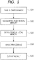
- Fig. 3 is a flowchart showing the image processing method in the camera ECU 3.
- the camera ECU 3 takes in a camera image (first image and second image) captured by the camera 2 through the camera interfaces 29 and 30 (S31) . Then, the camera ECU 3 develops the camera image in an external memory through the external memory interface 24 (S32).
- the camera ECU 3 develops pixel data developed in the external memory in the local memory 23 (S33).
- the camera ECU 3 performs image processing based on the pixel data stored in the local memory 23 (S34). Specifically, the image processing is performed when the CPUs 22, the DSPs 26, and the special hardware perform arithmetic operation processing on the pixel data.
- the camera ECU 3 outputs an image processing result to the ECU 4 and the like (S35). For example, the camera ECU 3 generates an output image based on the first and the second images captured by the camera 2 in step S34. The output image is formed from image data whose number of pixels is the same as that of the first and the second images. Then, the camera ECU 3 outputs the output image to the ECU 4 as an image processing result. The number of pixels may be thinned or cut as needed.
- the ECU 4 may control the brake ECU 5, the accelerator ECU 6, and the steering ECU 7 based on the image processing result. Thereby, the brake, the accelerator, and the steering are controlled. Therefore, it is possible to automatically control the vehicle 1. For example, a distance to an obstacle is obtained by the image processing apparatus. When it is determined that there is an obstacle nearby, the accelerator ECU 6 eases up on the accelerator and the brake ECU 5 applies the brake, so that the vehicle 1 decelerates. Alternatively, the steering ECU 7 controls the steering so as to avoid the obstacle.
- Fig. 4 shows a processing flow when the image processing in step S34 is performed by the general DSP 26 and the special hardware 27.
- the camera ECU 3 develops the pixel data, which is developed in the local memory, in an internal memory (S41).
- the internal memory is the line memory built in the DSP 26 or the special hardware 27.
- the internal memory stores image data used in the image processing. Then, the camera ECU 3 performs an arithmetic operation 1 on the pixel data stored in the line memory (S42) and internally holds an arithmetic operation result of the arithmetic operation 1 in a register (S43).
- the camera ECU 3 performs an arithmetic operation 2 by using the arithmetic operation result of the arithmetic operation 1 which is held in the register (S44) and internally holds an arithmetic operation result of the arithmetic operation 2 in the register (S45).
- the camera ECU 3 performs an arithmetic operation 3 by using the arithmetic operation result of the arithmetic operation 2 which is held in the register (S46) and internally holds an arithmetic operation result of the arithmetic operation 3 in the register (S47).
- Fig. 4 shows a flow in which the arithmetic operation and the internal holding are repeated three times.
- the arithmetic operations 1 to 3 are, for example, a multiply-accumulate (MAC) operation.
- Fig. 5 is a diagram for explaining pixels of the first image and the second image.
- Fig. 6 is a diagram for explaining the arithmetic operations 1 to 3. Specifically, Fig. 6 shows processing performed in one stage of a pipeline.
- images are shown as a first image R and a second image Ref.
- a horizontal direction (cross direction) of the first image R and the second image Ref is defined as an X direction, and a vertical direction (longitudinal direction) of these is defined as a Y direction.
- the first image R and the second image Ref are two-dimensional images having a total number of pixels D in the X direction (D is an integer greater than or equal to 2) and a total number of pixels H in the Y direction (H is an integer greater than or equal to 2).
- Pixel coordinates of the first image R and the second image Ref are represented as (x, y).
- a pixel of the pixel coordinates (x, y) in the first image R are represented as R(x, y).
- a pixel of the pixel coordinates (x+1, y) in the second image Ref are represented as Ref(x+1, y).
- x and y are arbitrary positive integers.
- Pixel data of each pixel of the first image R and the second image Ref is stored in the internal memory as described above.
- the pixel of the pixel coordinates (x, y) of the first image R is defined as a target pixel.
- a pixel located around the pixel coordinates (x, y) is defined as a peripheral pixel.
- the peripheral pixels are L pixels of Ref(x, y) to Ref(x+d, y).
- d is an arbitrary integer. It is designed so that the peripheral pixels include the same pixel coordinates as those of the target pixel.
- Fig. 6 shows a processing unit 250 that performs image processing on a target pixel of R(x, y). Specifically, Fig. 6 shows image processing for calculating output pixel data V(x, y) from pixel data of the target pixel R(x, y).
- the pixel data of the target pixel is defined as target pixel data
- the pixel data of the peripheral pixels is defined as peripheral pixel data.
- a first operator 251 performs an arithmetic operation by using the target pixel data and the peripheral pixel data.
- the target pixel data is pixel data corresponding to the target pixel R(x, y) of the first image R.
- the peripheral pixel data is pixel data of pixels located around the coordinates (x, y) of the second image Ref. Specifically, the peripheral pixel data is pixel data corresponding to peripheral pixels Ref(x, y) to Ref(x+d, y).
- the number of peripheral pixels is L, so that L first operators 251 are provided.
- L d + 1 (L and d are arbitrary positive integers).
- Each of the L first operators 251 performs arithmetic operation processing based on two pixel data. Thereby, L arithmetic operation results are obtained.
- the arithmetic operation performed by the first operator 251 corresponds to step S42 in Fig. 4 .
- Each of L registers 252 holds an arithmetic operation result.
- the arithmetic operation results held by the L registers 252 are represented as a data array Sc(x, y).
- the data array Sc(x, y) is formed from the L arithmetic operation results.
- the L is defined as the number of amplifications in the first operator 251.
- the number of amplifications L is the number of data generated for one target pixel R(x, y) in the first operator 251. For example, 128, 256, and the like are used as the number of amplifications L.
- Data holding by the register 252 corresponds to step S43 in Fig. 4 .
- the data array Sc(x, y) is generated by sequentially changing the peripheral pixels with respect to one target pixel R(x, y). More specifically, pixel data of L peripheral pixels are sequentially inputted into the first operator 251. Then, the data array Sc(x, y) is generated based on amplification data generated by the first operator 251.
- the data array Sc(x, y) is inputted into second operators 253a to 253d.
- second operators 253 are provided and the four second operators 253 are identified as the second operators 253a to 253d, respectively.
- data arrays S(x-1, y), S(x-1, y-1), S(x-2, y-1), and S(x+1, y-1) are inputted into the second operators 253a to 253d, respectively, from a line memory or another stage of pipeline processing.
- the second operators 253a to 253d perform a second arithmetic operation on the two inputted data arrays. Specifically, the second operators 253a to 253d update the data arrays S(x-1, y), S(x-1, y-1), S(x-2, y-1), and S(x+1, y-1) by using the data array Sc(x, y).
- the arithmetic operations performed by the second operators 253a to 253d correspond to step S44 in Fig. 4 .
- the data array Sc(x, y) and the data array S(x-1, y) are inputted into the second operator 253a. Then, the second operator 253a updates the data array S(x-1, y) by using the data array Sc(x, y). Similarly, the second operators 253b to 253d update S(x-1, y-1), S(x-2, y-1), and S(x+1, y-1) by using the data array Sc(x, y).
- the data arrays S(x-1, y), S(x-1, y-1), S(x-2, y-1), and S(x+1, y-1), which are generated by the second operators 253a to 253d, are defined as propagation data.
- the propagation data is calculated by using amplification data calculated from two pixels.
- the second operators 253a to 253d perform an arithmetic operation by using amplification data for a target pixel and a reference pixel.
- the coordinates of the target pixel of the second operator 253a is (x, y) and the coordinates of the reference pixel is (x-1, y).
- the coordinates of the target pixel of the second operator 253b is (x, y) and the coordinates of the reference pixel is (x-1, y-1).
- one amplification data is formed by L data arrays.
- the second operators 253a to 253d calculate the propagation data by using the amplification data for the target pixel and the amplification data for the reference pixel which is propagated from the target pixel in the X direction or the Y direction.
- the data arrays S(x-1, y), S(x-1, y-1), S(x-2, y-1), and S(x+1, y-1), which are updated by the second operators 253a to 253d, are held by registers 255a to 255d, respectively.
- Data holding by the registers 255a to 255d corresponds to step S45 in Fig. 4 .
- the registers 255a to 255d output the data arrays S(x-1, y), S(x-1, y-1), S(x-2, y-1), and S(x+1, y-1) to a third operator 256.
- the third operator 256 performs a third arithmetic operation on the data arrays S(x-1, y), S(x-1, y-1), S(x-2, y-1), and S(x+1, y-1). By doing so, the third operator 256 calculates a data array Ss(x, y).
- the arithmetic operation performed by the third operator 256 corresponds to step S46 in Fig. 4 .
- the data array Ss(x, y) generated by the third operator 256 is defined as selection candidate data.
- the selection candidate data is calculated by using the propagation data calculated from a plurality of pixels.
- the selection candidate data of the target pixel R(x, y) is calculated by using the propagation data calculated from four pixels.
- the third operator 256 outputs the data array Ss(x, y) to a register 257.
- the register 257 holds the data array Ss(x, y). The holding of the selection candidate data by the register 257 corresponds to step S47.
- the register 257 sequentially outputs the data array Ss(x, y) to the selector 258.
- the selector 258 selects optimal pixel data from the data array Ss(x, y) and outputs the pixel data as output pixel data Vx(x, y).
- the output pixel data Vx(x, y) is developed in the local memory 23.
- the data capacities of the data arrays S(x-1, y), S(x-1, y-1), S(x-2, y-1), and S(x+1, y-1), which are the propagation data tend to be large.
- the capacity of the propagation data is represented as L*D*H.
- Fig. 7 shows an execution flow in the processing shown in Fig. 6 .
- RD represents reading of pixel data from a line memory
- EX represents an arithmetic operation performed by an operator
- ST represents writing to a register.
- EX is performed twice each time. However, EX may be performed once or three times or more.
- One row in the horizontal direction corresponds to processing in each stage of a pipeline.
- the reading RD, the arithmetic operation EX, the arithmetic operation EX, and the writing ST are performed by using R(x+4, y) as the target pixel
- the reading RD, the arithmetic operation EX, the arithmetic operation EX, and the writing ST are performed by using R(x+3, y) as the target pixel. That is to say, an execution timing of the arithmetic operation EX is shifted once for each stage.
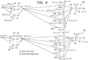
- a processing unit 250 of a first pipeline and a processing unit 350 of a second pipeline perform processing in parallel.
- the processing unit 250 and the processing unit 350 have the same configuration.
- a first operator 251, a register 252, a second operator 253, a register 255, a third operator 256, a register 257, and a selector 258 of the processing unit 250 respectively correspond to a first operator 351, a register 352, a second operator 353, a register 355, a third operator 356, a register 357, and a selector 358 of the processing unit 350.
- the processing of the processing unit 250 and the processing unit 350 is the same as the processing in Fig. 6 , so that the description thereof is omitted.
- the processing unit 250 of the first pipeline defines R(x, y) as the target pixel and the processing unit 350 of the second pipeline defines R(x, y+1) as the target pixel.
- the processing unit 250 of the first pipeline and the processing unit 350 of the second pipeline define pixels one pixel shifted from each other in the Y direction as the target pixels. Therefore, the peripheral pixels are also one pixel shifted from each other in the Y direction.
- Fig. 9 is shows an execution flow in the processing shown in Fig. 8 .
- RD represents reading of pixel data from a line memory
- EX represents an arithmetic operation performed by an operator
- ST represents writing to a register.
- EX is performed twice each time. However, EX may be performed once or three times or more.
- two pipelines perform pipeline processing in parallel. Specifically, the processing unit 250 of the first pipeline and the processing unit 350 of the second pipeline perform processing at the same time.
- the processing unit 250 of the first pipeline performs processing by defining R(x, y) as the target pixel
- the processing unit 350 of the second pipeline performs processing by defining R(x, y+1) as the target pixel.
- the target pixels are shifted from each other by one pixel. Therefore, as shown in Fig. 9 , the processing where R(x, y) is defined as the target pixel and the processing where R(x, y+1) is defined as the target pixel are performed at the same time.
- a timing (RD) when the processing unit 250 of the first pipeline reads pixel data of the target pixel R(x, y) and a timing (RD) when the processing unit 350 of the second pipeline reads pixel data of the target pixel R(x, y+1) are the same.
- Fig. 10 is a diagram for explaining a target pixel and peripheral pixels of two processing units of pipelines arranged in parallel.
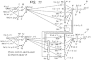
- Fig. 11 is a diagram showing an outline of a processing unit 50 of a first pipeline and a processing unit 150 of a second pipeline.
- the first pipeline and the second pipeline perform pipeline processing in parallel.
- the first pipeline and the second pipeline perform the pipeline processing by using pixels, which are one pixel shifted from each other in the Y direction, as target pixels.
- the first pipeline has multi-stage processing units to perform the pipeline processing.
- the second pipeline has multi-stage processing units to perform the pipeline processing.
- the processing unit included in the first pipeline uses a pixel, whose Y coordinate is y, as the target pixel.
- the processing unit included in the second pipeline uses a pixel, whose Y coordinate is y+1, as the target pixel.
- Fig. 11 shows a one-stage processing unit 50 in the first pipeline and a one-stage processing unit 150 in the second pipeline.
- the target pixel of the processing unit 50 is R(x, y) and the target pixel of the processing unit 150 is R(x-1, y+1).
- the processing unit 50 includes a first operator 51, a register 52, a second operator 53a, third operators 54b to 54d, a fourth operator 56, a selector 58.
- the processing unit 150 includes a first operator 151, a register 152, a second operator 153a, third operators 154b to 154d, a fourth operator 156, a register 157, and a selector 158, and delay elements 59b to 59d.
- the first operator 51 performs a first arithmetic operation by using target pixel data and peripheral pixel data.
- the target pixel data is pixel data corresponding to the target pixel R(x, y) of the first image R.
- the peripheral pixel data is pixel data of pixels located around the coordinates (x, y) of the second image Ref. Specifically, the peripheral pixel data is pixel data corresponding to peripheral pixels Ref(x, y) to Ref(x+d, y).
- the number of peripheral pixels is L, so that L first operators 51 are provided. Each of the L first operators 51 performs arithmetic operation processing based on two pixel data. Thereby, L arithmetic operation results are obtained.
- Each of L registers 52 holds an arithmetic operation result.
- the arithmetic operation results held by the L registers 52 are represented as a data array Sc(x, y).
- the data array Sc(x, y) is formed from the L arithmetic operation results.
- the L is defined as the number of amplifications in the first operator 51. Specifically, the number of amplifications L is the number of data generated for one target pixel R(x, y) in the first operator 51. For example, 128, 256, and the like are used as the number of amplifications L.
- the data array Sc(x, y) is generated by sequentially changing the peripheral pixels with respect to one target pixel R(x, y). More specifically, pixel data of L peripheral pixels are sequentially inputted into the operator 51. Then, the data array Sc(x, y) is generated based on amplification data generated by the first operator 51.
- the data array Sc(x, y) is inputted into the second operator 53a and the third operators 54b to 54d.
- three third operators 54 are provided and they are identified as the third operators 54b to 54d.
- the data arrays S(x-1, y), S(x-1, y-1), S(x-2, y-1), and S(x+1, y-1) are respectively inputted into the second operator 53a and the third operators 54b to 54d from a line memory or another stage of the pipeline processing.
- the second operator 53a and the third operators 54b to 54d perform a second arithmetic operation or a third arithmetic operation on two inputted data arrays. Specifically, the second operator 53a and the third operators 54b to 54d update the data arrays S(x-1, y), S(x-1, y-1), S(x-2, y-1), and S(x+1, y-1) by using the data array Sc(x, y).
- the data array Sc(x, y) and the data array S(x-1, y) are inputted into the second operator 53a. Then, the second operator 53a updates the data array S(x-1, y) by using the data array Sc(x, y). This is a second arithmetic operation.
- the third operators 54b to 54d update S(x-1, y-1), S(x-2, y-1), and S(x+1, y-1) by using the data array Sc(x, y).
- the data arrays S(x-1, y), S(x-1, y-1), S(x-2, y-1), and S(x+1, y-1), which are generated by the second operator 53a and the third operators 54b to 54d, are defined as propagation data.
- the data arrays S(x-1, y), S(x-1, y-1), S(x-2, y-1), and S(x+1, y-1) are inputted into the fourth operator 56.
- the third operators 54b to 54d perform the third arithmetic operation by using amplification data of two pixels. Specifically, the third operators 54b to 54d perform the third arithmetic operation by using amplification data of the target pixel and amplification data of the reference pixel.
- the target pixel of the third operator 54b is R(x, y) and the reference pixel of the third operator 54b is R(x-1, y-1).
- the target pixel of the third operator 54c is R(x, y) and the reference pixel of the third operator 54c is R(x-2, y-1).
- the target pixel of the third operator 54d is R(x, y) and the reference pixel of the third operator 54d is R(x+1, y-1).
- the fourth operator 56 performs a fourth arithmetic operation on the data arrays S(x-1, y), S(x-1, y-1), S(x-2, y-1), and S(x+1, y-1). By doing so, the fourth operator 56 calculates the data array Ss(x, y).
- the fourth arithmetic operation performed by the fourth operator 56 corresponds to step S46 in Fig. 4 .
- the data array Ss(x, y) generated by the fourth operator 56 is defined as selection candidate data.
- the selection candidate data is calculated by using propagation data calculated from a plurality of pixels.
- selection data of the target pixel R(x, y) is calculated by using propagation data calculated from four pixels.
- the fourth operator 56 outputs the data array Ss(x, y) to a register 57.
- the register 57 holds the data array Ss(x, y). Then, the register 57 sequentially outputs the data array Ss(x, y) to the selector 58.
- the selector 58 selects optimal pixel data from the data array Ss(x, y) and outputs the pixel data as output pixel data Vx(x, y). Specifically, the selector 58 selects the lowest cost data from a plurality of data included in the data array Ss(x, y).
- the first operator 151 performs a first arithmetic operation by using target pixel data and peripheral pixel data.
- the target pixel data is pixel data corresponding to the target pixel R(x+1, y+1) of the first image R.
- the peripheral pixel data is pixel data of pixels located around the coordinates (x+1, y+1) of the second image Ref. Specifically, the peripheral pixel data is pixel data corresponding to peripheral pixels Ref(x-1, y) to Ref(x-1+d, y).
- the number of peripheral pixels is L, so that L first operators 51 are provided. Each of the L first operators 51 performs arithmetic operation processing based on two pixel data. Thereby, L arithmetic operation results are obtained.
- Each of L registers 152 holds an arithmetic operation result.
- the arithmetic operation results held by the L registers 152 are represented as a data array Sc(x-1, y+1).
- the data array Sc(x-1, y+1) is formed from the L arithmetic operation results.
- the L is defined as the number of amplifications in the first operator 151.
- the number of amplifications L is the number of data generated for one target pixel R(x-1, y+1) in the first operator 151.
- the number of amplifications L has a value of 128, 256, and the like.
- the number of amplifications of the first operator 51 and the number of amplifications of the first operator 151 are the same.
- the data array Sc(x-1, y+1) is generated by sequentially changing the peripheral pixels with respect to one target pixel R(x-1, y+1). More specifically, pixel data of L peripheral pixels are sequentially inputted into the operator 151. Then, the data array Sc(x-1, y+1) is generated based on amplification data generated by the first operator 151.
- the data array Sc(x-1, y+1) is inputted into the second operator 153a and the third operators 154b to 154d.
- three third operators 154 are provided and they are identified as the third operators 154b to 154d.
- the data arrays S(x-2, y+1), S(x-2, y), S(x-3, y), and S(x, y) are respectively inputted into the second operator 153a and the third operators 154b to 154d from a line memory or another stage of the pipeline processing.
- the second operator 153a and the third operators 154b to 154d perform a second arithmetic operation or a third arithmetic operation on two inputted data arrays. Specifically, the second operator 153a and the third operators 154b to 154d update the data arrays S(x-2, y+1), S(x-2, y), S(x-3, y), and S(x, y) by using the data array Sc(x-1, y+1).
- the data array Sc(x-1, y+1) and the data array S(x-2, y+1) are inputted into the second operator 153a. Then, the second operator 153a updates the data array S(x-2, y+1) by using the data array Sc(x-1, y+1). This is a second arithmetic operation.
- the third operators 154b to 154d update S(x-2, y), S(x-3, y), and S(x, y) by using the data array Sc(x-1, y+1). This is a third arithmetic operation.
- the data arrays S(x-2, y+1), S(x-2, y), S(x-3, y), and S(x, y), which are generated by the second operator 153a and the third operators 154b to 154d, are defined as propagation data.
- the data arrays S(x-2, y), S(x-2, y), S(x-3, y), and S(x, y) are inputted into the fourth operator 156.
- the third operators 154b to 154d perform the third arithmetic operation by using amplification data of two pixels. Specifically, the third operators 154b to 154d perform the third arithmetic operation by using amplification data of the target pixel and amplification data of the reference pixel.
- the target pixel of the third operator 154b is R(x-1, y+1) and the reference pixel of the third operator 154b is R(x-2, y).
- the target pixel of the third operator 154c is R(x-1, y+1) and the reference pixel of the third operator 154c is R (x-3, y).
- the target pixel of the third operator 154d is R(x-1, y+1) and the reference pixel of the third operator 154d is R (x, y).
- the data arrays S(x-1, y-1), S(x-2, y-1), and S(x+1, y-1) generated by the processing unit 50 are inputted into the third operators 154b to 154d through the delay elements 59b to 59d.
- S(x-1, y-1) generated by the third operator 54b is inputted into the third operator 154b through the delay element 59b.
- S(x-2, y-1) generated by the third operator 54c is inputted into the third operator 154c through the delay element 59c.
- S (x+1, y-1) generated by the third operator 54d is inputted into the third operator 154d through the delay element 59d.
- the fourth operator 156 performs a fourth arithmetic operation on S(x-2, y+1), S(x-2, y), S(x-3, y), and S(x, y). By doing so, the fourth operator 156 calculates the data array Ss(x-1, y+1).
- the data array Ss(x-1, y+1) generated by the fourth operator 156 is defined as selection candidate data.
- the fourth operator 156 outputs the calculated data array Ss(x-1, y+1) to the register 157.
- the register 157 holds the data array Ss(x-1, y+1). Then, the register 157 sequentially outputs the data array Ss to the selector 158.
- the selector 158 selects optimal pixel data from the data array Ss(x-1, y+1) and outputs the pixel data as output pixel data Vx(x-1, y+1). For example, the selector 58 selects the lowest cost data from a plurality of data included in the data array Ss(x-1, y+1).
- the propagation data generated by the third operators 54b to 54d is inputted into the third operators 154b to 154d through the delay elements 59b to 59d. That is to say, the third operators 154b to 154d perform the third arithmetic operation by using arithmetic operation results in the processing unit 50 of the first pipelines arranged in parallel. At this time, the timings when the propagation data is inputted into the third operators 154b to 154d are adjusted by the delay elements 59b to 59d. By doing so, it is possible to reduce the number of registers that hold the propagation data.
- Fig. 12 is a diagram showing a configuration of a main part of the image processing apparatus.
- the image processing apparatus 700 includes a line memory 81, a line memory control circuit 82, a delay adjustment control circuit 83, a processing unit 70, and a processing unit 170.
- the processing unit 70 represents a one-stage processing unit included in a first pipeline.
- the processing unit 170 represents a one-stage processing unit included in a second pipeline. The first pipeline and the second pipeline perform pipeline processing in parallel.
- the processing unit 70 has a first operator 74, a second operator 75, third operators 76a and 76b, a register 77, and delay elements 78a and 78b.
- the processing unit 170 has a first operator 174, a second operator 175, third operators 176a and 176b, a register 177, and delay elements 178a and 178b.
- the line memory 81 stores pixel data of a first image and a second image. In the line memory 81, the pixel data included in the first image and the second image is developed.
- the line memory control circuit 82 controls the line memory 81.
- the line memory control circuit 82 controls data writing from the local memory 23 to the line memory 81. Further, the line memory control circuit 82 controls data reading from the line memory 81 to the processing units 70 and 170.
- the line memory control circuit 82 reads pixel data included in the first image and the second image, on which the pipeline processing is performed, from the local memory 23 and writes the pixel data into the line memory 81.
- the line memory control circuit 82 reads pixel data necessary for the processing of the processing unit 70 and the processing unit 170 from the line memory 81 at an appropriate timing.
- the line memory 81 stores pixel data of a part of the first and the second images. Then, the line memory control circuit 82 supplies the pixel data read from the line memory 81 to the processing units 70 and 170.
- the delay adjustment control circuit 83 controls the amount of delay of the delay elements 78a, 78b, 178a, and 178b described later.
- the pixel data read from the line memory 81 is inputted into the first operators 74 and 174.
- the first operators 74 and 174 perform arithmetic operation processing on the pixel data. Specifically, pixel data of a target pixel and pixel data of peripheral pixels are inputted into the first operators 74 and 174.
- the first operators 74 and 174 respectively correspond to the first operator 51 and the first operator 151 shown in Fig. 11 .
- the pixel data of a plurality of peripheral pixels is sequentially inputted into the first operators 74 and 174. Then, the first operators 74 and 174 input the pixel data of the target pixel and an arithmetic operation result based on the pixel data of the target pixel to the second operator 75 and the third operators 76a and 76b.
- the arithmetic operation result of the first operator 74 is first intermediate data.
- the first intermediate data corresponds to the amplification data described above.
- the first operators 74 and 174 sequentially performs arithmetic operations by using pixel data of the peripheral pixels, which are sequentially inputted. That is, the first operators 74 and 174 sequentially output arithmetic operation results corresponding to the pixel data of the peripheral pixels, which are sequentially inputted.
- the number of the peripheral pixels for the first operators 74 and 174 is L. Therefore, the first operators 74 and 174 output L data in time series.
- the first operators 74 and 174 perform averaging and the like on the sequentially inputted pixel data.
- the second operators 75 and 175 perform arithmetic operation processing based on L data that are sequentially inputted. Arithmetic operation results of the second operators 75 and 175 are defined as second intermediate data.
- the second intermediate data correspond to the propagation data described above.
- the second intermediate data are held by the registers 77 and 177, respectively.
- the second operators 75 and 175 perform a second arithmetic operation based on the second intermediate data held by the registers 77 and 177 and the first intermediate data to be inputted next.
- the second operator 75 performs the second arithmetic operation by using the second intermediate data based on the first intermediate data that has already been generated and the first intermediate data that is newly generated.
- the second arithmetic operation is a multiply-accumulate operation.
- the arithmetic operation results of the second operators 75 and 175 are held by the registers 77 and 177 as new second intermediate data.
- the second operators 75 and 175 repeat the second arithmetic operation for the number of times corresponding to the number (L) of the first intermediate data.
- the second operators 75 and 175 respectively correspond to the second operators 53a and 153a shown in Fig. 11 .
- first intermediate data from the first operator 74 are sequentially inputted into the third operators 76a and 76b. Further, first intermediate data from another processing unit are sequentially inputted into the third operators 76a and 76b. Then, the third operators 76a and 76b perform a third arithmetic operation based on the two intermediate data. The third operators 76a and 76b sequentially perform the third arithmetic operation on the first intermediate data that are sequentially inputted. In the above description, the first intermediate data from another processing unit are inputted into the third operators 76a and 76b. However, the pixel data in the line memory 81 may be inputted into the third operators 76a and 76b.
- the third operators 76a and 76b perform the third arithmetic operation by using the first intermediate data of the target pixel and the first intermediate data of the peripheral pixels. As described above, L data are included in the first intermediate data. Similarly, L data are included in the first intermediate data of the peripheral pixels. The third operators 76a and 76b sequentially perform arithmetic operations on data included in the first intermediate data of the target pixel and data included in the first intermediate data of the peripheral pixels.
- the arithmetic operation results of the third operators 76a and 76b are defined as third intermediate data.
- the third intermediate data correspond to the propagation data described above.
- the third intermediate data calculated by the third operator 76a is referred to as A2 and the third intermediate data calculated by the third operator 76b is referred to as A3.
- the third intermediate data A2 is inputted into the third operator 17 6a through the delay element 78a.
- he third intermediate data A3 is inputted into the third operator 176b through the delay element 78b.
- the third operators 176a and 176b perform the third arithmetic operation in the same manner as the third operators 7 6a and 7 6b. Specifically, the first intermediate data from the first operator 174 and the third intermediate data A2 from the third operator 76a are sequentially inputted into the third operator 176a. The third operator 176a performs the third arithmetic operation based on the sequentially inputted two data. Similarly, the first intermediate data from the first operator 174 and the third intermediate data A3 from the third operator 76b are sequentially inputted into the third operator 176b. The third operator 176b performs the third arithmetic operation based on the sequentially inputted two data.
- Data calculated by the third operator 176a is defined as third intermediate data B2, and data calculated by the third operator 176b is defined as third intermediate data B3.
- the third intermediate data B2 and B3 are outputted to a processing unit of another pipeline through the delay elements 178a and 178b.
- the processing unit 70 generates output pixel data by using the second intermediate data calculated by the second operator 75 and the third intermediate data A2 and A3 calculated by the third operators 76a and 76b.
- the processing unit 170 generates output pixel data by using the second intermediate data calculated by the second operator 175 and the third intermediate data B2 and B3 calculated by the third operators 176a and 17 6b.
- the processing of generating the output pixel data is the same as the processing performed by the fourth operators 56 and 156 and the selectors 58 and 158 shown in Fig. 11 , so that the description thereof is omitted.
- Fig. 13 shows an execution flow in the processing shown in Fig. 12 .
- RD represents reading of pixel data from a line memory
- EX represents an arithmetic operation performed by an operator
- ST represents writing to a register.
- Fig. 13 shows pipeline processing in a first pipeline P1 and pipeline processing in a second pipeline P2.
- Fig. 13 shows five-stage processing units 70a to 70e included in the first pipeline P1 and five-stage processing units 170a to 170e included in the second pipeline P2.
- the processing unit 70a, the processing unit 70b, the processing unit 70c, the processing unit 70d, and the processing unit 70e are located in order from the most pre-stage side.
- the processing unit 170a, the processing unit 170b, the processing unit 170c, the processing unit 170d, and the processing unit 170e are located in order from the most pre-stage side. That is, the most pre-stage processing units in the pipelines P1 and P2 are the processing units 70a and 170a.
- Intermediate data is outputted from a pre-stage processing unit to a post-stage processing unit.
- the post-stage processing unit performs an arithmetic operation by using the intermediate data calculated by the pre-stage processing unit.
- the Y coordinate of the target pixel in the first pipeline P1 is y
- the Y coordinate of the target pixel in the second pipeline P2 is y+1.
- the Y coordinate is different between pipelines in parallel.
- the processing units 70a to 70e of the first pipeline P1 the Y coordinate of the target pixel is y
- the processing units 170a to 170e of the second pipeline P2 the Y coordinate of the target pixel is y+1.
- the X coordinate of the target pixel varies by one from the X coordinate of the neighboring target pixel.
- the X coordinates of the processing units 70a, 70b, 70c, 70d, and 70e are x+4, x+3, x+2, x+1, and x+0.
- the timing of the processing on the target pixel (x+4, y) of the processing unit 70a is the same as the timing of the processing on the target pixel (x+3, y+1) of the processing unit 170a.
- the processing timings of the processing units 70a to 70e are shifted from each other by one unit processing period.
- the one unit processing period corresponds to a period of time in which one unit processing shown by one field in Fig. 13 is performed.
- the one unit processing period corresponds to a period of time in which any one of the reading RD, the arithmetic operation EX, and the writing ST is performed.
- each processing unit corresponds to the second intermediate data and the second uppermost row corresponds to the third intermediate data calculated by the third operator 76a or 176a.
- the third uppermost row corresponds to the third intermediate data calculated by the third operator 76b or 17 6b.
- Each processing unit is formed from four unit processing periods including (1) reading RD, (2) first arithmetic operation EX, (3) second arithmetic operation or third arithmetic operation EX, and (4) writing ST.
- the timings of the arithmetic operation EX of the second operator 75 and the third operators 76a and 76b are the same.
- the timings of the arithmetic operation EX of the second operator 175 and the third operators 176a and 176b are the same. Therefore, in one processing unit, the second intermediate data and the two third intermediate data are generated at the same time.
- processing for the target pixel R(x+3, y) is performed.
- the third intermediate data A3 generated by the third operator 76b of the processing unit 70b is inputted into the third operator 76b of the processing unit 170e through a delay of two unit processing periods.
- processing for the target pixel R(x+2, y) is performed.
- the third intermediate data A2 generated by the third operator 76a of the processing unit 70c is inputted into the third operator 76a of the processing unit 170e through a delay of one unit processing period.
- the processing unit 170e performs processing for the target pixel R(x-1, y+1).
- the amount of delay by the delay element 78b is greater than the amount of delay by the delay element 78a.
- the third operators 76a and 76b of the processing unit 170e included in the second pipeline P2 can use the third intermediate data A2 and A3 generated in the first pipeline P1.
- the third intermediate data A2 and A3 are inputted/outputted between the pipelines. By doing so, it is possible to reduce the capacity of a register for holding the third intermediate data.
- Fig. 13 shows only an example in which the third intermediate data A2 and A3 are inputted into the processing unit 170e, it is possible to input/output the third intermediate data A2 and A3 between a plurality of processing units 70 and a plurality of processing units 170 when the delay adjustment control circuit 83 sets an appropriate delay element. Thereby, it is possible to further reduce the capacity of the register.
- each of the pipelines P1 and P2 has six stages or more of processing units, it is possible to supply the third intermediate data A2 and A3 generated by the processing units 70d and 70e to the processing unit 170. Further, when the number of parallel pipelines is increased, it is possible to increase the third intermediate data A2 and A3 that can be used by other pipelines. For example, in Fig. 12 , when there is a third pipeline P3 in addition to the first pipeline P1 and the third pipeline P3, it is possible to input the third intermediate data B2 and B3 generated by the third operator 176 into a processing unit of the third pipeline.
- One or more of the operators 74 to 76, the operators 174 to 176, the operators 51, 53, 54, and 56, and the operators 151, 153, 154, and 156 perform an arithmetic operation based on, for example, a formula (13) and a formula (14) described in "Accurate and Efficient Stereo Processing by Semi-Global Matching and Mutual Information", Internet search: http://www.robotic.dlr.de/fileadmin/robotic/hirschmu/cvpr05hh.pdf.
- the fourth operator 156 and the fourth operator 56 perform an arithmetic operation based on the formula (14).
- the third operator 176, the third operator 76, the third operator 54, and the third operator 154 perform an arithmetic operation based on the formula (13).
- the processing unit 70 of the first pipeline P1 defines a pixel located in a direction opposite to the propagation directions from the target pixel to the peripheral pixels as the target pixel.
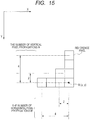
- Figs. 14 and 15 are diagrams for explaining a total number of pixels of the first and the second images.
- Fig. 15 is a diagram for explaining a pixel propagation direction and the number of pixel propagations.
- a total number of pixels in the horizontal direction of an image is defined as D
- a total number of pixels in the vertical direction of the image is defined as H. That is, the total number of pixels included in each of the first image R and the second image Ref is D ⁇ H.
- a direction from the target pixel R(x, y) to the reference pixel is the propagation direction.
- the number of propagations is 1, there is no propagation. That is, the coordinates of the target pixel are the same as the coordinates of the reference pixel.
- a horizontal pixel propagation direction is -X direction
- the number of horizontal pixel propagations M is 2 or 4.
- a vertical pixel propagation direction is -Y direction
- the number of vertical pixel propagations N is 2 or 4.
- a necessary register cost C1 is represented as follows.
- C 1 L * N ⁇ 1 * M + P
- P is a degree of parallelization of the pipelines.
- the degree of parallelization is the number of pipelines arranged in parallel.
- a capacity R2 of a register varies according to the number of amplifications, the degree of parallelization, the horizontal pixel propagation direction, and the vertical pixel propagation direction.
- a necessary register cost C2 is represented as follows.
- C 2 L * D * H
- an input pixel is one bit.
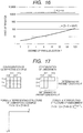
- the degree of parallelization P 128, the register cost of the image processing apparatus according to the embodiment can be about 1/100. Therefore, it is possible to prevent an increase of the capacity of the register. Thus, it is possible to efficiently perform image processing. In particular, it is possible to speed up the processing by increasing the number of parallelized pipelines (the degree of parallelization).
- the third intermediate data delayed by the delay elements 78a and 78b are supplied to the third operators 176a and 176b of the processing unit 170 over a pipeline.
- the third intermediate data A2 and A3 delayed by the delay elements 78a and 78b provided in the processing unit 70 of the first pipeline P1 are inputted into the third operators 176a and 176b of the processing unit 170 included in the second pipeline P2.
- the third operators 176a and 176b performs the third arithmetic operation based on the first intermediate data from the first operator 174 and the third intermediate data A2 and A3 from the delay elements 78a and 78b. By doing so, it is possible to use the third intermediate data A2 and A3 at an appropriate timing. Thereby it is possible to prevent the register cost from increasing.
- time axis adjustment of the third intermediate data is optimized by selection of the target pixel. By doing so, it is possible to refer to the third intermediate data A2 and A3 without increasing the amount of delay. Specifically, by appropriately setting positions of the target pixel of the first pipeline P1 and the target pixel of the second pipeline P2, it is possible to use the third intermediate data in the first pipeline P1 for an arithmetic operation in the second pipeline P2.
- a direction from the target pixel of the processing unit 170 of the second pipeline P2 to the target pixel of the processing unit 70 of the first pipeline P1 is opposite to the propagation direction.
- the target pixel of the processing unit 170 is shifted from the target pixel of the processing unit 70 in the +X direction.
- the propagation direction from the target pixel to the reference pixel is the -X direction.
- Fig. 17 is a diagram showing a configuration of a line memory of a comparative example and a configuration of the line memory in the image processing apparatus according to the embodiment.
- the configuration of the line memory in an image processing apparatus of the comparative example is shown in left side of Fig. 17
- the configuration of the line memory of the image processing apparatus according to the embodiment is shown in right side of Fig. 17 .
- image data of an original image is stored for each line, so that the capacity of each line is the same.
- the capacities of Y+0, Y+1, and Y+2 are the same.
- the reading position when the pipelines are parallelized moves according to N and M, so that an unnecessary portion is generated in a range in which the reading position moves. The unnecessary portion is not secured as a memory from the beginning.
- the line memory of the comparative example has a rectangular memory structure of X*Y.
- the reference pixels can be changed in a staircase pattern, so that the line memory is not required to have a rectangular shape.
- the line memory 81 does not have a portion corresponding to the pixels that can be reduced.
- the line memory 81 includes a plurality of lines whose capacities are different from each other. Portions that can be reduced depend on parameters of N, M, and P. It is possible to reduce the capacity of the line memory by the parameters determined by N, M, and P.
- a specific capacity of the line memory is represented by the formula shown in Fig. 17 .
- the delay adjustment control circuit 83 may fix the amount of delay of the delay elements 78 and 178.
- the amount of delay can be constant. Therefore, the delay elements 78 and 178 whose amount of delay is fixed may be provided without providing the delay adjustment control circuit 83.
- the number of pipelines to be parallelized may be three or more. Thereby, even when the processing is sped up, it is possible to suppress increase of the register capacity. Therefore, it is possible to more smoothly process complicated contents.
- the delay adjustment control circuit 83 may adjust the amount of delay.
- a configuration of a processing unit of an image processing apparatus according to the second embodiment will be described with reference to Fig. 18 . While a total number of propagations is three in the first embodiment, a total number of propagations in the second embodiment is four. Therefore, third operators 76a to 76c are provided in the processing unit 70 and third operators 176a to 176c are provided in the processing unit 170.
- Third intermediate data A4 of the third operator 76c is inputted into the third operator 176c through a delay element 78c.
- the amount of delay of the delay element 78c is greater than that of the delay elements 78a and 78b.
- the amount of delay of the delay element 78b is greater than that of the delay element 78a.
- Fig. 19 shows a processing flow of the configuration shown in Fig. 18 .
- the third intermediate data A4 of the processing unit 70a is inputted into the processing unit 170e through a delay of three unit processing periods. Then the processing unit 170e performs the third arithmetic operation by using the third intermediate data A2 to A4 inputted from the processing units 70a to 70c. Even in such a configuration, it is possible to obtain the same effect as that of the first embodiment.
- the amounts of delay of the third intermediate data A2 to A4 are different from each other by one unit processing period. In other words, the third intermediate data A2 to A4 from the three processing units 70a to 70c are inputted into one processing unit 170e through different amounts of delay.
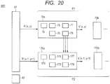
- Fig. 20 shows a configuration of an image processing apparatus according to another embodiment.
- the image processing apparatus 800 includes a line memory 81 that stores pixel data included in a first image and a second image, a plurality of pipelines P1 and P2 which are arranged in parallel and which have multi-stage processing units 70a, 70b, 170a, and 170b, each of which performs pipeline processing on the pixel data, and a line memory control circuit 82 that controls data reading from the line memory 81 to the processing units 70a, 70b, 170a, and 170b.
- the processing unit 70a includes a first operator 74 that performs a first arithmetic operation based on target pixel data corresponding to a target pixel of the first image and peripheral pixel data corresponding to peripheral pixels of a target pixel in the second image, a second operator 75 which performs a second arithmetic operation based on first intermediate data based on an arithmetic operation result of the first operator 74 and which calculates second intermediate data according to the first intermediate data of when the peripheral pixels are sequentially changed, a third operator 76 which performs a third arithmetic operation based on first intermediate data and which calculates third intermediate data according to the first intermediate data of when the peripheral pixels are sequentially changed, a register 77 that holds the second intermediate data of when the peripheral pixels are sequentially changed, and a delay element 78 that delays an arithmetic operation result of the third operator.
- An image processing method includes a step of developing pixel data included in a first image and a second image on a line memory, and a step of performing pipeline processing on the pixel data developed on the line memory by using multi-stage processing units of a plurality of pipelines arranged in parallel.
- the step of performing pipeline processing includes steps (a) to (f) described below.
- the image processing in the front monitoring system of a vehicle is described as an example.
- the image processing apparatus and the image processing method according to the embodiments can be applied to other than the front monitoring system.
- the image processing apparatus and the image processing method according to the embodiments can be applied to image recognition that accurately performs recognition of an object.
Landscapes
- Engineering & Computer Science (AREA)
- Physics & Mathematics (AREA)
- Theoretical Computer Science (AREA)
- General Physics & Mathematics (AREA)
- Multimedia (AREA)
- Signal Processing (AREA)
- Software Systems (AREA)
- General Engineering & Computer Science (AREA)
- Computer Vision & Pattern Recognition (AREA)
- Remote Sensing (AREA)
- Automation & Control Theory (AREA)
- Radar, Positioning & Navigation (AREA)
- Aviation & Aerospace Engineering (AREA)
- Electromagnetism (AREA)
- Mechanical Engineering (AREA)
- Human Computer Interaction (AREA)
- Image Processing (AREA)
- Traffic Control Systems (AREA)
Abstract
Description
- The disclosure of Japanese Patent Application No.
2016-061868 filed on March 25, 2016 - The present invention relates to an image processing apparatus, an image processing method, and a vehicle control apparatus.
- Demands for high-speed operations of data processing apparatuses which perform image processing and audio processing have increased year by year. In particular, for an image processing apparatus and an image recognition apparatus that are applied for vehicles, not only high speed processing but also a technique to accurately detect and recognize an object is required.
- This trend increases more and more following enlargement of image data due to development of multimedia and enrichment of contents in recent years.
- In particular, a huge amount of image data and a huge number of processing times are required to calculate motion information and distance information from high density pixel information in a front monitoring system. Therefore, it is anticipated that high performance will be further required hereafter.
- To meet the requirement, Japanese Unexamined Patent Application Publication No.
2003-296096 2003-296096 - Japanese Unexamined Patent Application Publication No.
2002-182905 2002-182905 - To control complicated contents in recent years, a complex control is required in which an arithmetic unit performs an arithmetic operation by using an arithmetic operation result of another arithmetic unit. Each arithmetic unit may refer to a processing result of an arithmetic unit arranged prior to a pre-stage arithmetic unit. In this case, in a pipeline configuration disclosed in Japanese Unexamined Patent Application Publication No.
2003-296096 - Further, when a method described in Japanese Unexamined Patent Application Publication No.
2002-182905 - In processing such as stereo processing and optical flow processing, there is a comparison image that is compared with a target image. In the stereo processing, different cameras handle an image of the same time. In the optical flow processing, the same camera handles images of different times. A case is considered in which an arithmetic operation is performed by using pixel data of the two images. The pipeline processing is configured by a plurality of stages. There are many arithmetic operations in which amplification and selection are repeated in each stage.
- The amplification is an arithmetic operation to calculate many selection candidates. The selection is an arithmetic operation to select optimal data from among a plurality of selection candidates. Therefore, in processing such as the stereo processing and the optical flow processing, a huge number of selection candidates that are intermediately generated or a huge amount of data for generating the selection candidates is generated. Therefore, when employing a method of performing optimization calculation of a function result applied to the stereo processing and the optical flow processing on a one-dimensional path, a problem occurs in which the number of registers that hold intermediately-generated data increases.
- Other objects and novel features will become apparent from the description of the present specification and the accompanying drawings.
- According to an embodiment, an image processing apparatus includes a plurality of pipelines arranged in parallel. Each of the pipelines has multi-stage processing units. Each of the processing units includes a first operator that performs a first arithmetic operation based on target pixel data corresponding to a target pixel of a first image and peripheral pixel data corresponding to peripheral pixels of the target pixel in a second image, a second operator which performs a second arithmetic operation based on first intermediate data based on an arithmetic operation result of the first operator and which calculates second intermediate data according to the first intermediate data of when the peripheral pixels are sequentially changed, a third operator which performs a third arithmetic operation based on first intermediate data and which calculates third intermediate data according to the first intermediate data of when the peripheral pixels are sequentially changed, a register that holds the second intermediate data of when the peripheral pixels are sequentially changed, and a delay element that delays the third intermediate data from the third operator.
- According to the embodiment, it is possible to efficiently perform image processing.
-
-
Fig. 1 is a block diagram showing a configuration of a vehicle on which an image processing apparatus is mounted. -
Fig. 2 is a control block diagram showing a circuit configuration of the image processing apparatus. -
Fig. 3 is a flowchart showing an image processing method. -
Fig. 4 is a processing flow showing image processing steps of the image processing method when using a general hardware configuration. -
Fig. 5 is a diagram for explaining pixels of a first and a second images in the image processing inFig. 4 . -
Fig. 6 is a diagram for explaining the image processing inFig. 4 . -
Fig. 7 is a diagram showing an execution flow in the processing shown inFig. 6 . -
Fig. 8 is a diagram for explaining a configuration in which pipeline processing inFig. 6 is parallelized. -
Fig. 9 is a diagram showing an execution flow in the processing shown inFig. 8 . -
Fig. 10 is a diagram for explaining a target pixel and peripheral pixels in an embodiment. -
Fig. 11 is a conceptual diagram for explaining processing in the image processing apparatus according to the embodiment. -
Fig. 12 is a diagram showing a configuration of a main part of the image processing apparatus. -
Fig. 13 is a diagram showing an execution flow in the processing shown inFig. 12 . -
Fig. 14 is a diagram showing pixels included in an image. -
Fig. 15 is a diagram for explaining a pixel propagation direction of and the number of pixel propagations. -
Fig. 16 is a graph showing a relationship between a degree of parallelization and a cost of register. -
Fig. 17 is a diagram showing a configuration of a line memory. -
Fig. 18 is a diagram schematically showing a configuration of a processing unit of an image processing apparatus according to a second embodiment. -
Fig. 19 is a diagram showing an execution flow in the processing shown inFig. 18 . -
Fig. 20 is a block diagram showing a configuration of an image processing apparatus according to another embodiment. - For clarity of explanation, the following description and drawings are appropriately omitted and simplified. The components shown in the drawings as functional blocks that perform various processing can be formed by a CPU, a memory, and other circuits as hardware and are realized by a program and the like loaded in a memory as software. Therefore, it should be understood by those skilled in the art that the functional blocks can be realized in various forms by only hardware, only software, or a combination of these, and the functional blocks are not limited to any one of hardware, software, and a combination of these. In the drawings, the same components are denoted by the same reference symbols and redundant description is omitted as appropriate.
- The program described above can be stored in various types of non-transitory computer readable media and supplied to a computer. The non-transitory computer readable media include various types of tangible storage media. Examples of the non-transitory computer readable media include a magnetic recording medium (for example, flexible disk, magnetic tape, and hard disk drive), a magneto-optical recording medium (for example, magneto-optical disk), a CD-ROM (Read Only Memory), a CD-R, a CD-R/W, and a semiconductor memory (for example, mask ROM, PROM (Programmable ROM), EPROM (Erasable PROM), flash ROM, and RAM (Random Access Memory)). The program may be supplied to a computer by various types of transitory computer readable media. Examples of the transitory computer readable media include an electrical signal, an optical signal, and an electromagnetic wave. The transitory computer readable media can supply the program to a computer through a wired communication path such as an electrical wire and an optical fiber or a wireless communication path.
- An image processing apparatus according to the embodiment is an image processing apparatus that performs pipeline processing on two images in parallel. That is, the image processing apparatus includes a plurality of pipelines arranged in parallel. Each pipeline includes multi-stage processing units. Data calculated by the processing unit is outputted to a post-stage processing unit. Thereby, the pipeline processing can be performed.
- For example, the two images are a stereo image captured at the same time by a stereo camera having two cameras in a left-right direction or two images captured at different timings by one camera. It is possible to obtain distance information and motion information of a pattern by performing pattern matching in the stereo processing and the optical flow processing. As the pattern matching, it is possible to use semi-global matching described in "Accurate and Efficient Stereo Processing by Semi-Global Matching and Mutual Information", Internet search: http://www.robotic.dlr.de/fileadmin/robotic/hirschmu/cvpr05hh.pdf.
- In the embodiment, an example will be described in which image processing is performed on a stereo image captured by a stereo camera mounted on a vehicle. Further, the image processing apparatus is used for a front monitoring system of a vehicle. It is possible to perform automatic control of a vehicle based on an image processing result of the image processing apparatus.
- First, a configuration of a vehicle on which an image processing apparatus is mounted will be described.
Fig. 1 is a diagram showing a control configuration of avehicle 1. Thevehicle 1 has acamera 2, a camera ECU (Electronic Control Unit) 3, anEUC 4, abrake ECU 5, anaccelerator ECU 6, and asteering ECU 7. Thevehicle 1 includes not only a normal passenger car, but also a bus, a truck, and the like. - The
camera 2, thecamera ECU 3, theEUC 4, thebrake ECU 5, theaccelerator ECU 6, and thesteering ECU 7 are mounted on thevehicle 1. Further, thevehicle 1 is provided with an engine, a brake, a steering, wheels, and the like. Control units such as thecamera ECU 3, theEUC 4, thebrake ECU 5, theaccelerator ECU 6, and thesteering ECU 7 are realized by hardware such as a microcomputer and software such as a program loaded into a memory. - The
camera 2 is a stereo camera having two cameras installed in left and right positions of thevehicle 1. Thecamera 2 captures an image in front of thevehicle 1. A stereo image captured by two cameras of thecamera 2 is outputted to thecamera ECU 3. Thecamera ECU 3 has an image processing apparatus and performs image processing on the stereo image. Then, thecamera ECU 3 outputs an image processing result to theECU 4. For example, thecamera ECU 3 calculates a distance from thevehicle 1 to an obstacle based on the image processing result. - The
ECU 4 has a control unit that controls thevehicle 1 based on the image processing result. For example, theECU 4 outputs a control signal to control thebrake ECU 5, theaccelerator ECU 6, and thesteering ECU 7. Thebrake ECU 5 controls a brake of thevehicle 1 according to the control signal. Theaccelerator ECU 6 controls an accelerator of thevehicle 1. Thesteering ECU 7 controls a steering of thevehicle 1. TheECU 4 outputs the control signal according to the image processing result, so that it is possible to automatically control thevehicle 1 by means of a system instead of a human being. - Next, the
camera ECU 3, which is the image processing apparatus according to the embodiment, will be described with reference toFig. 2. Fig. 2 is a control block diagram showing a circuit configuration of thecamera ECU 3. Thecamera ECU 3 has at least one CPU (Central Processing Unit) 22, alocal memory 23, anexternal memory interface 24, aninternal bus 25, at least one DSP (Digital Signal Processor) 26, aspecial hardware 27, aninterface 28, acamera interface 29, and acamera interface 30. - The camera interfaces 29 30 are interfaces for inputting an image from the
camera 2. For example, an image captured by a left camera of thecamera 2 is inputted into thecamera ECU 3 through thecamera interface 29. An image captured by a right camera of thecamera 2 is inputted into thecamera ECU 3 through thecamera interface 30. Here, the image captured by the left camera of thecamera 2 is defined as a first image and the image captured by the right camera of thecamera 2 is defined as a second image. The number of pixels in the first image is the same as that in the second image. - The
internal bus 25 has a bus line that couples theCPUs 22, thelocal memory 23, theexternal memory interface 24, theDSPs 26, thespecial hardware 27, thecamera interface 29, and thecamera interface 30 together. Theinterface 28 is an interface for inputting/outputting data from/to theECU 4. Theexternal memory interface 24 is an interface for inputting/outputting data from/to an external memory not shown in the drawings. - The
local memory 23 stores pixel data included in the first image and the second image. TheCPUs 22 integrally control each of thelocal memory 23, theexternal memory interface 24, theinternal bus 25, theDSPs 26, thespecial hardware 27, theinterface 28, thecamera interface 29, and thecamera interface 30. - The
CPUs 22, theDSPs 26, and thespecial hardware 27 are hardware for implementing the image processing method according to the embodiment. That is, the image processing is performed in theCPUs 22, theDSPs 26, and thespecial hardware 27. TheDSPs 26 and thespecial hardware 27 include a line memory which is an internal memory. - Next, an image processing method in the
camera ECU 3 will be described with reference toFig. 3. Fig. 3 is a flowchart showing the image processing method in thecamera ECU 3. - First, the
camera ECU 3 takes in a camera image (first image and second image) captured by thecamera 2 through the camera interfaces 29 and 30 (S31) . Then, thecamera ECU 3 develops the camera image in an external memory through the external memory interface 24 (S32). - Next, the
camera ECU 3 develops pixel data developed in the external memory in the local memory 23 (S33). - The
camera ECU 3 performs image processing based on the pixel data stored in the local memory 23 (S34). Specifically, the image processing is performed when theCPUs 22, theDSPs 26, and the special hardware perform arithmetic operation processing on the pixel data. - The
camera ECU 3 outputs an image processing result to theECU 4 and the like (S35). For example, thecamera ECU 3 generates an output image based on the first and the second images captured by thecamera 2 in step S34. The output image is formed from image data whose number of pixels is the same as that of the first and the second images. Then, thecamera ECU 3 outputs the output image to theECU 4 as an image processing result. The number of pixels may be thinned or cut as needed. - The
ECU 4 may control thebrake ECU 5, theaccelerator ECU 6, and thesteering ECU 7 based on the image processing result. Thereby, the brake, the accelerator, and the steering are controlled. Therefore, it is possible to automatically control thevehicle 1. For example, a distance to an obstacle is obtained by the image processing apparatus. When it is determined that there is an obstacle nearby, theaccelerator ECU 6 eases up on the accelerator and thebrake ECU 5 applies the brake, so that thevehicle 1 decelerates. Alternatively, thesteering ECU 7 controls the steering so as to avoid the obstacle. - Next, the image processing in step S34 will be described with reference to
Fig. 4. Fig. 4 shows a processing flow when the image processing in step S34 is performed by thegeneral DSP 26 and thespecial hardware 27. - The
camera ECU 3 develops the pixel data, which is developed in the local memory, in an internal memory (S41). The internal memory is the line memory built in theDSP 26 or thespecial hardware 27. The internal memory stores image data used in the image processing. Then, thecamera ECU 3 performs anarithmetic operation 1 on the pixel data stored in the line memory (S42) and internally holds an arithmetic operation result of thearithmetic operation 1 in a register (S43). - Next, the
camera ECU 3 performs anarithmetic operation 2 by using the arithmetic operation result of thearithmetic operation 1 which is held in the register (S44) and internally holds an arithmetic operation result of thearithmetic operation 2 in the register (S45). Thecamera ECU 3 performs anarithmetic operation 3 by using the arithmetic operation result of thearithmetic operation 2 which is held in the register (S46) and internally holds an arithmetic operation result of thearithmetic operation 3 in the register (S47). -
Fig. 4 shows a flow in which the arithmetic operation and the internal holding are repeated three times. However, the number of repetition times is not limited to three. Thearithmetic operations 1 to 3 are, for example, a multiply-accumulate (MAC) operation. - Here, the processing flow shown in
Fig. 4 will be described with reference toFigs. 5 and6 .Fig. 5 is a diagram for explaining pixels of the first image and the second image.Fig. 6 is a diagram for explaining thearithmetic operations 1 to 3. Specifically,Fig. 6 shows processing performed in one stage of a pipeline. - As shown in
Fig. 5 , images are shown as a first image R and a second image Ref. A horizontal direction (cross direction) of the first image R and the second image Ref is defined as an X direction, and a vertical direction (longitudinal direction) of these is defined as a Y direction. Here, the first image R and the second image Ref are two-dimensional images having a total number of pixels D in the X direction (D is an integer greater than or equal to 2) and a total number of pixels H in the Y direction (H is an integer greater than or equal to 2). - Pixel coordinates of the first image R and the second image Ref are represented as (x, y). For example, a pixel of the pixel coordinates (x, y) in the first image R are represented as R(x, y). Similarly, a pixel of the pixel coordinates (x+1, y) in the second image Ref are represented as Ref(x+1, y). Here, x and y are arbitrary positive integers. Pixel data of each pixel of the first image R and the second image Ref is stored in the internal memory as described above.
- Here, the pixel of the pixel coordinates (x, y) of the first image R is defined as a target pixel. Further, a pixel located around the pixel coordinates (x, y) is defined as a peripheral pixel. For example, the peripheral pixels are L pixels of Ref(x, y) to Ref(x+d, y). Here, d is an arbitrary integer. It is designed so that the peripheral pixels include the same pixel coordinates as those of the target pixel.
-
Fig. 6 shows aprocessing unit 250 that performs image processing on a target pixel of R(x, y). Specifically,Fig. 6 shows image processing for calculating output pixel data V(x, y) from pixel data of the target pixel R(x, y). In the description below, the pixel data of the target pixel is defined as target pixel data, and the pixel data of the peripheral pixels is defined as peripheral pixel data. - First, processing in the
processing unit 250 will be described. Afirst operator 251 performs an arithmetic operation by using the target pixel data and the peripheral pixel data. The target pixel data is pixel data corresponding to the target pixel R(x, y) of the first image R. The peripheral pixel data is pixel data of pixels located around the coordinates (x, y) of the second image Ref. Specifically, the peripheral pixel data is pixel data corresponding to peripheral pixels Ref(x, y) to Ref(x+d, y). The number of peripheral pixels is L, so that Lfirst operators 251 are provided. Here, L = d + 1 (L and d are arbitrary positive integers). Each of the Lfirst operators 251 performs arithmetic operation processing based on two pixel data. Thereby, L arithmetic operation results are obtained. The arithmetic operation performed by thefirst operator 251 corresponds to step S42 inFig. 4 . - Each of L registers 252 holds an arithmetic operation result. Here, the arithmetic operation results held by the L registers 252 are represented as a data array Sc(x, y). The data array Sc(x, y) is formed from the L arithmetic operation results. The L is defined as the number of amplifications in the
first operator 251. Specifically, the number of amplifications L is the number of data generated for one target pixel R(x, y) in thefirst operator 251. For example, 128, 256, and the like are used as the number of amplifications L. Data holding by theregister 252 corresponds to step S43 inFig. 4 . - Specifically, the data array Sc(x, y) is generated by sequentially changing the peripheral pixels with respect to one target pixel R(x, y). More specifically, pixel data of L peripheral pixels are sequentially inputted into the
first operator 251. Then, the data array Sc(x, y) is generated based on amplification data generated by thefirst operator 251. - Then, the data array Sc(x, y) is inputted into
second operators 253a to 253d. InFig. 6 , four second operators 253 are provided and the four second operators 253 are identified as thesecond operators 253a to 253d, respectively. Further, data arrays S(x-1, y), S(x-1, y-1), S(x-2, y-1), and S(x+1, y-1) are inputted into thesecond operators 253a to 253d, respectively, from a line memory or another stage of pipeline processing. - The
second operators 253a to 253d perform a second arithmetic operation on the two inputted data arrays. Specifically, thesecond operators 253a to 253d update the data arrays S(x-1, y), S(x-1, y-1), S(x-2, y-1), and S(x+1, y-1) by using the data array Sc(x, y). The arithmetic operations performed by thesecond operators 253a to 253d correspond to step S44 inFig. 4 . - For example, the data array Sc(x, y) and the data array S(x-1, y) are inputted into the
second operator 253a. Then, thesecond operator 253a updates the data array S(x-1, y) by using the data array Sc(x, y). Similarly, thesecond operators 253b to 253d update S(x-1, y-1), S(x-2, y-1), and S(x+1, y-1) by using the data array Sc(x, y). The data arrays S(x-1, y), S(x-1, y-1), S(x-2, y-1), and S(x+1, y-1), which are generated by thesecond operators 253a to 253d, are defined as propagation data. - The propagation data is calculated by using amplification data calculated from two pixels. Specifically, the
second operators 253a to 253d perform an arithmetic operation by using amplification data for a target pixel and a reference pixel. For example, the coordinates of the target pixel of thesecond operator 253a is (x, y) and the coordinates of the reference pixel is (x-1, y). Similarly, the coordinates of the target pixel of thesecond operator 253b is (x, y) and the coordinates of the reference pixel is (x-1, y-1). - As described above, one amplification data is formed by L data arrays. Specifically, the
second operators 253a to 253d calculate the propagation data by using the amplification data for the target pixel and the amplification data for the reference pixel which is propagated from the target pixel in the X direction or the Y direction. - The data arrays S(x-1, y), S(x-1, y-1), S(x-2, y-1), and S(x+1, y-1), which are updated by the
second operators 253a to 253d, are held byregisters 255a to 255d, respectively. Data holding by theregisters 255a to 255d corresponds to step S45 inFig. 4 . Then, theregisters 255a to 255d output the data arrays S(x-1, y), S(x-1, y-1), S(x-2, y-1), and S(x+1, y-1) to athird operator 256. - The
third operator 256 performs a third arithmetic operation on the data arrays S(x-1, y), S(x-1, y-1), S(x-2, y-1), and S(x+1, y-1). By doing so, thethird operator 256 calculates a data array Ss(x, y). The arithmetic operation performed by thethird operator 256 corresponds to step S46 inFig. 4 . The data array Ss(x, y) generated by thethird operator 256 is defined as selection candidate data. - The selection candidate data is calculated by using the propagation data calculated from a plurality of pixels. In
Fig. 6 , the selection candidate data of the target pixel R(x, y) is calculated by using the propagation data calculated from four pixels. - The
third operator 256 outputs the data array Ss(x, y) to aregister 257. Theregister 257 holds the data array Ss(x, y). The holding of the selection candidate data by theregister 257 corresponds to step S47. - Then, the
register 257 sequentially outputs the data array Ss(x, y) to theselector 258. Theselector 258 selects optimal pixel data from the data array Ss(x, y) and outputs the pixel data as output pixel data Vx(x, y). Then, the output pixel data Vx(x, y) is developed in thelocal memory 23.
Here, the data capacities of the data arrays S(x-1, y), S(x-1, y-1), S(x-2, y-1), and S(x+1, y-1), which are the propagation data, tend to be large. For example, the capacity of the propagation data is represented as L*D*H. -
Fig. 7 shows an execution flow in the processing shown inFig. 6 . InFig. 7 , RD represents reading of pixel data from a line memory, EX represents an arithmetic operation performed by an operator, and ST represents writing to a register. EX is performed twice each time. However, EX may be performed once or three times or more. - One row in the horizontal direction corresponds to processing in each stage of a pipeline. For example, in the first stage of the pipeline, the reading RD, the arithmetic operation EX, the arithmetic operation EX, and the writing ST are performed by using R(x+4, y) as the target pixel, and in the second stage of the pipeline, the reading RD, the arithmetic operation EX, the arithmetic operation EX, and the writing ST are performed by using R(x+3, y) as the target pixel. That is to say, an execution timing of the arithmetic operation EX is shifted once for each stage.
- After the pipeline processing of one row along the X direction is completed, the pipeline processing is shifted by one pixel in the Y direction and the pipeline processing of the next row is performed. In
Fig. 7 , after the pipeline processing of one row where the Y coordinate is y is completed, the pipeline processing of one row where the Y coordinate is y+1 is performed. - Next, an example in which the processing shown in
Fig. 6 is processed by two pipelines arranged in parallel will be described with reference toFig. 8 . InFig. 8 , aprocessing unit 250 of a first pipeline and aprocessing unit 350 of a second pipeline perform processing in parallel. - The
processing unit 250 and theprocessing unit 350 have the same configuration. Afirst operator 251, aregister 252, a second operator 253, a register 255, athird operator 256, aregister 257, and aselector 258 of theprocessing unit 250 respectively correspond to afirst operator 351, aregister 352, a second operator 353, a register 355, athird operator 356, aregister 357, and aselector 358 of theprocessing unit 350. The processing of theprocessing unit 250 and theprocessing unit 350 is the same as the processing inFig. 6 , so that the description thereof is omitted. - The
processing unit 250 of the first pipeline defines R(x, y) as the target pixel and theprocessing unit 350 of the second pipeline defines R(x, y+1) as the target pixel. In other words, theprocessing unit 250 of the first pipeline and theprocessing unit 350 of the second pipeline define pixels one pixel shifted from each other in the Y direction as the target pixels. Therefore, the peripheral pixels are also one pixel shifted from each other in the Y direction. -
Fig. 9 is shows an execution flow in the processing shown inFig. 8 . InFig. 9 , RD represents reading of pixel data from a line memory, EX represents an arithmetic operation performed by an operator, and ST represents writing to a register. EX is performed twice each time. However, EX may be performed once or three times or more. - In
Fig. 8 , two pipelines perform pipeline processing in parallel. Specifically, theprocessing unit 250 of the first pipeline and theprocessing unit 350 of the second pipeline perform processing at the same time. - For example, when the
processing unit 250 of the first pipeline performs processing by defining R(x, y) as the target pixel, theprocessing unit 350 of the second pipeline performs processing by defining R(x, y+1) as the target pixel. In other words, inFig. 8 , the target pixels are shifted from each other by one pixel. Therefore, as shown inFig. 9 , the processing where R(x, y) is defined as the target pixel and the processing where R(x, y+1) is defined as the target pixel are performed at the same time. That is to say, a timing (RD) when theprocessing unit 250 of the first pipeline reads pixel data of the target pixel R(x, y) and a timing (RD) when theprocessing unit 350 of the second pipeline reads pixel data of the target pixel R(x, y+1) are the same. - Therefore, it is difficult for the parallel pipeline configuration shown in
Fig. 8 to use an arithmetic operation result of the other pipeline. In other words, it is difficult to use propagation data obtained by theprocessing unit 250 of the first pipeline for the processing of theprocessing unit 350 of the second pipeline. Specifically, the propagation data in the processing where the target pixel is R(x, y) in theprocessing unit 250 of the first pipeline cannot be used for the processing where the target pixel is the target pixel R(x, y+1) in theprocessing unit 350 of the second pipeline. - Therefore, the embodiment uses an image processing apparatus and an image processing method described below. A configuration of a processing unit of the image processing apparatus according to the embodiment will be described with reference to
Figs. 10 and11 .Fig. 10 is a diagram for explaining a target pixel and peripheral pixels of two processing units of pipelines arranged in parallel.Fig. 11 is a diagram showing an outline of aprocessing unit 50 of a first pipeline and aprocessing unit 150 of a second pipeline. - As described above, the first pipeline and the second pipeline perform pipeline processing in parallel. For example, the first pipeline and the second pipeline perform the pipeline processing by using pixels, which are one pixel shifted from each other in the Y direction, as target pixels. The first pipeline has multi-stage processing units to perform the pipeline processing. Similarly, the second pipeline has multi-stage processing units to perform the pipeline processing. The processing unit included in the first pipeline uses a pixel, whose Y coordinate is y, as the target pixel. The processing unit included in the second pipeline uses a pixel, whose Y coordinate is y+1, as the target pixel.
-
Fig. 11 shows a one-stage processing unit 50 in the first pipeline and a one-stage processing unit 150 in the second pipeline. As shown inFigs. 10 and11 , the target pixel of theprocessing unit 50 is R(x, y) and the target pixel of theprocessing unit 150 is R(x-1, y+1). - The
processing unit 50 includes afirst operator 51, aregister 52, asecond operator 53a,third operators 54b to 54d, afourth operator 56, aselector 58. Theprocessing unit 150 includes afirst operator 151, aregister 152, asecond operator 153a,third operators 154b to 154d, afourth operator 156, aregister 157, and aselector 158, and delayelements 59b to 59d. - First, processing in the
processing unit 50 will be described. Thefirst operator 51 performs a first arithmetic operation by using target pixel data and peripheral pixel data. The target pixel data is pixel data corresponding to the target pixel R(x, y) of the first image R. The peripheral pixel data is pixel data of pixels located around the coordinates (x, y) of the second image Ref. Specifically, the peripheral pixel data is pixel data corresponding to peripheral pixels Ref(x, y) to Ref(x+d, y). The number of peripheral pixels is L, so that Lfirst operators 51 are provided. Each of the Lfirst operators 51 performs arithmetic operation processing based on two pixel data. Thereby, L arithmetic operation results are obtained. - Each of L registers 52 holds an arithmetic operation result. Here, the arithmetic operation results held by the L registers 52 are represented as a data array Sc(x, y). The data array Sc(x, y) is formed from the L arithmetic operation results. The L is defined as the number of amplifications in the
first operator 51. Specifically, the number of amplifications L is the number of data generated for one target pixel R(x, y) in thefirst operator 51. For example, 128, 256, and the like are used as the number of amplifications L. - Specifically, the data array Sc(x, y) is generated by sequentially changing the peripheral pixels with respect to one target pixel R(x, y). More specifically, pixel data of L peripheral pixels are sequentially inputted into the
operator 51. Then, the data array Sc(x, y) is generated based on amplification data generated by thefirst operator 51. - Then, the data array Sc(x, y) is inputted into the
second operator 53a and thethird operators 54b to 54d. InFig. 11 , three third operators 54 are provided and they are identified as thethird operators 54b to 54d. Further, the data arrays S(x-1, y), S(x-1, y-1), S(x-2, y-1), and S(x+1, y-1) are respectively inputted into thesecond operator 53a and thethird operators 54b to 54d from a line memory or another stage of the pipeline processing. - The
second operator 53a and thethird operators 54b to 54d perform a second arithmetic operation or a third arithmetic operation on two inputted data arrays. Specifically, thesecond operator 53a and thethird operators 54b to 54d update the data arrays S(x-1, y), S(x-1, y-1), S(x-2, y-1), and S(x+1, y-1) by using the data array Sc(x, y). - For example, the data array Sc(x, y) and the data array S(x-1, y) are inputted into the
second operator 53a. Then, thesecond operator 53a updates the data array S(x-1, y) by using the data array Sc(x, y). This is a second arithmetic operation. - Similarly, the
third operators 54b to 54d update S(x-1, y-1), S(x-2, y-1), and S(x+1, y-1) by using the data array Sc(x, y). This is a third arithmetic operation. The data arrays S(x-1, y), S(x-1, y-1), S(x-2, y-1), and S(x+1, y-1), which are generated by thesecond operator 53a and thethird operators 54b to 54d, are defined as propagation data. The data arrays S(x-1, y), S(x-1, y-1), S(x-2, y-1), and S(x+1, y-1) are inputted into thefourth operator 56. - The
third operators 54b to 54d perform the third arithmetic operation by using amplification data of two pixels. Specifically, thethird operators 54b to 54d perform the third arithmetic operation by using amplification data of the target pixel and amplification data of the reference pixel. The target pixel of thethird operator 54b is R(x, y) and the reference pixel of thethird operator 54b is R(x-1, y-1). The target pixel of thethird operator 54c is R(x, y) and the reference pixel of thethird operator 54c is R(x-2, y-1). The target pixel of thethird operator 54d is R(x, y) and the reference pixel of thethird operator 54d is R(x+1, y-1). - The
fourth operator 56 performs a fourth arithmetic operation on the data arrays S(x-1, y), S(x-1, y-1), S(x-2, y-1), and S(x+1, y-1). By doing so, thefourth operator 56 calculates the data array Ss(x, y). The fourth arithmetic operation performed by thefourth operator 56 corresponds to step S46 inFig. 4 . The data array Ss(x, y) generated by thefourth operator 56 is defined as selection candidate data. - The selection candidate data is calculated by using propagation data calculated from a plurality of pixels. In
Fig. 6 , selection data of the target pixel R(x, y) is calculated by using propagation data calculated from four pixels. - The
fourth operator 56 outputs the data array Ss(x, y) to aregister 57. Theregister 57 holds the data array Ss(x, y). Then, theregister 57 sequentially outputs the data array Ss(x, y) to theselector 58. Theselector 58 selects optimal pixel data from the data array Ss(x, y) and outputs the pixel data as output pixel data Vx(x, y). Specifically, theselector 58 selects the lowest cost data from a plurality of data included in the data array Ss(x, y). - Next, processing in the
processing unit 150 will be described. Thefirst operator 151 performs a first arithmetic operation by using target pixel data and peripheral pixel data. The target pixel data is pixel data corresponding to the target pixel R(x+1, y+1) of the first image R. The peripheral pixel data is pixel data of pixels located around the coordinates (x+1, y+1) of the second image Ref. Specifically, the peripheral pixel data is pixel data corresponding to peripheral pixels Ref(x-1, y) to Ref(x-1+d, y). The number of peripheral pixels is L, so that Lfirst operators 51 are provided. Each of the Lfirst operators 51 performs arithmetic operation processing based on two pixel data. Thereby, L arithmetic operation results are obtained. - Each of L registers 152 holds an arithmetic operation result. Here, the arithmetic operation results held by the L registers 152 are represented as a data array Sc(x-1, y+1). The data array Sc(x-1, y+1) is formed from the L arithmetic operation results. The L is defined as the number of amplifications in the
first operator 151. Specifically, the number of amplifications L is the number of data generated for one target pixel R(x-1, y+1) in thefirst operator 151. For example, the number of amplifications L has a value of 128, 256, and the like. The number of amplifications of thefirst operator 51 and the number of amplifications of thefirst operator 151 are the same. - Specifically, the data array Sc(x-1, y+1) is generated by sequentially changing the peripheral pixels with respect to one target pixel R(x-1, y+1). More specifically, pixel data of L peripheral pixels are sequentially inputted into the
operator 151. Then, the data array Sc(x-1, y+1) is generated based on amplification data generated by thefirst operator 151. - Then, the data array Sc(x-1, y+1) is inputted into the
second operator 153a and thethird operators 154b to 154d. InFig. 11 , three third operators 154 are provided and they are identified as thethird operators 154b to 154d. Further, the data arrays S(x-2, y+1), S(x-2, y), S(x-3, y), and S(x, y) are respectively inputted into thesecond operator 153a and thethird operators 154b to 154d from a line memory or another stage of the pipeline processing. - The
second operator 153a and thethird operators 154b to 154d perform a second arithmetic operation or a third arithmetic operation on two inputted data arrays. Specifically, thesecond operator 153a and thethird operators 154b to 154d update the data arrays S(x-2, y+1), S(x-2, y), S(x-3, y), and S(x, y) by using the data array Sc(x-1, y+1). - For example, the data array Sc(x-1, y+1) and the data array S(x-2, y+1) are inputted into the
second operator 153a. Then, thesecond operator 153a updates the data array S(x-2, y+1) by using the data array Sc(x-1, y+1). This is a second arithmetic operation. - Similarly, the
third operators 154b to 154d update S(x-2, y), S(x-3, y), and S(x, y) by using the data array Sc(x-1, y+1). This is a third arithmetic operation. The data arrays S(x-2, y+1), S(x-2, y), S(x-3, y), and S(x, y), which are generated by thesecond operator 153a and thethird operators 154b to 154d, are defined as propagation data. The data arrays S(x-2, y), S(x-2, y), S(x-3, y), and S(x, y) are inputted into thefourth operator 156. - The
third operators 154b to 154d perform the third arithmetic operation by using amplification data of two pixels. Specifically, thethird operators 154b to 154d perform the third arithmetic operation by using amplification data of the target pixel and amplification data of the reference pixel. The target pixel of thethird operator 154b is R(x-1, y+1) and the reference pixel of thethird operator 154b is R(x-2, y). The target pixel of thethird operator 154c is R(x-1, y+1) and the reference pixel of thethird operator 154c is R (x-3, y). The target pixel of thethird operator 154d is R(x-1, y+1) and the reference pixel of thethird operator 154d is R (x, y). - Further, in the embodiment, the data arrays S(x-1, y-1), S(x-2, y-1), and S(x+1, y-1) generated by the
processing unit 50 are inputted into thethird operators 154b to 154d through thedelay elements 59b to 59d. Specifically, S(x-1, y-1) generated by thethird operator 54b is inputted into thethird operator 154b through thedelay element 59b. S(x-2, y-1) generated by thethird operator 54c is inputted into thethird operator 154c through thedelay element 59c. S (x+1, y-1) generated by thethird operator 54d is inputted into thethird operator 154d through thedelay element 59d. - The
fourth operator 156 performs a fourth arithmetic operation on S(x-2, y+1), S(x-2, y), S(x-3, y), and S(x, y). By doing so, thefourth operator 156 calculates the data array Ss(x-1, y+1). The data array Ss(x-1, y+1) generated by thefourth operator 156 is defined as selection candidate data. - The
fourth operator 156 outputs the calculated data array Ss(x-1, y+1) to theregister 157. Theregister 157 holds the data array Ss(x-1, y+1). Then, theregister 157 sequentially outputs the data array Ss to theselector 158. Theselector 158 selects optimal pixel data from the data array Ss(x-1, y+1) and outputs the pixel data as output pixel data Vx(x-1, y+1). For example, theselector 58 selects the lowest cost data from a plurality of data included in the data array Ss(x-1, y+1). - In this way, the propagation data generated by the
third operators 54b to 54d is inputted into thethird operators 154b to 154d through thedelay elements 59b to 59d. That is to say, thethird operators 154b to 154d perform the third arithmetic operation by using arithmetic operation results in theprocessing unit 50 of the first pipelines arranged in parallel. At this time, the timings when the propagation data is inputted into thethird operators 154b to 154d are adjusted by thedelay elements 59b to 59d. By doing so, it is possible to reduce the number of registers that hold the propagation data. - Next, a detailed configuration of the image processing apparatus according to the embodiment will be described with reference to
Fig. 12. Fig. 12 is a diagram showing a configuration of a main part of the image processing apparatus. - The
image processing apparatus 700 includes aline memory 81, a linememory control circuit 82, a delayadjustment control circuit 83, aprocessing unit 70, and aprocessing unit 170. Theprocessing unit 70 represents a one-stage processing unit included in a first pipeline. Theprocessing unit 170 represents a one-stage processing unit included in a second pipeline. The first pipeline and the second pipeline perform pipeline processing in parallel. - The
processing unit 70 has afirst operator 74, asecond operator 75,third operators register 77, and delayelements processing unit 170 has afirst operator 174, asecond operator 175,third operators register 177, and delayelements - The
line memory 81 stores pixel data of a first image and a second image. In theline memory 81, the pixel data included in the first image and the second image is developed. The linememory control circuit 82 controls theline memory 81. The linememory control circuit 82 controls data writing from thelocal memory 23 to theline memory 81. Further, the linememory control circuit 82 controls data reading from theline memory 81 to theprocessing units - Specifically, the line
memory control circuit 82 reads pixel data included in the first image and the second image, on which the pipeline processing is performed, from thelocal memory 23 and writes the pixel data into theline memory 81. The linememory control circuit 82 reads pixel data necessary for the processing of theprocessing unit 70 and theprocessing unit 170 from theline memory 81 at an appropriate timing. When the image processing apparatus performs semi-global matching, theline memory 81 stores pixel data of a part of the first and the second images. Then, the linememory control circuit 82 supplies the pixel data read from theline memory 81 to theprocessing units adjustment control circuit 83 controls the amount of delay of thedelay elements - The pixel data read from the
line memory 81 is inputted into thefirst operators first operators first operators first operators first operator 51 and thefirst operator 151 shown inFig. 11 . - The pixel data of a plurality of peripheral pixels is sequentially inputted into the
first operators first operators second operator 75 and thethird operators first operator 74 is first intermediate data. The first intermediate data corresponds to the amplification data described above. - The
first operators first operators first operators first operators first operators - The
second operators second operators registers second operators registers second operator 75 performs the second arithmetic operation by using the second intermediate data based on the first intermediate data that has already been generated and the first intermediate data that is newly generated. For example, the second arithmetic operation is a multiply-accumulate operation. - Then, the arithmetic operation results of the
second operators registers second operators second operators second operators Fig. 11 . - Similarly, the first intermediate data from the
first operator 74 are sequentially inputted into thethird operators third operators third operators third operators third operators line memory 81 may be inputted into thethird operators - Specifically, the
third operators third operators - The arithmetic operation results of the
third operators third operator 76a is referred to as A2 and the third intermediate data calculated by thethird operator 76b is referred to as A3. The third intermediate data A2 is inputted into the third operator 17 6a through the delay element 78a. he third intermediate data A3 is inputted into thethird operator 176b through thedelay element 78b. - The
third operators third operators 7 6a and 7 6b. Specifically, the first intermediate data from thefirst operator 174 and the third intermediate data A2 from thethird operator 76a are sequentially inputted into thethird operator 176a. Thethird operator 176a performs the third arithmetic operation based on the sequentially inputted two data. Similarly, the first intermediate data from thefirst operator 174 and the third intermediate data A3 from thethird operator 76b are sequentially inputted into thethird operator 176b. Thethird operator 176b performs the third arithmetic operation based on the sequentially inputted two data. - Data calculated by the
third operator 176a is defined as third intermediate data B2, and data calculated by thethird operator 176b is defined as third intermediate data B3. The third intermediate data B2 and B3 are outputted to a processing unit of another pipeline through thedelay elements - Although not shown in
Fig. 12 , theprocessing unit 70 generates output pixel data by using the second intermediate data calculated by thesecond operator 75 and the third intermediate data A2 and A3 calculated by thethird operators processing unit 170 generates output pixel data by using the second intermediate data calculated by thesecond operator 175 and the third intermediate data B2 and B3 calculated by thethird operators 176a and 17 6b. The processing of generating the output pixel data is the same as the processing performed by thefourth operators selectors Fig. 11 , so that the description thereof is omitted. -
Fig. 13 shows an execution flow in the processing shown inFig. 12 . InFig. 13 , RD represents reading of pixel data from a line memory, EX represents an arithmetic operation performed by an operator, and ST represents writing to a register. Further,Fig. 13 shows pipeline processing in a first pipeline P1 and pipeline processing in a second pipeline P2. Further,Fig. 13 shows five-stage processing units 70a to 70e included in the first pipeline P1 and five-stage processing units 170a to 170e included in the second pipeline P2. - Regarding the five-
stage processing units 70a to 70e, theprocessing unit 70a, theprocessing unit 70b, theprocessing unit 70c, theprocessing unit 70d, and theprocessing unit 70e are located in order from the most pre-stage side. Regarding the five-stage processing units 170a to 170e, theprocessing unit 170a, theprocessing unit 170b, theprocessing unit 170c, theprocessing unit 170d, and theprocessing unit 170e are located in order from the most pre-stage side. That is, the most pre-stage processing units in the pipelines P1 and P2 are theprocessing units - The Y coordinate of the target pixel in the first pipeline P1 is y, and the Y coordinate of the target pixel in the second pipeline P2 is y+1. In other words, the Y coordinate is different between pipelines in parallel. For example, in the
processing units 70a to 70e of the first pipeline P1, the Y coordinate of the target pixel is y, and in theprocessing units 170a to 170e of the second pipeline P2, the Y coordinate of the target pixel is y+1. In one pipeline, in the multi-stage processing units, the X coordinate of the target pixel varies by one from the X coordinate of the neighboring target pixel. For example, the X coordinates of theprocessing units - The timing of the processing on the target pixel (x+4, y) of the
processing unit 70a is the same as the timing of the processing on the target pixel (x+3, y+1) of theprocessing unit 170a. In the first pipe line P1, the processing timings of theprocessing units 70a to 70e are shifted from each other by one unit processing period. Here, the one unit processing period corresponds to a period of time in which one unit processing shown by one field inFig. 13 is performed. In other words, the one unit processing period corresponds to a period of time in which any one of the reading RD, the arithmetic operation EX, and the writing ST is performed. - Further, in each processing unit, the uppermost row corresponds to the second intermediate data and the second uppermost row corresponds to the third intermediate data calculated by the
third operator third operator 76b or 17 6b. Each processing unit is formed from four unit processing periods including (1) reading RD, (2) first arithmetic operation EX, (3) second arithmetic operation or third arithmetic operation EX, and (4) writing ST. - As shown in
Fig. 13 , in the oneprocessing unit 70, the timings of the arithmetic operation EX of thesecond operator 75 and thethird operators processing unit 170, the timings of the arithmetic operation EX of thesecond operator 175 and thethird operators - In the
processing unit 70b, processing for the target pixel R(x+3, y) is performed. The third intermediate data A3 generated by thethird operator 76b of theprocessing unit 70b is inputted into thethird operator 76b of theprocessing unit 170e through a delay of two unit processing periods. - In the
processing unit 70c, processing for the target pixel R(x+2, y) is performed. The third intermediate data A2 generated by thethird operator 76a of theprocessing unit 70c is inputted into thethird operator 76a of theprocessing unit 170e through a delay of one unit processing period. Theprocessing unit 170e performs processing for the target pixel R(x-1, y+1). The amount of delay by thedelay element 78b is greater than the amount of delay by thedelay element 78a. - In this way, different delays are given to the third intermediate data A2 and A3, so that it is possible to use the third intermediate data A2 and A3 in the third arithmetic operation in the
processing unit 170e. That is, thethird operators processing unit 170e included in the second pipeline P2 can use the third intermediate data A2 and A3 generated in the first pipeline P1. In other words, the third intermediate data A2 and A3 are inputted/outputted between the pipelines. By doing so, it is possible to reduce the capacity of a register for holding the third intermediate data. - Although
Fig. 13 shows only an example in which the third intermediate data A2 and A3 are inputted into theprocessing unit 170e, it is possible to input/output the third intermediate data A2 and A3 between a plurality ofprocessing units 70 and a plurality ofprocessing units 170 when the delayadjustment control circuit 83 sets an appropriate delay element. Thereby, it is possible to further reduce the capacity of the register. - For example, when each of the pipelines P1 and P2 has six stages or more of processing units, it is possible to supply the third intermediate data A2 and A3 generated by the
processing units processing unit 170. Further, when the number of parallel pipelines is increased, it is possible to increase the third intermediate data A2 and A3 that can be used by other pipelines. For example, inFig. 12 , when there is a third pipeline P3 in addition to the first pipeline P1 and the third pipeline P3, it is possible to input the third intermediate data B2 and B3 generated by thethird operator 176 into a processing unit of the third pipeline. - One or more of the
operators 74 to 76, theoperators 174 to 176, theoperators operators fourth operator 156 and thefourth operator 56 perform an arithmetic operation based on the formula (14). Further, thethird operator 176, thethird operator 76, the third operator 54, and the third operator 154 perform an arithmetic operation based on the formula (13). - In the embodiment, the
processing unit 70 of the first pipeline P1 defines a pixel located in a direction opposite to the propagation directions from the target pixel to the peripheral pixels as the target pixel. The reason of the above will be described with reference toFigs. 14 and15 .Fig. 14 is a diagram for explaining a total number of pixels of the first and the second images.Fig. 15 is a diagram for explaining a pixel propagation direction and the number of pixel propagations. - As shown in
Fig. 14 , a total number of pixels in the horizontal direction of an image is defined as D, and a total number of pixels in the vertical direction of the image is defined as H. That is, the total number of pixels included in each of the first image R and the second image Ref is D×H. - As shown in
Fig. 15 , in the third operator, a direction from the target pixel R(x, y) to the reference pixel is the propagation direction. When the number of propagations is 1, there is no propagation. That is, the coordinates of the target pixel are the same as the coordinates of the reference pixel. Specifically, a horizontal pixel propagation direction is -X direction, and the number of horizontal pixel propagations M is 2 or 4. A vertical pixel propagation direction is -Y direction, and the number of vertical pixel propagations N is 2 or 4. - In the image processing method according to the embodiment, a necessary register cost C1 is represented as follows.

- Here, P is a degree of parallelization of the pipelines. The degree of parallelization is the number of pipelines arranged in parallel. A capacity R2 of a register varies according to the number of amplifications, the degree of parallelization, the horizontal pixel propagation direction, and the vertical pixel propagation direction.
- On the other hand, when the image processing method according to the embodiment is not used, a necessary register cost C2 is represented as follows.

- As shown in
Fig. 14 , D is the total number of pixels in the horizontal direction of the image and H is the total number of pixels in the vertical direction of the image. Here,Fig. 16 shows a register cost in a case of N = 2, M = 4, D = 640, and H = 480. InFig. 16 , an input pixel is one bit. When the degree of parallelization P = 128, the register cost of the image processing apparatus according to the embodiment can be about 1/100. Therefore, it is possible to prevent an increase of the capacity of the register. Thus, it is possible to efficiently perform image processing. In particular, it is possible to speed up the processing by increasing the number of parallelized pipelines (the degree of parallelization). - Further, the third intermediate data delayed by the
delay elements third operators processing unit 170 over a pipeline. Specifically, the third intermediate data A2 and A3 delayed by thedelay elements processing unit 70 of the first pipeline P1 are inputted into thethird operators processing unit 170 included in the second pipeline P2. Then, thethird operators first operator 174 and the third intermediate data A2 and A3 from thedelay elements - Further, time axis adjustment of the third intermediate data is optimized by selection of the target pixel. By doing so, it is possible to refer to the third intermediate data A2 and A3 without increasing the amount of delay. Specifically, by appropriately setting positions of the target pixel of the first pipeline P1 and the target pixel of the second pipeline P2, it is possible to use the third intermediate data in the first pipeline P1 for an arithmetic operation in the second pipeline P2. When the
third operators processing unit 170 of the second pipeline P2 to the target pixel of theprocessing unit 70 of the first pipeline P1 is opposite to the propagation direction. For example, as shown inFig. 10 , the target pixel of theprocessing unit 170 is shifted from the target pixel of theprocessing unit 70 in the +X direction. In theprocessing unit 70, the propagation direction from the target pixel to the reference pixel is the -X direction. Thereby, it is possible to use the third intermediate data A2 and A3 with a small amount of delay. - Further, according to the image processing apparatus of the embodiment, it is possible to reduce the capacity of the line memory. A reduction of the line memory will be described with reference to
Fig. 17. Fig. 17 is a diagram showing a configuration of a line memory of a comparative example and a configuration of the line memory in the image processing apparatus according to the embodiment. The configuration of the line memory in an image processing apparatus of the comparative example is shown in left side ofFig. 17 , and the configuration of the line memory of the image processing apparatus according to the embodiment is shown in right side ofFig. 17 . - In the comparative example, image data of an original image is stored for each line, so that the capacity of each line is the same. For example, the capacities of Y+0, Y+1, and Y+2 are the same. On the other hand, in the configuration of the embodiment, the reading position when the pipelines are parallelized moves according to N and M, so that an unnecessary portion is generated in a range in which the reading position moves. The unnecessary portion is not secured as a memory from the beginning.
- As shown in
Fig. 17 , the line memory of the comparative example has a rectangular memory structure of X*Y. On the other hand, in the embodiment, the reference pixels can be changed in a staircase pattern, so that the line memory is not required to have a rectangular shape. For example, in the Y+0 line, it is required to hold pixels up to X+3. On the other hand, it is possible to reduce the number of pixels to be hold, up to X+2 in the Y+1 line and up to X+1 in the Y+2 line. Therefore, theline memory 81 does not have a portion corresponding to the pixels that can be reduced. - As described above, according to the embodiment, it is possible to reduce the capacity of the line memory by optimizing a memory structure for processing of the processing unit. Specifically, the
line memory 81 includes a plurality of lines whose capacities are different from each other. Portions that can be reduced depend on parameters of N, M, and P. It is possible to reduce the capacity of the line memory by the parameters determined by N, M, and P. A specific capacity of the line memory is represented by the formula shown inFig. 17 . - When the number of parallel pipelines, the number of stages in each pipeline, the number of pixels in an image, the number of amplifications, the number of propagations, and the like are determined, the delay
adjustment control circuit 83 may fix the amount of delay of thedelay elements delay elements adjustment control circuit 83. The number of pipelines to be parallelized may be three or more. Thereby, even when the processing is sped up, it is possible to suppress increase of the register capacity. Therefore, it is possible to more smoothly process complicated contents. When the degree of parallelization, the number of propagations, and the like vary, the delayadjustment control circuit 83 may adjust the amount of delay. - A configuration of a processing unit of an image processing apparatus according to the second embodiment will be described with reference to
Fig. 18 . While a total number of propagations is three in the first embodiment, a total number of propagations in the second embodiment is four. Therefore,third operators 76a to 76c are provided in theprocessing unit 70 andthird operators 176a to 176c are provided in theprocessing unit 170. - Third intermediate data A4 of the
third operator 76c is inputted into thethird operator 176c through adelay element 78c. Here, the amount of delay of thedelay element 78c is greater than that of thedelay elements delay element 78b is greater than that of thedelay element 78a. -
Fig. 19 shows a processing flow of the configuration shown inFig. 18 . The third intermediate data A4 of theprocessing unit 70a is inputted into theprocessing unit 170e through a delay of three unit processing periods. Then theprocessing unit 170e performs the third arithmetic operation by using the third intermediate data A2 to A4 inputted from theprocessing units 70a to 70c. Even in such a configuration, it is possible to obtain the same effect as that of the first embodiment. The amounts of delay of the third intermediate data A2 to A4 are different from each other by one unit processing period. In other words, the third intermediate data A2 to A4 from the threeprocessing units 70a to 70c are inputted into oneprocessing unit 170e through different amounts of delay. -
Fig. 20 shows a configuration of an image processing apparatus according to another embodiment. Theimage processing apparatus 800 includes aline memory 81 that stores pixel data included in a first image and a second image, a plurality of pipelines P1 and P2 which are arranged in parallel and which havemulti-stage processing units memory control circuit 82 that controls data reading from theline memory 81 to theprocessing units processing unit 70a includes afirst operator 74 that performs a first arithmetic operation based on target pixel data corresponding to a target pixel of the first image and peripheral pixel data corresponding to peripheral pixels of a target pixel in the second image, asecond operator 75 which performs a second arithmetic operation based on first intermediate data based on an arithmetic operation result of thefirst operator 74 and which calculates second intermediate data according to the first intermediate data of when the peripheral pixels are sequentially changed, athird operator 76 which performs a third arithmetic operation based on first intermediate data and which calculates third intermediate data according to the first intermediate data of when the peripheral pixels are sequentially changed, aregister 77 that holds the second intermediate data of when the peripheral pixels are sequentially changed, and adelay element 78 that delays an arithmetic operation result of the third operator. - An image processing method according to an embodiment includes a step of developing pixel data included in a first image and a second image on a line memory, and a step of performing pipeline processing on the pixel data developed on the line memory by using multi-stage processing units of a plurality of pipelines arranged in parallel.
- The step of performing pipeline processing includes steps (a) to (f) described below.
- (a) a first arithmetic operation step in which a first operator performs an arithmetic operation based on target pixel data corresponding to a target pixel of the first image and peripheral pixel data corresponding to peripheral pixels of the target pixel in the second image,
- (b) a second arithmetic operation step in which a second operator performs a second arithmetic operation based on first intermediate data based on an arithmetic operation result in the first arithmetic operation step,
- (c) a step in which a register holds second intermediate data according to an arithmetic operation result of the second operator,
- (d) a third arithmetic operation step in which a third operator performs a third arithmetic operation based on the first intermediate data,
- (e) a step in which a delay element delays third intermediate data according to an arithmetic operation result of the third operator, and
- (f) a step which repeatedly performs steps (a) to (e) by sequentially changing the peripheral pixels.
- In the above description, the image processing in the front monitoring system of a vehicle is described as an example. However, the image processing apparatus and the image processing method according to the embodiments can be applied to other than the front monitoring system. The image processing apparatus and the image processing method according to the embodiments can be applied to image recognition that accurately performs recognition of an object.
- While the invention made by the inventors has been specifically described based on the embodiments, it is needless to say that the present invention is not limited to the embodiments and may be variously modified without departing from the scope of the invention.
Claims (19)
- An image processing apparatus comprising:a line memory that stores pixel data included in a first image and a second image;a plurality of pipelines which are arranged in parallel and which have multi-stage processing units, each of which performs pipeline processing on the pixel data; anda line memory control circuit that controls data reading from the line memory to the processing units,wherein each of the processing units includesa first operator that performs a first arithmetic operation based on target pixel data corresponding to a target pixel of the first image and peripheral pixel data corresponding to peripheral pixels of the target pixel in the second image,a second operator which performs a second arithmetic operation based on first intermediate data based on an arithmetic operation result of the first operator and which calculates second intermediate data according to the first intermediate data of when the peripheral pixels are sequentially changed,a third operator which performs a third arithmetic operation based on first intermediate data and which calculates third intermediate data according to the first intermediate data of when the peripheral pixels are sequentially changed,a register that holds the second intermediate data of when the peripheral pixels are sequentially changed, anda delay element that delays the third intermediate data from the third operator.
- The image processing apparatus according to claim 1,wherein the plurality of pipelines include a first pipeline and a second pipeline,wherein the third intermediate data delayed by the delay element provided in the processing unit in the first pipeline is inputted into the third operator of the processing unit included in the second pipeline, andwherein the third operator performs the third arithmetic operation based on the first intermediate data from the first operator and the third intermediate data from the delay element.
- The image processing apparatus according to claim 2,wherein the third operator performs the third arithmetic operation on the target pixel and a reference pixel shifted from the target pixel in a propagation direction, andwherein a target pixel of a processing unit of the second pipeline is shifted from a target pixel of a processing unit of the first pipeline in a direction opposite to the propagation direction.
- The image processing apparatus according to claim 1,wherein the processing unit calculates a plurality of selection candidates by performing an arithmetic operation on the target pixel data and defines one selection candidate selected from the selection candidates as output pixel data.
- The image processing apparatus according to any of claims 1 to 4,wherein the line memory includes a plurality of lines whose capacities are different from each other.
- The image processing apparatus according to any of claims 1 to 5,wherein the register inputs the held second intermediate data into the second operator, andwherein the second operator performs the second arithmetic operation based on the first intermediate data and the second intermediate data.
- The image processing apparatus according to any of claims 1 to 6, further comprising:a delay adjustment control circuit that adjusts an amount of delay of the delay element.
- The image processing apparatus according to any of claims 1 to 7,wherein the first image and the second image are a stereo image captured by a stereo camera.
- The image processing apparatus according to any of claims 1 to 7,wherein two images captured by one camera at different timings are the first image and the second image.
- A vehicle control apparatus comprising:the image processing apparatus according to any of claims 1 to 9;at least one camera that captures the first image and the second image; anda control unit that controls a vehicle by using a processing result of the image processing apparatus.
- An image processing method comprising the steps of:developing pixel data included in a first image and a second image on a line memory; andperforming pipeline processing on the pixel data developed on the line memory by using multi-stage processing units of a plurality of pipelines arranged in parallel,wherein the step of performing pipeline processing includes(a) a first arithmetic operation step in which a first operator performs an arithmetic operation based on target pixel data corresponding to a target pixel of the first image and peripheral pixel data corresponding to peripheral pixels of the target pixel in the second image,(b) a second arithmetic operation step in which a second operator performs a second arithmetic operation based on first intermediate data based on an arithmetic operation result in the first arithmetic operation step,(c) a step in which a register holds second intermediate data based on an arithmetic operation result of the second operator,(d) a third arithmetic operation step in which a third operator performs a third arithmetic operation based on the first intermediate data,(e) a step in which a delay element delays third intermediate data according to an arithmetic operation result of the third operator, and(f) a step which repeatedly performs steps (a) to (e) by sequentially changing the peripheral pixels.
- The image processing method according to claim 11,wherein the plurality of pipelines include a first pipeline and a second pipeline,wherein the third intermediate data delayed by the delay element provided in the processing unit in the first pipeline is inputted into the third operator of the processing unit included in the second pipeline, andwherein the third operator performs the third arithmetic operation based on the first intermediate data from the first operator and the third intermediate data from the delay element.
- The image processing method according to claim 12,wherein the third operator performs the third arithmetic operation on the target pixel and a reference pixel shifted from the target pixel in a propagation direction, andwherein a target pixel of the processing unit of the second pipeline is shifted from a target pixel of a processing unit of the first pipeline in a direction opposite to the propagation direction.
- The image processing method according to claim 11,wherein the processing unit calculates a plurality of selection candidates by performing an arithmetic operation on the target pixel data and defines one selection candidate selected from the selection candidates as output pixel data.
- The image processing method according to any of claims 11 to 14,wherein the line memory includes a plurality of lines whose capacities are different from each other.
- The image processing method according to any of claims 11 to 15,wherein the register inputs the held second intermediate data into the second operator, andwherein the second operator performs the second arithmetic operation based on the first intermediate data and the second intermediate data in the step (b).
- The image processing method according to any of claims 11 to 16,wherein an amount of delay of the delay element is adjusted.
- The image processing method according to any of claims 11 to 17,wherein the first image and the second image are a stereo image captured by two cameras.
- The image processing method according to any of claims 11 to 17,wherein two images captured by one camera at different timings are the first image and the second image.
Applications Claiming Priority (1)
| Application Number | Priority Date | Filing Date | Title |
|---|---|---|---|
| JP2016061868A JP2017174291A (en) | 2016-03-25 | 2016-03-25 | Image processing apparatus, image processing method, and automobile control apparatus |
Publications (1)
| Publication Number | Publication Date |
|---|---|
| EP3223233A1 true EP3223233A1 (en) | 2017-09-27 |
Family
ID=58464183
Family Applications (1)
| Application Number | Title | Priority Date | Filing Date |
|---|---|---|---|
| EP17162563.5A Withdrawn EP3223233A1 (en) | 2016-03-25 | 2017-03-23 | Image processing apparatus; image processing method; and vehicle control apparatus |
Country Status (5)
| Country | Link |
|---|---|
| US (1) | US10229472B2 (en) |
| EP (1) | EP3223233A1 (en) |
| JP (1) | JP2017174291A (en) |
| KR (1) | KR20170113132A (en) |
| CN (1) | CN107229451A (en) |
Cited By (1)
| Publication number | Priority date | Publication date | Assignee | Title |
|---|---|---|---|---|
| CN111008696A (en) * | 2018-10-04 | 2020-04-14 | 富士通株式会社 | Optimization device and method for controlling the same |
Families Citing this family (3)
| Publication number | Priority date | Publication date | Assignee | Title |
|---|---|---|---|---|
| JP6976744B2 (en) * | 2017-06-29 | 2021-12-08 | キヤノン株式会社 | Imaging devices, imaging systems, and moving objects |
| JP7527755B2 (en) * | 2018-02-09 | 2024-08-05 | キヤノン株式会社 | Photoelectric conversion device and imaging system |
| CN119484723B (en) * | 2024-10-22 | 2025-11-07 | 珠海奔图电子有限公司 | Image pipeline execution method, device, chip, electronic equipment and storage medium |
Citations (3)
| Publication number | Priority date | Publication date | Assignee | Title |
|---|---|---|---|---|
| JP2002182905A (en) | 2000-12-18 | 2002-06-28 | Seiko Epson Corp | Digital signal processor |
| JP2003296096A (en) | 2002-04-01 | 2003-10-17 | Sony Computer Entertainment Inc | Serial arithmetic pipeline, arithmetic unit, arithmetic logic circuit, and arithmetic method by serial arithmetic pipeline |
| US20060090060A1 (en) * | 2002-02-18 | 2006-04-27 | Wolfram Drescher | Method and arrangement for bringing together data on parallel data paths |
Family Cites Families (3)
| Publication number | Priority date | Publication date | Assignee | Title |
|---|---|---|---|---|
| JP3729540B2 (en) * | 1995-09-08 | 2005-12-21 | 株式会社ルネサステクノロジ | Image processing device |
| JPH11308574A (en) * | 1998-04-22 | 1999-11-05 | Sony Corp | Scanning line number conversion apparatus and method |
| JP5523035B2 (en) * | 2009-09-18 | 2014-06-18 | パナソニック株式会社 | Image processing apparatus and image processing method |
-
2016
- 2016-03-25 JP JP2016061868A patent/JP2017174291A/en active Pending
-
2017
- 2017-02-02 US US15/422,700 patent/US10229472B2/en active Active
- 2017-03-16 KR KR1020170033321A patent/KR20170113132A/en not_active Withdrawn
- 2017-03-23 CN CN201710175991.0A patent/CN107229451A/en active Pending
- 2017-03-23 EP EP17162563.5A patent/EP3223233A1/en not_active Withdrawn
Patent Citations (3)
| Publication number | Priority date | Publication date | Assignee | Title |
|---|---|---|---|---|
| JP2002182905A (en) | 2000-12-18 | 2002-06-28 | Seiko Epson Corp | Digital signal processor |
| US20060090060A1 (en) * | 2002-02-18 | 2006-04-27 | Wolfram Drescher | Method and arrangement for bringing together data on parallel data paths |
| JP2003296096A (en) | 2002-04-01 | 2003-10-17 | Sony Computer Entertainment Inc | Serial arithmetic pipeline, arithmetic unit, arithmetic logic circuit, and arithmetic method by serial arithmetic pipeline |
Non-Patent Citations (8)
| Title |
|---|
| "MC14557B 1-to-64 Bit Variable Length Shift Register", 1 June 2011, ON SEMICONDUCTORS, Denver, Colorado, USA, article ANONYMOUS, pages: 1 - 8, XP055489142 * |
| "Texas Instruments Production Data Information", 1 March 1988, TEXAS INSTRUMENTS, Dallas, Texas 75265, US, ISSN: 0013-9165, article ANONYMOUS: "SN54LS31, SN74LS31 Delay Elemenst", pages: 1 - 6, XP055488217 * |
| A. KAYAALP ET AL: "Near Real-Time Stereo Range Detection Using a Pipeline Architecture", IEEE TRANSACTIONS ON SYSTEMS, MAN, AND CYBERNETICS, vol. 20, no. 6, 1 November 1990 (1990-11-01), pages 1461 - 1469, XP055380248, Retrieved from the Internet <URL:http://ieeexplore.ieee.org/document/61216/> * |
| BAKHTIAR AFFENDI ROSDI ET AL: "Replacement of Register with Delay Element for Reducing the Area of Pipelined Circuits", CIRCUITS AND SYSTEMS, 2006. APCCAS 2006. IEEE ASIA PACIFIC CONFERENCE ON, IEEE, PISCATAWAY, NJ, USA, 1 December 2006 (2006-12-01), pages 801 - 804, XP031070956 * |
| HARIYAMA M ET AL: "FPGA implementation of a stereo matching processor based on window-parallel-and-pixel-parallel architecture", CIRCUITS AND SYSTEMS, 2005. 48TH MIDWEST SYMPOSIUM ON CINICINNATI, OHIO AUGUST 7-10, 2005, US, 7 August 2005 (2005-08-07), pages 1219 - 1222, XP010895363 * |
| KAYAALP A E ET AL: "A PIPELINE ARCHITECTURE FOR NEAR REAL-TIME STEREO RANGE DETECTION", OPTOMECHATRONIC MICRO/NANO DEVICES AND COMPONENTS III : 8 - 10 OCTOBER 2007, LAUSANNE, SWITZER; SPIE, BELLINGHAM, WASH, vol. 1007, 1 January 1989 (1989-01-01), pages 279 - 286, XP009082644 * |
| LEI CHEN ET AL: "A Parallel Reconfigurable Architecture for Real-Time Stereo Vision", EMBEDDED SOFTWARE AND SYSTEMS, 2009. INTERNATIONAL CONFERENCE ON, IEEE, PISCATAWAY, NJ, USA, 25 May 2009 (2009-05-25), pages 32 - 39, XP031469342 * |
| LU & ZHANG: "Real-Time High-Definition Stereo Matching on FPGA", 19TH ACM/SIGDA INTERNATIONAL SYMPOSIUM ON FIELD PROGRAMMABLE GATE ARRAYS, 1 January 2011 (2011-01-01), pages 55 - 64, XP055380252 * |
Cited By (2)
| Publication number | Priority date | Publication date | Assignee | Title |
|---|---|---|---|---|
| CN111008696A (en) * | 2018-10-04 | 2020-04-14 | 富士通株式会社 | Optimization device and method for controlling the same |
| CN111008696B (en) * | 2018-10-04 | 2023-06-09 | 富士通株式会社 | Optimizing device and method for controlling optimizing device |
Also Published As
| Publication number | Publication date |
|---|---|
| KR20170113132A (en) | 2017-10-12 |
| US20170278214A1 (en) | 2017-09-28 |
| JP2017174291A (en) | 2017-09-28 |
| CN107229451A (en) | 2017-10-03 |
| US10229472B2 (en) | 2019-03-12 |
Similar Documents
| Publication | Publication Date | Title |
|---|---|---|
| US10642613B2 (en) | Arithmetic processing device for deep learning and control method of the arithmetic processing device for deep learning | |
| US11244225B2 (en) | Neural network processor configurable using macro instructions | |
| JP6794854B2 (en) | Arithmetic processing unit and control method of arithmetic processing unit | |
| US10642622B2 (en) | Arithmetic processing device and control method of the arithmetic processing device | |
| US10229472B2 (en) | Image processing apparatus, image processing method, and vehicle control apparatus | |
| US11875255B2 (en) | Method and apparatus for processing data | |
| JP5522893B2 (en) | Image processing apparatus, image processing method, and program | |
| US20190095130A1 (en) | Operation device and operation system | |
| KR20200027890A (en) | Learning method, learning device for detecting obstacles and testing method, testing device using the same | |
| USRE50792E1 (en) | Filter processing apparatus and control method thereof | |
| US20240386273A1 (en) | Data processing apparatus, training apparatus, method of detecting an object, method of training, and medium | |
| JP6879072B2 (en) | Processing methods, programs, information processing equipment, and image processing equipment | |
| US8701070B2 (en) | Group bounding box region-constrained placement for integrated circuit design | |
| KR20200095300A (en) | Method and apparatus for processing convolution operation of neural network | |
| JP2017068577A (en) | Arithmetic unit, method and program | |
| US20200201342A1 (en) | Obstacle avoidance model generation method, obstacle avoidance model generation device, and obstacle avoidance model generation program | |
| CN116911367B (en) | Data processing methods, apparatus, electronic devices and computer-readable storage media | |
| JP2017027314A (en) | Parallel computing device, image processing device, and parallel computing method | |
| JP2019040403A (en) | Semiconductor device and image recognition system | |
| CN118799208A (en) | Image enhancement method based on rectified diffusion model | |
| US20170371838A1 (en) | Information processing apparatus and image processing method | |
| WO2022137696A1 (en) | Information processing device and information processing method | |
| JP5148233B2 (en) | Drawing apparatus and drawing method | |
| US11636321B2 (en) | Data processing apparatus and control method | |
| JP6567843B2 (en) | Charged particle beam drawing apparatus and charged particle beam drawing method |
Legal Events
| Date | Code | Title | Description |
|---|---|---|---|
| PUAI | Public reference made under article 153(3) epc to a published international application that has entered the european phase |
Free format text: ORIGINAL CODE: 0009012 |
|
| STAA | Information on the status of an ep patent application or granted ep patent |
Free format text: STATUS: THE APPLICATION HAS BEEN PUBLISHED |
|
| AK | Designated contracting states |
Kind code of ref document: A1 Designated state(s): AL AT BE BG CH CY CZ DE DK EE ES FI FR GB GR HR HU IE IS IT LI LT LU LV MC MK MT NL NO PL PT RO RS SE SI SK SM TR |
|
| AX | Request for extension of the european patent |
Extension state: BA ME |
|
| STAA | Information on the status of an ep patent application or granted ep patent |
Free format text: STATUS: REQUEST FOR EXAMINATION WAS MADE |
|
| 17P | Request for examination filed |
Effective date: 20180326 |
|
| RBV | Designated contracting states (corrected) |
Designated state(s): AL AT BE BG CH CY CZ DE DK EE ES FI FR GB GR HR HU IE IS IT LI LT LU LV MC MK MT NL NO PL PT RO RS SE SI SK SM TR |
|
| STAA | Information on the status of an ep patent application or granted ep patent |
Free format text: STATUS: EXAMINATION IS IN PROGRESS |
|
| 17Q | First examination report despatched |
Effective date: 20180710 |
|
| GRAP | Despatch of communication of intention to grant a patent |
Free format text: ORIGINAL CODE: EPIDOSNIGR1 |
|
| STAA | Information on the status of an ep patent application or granted ep patent |
Free format text: STATUS: GRANT OF PATENT IS INTENDED |
|
| INTG | Intention to grant announced |
Effective date: 20190429 |
|
| STAA | Information on the status of an ep patent application or granted ep patent |
Free format text: STATUS: THE APPLICATION IS DEEMED TO BE WITHDRAWN |
|
| 18D | Application deemed to be withdrawn |
Effective date: 20190910 |