EP3223091A1 - Method for displaying monitoring viewer in hmi system - Google Patents
Method for displaying monitoring viewer in hmi system Download PDFInfo
- Publication number
- EP3223091A1 EP3223091A1 EP16199051.0A EP16199051A EP3223091A1 EP 3223091 A1 EP3223091 A1 EP 3223091A1 EP 16199051 A EP16199051 A EP 16199051A EP 3223091 A1 EP3223091 A1 EP 3223091A1
- Authority
- EP
- European Patent Office
- Prior art keywords
- details
- screen data
- monitoring
- inactive
- areas
- Prior art date
- Legal status (The legal status is an assumption and is not a legal conclusion. Google has not performed a legal analysis and makes no representation as to the accuracy of the status listed.)
- Granted
Links
Images


Classifications
-
- G—PHYSICS
- G05—CONTROLLING; REGULATING
- G05B—CONTROL OR REGULATING SYSTEMS IN GENERAL; FUNCTIONAL ELEMENTS OF SUCH SYSTEMS; MONITORING OR TESTING ARRANGEMENTS FOR SUCH SYSTEMS OR ELEMENTS
- G05B19/00—Program-control systems
- G05B19/02—Program-control systems electric
- G05B19/418—Total factory control, i.e. centrally controlling a plurality of machines, e.g. direct or distributed numerical control [DNC], flexible manufacturing systems [FMS], integrated manufacturing systems [IMS] or computer integrated manufacturing [CIM]
- G05B19/4185—Total factory control, i.e. centrally controlling a plurality of machines, e.g. direct or distributed numerical control [DNC], flexible manufacturing systems [FMS], integrated manufacturing systems [IMS] or computer integrated manufacturing [CIM] characterised by the network communication
-
- G—PHYSICS
- G09—EDUCATION; CRYPTOGRAPHY; DISPLAY; ADVERTISING; SEALS
- G09G—ARRANGEMENTS OR CIRCUITS FOR CONTROL OF INDICATING DEVICES USING STATIC MEANS TO PRESENT VARIABLE INFORMATION
- G09G5/00—Control arrangements or circuits for visual indicators common to cathode-ray tube indicators and other visual indicators
- G09G5/36—Control arrangements or circuits for visual indicators common to cathode-ray tube indicators and other visual indicators characterised by the display of a graphic pattern, e.g. using an all-points-addressable [APA] memory
- G09G5/39—Control of the bit-mapped memory
- G09G5/393—Arrangements for updating the contents of the bit-mapped memory
-
- G—PHYSICS
- G05—CONTROLLING; REGULATING
- G05B—CONTROL OR REGULATING SYSTEMS IN GENERAL; FUNCTIONAL ELEMENTS OF SUCH SYSTEMS; MONITORING OR TESTING ARRANGEMENTS FOR SUCH SYSTEMS OR ELEMENTS
- G05B23/00—Testing or monitoring of control systems or parts thereof
- G05B23/02—Electric testing or monitoring
-
- G—PHYSICS
- G05—CONTROLLING; REGULATING
- G05B—CONTROL OR REGULATING SYSTEMS IN GENERAL; FUNCTIONAL ELEMENTS OF SUCH SYSTEMS; MONITORING OR TESTING ARRANGEMENTS FOR SUCH SYSTEMS OR ELEMENTS
- G05B19/00—Program-control systems
- G05B19/02—Program-control systems electric
- G05B19/04—Program control other than numerical control, i.e. in sequence controllers or logic controllers
- G05B19/042—Program control other than numerical control, i.e. in sequence controllers or logic controllers using digital processors
- G05B19/0423—Input/output
-
- G—PHYSICS
- G05—CONTROLLING; REGULATING
- G05B—CONTROL OR REGULATING SYSTEMS IN GENERAL; FUNCTIONAL ELEMENTS OF SUCH SYSTEMS; MONITORING OR TESTING ARRANGEMENTS FOR SUCH SYSTEMS OR ELEMENTS
- G05B19/00—Program-control systems
- G05B19/02—Program-control systems electric
- G05B19/04—Program control other than numerical control, i.e. in sequence controllers or logic controllers
- G05B19/05—Programmable logic controllers, e.g. simulating logic interconnections of signals according to ladder diagrams or function charts
-
- G—PHYSICS
- G05—CONTROLLING; REGULATING
- G05B—CONTROL OR REGULATING SYSTEMS IN GENERAL; FUNCTIONAL ELEMENTS OF SUCH SYSTEMS; MONITORING OR TESTING ARRANGEMENTS FOR SUCH SYSTEMS OR ELEMENTS
- G05B19/00—Program-control systems
- G05B19/02—Program-control systems electric
- G05B19/04—Program control other than numerical control, i.e. in sequence controllers or logic controllers
- G05B19/05—Programmable logic controllers, e.g. simulating logic interconnections of signals according to ladder diagrams or function charts
- G05B19/054—Input/output
-
- G—PHYSICS
- G05—CONTROLLING; REGULATING
- G05B—CONTROL OR REGULATING SYSTEMS IN GENERAL; FUNCTIONAL ELEMENTS OF SUCH SYSTEMS; MONITORING OR TESTING ARRANGEMENTS FOR SUCH SYSTEMS OR ELEMENTS
- G05B23/00—Testing or monitoring of control systems or parts thereof
- G05B23/02—Electric testing or monitoring
- G05B23/0205—Electric testing or monitoring by means of a monitoring system capable of detecting and responding to faults
- G05B23/0259—Electric testing or monitoring by means of a monitoring system capable of detecting and responding to faults characterized by the response to fault detection
- G05B23/0267—Fault communication, e.g. human machine interface [HMI]
-
- G—PHYSICS
- G05—CONTROLLING; REGULATING
- G05B—CONTROL OR REGULATING SYSTEMS IN GENERAL; FUNCTIONAL ELEMENTS OF SUCH SYSTEMS; MONITORING OR TESTING ARRANGEMENTS FOR SUCH SYSTEMS OR ELEMENTS
- G05B23/00—Testing or monitoring of control systems or parts thereof
- G05B23/02—Electric testing or monitoring
- G05B23/0205—Electric testing or monitoring by means of a monitoring system capable of detecting and responding to faults
- G05B23/0259—Electric testing or monitoring by means of a monitoring system capable of detecting and responding to faults characterized by the response to fault detection
- G05B23/0267—Fault communication, e.g. human machine interface [HMI]
- G05B23/0272—Presentation of monitored results, e.g. selection of status reports to be displayed; Filtering information to the user
-
- G—PHYSICS
- G09—EDUCATION; CRYPTOGRAPHY; DISPLAY; ADVERTISING; SEALS
- G09G—ARRANGEMENTS OR CIRCUITS FOR CONTROL OF INDICATING DEVICES USING STATIC MEANS TO PRESENT VARIABLE INFORMATION
- G09G5/00—Control arrangements or circuits for visual indicators common to cathode-ray tube indicators and other visual indicators
- G09G5/14—Display of multiple viewports
-
- G—PHYSICS
- G05—CONTROLLING; REGULATING
- G05B—CONTROL OR REGULATING SYSTEMS IN GENERAL; FUNCTIONAL ELEMENTS OF SUCH SYSTEMS; MONITORING OR TESTING ARRANGEMENTS FOR SUCH SYSTEMS OR ELEMENTS
- G05B2219/00—Program-control systems
- G05B2219/20—Pc systems
- G05B2219/23—Pc programming
- G05B2219/23067—Control, human or man machine interface, interactive, HMI, MMI
-
- G—PHYSICS
- G05—CONTROLLING; REGULATING
- G05B—CONTROL OR REGULATING SYSTEMS IN GENERAL; FUNCTIONAL ELEMENTS OF SUCH SYSTEMS; MONITORING OR TESTING ARRANGEMENTS FOR SUCH SYSTEMS OR ELEMENTS
- G05B2219/00—Program-control systems
- G05B2219/30—Nc systems
- G05B2219/31—From computer integrated manufacturing till monitoring
- G05B2219/31088—Network communication between supervisor and cell, machine group
-
- G—PHYSICS
- G06—COMPUTING OR CALCULATING; COUNTING
- G06F—ELECTRIC DIGITAL DATA PROCESSING
- G06F3/00—Input arrangements for transferring data to be processed into a form capable of being handled by the computer; Output arrangements for transferring data from processing unit to output unit, e.g. interface arrangements
- G06F3/01—Input arrangements or combined input and output arrangements for interaction between user and computer
- G06F3/048—Interaction techniques based on graphical user interfaces [GUI]
- G06F3/0481—Interaction techniques based on graphical user interfaces [GUI] based on specific properties of the displayed interaction object or a metaphor-based environment, e.g. interaction with desktop elements like windows or icons, or assisted by a cursor's changing behaviour or appearance
- G06F3/0483—Interaction with page-structured environments, e.g. book metaphor
-
- G—PHYSICS
- G09—EDUCATION; CRYPTOGRAPHY; DISPLAY; ADVERTISING; SEALS
- G09G—ARRANGEMENTS OR CIRCUITS FOR CONTROL OF INDICATING DEVICES USING STATIC MEANS TO PRESENT VARIABLE INFORMATION
- G09G2354/00—Aspects of interface with display user
Definitions
- the present disclosure relates to a method for displaying a monitoring viewer in a HMI system.
- a HMI (Human Machine Interface) system is used to provide users with graphical information in communications with a PLC (Programmable Logical Controller) used in factory automation.
- the HMI system is also connected to a camera or other media devices to provide operators with improved management service and displays graphical results of monitoring.
- the HMI system allows operators to monitor operation fields from a distant location and to observe accidents remotely. When an accident occurs, the scene at the current time and information before/after the accident can be stored and monitored in real-time.
- Such a HMI system employs a program for providing a user with a variety of information pieces for monitoring, e.g., a monitoring viewer.
- the user may check a variety of types of data for monitoring and the status of the overall system via the monitoring viewer provided on a display device and may make a command to the HMI system as desired.
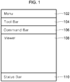
- FIG. 1 is a view showing a monitoring viewer of a HMI system in the related art.
- a monitoring viewer shown in FIG. 1 is displayed on a display device to provide a user with data for monitoring.
- the monitoring viewer consists of a control area including a menu bar 102, a tool bar 104, a command bar 106 and a status bar 110, and a view area including a viewer 108.
- the monitoring viewer shown in FIG. 1 is displayed on the display device when a user sends a request to run the monitoring viewer.
- a screen for displaying a variety of data items for monitoring is rendered in the viewer 108.
- the HMI system acquires screen data from a memory disposed inside or outside the HMI system and displays a monitoring screen in the viewer 108 based on the acquired screen data.
- the existing monitoring viewer includes only one viewer 108. Accordingly, when a user wants to obtain several monitoring information pieces, the user has to run a plurality of monitoring viewers like one shown in FIG. 1 . When a plurality of monitoring viewers is run, a user has to manage several viewers simultaneously, which is inconvenient. In addition, system resources of the HMI system are used too much, such that the overall performance and efficiency of the system can be lowered.
- a method for displaying a monitoring viewer includes, upon receiving a request to display a monitoring viewer from a user, acquiring screen data to be displayed in the monitoring viewer; displaying a control area of the monitoring viewer on a display; displaying a view area of the monitoring viewer on the display; and displaying a monitoring screen in the view area by using the screen data.
- the view area includes one or more details areas.
- a user can operate, monitor and control a HMI system more conveniently and efficiently.
- monitoring performance and efficiency of the HMI system can be increased.
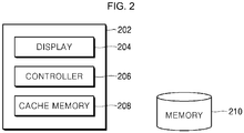
- FIG. 2 is a block diagram of a HMI system according to an exemplary embodiment of the present disclosure.
- a HMI system 202 includes a display 204 and a controller 206.
- the display 204 displays information for a user to operate, monitor and control the HMI system. According to an exemplary embodiment of the present disclosure, the display 204 may display a monitoring viewer shown in FIG. 4 .
- the controller 206 receives a request to display a monitoring viewer from a user and displays a monitoring viewer on the display 204 in response to the user's request.
- the controller 206 upon receiving a request to display a monitoring viewer from a user, acquires screen data to be displayed in the monitoring viewer. In addition, the controller 206 displays a control area and a view area of the monitoring viewer on the display. The controller 206 displays a monitoring screen in the view area by using the acquired screen data.
- the controller 206 may load priority screen data from a memory to store it in a cache memory 208 before a user sends a request to display a monitoring viewer.
- priority screen data refers to data that has to be processed in advance over other screen data. For example, a user may designate a monitoring screen that is frequently visited or is important as the priority screen data in advance.
- controller 206 may count processing time of each screen data and may set screen data whose counted processing time exceeds a predetermined reference processing time as the priority screen data.
- processing time refers to time taken for loading data or rendering.
- the reference processing time may be set arbitrarily by the user or the controller 206.
- such priority screen data is stored in the cache memory 208 before a user sends a request to display a monitoring viewer, so that the monitoring viewer can be displayed more quickly.
- the controller 206 may search the cache memory 208 for screen data to display the view area of the monitoring viewer.
- the priority screen data may be stored in the cache memory 208 as described above, the controller 206 may search the cache memory 208 first to acquire the priority screen data. After searching the cache memory 208, the controller 206 may configure screen data by using data acquired from the memory 210. For example, the controller 206 may serialize the data acquired from the memory 210 to create screen data, and may display the view area by using the created screen data.
- the view area may include one or more details areas.
- the one or more details areas include an active details area and inactive details areas.
- the active details area is the details area that is selected by the user and is currently activated on the display.
- the inactive details areas are the other details areas than the active details area.
- the update cycle of the active details area may be set to be shorter than that of the inactive details areas.
- the update cycle of an inactive details area may be set to be shorter as the screen displayed in the inactive details area is larger.
- the inactive details areas may not be updated until they are activated and may be updated as soon as they are activated.
- the HMI system 202 may further include a cache memory 208.
- the cache memory 208 reads and writes data faster than the memory 210.
- the priority screen data may be stored in the cache memory 208.
- the controller 206 searches the cache memory 208 first to acquire screen data, such that the monitoring viewer can be displayed faster.
- the memory 210 is a storage medium that stores a variety of types of data to be displayed in the monitoring viewer.
- image or text data for configuring screen data and other data for monitoring the HMI system may be stored.
- the HMI system 202 shown in FIG. 2 includes the cache memory 208 therein, the cache memory 208 may be disposed outside the HMI system 202 according to another exemplary embodiment.
- the memory 210 is disposed outside the HMI system 202 in FIG. 2 , the memory 210 may be disposed in the HMI system 202 according to another exemplary embodiment.
- FIG. 3 is a flow chart for illustrating a method for displaying a monitoring viewer of the HMI system according to an exemplary embodiment of the present disclosure.
- FIG. 4 is a diagram showing a configuration of a monitoring viewer according to an exemplary embodiment of the present disclosure.
- the controller 206 Upon receiving a request to display a monitoring viewer from a user, the controller 206 acquires screen data to be displayed in the monitoring viewer (step S302). To acquire screen data, the controller 206 may search the cache memory 208 first. As described above, priority screen data including at least one of screen data designated by the user in advance and screen data whose loading time exceeds a predetermined reference processing time may be stored in cache memory 208. If such priority screen data is stored in the cache memory 208, the controller 206 loads the priority screen data first to render a monitoring screen in the view area on the display.
- the controller 206 may acquire data for configuring screen data from the memory 210 and configure (serialize) screen data to be displayed in the view area by using the acquired data.
- the controller 206 may load screen data thus configured to render the monitoring screen in the view area on the display.
- the controller 206 may search for screen data based on a key value (e.g., a file name) of the screen data to be displayed in the monitoring viewer requested by the user.
- a key value e.g., a file name
- the controller 206 may load priority screen data from the memory to store it in the cache memory before step S302, i.e., before the user sends a request to display a monitoring viewer. For example, if the user designates a screen that the user prefers or visits frequently, the controller 206 may search the memory 210 for screen data corresponding to the designated screen and may store the found screen data in the cache memory 208 as the priority screen data. In addition, the controller 206 may count processing time of each screen data stored in the memory 210 and may store screen data whose counted processing time exceeds a predetermined reference processing time in the cache memory 208 as the priority screen data.
- FIG. 4 is a diagram showing a configuration of a monitoring viewer according to an exemplary embodiment of the present disclosure.
- the control area includes a menu bar 402, a tool bar 404, a command bar 406 and a status bar 414.
- the controller 206 displays a view area of the monitoring viewer on the display (step S306).
- the view area includes one or more details areas 408, 410, 412,...
- FIG. 3 illustrates the controller 206 displays the control area (step S304) first and then displays the view area (step S306)
- the controller 206 may display the view area first and then display the control area.
- the controller 206 displays monitoring screens in the view areas 408, 410, 412,... by using screen data.
- the controller 206 may acquire screen data corresponding to each of the view areas 408, 410, 412,... and may render the acquired screen data in each of the view area 408, 410, 412,... to display the monitoring screens.
- a method for displaying a monitoring viewer may include acquiring screen data to be displayed in the monitoring viewer upon receiving a request to display a monitoring viewer from a user (step S302), and displaying a monitoring screen in the view area of the monitoring viewer by using the acquired screen data (step S308).
- the view area of the monitoring viewer displayed by the method according to the exemplary embodiment of the present disclosure includes one or more details areas.
- a user runs only one monitoring viewer and creates a plurality of details areas in the viewer, such that a number of monitoring information pieces can be obtained simultaneously. Accordingly, the user can operate, monitor and control the HMI system more conveniently.
- the HMI system need not run a number of monitoring viewers, such that system resources are less used and thus the overall performance and efficiency of the system can be improved.
- the details areas included in the view area of the monitoring viewer displayed by the method according to the exemplary embodiment of the present disclosure may be divided into an active details area and inactive details areas.
- the active details area is the details area that is selected by the user and is currently activated on the display.
- the inactive details areas are the other details areas than the active details area.
- the details area 408 is an active details area, and the details areas 410, 412,... are inactive details areas.
- the user may switch one of the inactive details areas 410, 412, ... over to the active details area at any time while the user is using the monitoring viewer. At that time, the previous active details area 408 may be switched over to an inactive details area.
- the controller 206 may set the update cycle of the active details area to be different from the update cycles of the inactive details areas.
- the details areas 408, 410, 412,... of the view area shown in FIG. 4 a variety of data items for monitoring the HMI system are displayed, such as power consumption, temperature value, etc. Such data items are used by programs corresponding to the respective details areas 408, 410, 412,... and may be updated at certain cycles. Accordingly, each of the details areas 408, 410, 412,... has its own update cycle corresponding to the respective programs.
- the update cycle of the active details area 408 is set to be different from the update cycles of the inactive details areas 410, 412,....
- the update cycle of the active details area 408 may be set to be shorter than the update cycles of the inactive details areas 410, 412,....
- the actual update cycle of the inactive details areas may be set to 5 x y, where y is a natural number.
- the active details area 408 is updated at the original update cycle required by the program, whereas the inactive details areas 410, 412, ... are updated more slowly than the original update cycles. In this manner, the system resource used for updating the inactive details areas 410, 412,...can be reduced.
- the update cycles of the active details area 408 and the update cycles of the inactive details areas 410, 412,... may be arbitrarily set by the user, respectively.
- the controller 206 may be update the details area immediately. For example, if the user selects the inactive details area 410 to activate it while the monitoring viewer is display as shown in FIG. 4 , the controller 206 updates the inactive details area 410 immediately and switch it over to the active details area, irrespectively of the update cycle 5 x y set by the controller 206. Accordingly, the active details area 408 is switched over to the inactive details area.
- the controller 206 may set the update cycle of an inactive details area with a larger screen to be shorter.
- the controller 206 may not update the inactive details areas 410, 412,... until they are activated. For example, when the monitoring viewer is displayed as shown in FIG. 4 , the controller 206 may update only the active details area 408 at the original update cycle and may not update the inactive details areas 410, 412, .... When the user wants to select the inactive details area among the inactive details areas 410, 412, ... to active it, the controller 206 may update the selected details area 410 immediately and switch it over to the active details area. By doing so, the resource used for updating the inactive details areas 410, 412, ... can be further reduced, thereby improving the system performance.
- the controller 206 may increase the initially set update cycles of all of the details areas 408, 410, 412, ... or may not update all of the details areas at all until an external input is received.
- the external input may be a select signal received from the user.
- the resource used for updating all of the details areas 408, 410, 412, ... while the user is not using the HMI system may be reduced, thereby improving the system performance.
Landscapes
- Engineering & Computer Science (AREA)
- General Physics & Mathematics (AREA)
- Physics & Mathematics (AREA)
- Automation & Control Theory (AREA)
- Human Computer Interaction (AREA)
- Theoretical Computer Science (AREA)
- Computer Hardware Design (AREA)
- Quality & Reliability (AREA)
- Manufacturing & Machinery (AREA)
- General Engineering & Computer Science (AREA)
- Controls And Circuits For Display Device (AREA)
- User Interface Of Digital Computer (AREA)
- Testing And Monitoring For Control Systems (AREA)
- Programmable Controllers (AREA)
Abstract
Description
- The present disclosure relates to a method for displaying a monitoring viewer in a HMI system.
- A HMI (Human Machine Interface) system is used to provide users with graphical information in communications with a PLC (Programmable Logical Controller) used in factory automation. The HMI system is also connected to a camera or other media devices to provide operators with improved management service and displays graphical results of monitoring. The HMI system allows operators to monitor operation fields from a distant location and to observe accidents remotely. When an accident occurs, the scene at the current time and information before/after the accident can be stored and monitored in real-time.
- Such a HMI system employs a program for providing a user with a variety of information pieces for monitoring, e.g., a monitoring viewer. The user may check a variety of types of data for monitoring and the status of the overall system via the monitoring viewer provided on a display device and may make a command to the HMI system as desired.
-
FIG. 1 is a view showing a monitoring viewer of a HMI system in the related art. - In the HMI system in the related art, a monitoring viewer shown in
FIG. 1 is displayed on a display device to provide a user with data for monitoring. The monitoring viewer consists of a control area including amenu bar 102, atool bar 104, acommand bar 106 and astatus bar 110, and a view area including aviewer 108. - In the related art, the monitoring viewer shown in
FIG. 1 is displayed on the display device when a user sends a request to run the monitoring viewer. In particular, a screen for displaying a variety of data items for monitoring is rendered in theviewer 108. To this end, the HMI system acquires screen data from a memory disposed inside or outside the HMI system and displays a monitoring screen in theviewer 108 based on the acquired screen data. - As can be seen from
FIG. 1 , the existing monitoring viewer includes only oneviewer 108. Accordingly, when a user wants to obtain several monitoring information pieces, the user has to run a plurality of monitoring viewers like one shown inFIG. 1 . When a plurality of monitoring viewers is run, a user has to manage several viewers simultaneously, which is inconvenient. In addition, system resources of the HMI system are used too much, such that the overall performance and efficiency of the system can be lowered. - It is an aspect of the present disclosure to provide a method for displaying a monitoring viewer by which a user can operate, monitor and control a HMI system more conveniently and efficiently.
- It is another aspect of the present disclosure to provide a method for displaying a monitoring viewer by which monitoring performance and efficiency of the HMI system.
- Objects of the present disclosure are not limited to the above-described objects and other objects and advantages can be appreciated by those skilled in the art from the following descriptions. Further, it will be easily appreciated that the objects and advantages of the present disclosure can be practiced by means recited in the appended claims and a combination thereof.
- In accordance with one aspect of the present disclosure, a method for displaying a monitoring viewer includes, upon receiving a request to display a monitoring viewer from a user, acquiring screen data to be displayed in the monitoring viewer; displaying a control area of the monitoring viewer on a display; displaying a view area of the monitoring viewer on the display; and displaying a monitoring screen in the view area by using the screen data. The view area includes one or more details areas.
- According to an exemplary embodiment of the present disclosure, a user can operate, monitor and control a HMI system more conveniently and efficiently.
- In addition, according to an exemplary embodiment of the present disclosure, monitoring performance and efficiency of the HMI system can be increased.
-
-
FIG. 1 is a view showing a monitoring viewer of a HMI system in the related art; -
FIG. 2 is a block diagram of a HMI system according to an exemplary embodiment of the present disclosure; -
FIG. 3 is a flow chart for illustrating a method for displaying a monitoring viewer of the HMI system according to an exemplary embodiment of the present disclosure; and -
FIG. 4 is a diagram showing a configuration of a monitoring viewer according to an exemplary embodiment of the present disclosure. - The above objects, features and advantages will become apparent from the detailed description with reference to the accompanying drawings. Embodiments are described in sufficient detail to enable those skilled in the art in the art to easily practice the technical idea of the present disclosure. Detailed disclosures of well known functions or configurations may be omitted in order not to unnecessarily obscure the gist of the present disclosure. Hereinafter, embodiments of the present disclosure will be described in detail with reference to the accompanying drawings. Throughout the drawings, like reference numerals refer to like elements.
-
FIG. 2 is a block diagram of a HMI system according to an exemplary embodiment of the present disclosure. - Referring to
FIG. 2 , aHMI system 202 according to an exemplary embodiment of the present disclosure includes adisplay 204 and acontroller 206. - The
display 204 displays information for a user to operate, monitor and control the HMI system. According to an exemplary embodiment of the present disclosure, thedisplay 204 may display a monitoring viewer shown inFIG. 4 . - The
controller 206 receives a request to display a monitoring viewer from a user and displays a monitoring viewer on thedisplay 204 in response to the user's request. - According to an exemplary embodiment of the present disclosure, upon receiving a request to display a monitoring viewer from a user, the
controller 206 acquires screen data to be displayed in the monitoring viewer. In addition, thecontroller 206 displays a control area and a view area of the monitoring viewer on the display. Thecontroller 206 displays a monitoring screen in the view area by using the acquired screen data. - According to an exemplary embodiment of the present disclosure, the
controller 206 may load priority screen data from a memory to store it in acache memory 208 before a user sends a request to display a monitoring viewer. As used herein, "priority screen data" refers to data that has to be processed in advance over other screen data. For example, a user may designate a monitoring screen that is frequently visited or is important as the priority screen data in advance. - In addition, the
controller 206 may count processing time of each screen data and may set screen data whose counted processing time exceeds a predetermined reference processing time as the priority screen data. As used herein, "processing time" refers to time taken for loading data or rendering. - In addition, the reference processing time may be set arbitrarily by the user or the
controller 206. According to the exemplary embodiment of the present disclosure, such priority screen data is stored in thecache memory 208 before a user sends a request to display a monitoring viewer, so that the monitoring viewer can be displayed more quickly. - According to an exemplary embodiment of the present disclosure, the
controller 206 may search thecache memory 208 for screen data to display the view area of the monitoring viewer. As the priority screen data may be stored in thecache memory 208 as described above, thecontroller 206 may search thecache memory 208 first to acquire the priority screen data. After searching thecache memory 208, thecontroller 206 may configure screen data by using data acquired from thememory 210. For example, thecontroller 206 may serialize the data acquired from thememory 210 to create screen data, and may display the view area by using the created screen data. - According to an exemplary embodiment of the present disclosure, the view area may include one or more details areas. The one or more details areas include an active details area and inactive details areas. The active details area is the details area that is selected by the user and is currently activated on the display. The inactive details areas are the other details areas than the active details area.
- According to an exemplary embodiment of the present disclosure, the update cycle of the active details area may be set to be shorter than that of the inactive details areas. According to an exemplary embodiment of the present disclosure, when a user activates one of the inactive details areas, it may be updated immediately irrespectively of the update cycle. According to an exemplary embodiment of the present disclosure, the update cycle of an inactive details area may be set to be shorter as the screen displayed in the inactive details area is larger. According to an exemplary embodiment of the present disclosure, the inactive details areas may not be updated until they are activated and may be updated as soon as they are activated.
- Referring back to
FIG. 2 , theHMI system 202 according to an exemplary embodiment of the present disclosure may further include acache memory 208. Thecache memory 208 reads and writes data faster than thememory 210. The priority screen data may be stored in thecache memory 208. When displaying the monitoring viewer, thecontroller 206 searches thecache memory 208 first to acquire screen data, such that the monitoring viewer can be displayed faster. - The
memory 210 is a storage medium that stores a variety of types of data to be displayed in the monitoring viewer. In thememory 210, image or text data for configuring screen data and other data for monitoring the HMI system may be stored. - Although the
HMI system 202 shown inFIG. 2 includes thecache memory 208 therein, thecache memory 208 may be disposed outside theHMI system 202 according to another exemplary embodiment. In addition, although thememory 210 is disposed outside theHMI system 202 inFIG. 2 , thememory 210 may be disposed in theHMI system 202 according to another exemplary embodiment. -
FIG. 3 is a flow chart for illustrating a method for displaying a monitoring viewer of the HMI system according to an exemplary embodiment of the present disclosure.FIG. 4 is a diagram showing a configuration of a monitoring viewer according to an exemplary embodiment of the present disclosure. - Hereinafter, a method for displaying a monitoring viewer of a HMI system according to an exemplary embodiment of the present disclosure will be described in detail with reference to
FIGS. 2 and4 . - Upon receiving a request to display a monitoring viewer from a user, the
controller 206 acquires screen data to be displayed in the monitoring viewer (step S302). To acquire screen data, thecontroller 206 may search thecache memory 208 first. As described above, priority screen data including at least one of screen data designated by the user in advance and screen data whose loading time exceeds a predetermined reference processing time may be stored incache memory 208. If such priority screen data is stored in thecache memory 208, thecontroller 206 loads the priority screen data first to render a monitoring screen in the view area on the display. - After searching the
cache memory 208, thecontroller 206 may acquire data for configuring screen data from thememory 210 and configure (serialize) screen data to be displayed in the view area by using the acquired data. Thecontroller 206 may load screen data thus configured to render the monitoring screen in the view area on the display. - When searching the
cache memory 208 or thememory 210, thecontroller 206 may search for screen data based on a key value (e.g., a file name) of the screen data to be displayed in the monitoring viewer requested by the user. - Although not shown in
FIG. 3 , thecontroller 206 may load priority screen data from the memory to store it in the cache memory before step S302, i.e., before the user sends a request to display a monitoring viewer. For example, if the user designates a screen that the user prefers or visits frequently, thecontroller 206 may search thememory 210 for screen data corresponding to the designated screen and may store the found screen data in thecache memory 208 as the priority screen data. In addition, thecontroller 206 may count processing time of each screen data stored in thememory 210 and may store screen data whose counted processing time exceeds a predetermined reference processing time in thecache memory 208 as the priority screen data. - Subsequently, the
controller 206 displays a controller area of a monitoring viewer on the display (step S304).FIG. 4 is a diagram showing a configuration of a monitoring viewer according to an exemplary embodiment of the present disclosure. InFIG. 4 , the control area includes amenu bar 402, atool bar 404, acommand bar 406 and astatus bar 414. - Subsequently, the
controller 206 displays a view area of the monitoring viewer on the display (step S306). InFIG. 4 , the view area includes one ormore details areas - Although
FIG. 3 illustrates thecontroller 206 displays the control area (step S304) first and then displays the view area (step S306), thecontroller 206 according to another exemplary embodiment of the present disclosure may display the view area first and then display the control area. - Subsequently, the
controller 206 displays monitoring screens in theview areas controller 206 may acquire screen data corresponding to each of theview areas view area - According to another exemplary embodiment of the present disclosure, a method for displaying a monitoring viewer may include acquiring screen data to be displayed in the monitoring viewer upon receiving a request to display a monitoring viewer from a user (step S302), and displaying a monitoring screen in the view area of the monitoring viewer by using the acquired screen data (step S308).
- As shown in
FIG. 4 , the view area of the monitoring viewer displayed by the method according to the exemplary embodiment of the present disclosure includes one or more details areas. According to an exemplary embodiment of the present disclosure, a user runs only one monitoring viewer and creates a plurality of details areas in the viewer, such that a number of monitoring information pieces can be obtained simultaneously. Accordingly, the user can operate, monitor and control the HMI system more conveniently. In addition, the HMI system need not run a number of monitoring viewers, such that system resources are less used and thus the overall performance and efficiency of the system can be improved. - Referring back to
FIG. 4 , the details areas included in the view area of the monitoring viewer displayed by the method according to the exemplary embodiment of the present disclosure may be divided into an active details area and inactive details areas. The active details area is the details area that is selected by the user and is currently activated on the display. The inactive details areas are the other details areas than the active details area. InFIG. 4 , thedetails area 408 is an active details area, and thedetails areas inactive details areas active details area 408 may be switched over to an inactive details area. - Although not shown in
FIG. 3 , according to an exemplary embodiment of the present disclosure, thecontroller 206 may set the update cycle of the active details area to be different from the update cycles of the inactive details areas. In each of thedetails areas FIG. 4 , a variety of data items for monitoring the HMI system are displayed, such as power consumption, temperature value, etc. Such data items are used by programs corresponding to therespective details areas details areas - In the view area with the
details areas FIG. 4 , if all of thedetails areas active details area 408 is set to be different from the update cycles of theinactive details areas - According to an exemplary embodiment of the present disclosure, the update cycle of the
active details area 408 may be set to be shorter than the update cycles of theinactive details areas inactive details area 410 is five seconds, the actual update cycle of the inactive details areas may be set to 5 x y, where y is a natural number. As a result, theactive details area 408 is updated at the original update cycle required by the program, whereas theinactive details areas inactive details areas - According to an exemplary embodiment of the present disclosure, the update cycles of the
active details area 408 and the update cycles of theinactive details areas - According to an exemplary embodiment of the present disclosure, when a user activates one of the
inactive details areas controller 206 may be update the details area immediately. For example, if the user selects theinactive details area 410 to activate it while the monitoring viewer is display as shown inFIG. 4 , thecontroller 206 updates theinactive details area 410 immediately and switch it over to the active details area, irrespectively of the update cycle 5 x y set by thecontroller 206. Accordingly, theactive details area 408 is switched over to the inactive details area. - According to an exemplary embodiment of the present disclosure, the
controller 206 may set the update cycle of an inactive details area with a larger screen to be shorter. The larger the size of the screen displayed in an inactive details area is, the longer time it takes to update the screen. By doing so, the update delay taken when the user switches the inactive details area over to the active details area can be reduced. - According to an exemplary embodiment of the present disclosure, the
controller 206 may not update theinactive details areas FIG. 4 , thecontroller 206 may update only theactive details area 408 at the original update cycle and may not update theinactive details areas inactive details areas controller 206 may update the selecteddetails area 410 immediately and switch it over to the active details area. By doing so, the resource used for updating theinactive details areas - According to another exemplary embodiment of the present disclosure, if no external input is received for a predetermined input time period, the
controller 206 may increase the initially set update cycles of all of thedetails areas - In this manner, the resource used for updating all of the
details areas - The present disclosure described above may be variously substituted, altered, and modified by those skilled in the art to which the present invention pertains without departing from the scope and sprit of the present disclosure. Therefore, the present disclosure is not limited to the above-mentioned exemplary embodiments and the accompanying drawings.
Claims (8)
- A method for displaying a monitoring viewer in a HMI system (220), the method comprising:upon receiving a request to display the monitoring viewer from a user, acquiring screen data to be displayed in the monitoring viewer; anddisplaying a monitoring screen in a view area of the monitoring viewer by using the screen data, whereinthe view area comprises one or more details areas,the one or more details areas comprise an active details area and inactive details areas,an update cycle of the active details area is different from update cycles of the inactive details areas, andthe update cycle of each of the inactive details areas are set to be shorter as a size of a screen displayed therein is larger.
- The method of claim 1, further comprising:loading priority screen data from a memory (210) to store it in a cache memory (208) before the request is input.
- The method of claim 2, wherein the priority screen data comprises screen data designated by the user in advance and/or screen data whose processing time exceeds a predetermined reference processing time.
- The method of claim 1, wherein the acquiring screen data to be displayed in the monitoring viewer comprises:searching the cache memory (208) to acquire the screen data; andconfiguring the screen data by using data acquired from the memory (210).
- The method of claim 1, wherein the update cycle of the active details area is set to be shorter than the update cycles of the inactive details areas.
- The method of claim 1, wherein when the user activates one of the inactive details areas, it is updated immediately.
- The method of claim 1, wherein the inactive details areas are not updated until they are activated, and each of the inactive details areas is updated as soon as it is activated.
- The method of claim 1, further comprising:displaying a control area of the monitoring viewer on a display; anddisplaying the view area of the monitoring viewer on the display.
Applications Claiming Priority (1)
| Application Number | Priority Date | Filing Date | Title |
|---|---|---|---|
| KR1020160036211A KR101873093B1 (en) | 2016-03-25 | 2016-03-25 | Method for displaying monitoring viewer in hmi system |
Publications (2)
| Publication Number | Publication Date |
|---|---|
| EP3223091A1 true EP3223091A1 (en) | 2017-09-27 |
| EP3223091B1 EP3223091B1 (en) | 2018-08-22 |
Family
ID=57794019
Family Applications (1)
| Application Number | Title | Priority Date | Filing Date |
|---|---|---|---|
| EP16199051.0A Not-in-force EP3223091B1 (en) | 2016-03-25 | 2016-11-16 | Method for displaying monitoring viewer in hmi system |
Country Status (6)
| Country | Link |
|---|---|
| US (1) | US10109259B2 (en) |
| EP (1) | EP3223091B1 (en) |
| JP (1) | JP6312780B2 (en) |
| KR (1) | KR101873093B1 (en) |
| CN (1) | CN107229257B (en) |
| ES (1) | ES2692021T3 (en) |
Families Citing this family (4)
| Publication number | Priority date | Publication date | Assignee | Title |
|---|---|---|---|---|
| CN107977201B (en) * | 2017-11-15 | 2021-07-16 | 上海电科智能系统股份有限公司 | Automatic generation method of comprehensive monitoring HMI |
| KR102534295B1 (en) | 2018-05-29 | 2023-05-17 | 엘에스일렉트릭(주) | Hmi device and method for outputting data thereof |
| JP6724960B2 (en) * | 2018-09-14 | 2020-07-15 | 株式会社安川電機 | Resource monitoring system, resource monitoring method, and program |
| JPWO2025013295A1 (en) * | 2023-07-13 | 2025-01-16 |
Citations (1)
| Publication number | Priority date | Publication date | Assignee | Title |
|---|---|---|---|---|
| WO2011091271A1 (en) * | 2010-01-22 | 2011-07-28 | Ge Intelligent Platforms, Inc. | Global synchronization of time in graphical displays of a human machine interface |
Family Cites Families (28)
| Publication number | Priority date | Publication date | Assignee | Title |
|---|---|---|---|---|
| JPH02110627A (en) * | 1988-10-19 | 1990-04-23 | Hitachi Ltd | Displaying method for multi-window picture |
| US5745386A (en) * | 1995-09-25 | 1998-04-28 | International Business Machines Corporation | Timing diagram method for inputting logic design parameters to build a testcase for the logic diagram |
| JPH1020928A (en) | 1996-07-04 | 1998-01-23 | Mitsubishi Electric Corp | Multi-window display device |
| JPH10293609A (en) * | 1997-04-18 | 1998-11-04 | Komatsu Ltd | Controller operation system |
| JPH11238027A (en) | 1998-02-24 | 1999-08-31 | Hitachi Ltd | Screen updating method and screen updating terminal device |
| JP2004045748A (en) * | 2002-07-11 | 2004-02-12 | Sharp Corp | Display device and display method |
| JP2004133581A (en) | 2002-10-09 | 2004-04-30 | Toshiba Corp | Monitoring and control system |
| JP2005100027A (en) | 2003-09-24 | 2005-04-14 | Fuji Electric Fa Components & Systems Co Ltd | The failure information display device of the programmable controller has a content that is divided into detailed information about the relevant failure according to user-defined attributes in the failure details display section, each time this attribute is selected. A fault information display device for a programmable controller, which is displayed on the screen. |
| KR20060000732A (en) | 2004-06-29 | 2006-01-06 | 엔에이치엔(주) | Refresh method and system |
| US7774366B2 (en) | 2005-03-08 | 2010-08-10 | Salesforce.Com, Inc. | Systems and methods for implementing multi-application tabs and tab sets |
| JP2007213499A (en) * | 2006-02-13 | 2007-08-23 | Toyota Motor Corp | Design apparatus, design program, and design method |
| US7729630B2 (en) | 2007-01-24 | 2010-06-01 | Kabushiki Kaisha Toshiba | System and method for generating a user customizable default user interface for a document processing device |
| JP2009094895A (en) * | 2007-10-10 | 2009-04-30 | Olympus Corp | Image signal processor and color conversion processing method |
| US20090287559A1 (en) * | 2007-12-20 | 2009-11-19 | Michael Chen | TabTab |
| JP5388496B2 (en) | 2008-07-22 | 2014-01-15 | キヤノン株式会社 | Image display control device, image display control method, and program |
| JP5083629B2 (en) | 2009-01-13 | 2012-11-28 | 横河電機株式会社 | Status display device |
| US20100205556A1 (en) * | 2009-02-10 | 2010-08-12 | Alfa Laval Corporate Ab | Human machine interface navigation tool |
| JP5294924B2 (en) * | 2009-03-02 | 2013-09-18 | キヤノン株式会社 | Information processing apparatus, control method therefor, and program |
| US8380703B2 (en) * | 2010-07-26 | 2013-02-19 | International Business Machines Corporation | Feedback loop between a query optimizer and a cache manager |
| WO2012086049A1 (en) | 2010-12-24 | 2012-06-28 | 三菱電機株式会社 | Screen creation system for programmable indicator |
| JP5755125B2 (en) * | 2011-12-07 | 2015-07-29 | 三菱電機株式会社 | Web monitoring and control device |
| US8914594B2 (en) * | 2011-12-22 | 2014-12-16 | Sandisk Technologies Inc. | Systems and methods of loading data from a non-volatile memory to a volatile memory |
| WO2013189538A1 (en) * | 2012-06-20 | 2013-12-27 | Maquet Critical Care Ab | A breathing apparatus having a display with user selectable background |
| US8965462B2 (en) * | 2012-07-25 | 2015-02-24 | International Business Machines Corporation | Persistent display of priority information on a portable electronic device |
| KR20140014895A (en) * | 2012-07-27 | 2014-02-06 | 삼성전자주식회사 | Method and apparatus for saving battery of portable terminal |
| JP6423348B2 (en) * | 2012-10-08 | 2018-11-14 | フィッシャー−ローズマウント システムズ,インコーポレイテッド | Dynamically reusable class |
| JP2014206939A (en) | 2013-04-15 | 2014-10-30 | 株式会社安川電機 | Controller, control device, device control system, computer program and computer readable information storage medium |
| JP6253894B2 (en) * | 2013-04-18 | 2017-12-27 | シャープ株式会社 | Control device, display device, and control method |
-
2016
- 2016-03-25 KR KR1020160036211A patent/KR101873093B1/en not_active Expired - Fee Related
- 2016-11-16 ES ES16199051.0T patent/ES2692021T3/en active Active
- 2016-11-16 EP EP16199051.0A patent/EP3223091B1/en not_active Not-in-force
- 2016-11-18 US US15/355,864 patent/US10109259B2/en not_active Expired - Fee Related
- 2016-11-22 JP JP2016226576A patent/JP6312780B2/en active Active
- 2016-11-23 CN CN201611038409.8A patent/CN107229257B/en not_active Expired - Fee Related
Patent Citations (1)
| Publication number | Priority date | Publication date | Assignee | Title |
|---|---|---|---|---|
| WO2011091271A1 (en) * | 2010-01-22 | 2011-07-28 | Ge Intelligent Platforms, Inc. | Global synchronization of time in graphical displays of a human machine interface |
Non-Patent Citations (1)
| Title |
|---|
| DIGITAL ELECTRONIC CORPORATION: "GP-Viewer EX Operation Manual", 30 June 2008 (2008-06-30), pages 1 - 67, XP055366090, Retrieved from the Internet <URL:https://www.hmisource.com/otasuke/files/manual/proserver/viewer_v11/viewer.pdf> [retrieved on 20170420] * |
Also Published As
| Publication number | Publication date |
|---|---|
| ES2692021T3 (en) | 2018-11-29 |
| US10109259B2 (en) | 2018-10-23 |
| CN107229257A (en) | 2017-10-03 |
| EP3223091B1 (en) | 2018-08-22 |
| CN107229257B (en) | 2020-01-24 |
| US20170278487A1 (en) | 2017-09-28 |
| KR20170111223A (en) | 2017-10-12 |
| KR101873093B1 (en) | 2018-06-29 |
| JP2017173791A (en) | 2017-09-28 |
| JP6312780B2 (en) | 2018-04-18 |
Similar Documents
| Publication | Publication Date | Title |
|---|---|---|
| US10109259B2 (en) | Method for displaying monitoring viewer in HMI system | |
| EP2966617B1 (en) | System comprising image data generating device and portable terminal device | |
| US10838390B2 (en) | Program creation support apparatus, control method for program creation support apparatus, and control program for program creation support apparatus | |
| CN112419693A (en) | Device control method, device, display device and computer readable storage medium | |
| JP5077826B2 (en) | Plant information display device and plant information display method | |
| CN104252354A (en) | Method and device for refreshing data list of intelligent terminal | |
| CN110874085A (en) | Numerical controller | |
| KR101759593B1 (en) | Central control apparatus for controlling facilities and operation method thereof | |
| KR101083184B1 (en) | Screen transition control device | |
| CN106790424B (en) | Timing control method, client, server and timing control system | |
| US9921728B2 (en) | Service providing device, and method of providing a user interface | |
| JP4723960B2 (en) | Monitoring system and control device therefor | |
| US10782982B2 (en) | Information processing apparatus and system, and method and recording medium for generating user interface | |
| CN105653143B (en) | Processing method of application program operation interface and mobile terminal for realizing method | |
| KR101916771B1 (en) | Method for managing a monitoring apparatus | |
| JP6474610B2 (en) | Programmable display | |
| CN109634943B (en) | Air conditioner data transmission method and device for screening data and computer equipment | |
| KR20190135146A (en) | Node analysis method and apparauts thereof | |
| JP5390424B2 (en) | Plant monitoring device | |
| CN113836216A (en) | Data display method, device, storage medium and electronic device | |
| KR101531261B1 (en) | Apparatus and method for providing monitoring information | |
| EP3582113A1 (en) | Graphical representation of an industrial system for efficiently searching, displaying and managing devices of the industrial system | |
| CN108170390B (en) | Interaction method and system for switching display by remote control | |
| CN117255185A (en) | Method, device, equipment and storage medium for acquiring camera image | |
| KR101978786B1 (en) | Data retrieval method and apparatus thereof |
Legal Events
| Date | Code | Title | Description |
|---|---|---|---|
| PUAI | Public reference made under article 153(3) epc to a published international application that has entered the european phase |
Free format text: ORIGINAL CODE: 0009012 |
|
| STAA | Information on the status of an ep patent application or granted ep patent |
Free format text: STATUS: THE APPLICATION HAS BEEN PUBLISHED |
|
| AK | Designated contracting states |
Kind code of ref document: A1 Designated state(s): AL AT BE BG CH CY CZ DE DK EE ES FI FR GB GR HR HU IE IS IT LI LT LU LV MC MK MT NL NO PL PT RO RS SE SI SK SM TR |
|
| AX | Request for extension of the european patent |
Extension state: BA ME |
|
| STAA | Information on the status of an ep patent application or granted ep patent |
Free format text: STATUS: REQUEST FOR EXAMINATION WAS MADE |
|
| 17P | Request for examination filed |
Effective date: 20180323 |
|
| RBV | Designated contracting states (corrected) |
Designated state(s): AL AT BE BG CH CY CZ DE DK EE ES FI FR GB GR HR HU IE IS IT LI LT LU LV MC MK MT NL NO PL PT RO RS SE SI SK SM TR |
|
| GRAP | Despatch of communication of intention to grant a patent |
Free format text: ORIGINAL CODE: EPIDOSNIGR1 |
|
| STAA | Information on the status of an ep patent application or granted ep patent |
Free format text: STATUS: GRANT OF PATENT IS INTENDED |
|
| INTG | Intention to grant announced |
Effective date: 20180508 |
|
| GRAS | Grant fee paid |
Free format text: ORIGINAL CODE: EPIDOSNIGR3 |
|
| GRAA | (expected) grant |
Free format text: ORIGINAL CODE: 0009210 |
|
| STAA | Information on the status of an ep patent application or granted ep patent |
Free format text: STATUS: THE PATENT HAS BEEN GRANTED |
|
| AK | Designated contracting states |
Kind code of ref document: B1 Designated state(s): AL AT BE BG CH CY CZ DE DK EE ES FI FR GB GR HR HU IE IS IT LI LT LU LV MC MK MT NL NO PL PT RO RS SE SI SK SM TR |
|
| REG | Reference to a national code |
Ref country code: GB Ref legal event code: FG4D |
|
| REG | Reference to a national code |
Ref country code: CH Ref legal event code: EP |
|
| REG | Reference to a national code |
Ref country code: AT Ref legal event code: REF Ref document number: 1033192 Country of ref document: AT Kind code of ref document: T Effective date: 20180915 |
|
| REG | Reference to a national code |
Ref country code: IE Ref legal event code: FG4D |
|
| REG | Reference to a national code |
Ref country code: DE Ref legal event code: R096 Ref document number: 602016004973 Country of ref document: DE |
|
| REG | Reference to a national code |
Ref country code: ES Ref legal event code: FG2A Ref document number: 2692021 Country of ref document: ES Kind code of ref document: T3 Effective date: 20181129 |
|
| REG | Reference to a national code |
Ref country code: NL Ref legal event code: MP Effective date: 20180822 |
|
| REG | Reference to a national code |
Ref country code: LT Ref legal event code: MG4D |
|
| PG25 | Lapsed in a contracting state [announced via postgrant information from national office to epo] |
Ref country code: IS Free format text: LAPSE BECAUSE OF FAILURE TO SUBMIT A TRANSLATION OF THE DESCRIPTION OR TO PAY THE FEE WITHIN THE PRESCRIBED TIME-LIMIT Effective date: 20181222 Ref country code: NL Free format text: LAPSE BECAUSE OF FAILURE TO SUBMIT A TRANSLATION OF THE DESCRIPTION OR TO PAY THE FEE WITHIN THE PRESCRIBED TIME-LIMIT Effective date: 20180822 Ref country code: BG Free format text: LAPSE BECAUSE OF FAILURE TO SUBMIT A TRANSLATION OF THE DESCRIPTION OR TO PAY THE FEE WITHIN THE PRESCRIBED TIME-LIMIT Effective date: 20181122 Ref country code: LT Free format text: LAPSE BECAUSE OF FAILURE TO SUBMIT A TRANSLATION OF THE DESCRIPTION OR TO PAY THE FEE WITHIN THE PRESCRIBED TIME-LIMIT Effective date: 20180822 Ref country code: GR Free format text: LAPSE BECAUSE OF FAILURE TO SUBMIT A TRANSLATION OF THE DESCRIPTION OR TO PAY THE FEE WITHIN THE PRESCRIBED TIME-LIMIT Effective date: 20181123 Ref country code: SE Free format text: LAPSE BECAUSE OF FAILURE TO SUBMIT A TRANSLATION OF THE DESCRIPTION OR TO PAY THE FEE WITHIN THE PRESCRIBED TIME-LIMIT Effective date: 20180822 Ref country code: NO Free format text: LAPSE BECAUSE OF FAILURE TO SUBMIT A TRANSLATION OF THE DESCRIPTION OR TO PAY THE FEE WITHIN THE PRESCRIBED TIME-LIMIT Effective date: 20181122 Ref country code: RS Free format text: LAPSE BECAUSE OF FAILURE TO SUBMIT A TRANSLATION OF THE DESCRIPTION OR TO PAY THE FEE WITHIN THE PRESCRIBED TIME-LIMIT Effective date: 20180822 Ref country code: FI Free format text: LAPSE BECAUSE OF FAILURE TO SUBMIT A TRANSLATION OF THE DESCRIPTION OR TO PAY THE FEE WITHIN THE PRESCRIBED TIME-LIMIT Effective date: 20180822 |
|
| REG | Reference to a national code |
Ref country code: AT Ref legal event code: MK05 Ref document number: 1033192 Country of ref document: AT Kind code of ref document: T Effective date: 20180822 |
|
| PG25 | Lapsed in a contracting state [announced via postgrant information from national office to epo] |
Ref country code: HR Free format text: LAPSE BECAUSE OF FAILURE TO SUBMIT A TRANSLATION OF THE DESCRIPTION OR TO PAY THE FEE WITHIN THE PRESCRIBED TIME-LIMIT Effective date: 20180822 Ref country code: AL Free format text: LAPSE BECAUSE OF FAILURE TO SUBMIT A TRANSLATION OF THE DESCRIPTION OR TO PAY THE FEE WITHIN THE PRESCRIBED TIME-LIMIT Effective date: 20180822 Ref country code: LV Free format text: LAPSE BECAUSE OF FAILURE TO SUBMIT A TRANSLATION OF THE DESCRIPTION OR TO PAY THE FEE WITHIN THE PRESCRIBED TIME-LIMIT Effective date: 20180822 |
|
| PG25 | Lapsed in a contracting state [announced via postgrant information from national office to epo] |
Ref country code: CZ Free format text: LAPSE BECAUSE OF FAILURE TO SUBMIT A TRANSLATION OF THE DESCRIPTION OR TO PAY THE FEE WITHIN THE PRESCRIBED TIME-LIMIT Effective date: 20180822 Ref country code: RO Free format text: LAPSE BECAUSE OF FAILURE TO SUBMIT A TRANSLATION OF THE DESCRIPTION OR TO PAY THE FEE WITHIN THE PRESCRIBED TIME-LIMIT Effective date: 20180822 Ref country code: AT Free format text: LAPSE BECAUSE OF FAILURE TO SUBMIT A TRANSLATION OF THE DESCRIPTION OR TO PAY THE FEE WITHIN THE PRESCRIBED TIME-LIMIT Effective date: 20180822 Ref country code: PL Free format text: LAPSE BECAUSE OF FAILURE TO SUBMIT A TRANSLATION OF THE DESCRIPTION OR TO PAY THE FEE WITHIN THE PRESCRIBED TIME-LIMIT Effective date: 20180822 Ref country code: EE Free format text: LAPSE BECAUSE OF FAILURE TO SUBMIT A TRANSLATION OF THE DESCRIPTION OR TO PAY THE FEE WITHIN THE PRESCRIBED TIME-LIMIT Effective date: 20180822 |
|
| REG | Reference to a national code |
Ref country code: DE Ref legal event code: R097 Ref document number: 602016004973 Country of ref document: DE |
|
| PG25 | Lapsed in a contracting state [announced via postgrant information from national office to epo] |
Ref country code: SM Free format text: LAPSE BECAUSE OF FAILURE TO SUBMIT A TRANSLATION OF THE DESCRIPTION OR TO PAY THE FEE WITHIN THE PRESCRIBED TIME-LIMIT Effective date: 20180822 Ref country code: SK Free format text: LAPSE BECAUSE OF FAILURE TO SUBMIT A TRANSLATION OF THE DESCRIPTION OR TO PAY THE FEE WITHIN THE PRESCRIBED TIME-LIMIT Effective date: 20180822 Ref country code: DK Free format text: LAPSE BECAUSE OF FAILURE TO SUBMIT A TRANSLATION OF THE DESCRIPTION OR TO PAY THE FEE WITHIN THE PRESCRIBED TIME-LIMIT Effective date: 20180822 |
|
| PLBE | No opposition filed within time limit |
Free format text: ORIGINAL CODE: 0009261 |
|
| STAA | Information on the status of an ep patent application or granted ep patent |
Free format text: STATUS: NO OPPOSITION FILED WITHIN TIME LIMIT |
|
| 26N | No opposition filed |
Effective date: 20190523 |
|
| PG25 | Lapsed in a contracting state [announced via postgrant information from national office to epo] |
Ref country code: MC Free format text: LAPSE BECAUSE OF FAILURE TO SUBMIT A TRANSLATION OF THE DESCRIPTION OR TO PAY THE FEE WITHIN THE PRESCRIBED TIME-LIMIT Effective date: 20180822 Ref country code: LU Free format text: LAPSE BECAUSE OF NON-PAYMENT OF DUE FEES Effective date: 20181116 |
|
| REG | Reference to a national code |
Ref country code: BE Ref legal event code: MM Effective date: 20181130 |
|
| REG | Reference to a national code |
Ref country code: IE Ref legal event code: MM4A |
|
| PG25 | Lapsed in a contracting state [announced via postgrant information from national office to epo] |
Ref country code: SI Free format text: LAPSE BECAUSE OF FAILURE TO SUBMIT A TRANSLATION OF THE DESCRIPTION OR TO PAY THE FEE WITHIN THE PRESCRIBED TIME-LIMIT Effective date: 20180822 |
|
| PG25 | Lapsed in a contracting state [announced via postgrant information from national office to epo] |
Ref country code: IE Free format text: LAPSE BECAUSE OF NON-PAYMENT OF DUE FEES Effective date: 20181116 |
|
| PGFP | Annual fee paid to national office [announced via postgrant information from national office to epo] |
Ref country code: FR Payment date: 20190906 Year of fee payment: 4 |
|
| PG25 | Lapsed in a contracting state [announced via postgrant information from national office to epo] |
Ref country code: BE Free format text: LAPSE BECAUSE OF NON-PAYMENT OF DUE FEES Effective date: 20181130 |
|
| PG25 | Lapsed in a contracting state [announced via postgrant information from national office to epo] |
Ref country code: MT Free format text: LAPSE BECAUSE OF NON-PAYMENT OF DUE FEES Effective date: 20181116 |
|
| PGFP | Annual fee paid to national office [announced via postgrant information from national office to epo] |
Ref country code: DE Payment date: 20190905 Year of fee payment: 4 |
|
| PGFP | Annual fee paid to national office [announced via postgrant information from national office to epo] |
Ref country code: ES Payment date: 20191203 Year of fee payment: 4 Ref country code: IT Payment date: 20191130 Year of fee payment: 4 |
|
| PG25 | Lapsed in a contracting state [announced via postgrant information from national office to epo] |
Ref country code: TR Free format text: LAPSE BECAUSE OF FAILURE TO SUBMIT A TRANSLATION OF THE DESCRIPTION OR TO PAY THE FEE WITHIN THE PRESCRIBED TIME-LIMIT Effective date: 20180822 |
|
| PG25 | Lapsed in a contracting state [announced via postgrant information from national office to epo] |
Ref country code: PT Free format text: LAPSE BECAUSE OF FAILURE TO SUBMIT A TRANSLATION OF THE DESCRIPTION OR TO PAY THE FEE WITHIN THE PRESCRIBED TIME-LIMIT Effective date: 20180822 |
|
| PG25 | Lapsed in a contracting state [announced via postgrant information from national office to epo] |
Ref country code: MK Free format text: LAPSE BECAUSE OF NON-PAYMENT OF DUE FEES Effective date: 20180822 Ref country code: HU Free format text: LAPSE BECAUSE OF FAILURE TO SUBMIT A TRANSLATION OF THE DESCRIPTION OR TO PAY THE FEE WITHIN THE PRESCRIBED TIME-LIMIT; INVALID AB INITIO Effective date: 20161116 Ref country code: CY Free format text: LAPSE BECAUSE OF FAILURE TO SUBMIT A TRANSLATION OF THE DESCRIPTION OR TO PAY THE FEE WITHIN THE PRESCRIBED TIME-LIMIT Effective date: 20180822 |
|
| REG | Reference to a national code |
Ref country code: CH Ref legal event code: PL |
|
| PG25 | Lapsed in a contracting state [announced via postgrant information from national office to epo] |
Ref country code: CH Free format text: LAPSE BECAUSE OF NON-PAYMENT OF DUE FEES Effective date: 20191130 Ref country code: LI Free format text: LAPSE BECAUSE OF NON-PAYMENT OF DUE FEES Effective date: 20191130 |
|
| REG | Reference to a national code |
Ref country code: DE Ref legal event code: R119 Ref document number: 602016004973 Country of ref document: DE |
|
| GBPC | Gb: european patent ceased through non-payment of renewal fee |
Effective date: 20201116 |
|
| PG25 | Lapsed in a contracting state [announced via postgrant information from national office to epo] |
Ref country code: FR Free format text: LAPSE BECAUSE OF NON-PAYMENT OF DUE FEES Effective date: 20201130 Ref country code: IT Free format text: LAPSE BECAUSE OF NON-PAYMENT OF DUE FEES Effective date: 20201116 |
|
| PG25 | Lapsed in a contracting state [announced via postgrant information from national office to epo] |
Ref country code: GB Free format text: LAPSE BECAUSE OF NON-PAYMENT OF DUE FEES Effective date: 20201116 Ref country code: DE Free format text: LAPSE BECAUSE OF NON-PAYMENT OF DUE FEES Effective date: 20210601 |
|
| REG | Reference to a national code |
Ref country code: ES Ref legal event code: FD2A Effective date: 20220131 |
|
| PG25 | Lapsed in a contracting state [announced via postgrant information from national office to epo] |
Ref country code: ES Free format text: LAPSE BECAUSE OF NON-PAYMENT OF DUE FEES Effective date: 20201117 |