EP3223030B1 - Optical pump beam control in a sensor system - Google Patents
Optical pump beam control in a sensor system Download PDFInfo
- Publication number
- EP3223030B1 EP3223030B1 EP17161708.7A EP17161708A EP3223030B1 EP 3223030 B1 EP3223030 B1 EP 3223030B1 EP 17161708 A EP17161708 A EP 17161708A EP 3223030 B1 EP3223030 B1 EP 3223030B1
- Authority
- EP
- European Patent Office
- Prior art keywords
- pump beam
- pwm
- duty
- cycle
- sensor cell
- Prior art date
- Legal status (The legal status is an assumption and is not a legal conclusion. Google has not performed a legal analysis and makes no representation as to the accuracy of the status listed.)
- Active
Links
- 230000003287 optical effect Effects 0.000 title claims description 70
- 229910052783 alkali metal Inorganic materials 0.000 claims description 75
- 150000001340 alkali metals Chemical class 0.000 claims description 75
- 230000005291 magnetic effect Effects 0.000 claims description 74
- 239000000523 sample Substances 0.000 claims description 44
- 230000000694 effects Effects 0.000 claims description 41
- 230000006641 stabilisation Effects 0.000 claims description 36
- 238000011105 stabilization Methods 0.000 claims description 36
- 238000010521 absorption reaction Methods 0.000 claims description 34
- 238000001514 detection method Methods 0.000 claims description 33
- 238000005481 NMR spectroscopy Methods 0.000 claims description 19
- 238000000034 method Methods 0.000 claims description 18
- 230000010287 polarization Effects 0.000 claims description 14
- 230000004044 response Effects 0.000 claims description 13
- 238000004435 EPR spectroscopy Methods 0.000 claims description 11
- 230000000116 mitigating effect Effects 0.000 claims description 4
- 238000012935 Averaging Methods 0.000 claims 1
- 239000002245 particle Substances 0.000 description 24
- 230000005283 ground state Effects 0.000 description 9
- 238000005086 pumping Methods 0.000 description 9
- 230000007704 transition Effects 0.000 description 8
- 238000010586 diagram Methods 0.000 description 5
- 239000002923 metal particle Substances 0.000 description 4
- 230000008859 change Effects 0.000 description 3
- 230000003993 interaction Effects 0.000 description 3
- 229910052792 caesium Inorganic materials 0.000 description 2
- TVFDJXOCXUVLDH-UHFFFAOYSA-N caesium atom Chemical compound [Cs] TVFDJXOCXUVLDH-UHFFFAOYSA-N 0.000 description 2
- 230000003247 decreasing effect Effects 0.000 description 2
- 230000002939 deleterious effect Effects 0.000 description 2
- 230000005284 excitation Effects 0.000 description 2
- 239000011521 glass Substances 0.000 description 2
- 238000005259 measurement Methods 0.000 description 2
- 229910052756 noble gas Inorganic materials 0.000 description 2
- 229910052701 rubidium Inorganic materials 0.000 description 2
- IGLNJRXAVVLDKE-UHFFFAOYSA-N rubidium atom Chemical compound [Rb] IGLNJRXAVVLDKE-UHFFFAOYSA-N 0.000 description 2
- 229910052724 xenon Inorganic materials 0.000 description 2
- FHNFHKCVQCLJFQ-UHFFFAOYSA-N xenon atom Chemical compound [Xe] FHNFHKCVQCLJFQ-UHFFFAOYSA-N 0.000 description 2
- -1 129Xe or 131Xe) Chemical compound 0.000 description 1
- 238000000862 absorption spectrum Methods 0.000 description 1
- 230000004075 alteration Effects 0.000 description 1
- 230000005281 excited state Effects 0.000 description 1
- 230000001747 exhibiting effect Effects 0.000 description 1
- 239000007789 gas Substances 0.000 description 1
- 229910052734 helium Inorganic materials 0.000 description 1
- 239000001307 helium Substances 0.000 description 1
- SWQJXJOGLNCZEY-UHFFFAOYSA-N helium atom Chemical compound [He] SWQJXJOGLNCZEY-UHFFFAOYSA-N 0.000 description 1
- 229910052743 krypton Inorganic materials 0.000 description 1
- DNNSSWSSYDEUBZ-UHFFFAOYSA-N krypton atom Chemical compound [Kr] DNNSSWSSYDEUBZ-UHFFFAOYSA-N 0.000 description 1
- 238000012986 modification Methods 0.000 description 1
- 230000004048 modification Effects 0.000 description 1
- 238000012544 monitoring process Methods 0.000 description 1
- 230000000638 stimulation Effects 0.000 description 1
- 230000001131 transforming effect Effects 0.000 description 1
Images


Classifications
-
- G—PHYSICS
- G01—MEASURING; TESTING
- G01R—MEASURING ELECTRIC VARIABLES; MEASURING MAGNETIC VARIABLES
- G01R33/00—Arrangements or instruments for measuring magnetic variables
- G01R33/20—Arrangements or instruments for measuring magnetic variables involving magnetic resonance
- G01R33/24—Arrangements or instruments for measuring magnetic variables involving magnetic resonance for measuring direction or magnitude of magnetic fields or magnetic flux
- G01R33/26—Arrangements or instruments for measuring magnetic variables involving magnetic resonance for measuring direction or magnitude of magnetic fields or magnetic flux using optical pumping
-
- G—PHYSICS
- G01—MEASURING; TESTING
- G01C—MEASURING DISTANCES, LEVELS OR BEARINGS; SURVEYING; NAVIGATION; GYROSCOPIC INSTRUMENTS; PHOTOGRAMMETRY OR VIDEOGRAMMETRY
- G01C19/00—Gyroscopes; Turn-sensitive devices using vibrating masses; Turn-sensitive devices without moving masses; Measuring angular rate using gyroscopic effects
- G01C19/58—Turn-sensitive devices without moving masses
- G01C19/60—Electronic or nuclear magnetic resonance gyrometers
- G01C19/62—Electronic or nuclear magnetic resonance gyrometers with optical pumping
-
- G—PHYSICS
- G01—MEASURING; TESTING
- G01R—MEASURING ELECTRIC VARIABLES; MEASURING MAGNETIC VARIABLES
- G01R33/00—Arrangements or instruments for measuring magnetic variables
- G01R33/0023—Electronic aspects, e.g. circuits for stimulation, evaluation, control; Treating the measured signals; calibration
- G01R33/0041—Electronic aspects, e.g. circuits for stimulation, evaluation, control; Treating the measured signals; calibration using feed-back or modulation techniques
-
- G—PHYSICS
- G01—MEASURING; TESTING
- G01R—MEASURING ELECTRIC VARIABLES; MEASURING MAGNETIC VARIABLES
- G01R33/00—Arrangements or instruments for measuring magnetic variables
- G01R33/02—Measuring direction or magnitude of magnetic fields or magnetic flux
- G01R33/032—Measuring direction or magnitude of magnetic fields or magnetic flux using magneto-optic devices, e.g. Faraday or Cotton-Mouton effect
- G01R33/0322—Measuring direction or magnitude of magnetic fields or magnetic flux using magneto-optic devices, e.g. Faraday or Cotton-Mouton effect using the Faraday or Voigt effect
-
- G—PHYSICS
- G01—MEASURING; TESTING
- G01N—INVESTIGATING OR ANALYSING MATERIALS BY DETERMINING THEIR CHEMICAL OR PHYSICAL PROPERTIES
- G01N24/00—Investigating or analyzing materials by the use of nuclear magnetic resonance, electron paramagnetic resonance or other spin effects
- G01N24/006—Investigating or analyzing materials by the use of nuclear magnetic resonance, electron paramagnetic resonance or other spin effects using optical pumping
Definitions
- the present invention relates generally to sensor systems, and specifically to optical pump beam control in a sensor system.
- Sensor systems such as nuclear magnetic resonance (NMR) gyroscopes and magnetometers and/or electron paramagnetic resonance (EPR) magnetometers, can include a cell that contains one or more alkali metal vapors, such as rubidium or cesium, together with one or more nuclear spin isotopes that are caused to precess in response to a magnetic field.
- the alkali metal vapor(s) can be stimulated to an excited state in response to optical pumping in a given frequency band.
- Optical pumping can be off-resonance with respect to an atomic transition wavelength of the alkali metal vapor(s), such as to provide polarization uniformity within the sensor cell.
- off-resonance pumping can also subject the alkali metal vapor to AC Stark shift, in which the atoms of the alkali metal vapor experience a virtual magnetic field that is not experienced by the nuclear spin isotopes.
- the resultant effect of the AC Stark shift is an added bias in the detected magnetic field of the associated magnetometer or an added bias in the rotation angle and/or rate of the associated gyroscope, and thus errors in their respective measurable parameters. Because alkali metals have two independent ground states, and thus two separate atomic transition frequencies, AC Stark shift is unavoidable in the optical pumping of the alkali metals.
- Document EP-A-2 749 895 discloses a sensor system with means for mitigating AC Stark shift.
- a frequency of a pump beam is modulated and the center frequency of the frequency-modulated pump beam is controlled based on the characteristics of a probe beam passing through the sensor cell to mitigate the effects of AC Stark shift on a measurable parameter.
- Another aspect of the invention concerns a method for substantially mitigating AC Stark shift effects in a sensor system configured to calculate at least one measurable parameter.
- the method includes generating a circularly-polarized pump beam and pulse-width modulating a frequency of the pump beam about a center frequency to provide a PWM pump beam having a duty-cycle.
- the method also includes providing the PWM pump beam through a sensor cell to polarize an alkali metal vapor enclosed within the sensor cell to facilitate precession of the alkali metal vapor via a magnetic field and providing a linearly-polarized probe beam through the sensor cell.
- the method also includes demodulating a Faraday rotation of a detection beam corresponding to the linearly-polarized probe beam exiting the sensor cell based on the duty-cycle to determine a time-averaged frequency of the PWM pump beam over a pulse-width modulation period of the PWM pump beam.
- the method further includes controlling the duty-cycle of the PWM pump beam based on the demodulated Faraday rotation to adjust the time-averaged frequency to substantially stabilize and mitigate the effects of AC Stark shift on the at least one measurable parameter, and controlling the duty-cycle to maintain the duty-cycle at which the effects of the AC Stark shift are substantially equal and opposite with respect to a pulse-width modulation period of the PWM pump beam based on the characteristics of the probe beam passing through the sensor cell.
- a sensor system such as a nuclear magnetic resonance (NMR) gyroscope, an NMR magnetometer, or an electron paramagnetic resonance (EPR) magnetometer, can include a cell system that includes a pump laser configured to generate a pump beam to polarize alkali metal particles enclosed within a sensor cell.
- a detection system can be configured to calculate at least one measurable parameter, such as rotation about a sensitive axis or an external magnetic field, based on precession of the polarized alkali metal particles in response to an applied magnetic field.
- the precession of the polarized alkali metal particles can be coupled with precession of nuclear spin isotopes such as xenon (e.g., 129 Xe or 131 Xe), such that the Larmor precession frequency and/or phase information of the one or more nuclear spin isotopes can be extracted to calculate the measurable parameter.
- the sensor system can also include a pump beam control system configured to monitor optical absorption of the pump beam passing through the sensor cell and to pulse-width modulate a frequency of the pump beam to substantially mitigate the effects of AC Stark shift on the at least one measurable parameter based on the pulse-width modulated (PWM) pump beam.
- PWM pulse-width modulated
- the monitoring of the optical absorption can be based on linearly polarized light associated with the pump beam exiting the sensor cell being incident on a photodetector, such as can be associated with circularly polarized optical pump light passing through an appropriately oriented quarter-wave plate.
- a center frequency of the PWM pump beam can be set to approximately a frequency value of substantial maximum absorption of the pump beam passing through the sensor cell, such that the pulse-width modulation of the pump beam can be between first and second frequencies that are substantially equal and opposite the center frequency through a given pulse-width modulation period of the duty-cycle.
- the PWM pump beam can induce a virtual magnetic field within the sensor cell that affects the precession of the alkali metal particles in a manner that is associated with the AC Stark shift effects at the first and second frequencies associated with the duty-cycle. Therefore, a probe beam that is provided through the sensor cell that can exhibit characteristics associated with the at least one measurable parameter can exhibit a Faraday rotation at each of the first and second frequencies. Therefore, the Faraday rotation can be demodulated based on the duty-cycle to generate a DC error signal corresponding to the effects of the AC Stark shift.
- the duty-cycle of the PWM pump beam can be adjusted (e.g., digitally) based on the DC error signal to maintain the duty-cycle such that the effects of the AC Stark shift are equal and opposite with respect to the time duration of the first and second frequencies of the PWM pump beam in a feedback manner.
- the AC Stark shift is substantially stabilized, such that the time-averaged effects of the AC Stark shift are substantially mitigated with respect to the at least one measurable parameter.
- FIG. 1 illustrates an example of a sensor system 10.
- the sensor system 10 can correspond to one or more of a nuclear magnetic resonance (NMR) gyroscope, an NMR magnetometer, an electron paramagnetic resonance (EPR) magnetometer, or a combination thereof.
- the sensor system 10 can be implemented in any of a variety of applications, such as detection, guidance, and/or aviation systems.
- the sensor system 10 can be implemented as a portion of an overall sensor application, such as can be configured to operate in multiple axes.
- the sensor system 10 includes a cell system 12 that includes a sensor cell 14 and a pump laser 16.
- the sensor cell 14 can be, for example, a glass casing of any of a variety of shapes and sizes.
- the sensor cell 14 includes an alkali metal 18, as well as one or more nuclear spin isotopes (not shown) in the case of an NMR sensor.
- the alkali metal 18 can be rubidium (Rb) vapor, such as 85 Rb, or cesium (Cs) vapor, such as 133 Cs
- the nuclear spin isotope(s) can include noble gas isotopes such as helium (He), krypton (Kr), and/or xenon (Xe) ( e.g., 3 He, 83 Kr, 129 Xe, and/or 131 Xe).
- the pump laser 16 can be configured to generate an optical pump beam that is circularly-polarized and directed through the sensor cell 14 via a set of optics to stimulate ( i.e., excite) the particles of the alkali metal 18 to a spin-polarized state.
- the spin-polarized particles of the alkali metal 18 can precess in the sensor cell 14 in response to an applied magnetic field (e.g., an AC and/or DC magnetic field applied along a sensitive axis), such as may be generated by the precessing nuclear spin isotopes.
- an applied magnetic field e.g., an AC and/or DC magnetic field applied along a sensitive axis
- the polarized particles of the alkali metal 18 can experience EPR precession due to a DC or AC magnetic field along an EPR sensitive axis (e.g., the X- and/or Y-axis) that is stimulated by the applied magnetic field (e.g., a DC and AC magnetic field resonant with the EPR Larmor precession frequency along the EPR insensitive Z-axis), and the nuclear spin isotopes can precess about the applied magnetic field (e.g., a DC magnetic field along the EPR insensitive Z-axis) in response to a magnetic field resonant with the NMR Larmor precession frequency or frequencies applied in the X-Y plane.
- the sensor cell 14 can also include one or more buffer gases.
- the sensor system 10 also includes a detection system 20 that is configured to calculate at least one measurable parameter.
- the measurable parameter can include rotation about a sensitive axis in the example of the sensor system 10 being configured as an NMR gyroscope, or can include a vector magnitude of an external magnetic field in the example of the sensor system 10 being configured as an NMR and/or EPR magnetometer.
- the detection system 20 includes a probe laser 22 and a rotation detector 24.
- the probe laser 22 can be configured to generate a probe beam that passes through the sensor cell 14.
- the precession of the particles of the alkali metal 18 and the associated nuclear spin isotopes can result in polarization phase changes associated with the probe beam exiting the sensor cell 14 (e.g., based on interaction between the photons from the probe laser 22 and the particles of the alkali metal 18). Therefore, the detection system 20 can calculate the measurable parameter based on changes in the precession of the particles of the alkali metal 18, such as resulting from rotation of the sensor cell 14 or an external magnetic field, such as based on the rotation detector 24 determining a Faraday rotation of the probe beam.
- the particles of the alkali metal 18 can be subject to AC Stark shift, in which the optical pumping of the particles of the alkali metal 18 via the pump laser 16 is off-resonance with respect to atomic transition wavelengths corresponding to two independent ground states of the alkali metal 18.
- the AC Stark shift can cause a virtual magnetic field that is experienced by the alkali metal 18 but not by the nuclear spin isotopes, which causes a change to the precession of the particles of the alkali metal 18 relative to the nuclear spin isotopes.
- the AC Stark shift exhibits an added bias to the measurable parameter that is calculated by the detection system 20.
- the virtual magnetic field is added to the applied magnetic field, such that if the AC Stark shift is stable, and if the sensor system 10 is tuned to an optimum operating point, the sensor system 10 experiences substantially no scale factor or bias errors arising from AC Stark shift effects.
- changes in intensity, frequency, and/or alignment of the optical pump beam, as well as vapor density of the alkali metal 18 can result in changes in the virtual magnetic field caused by the AC Stark shift, and thus changes in an overall magnitude of the applied magnetic field experienced by the alkali metal 18.
- the sensitive axes of the magnetometer are defined based on an interaction of the particles of the alkali metal 18 relative to the applied magnetic field, as determined by the detection system 20.
- the detection system 20 can demodulate a detection signal at a typically fixed phase relationship with the applied magnetic field, such that changes in the phase of the precession of the particles of the alkali metal 18 result in changes to the detection signal based on interaction of the probe beam and the precessing particles of the alkali metal 18 in the sensor cell 14.
- the effect of an unstable AC Stark shift with respect to changing the precession of the particles of the alkali metal 18 can result in a change in the magnetometer signal phase that can be perceived as components of an external magnetic field in vector angles rotated about the sensitive axis.
- magnetic field feedback can be implemented to substantially null any detected magnetic fields in a cross-axis relative to the sensitive axis to maintain alignment of the sensitive axis to the applied magnetic field.
- a virtual magnetic field in a cross-axis direction caused by unstable AC Stark shift can be indistinguishable from a real magnetic field, such that the feedback system can generate a real magnetic field to offset the perceived virtual magnetic field.
- the nuclear spin isotopes in the sensor cell 14 are not subject to effects of the virtual magnetic field, but are subject to the effects of a real magnetic field generated to offset the virtual magnetic field.
- the offset real magnetic field can cause misalignment, and thus instability, of the sensitive axis of the gyroscope.
- the presence of AC Stark Shift effects can alter the phase of the precession of the particles of the alkali metal 18 with respect to the precession of the nuclear spin isotopes. This phase offset can result in a phase offset in the feedback for stimulation of the precession of the nuclear spin isotopes, which can result in an angular rate bias.
- the sensor system 10 includes a pump beam control system 26.
- the pump beam control system 26 includes a stabilization system 28 that includes a pulse-width modulation (PWM) controller 30.
- PWM pulse-width modulation
- the stabilization system 28 is configured to pulse-width modulate the frequency of the optical pump beam provided by the pump laser 16 via the PWM controller 30 to provide a PWM pump beam, such that the absorption of the PWM pump beam passing through the sensor cell 14 varies inter alia as a function of the instantaneous frequency of the pump beam during a duty-cycle of the PWM pump beam.
- the pump beam controller 26 is also configured to monitor the absorption of the PWM pump beam passing through the sensor cell 14, such as based on a set of optics and a photodetector, to control a temperature of the pump laser 16 to substantially maintain a center frequency of the PWM pump beam at an approximate maximum absorption of the PWM pump beam via the alkali metal vapor 18, thus corresponding to the transition frequencies associated with the independent ground states of the alkali metal 18.
- the stabilization system 28 can initially set a center frequency of the PWM pump beam to be approximately equal to the frequency of substantial maximum absorption.
- the PWM pump beam can induce a virtual magnetic field internal to the sensor cell 14 that affects the precession of the particles of the alkali metal 18 in a manner that is associated with the AC Stark shift effects, modulated at the duty-cycle of the PWM pump beam.
- the pump laser 16 can be oriented in a manner to provide components of the induced magnetic field in a plane that is orthogonal to an axis about which the particles of the alkali metal 18 precess, such as based on an offset angle of the PWM pump beam relative to an applied magnetic field based on which the alkali metal vapor 18 precesses.
- the probe beam that is generated by the probe laser 22 can exhibit a Faraday rotation modulated at the duty-cycle in response to the induced virtual magnetic field in addition to a Faraday rotation based on the measurable parameter (e.g., which can occur at a much lower frequency). Therefore, the stabilization system 28 can demodulate the Faraday rotation of the probe beam based on the duty-cycle to generate a DC error signal that can correspond to the effects of the AC Stark shift.
- the duty-cycle of the PWM pump beam can be shifted based on the DC error signal in a feedback manner to maintain the DC error signal at a zero amplitude corresponding to a value at which the effects of the AC Stark shift are equal and opposite with respect to the duty-cycle, and thus with respect to the two independent ground states of the alkali metal 18, in a feedback manner.
- the stabilization system 28 stabilizes the AC Stark shift while optically pumping the alkali metal vapor 18 off-resonance to substantially maximize polarization uniformity in the sensor cell 14.
- the AC Stark shift effects are substantially equal and opposite with respect to the product of AC Stark shift magnitude, direction (e.g., positive or negative direction), and duty-cycle in each of the two off-resonance states about the center frequency based on excitation of the alkali metal 18 from the respective two independent ground states of the alkali metal 18, the AC Stark shift effects are substantially mitigated. Accordingly, scale factor and bias errors associated with the measurable parameter(s) of the sensor system 10 is likewise substantially mitigated.
- FIG. 2 illustrates an example timing diagram 50 of a pulse-width modulation signal waveform.
- the diagram 50 demonstrates the modulation signal DTH plotted as a function of time.
- the modulation signal DTH is demonstrated in the example of FIG. 2 as a square-wave signal oscillating about a center wavelength ⁇ C .
- the modulation signal DTH is demonstrated as having a maximum amplitude corresponding to a first wavelength ⁇ MAX and a minimum amplitude corresponding to a second wavelength ⁇ MIN .
- the first and second wavelengths ⁇ MAX and ⁇ MIN are separated equally and oppositely about the center wavelength ⁇ C by a wavelength difference ⁇ 1 .
- the pulse-width modulation signal waveform demonstrated in the timing diagram 50 can correspond to the PWM pump beam generated by the pump laser 16.
- the center wavelength ⁇ C can be a wavelength that corresponds to an approximate maximum absorption of photons of the PWM pump beam by the alkali metal vapor 18, such that each of the wavelengths ⁇ MAX and ⁇ MIN are off-resonance with respect to a transition wavelength associated with the alkali metal vapor 18.
- the timing diagram 50 includes a first pulse-width modulation period 52, a second pulse-width modulation period 54, and a third pulse-width modulation period 56 of the PWM pump beam.
- Each of the pulse-width modulation periods 52, 54, and 56 includes an "ON" time 58 at which the wavelength of the PWM pump beam is at the first wavelength ⁇ MAX and an "OFF" time 60 at which the wavelength of the PWM pump beam is at the second wavelength ⁇ MIN .
- the pulse-width modulation periods 52, 54, and 56, as well as subsequent pulse-width modulation periods, can have a fixed time duration, such as based on a fixed number of clock cycles.
- the stabilization system 28 can determine that the DC error signal has a non-zero value. Therefore, the alkali metal vapor 18 is exhibiting deleterious effects of AC Stark shift.
- the stabilization system 28 is configured to adjust the duty-cycle of the PWM pump beam, such as based on digitally adjusting the clock cycles corresponding to "ON" time 58 relative to the "OFF" time 60. In the example of FIG.
- the stabilization system 28 adjusts the duty-cycle of the pulse-width modulation period 54 relative to the pulse-width modulation period 52 by decreasing the "ON" time 58, and thus increasing the "OFF" time 60 in the pulse-width modulation period 54, such as by adjusting the clock cycles for each of the "ON" time 58 and the "OFF" time 60, based on the DC error signal.
- the DC error signal can have a polarity that is indicative of the AC Stark shift based on a time-average of the Faraday rotation of the detection beam over a given pulse-width modulation period.
- the stabilization system 28 can again determine that the DC error signal has a non-zero value. Therefore, the adjustment to the duty-cycle of the pulse-width modulation period 54 was insufficient to negate the deleterious effects of AC Stark shift. In response to the DC error signal having the non-zero value, the stabilization system 28 again adjusts the duty-cycle of the PWM pump beam. In the example of FIG.
- the stabilization system 28 adjusts the duty-cycle of the pulse-width modulation period 56 relative to the pulse-width modulation period 54 by again decreasing the "ON" time 58, and thus increasing the "OFF" time 60 in the pulse-width modulation period 56, such as by adjusting the clock cycles for each of the "ON" time 58 and the "OFF” time 60, based on the DC error signal. Accordingly, the stabilization system 28 can substantially continuously monitor the detection beam and adjust the duty-cycle of the PWM pump beam in a feedback manner to maintain a zero value of the DC error signal, and thus stabilize the effects of AC Stark shift.
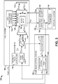
- FIG. 3 illustrates another example of a sensor system 100.
- the sensor system 100 can correspond to a portion of an NMR gyroscope, an NMR magnetometer, an EPR magnetometer, or a combination thereof.
- the sensor system 100 can be implemented in any of a variety of applications, such as detection, guidance, and/or aviation systems.
- the sensor system 100 can be implemented as a portion of an overall sensor application, such as can be configured to operate in multiple axes.
- the sensor system 100 includes a cell system 102 and a pump beam control system 104.
- the cell system 102 includes a sensor cell 106.
- the sensor cell 106 can be, for example, a glass casing of any of a variety of shapes and sizes.
- the sensor cell 106 includes an alkali metal 108, as well as one or more nuclear spin isotopes (not shown), in the example of the sensor system 100 being configured as an NMR system.
- the alkali metal 108 can be Rb vapor, such as 85 Rb, to substantially reduce a difference between the ground-state transition frequencies of the alkali metal 108 relative to other alkali metal types (e.g., Cs), as described previously in the example of FIG. 2 .
- the nuclear spin isotope(s) can include noble gas isotopes.
- the cell system 102 also includes a magnetic field generator 110 that is configured to generate a magnetic field B E .
- the magnetic field generator 110 can be configured as a magnetic solenoid that substantially surrounds the sensor cell 106 to generate the magnetic field B E as a substantially uniform magnetic field.
- the particles of the alkali metal 108 and the nuclear spin isotopes can precess relative to an axis of the sensor cell 106.
- the cell system 102 also includes a pump laser 112.
- the pump laser 112 can be configured to generate an optical pump beam O PMP_S having a linear polarization (e.g., the "s" polarization).
- the optical pump beam O PMP_S is directed through a beamsplitter 114 and a quarter-wave plate 116.
- the quarter-wave plate 116 is configured to change the linear polarization of the optical pump beam O PMP_S to a circular polarization, demonstrated as the optical pump beam O PMP_C .
- the optical pump beam O PMP_C is directed through the sensor cell 106 to stimulate ( i.e., excite) the particles of the alkali metal 108 to a polarized state.
- the optical pump beam O PMP_C is directed through the sensor cell 106 twice based on reflection of the optical pump beam O PMP_C from a mirror 118 at a distal side of the sensor cell 106, with the reflected optical pump beam being demonstrated as O PMP_C '.
- optical pumping of the particles of the alkali metal 108 can be substantially increased.
- the reflected optical pump beam O PMP_C ' exiting the sensor cell 106 is directed through the quarter-wave plate 116, thus transforming the circular polarization to a linear polarization.
- the linear polarization of the optical pump beam is oriented orthogonally with respect to the optical pump beam O PMP_S provided by the pump laser 112, and is thus demonstrated as optical pump beam O PMP_P to denote the "p" polarization. Therefore, upon being provided to the beamsplitter 114, the optical pump beam O PMP_P is reflected and directed to the pump beam control system 104. Accordingly, the pump beam control system 104 can monitor optical absorption of the optical pump beam O PMP_C based on the intensity of the optical pump beam O PMP_P . As described herein, optical absorption of the optical pump beam O PMP_C denotes a collective optical absorption of the optical pump beams O PMP_C and O PMP_C '.
- the particles of the alkali metal 108 can be subject to AC Stark shift, in which the optical pumping of the particles of the alkali metal 108 via the pump laser 112 is off-resonance with respect to one or both atomic transition wavelengths corresponding to two independent ground states of the alkali metal 108.
- the pump laser 112 can be oriented to generate the optical pump beam O PMP_C at an offset angle ⁇ with respect to the applied magnetic field B E .
- the pump laser 112 can be physically oriented at the offset angle ⁇ , such that the optical pump beam O PMP_C is provided through the sensor cell 106 at the offset angle ⁇ , or the cell system 102 can include additional optics to provide the optical pump beam O PMP_C through the sensor cell 106 at the offset angle ⁇ .
- the pump beam control system 104 includes a stabilization system 120 and a photodetector 122.
- the stabilization system 120 includes a PWM controller 124.
- the stabilization system 120 is configured to generate a modulation current I MOD that is provided to the pump laser 112. Therefore, the amplitude and frequency of the pump laser 112 can be set based on a magnitude of the modulation current I MOD .
- the stabilization system 120 can thus pulse-width modulate the magnitude of the modulation current I MOD based on the PWM controller 124.
- the frequency of the optical pump beam O PMP_S provided by the pump laser 112 is pulse-width modulated to have a duty-cycle, as provided by the PWM controller 124, such that the absorption of the optical pump beam O PMP_C varies inter alia as a function of the amplitudes of the respective portions of the duty-cycle, similar to as demonstrated in the example of FIG. 2 .
- the optical pump beam O PMP_C is pulse-width modulated.
- the optical pump beam O PMP_P is provided from the beamsplitter 114 to the photodetector 122, such that the photodetector 122 is configured to generate an absorption voltage V DET that corresponds to the intensity of the optical pump beam O PMP_P , which thus corresponds to the absorption of the optical pump beam O PMP_C in the sensor cell 106.
- the absorption voltage V DET is provided to the stabilization system 120, such that the stabilization system 120 can monitor the absorption of the optical pump beam O PMP_C based on the absorption voltage V DET . Because the frequency of the optical pump beam O PMP_C varies based on the duty-cycle, the absorption voltage V DET likewise varies at approximately the duty-cycle.
- the stabilization system 120 can be configured to determine the absorption spectrum of the optical pump beam O PMP_P as a time-average through the pulse-width modulation period. As a result, the stabilization system 120 can determine a frequency of the optical pump beam O PMP_S generated by the pump laser 112 that corresponds to substantial maximum absorption of the optical pump beam O PMP_C through the sensor cell 106 (e.g., the center of the frequency band between the transition frequencies).
- the sensor system 100 also includes a detection system 126 that is configured to calculate at least one measurable parameter.
- the measurable parameter can include rotation about a sensitive axis in the example of the sensor system 100 being configured as an NMR gyroscope, or can include a vector magnitude of an external magnetic field in the example of the sensor system 100 being configured as an NMR/EPR magnetometer.
- the detection system 126 includes a probe laser 128, a rotation detector 130, and a measurement controller 132.
- the probe laser 128 can be configured to generate a probe beam O PRB that passes through the sensor cell 106.
- the precession of the particles of the alkali metal 108 and the associated nuclear spin isotopes can result in phase changes associated with a detection beam O DET corresponding to the probe beam exiting the sensor cell 106.
- the detection beam O DET is provided to the rotation detector 130, which is configured to generate a signal FAR that is indicative of the Faraday rotation of the detection beam O DET . Therefore, the measurement controller 132 can calculate the measurable parameter based on changes in the precession of the particles of the alkali metal 108, such as resulting from rotation of the sensor cell 106 or an external magnetic field, which is indicated by the Faraday rotation of the detection beam O DET as provided by the signal FAR.
- the optical pump beam O PMP_C can be oriented at an offset angle ⁇ with respect to the applied magnetic field B E .
- the AC Stark shift induces an AC virtual magnetic field B L in a vector direction that is orthogonal to the applied magnetic field B E based on vector components of the optical pump beam O PMP_C in the plane orthogonal to the applied magnetic field B E .
- the induced AC magnetic field B L can thus likewise vary based on the duty-cycle of the optical pump beam O PMP_S . Therefore, the AC magnetic field B L can affect the precession of the alkali metal 108 at the duty-cycle.
- the detection beam O DET can have a Faraday rotation that varies at the duty-cycle resulting from the induced magnetic field B L .
- the rotation detector 130 can thus also provide the signal FAR to the stabilization system 120.
- the stabilization system 120 can be configured to demodulate the signal FAR based on the duty-cycle, such that the stabilization system 120 can determine an effect of the AC Stark shift on the detection beam O DET .
- the stabilization system 120 can thus obtain a DC error signal having a magnitude and a sign that corresponds to the effects of the AC Stark shift, and thus a deviation from a duty-cycle of the optical pump beam O PMP_S at which the effects of the AC Stark shift are equal and opposite.
- the stabilization system 120 can adjust the duty-cycle of the pump beam O PMP_S based on the DC error signal to substantially minimize the DC error signal (e.g., set to a zero value) in a feedback manner.
- the time-averaged frequency of the optical pump beam O PMP_S over the pulse-width modulation period is approximately equal to the frequency value at which the effects of the AC Stark shift are approximately equal and opposite with respect to excitation of the particles of the alkali metal 108 out of the two independent ground states.
- the stabilization system 120 can continuously demodulate the signal FAR at the duty-cycle to monitor the Faraday rotation of the detection beam O DET and can adjust the duty-cycle of the optical pump beam O PMP_S based on the modulation current I MOD in a feedback manner.
- the time-averaged frequency of the PWM pump beam O PMP_S and thus the optical pump beam O PMP_C , is maintained at a frequency at which the effects of the AC Stark shift are equal and opposite with respect to the two independent ground states of the alkali metal 108.
- the stabilization system 120 stabilizes the AC Stark shift while maintaining off-resonance pumping of the alkali metal vapor 108 to substantially maximize polarization uniformity of the alkali metal vapor 108 to improve performance of the sensor system 100 in measuring the measurable parameter. Furthermore, because the time-averaged AC Stark shift effects are substantially equal and opposite based on the PWM duty-cycle, the AC Stark shift effects are substantially mitigated. Accordingly, scale factor and bias errors associated with the measurable parameter(s) of the sensor system 100 is likewise substantially mitigated.
- absorption of the optical pump beam O PMP_C is based in part on temperature of the sensor cell 106.
- the cell system 102 also includes a cell temperature controller 134 that is configured to set the temperature of the sensor cell 106.
- the stabilization system 120 can be configured to stabilize the temperature of the sensor cell 106 via the cell temperature controller 134 based on the monitored absorption of the optical pump beam O PMP_C via the absorption voltage V DET .
- the stabilization system 120 can determine changes in the absorption of the optical pump beam O PMP_C based on the demodulated absorption voltage V DET and can provide a temperature control signal TEMP_CTRL to the cell temperature controller 134 to modify the temperature of the sensor cell 106 to substantially compensate for the changes in absorption of the optical pump beam O PMP_C . Therefore, the stabilization system 120 can likewise stabilize the temperature of the sensor cell 106 based on the absorption voltage V DET in a feedback manner to provide for substantially optimal absorption of the optical pump beam O PMP_C .
- FIG. 4 a methodology in accordance with various aspects of the present invention will be better appreciated with reference to FIG. 4 . While, for purposes of simplicity of explanation, the methodology of FIG. 4 is shown and described as executing serially, it is to be understood and appreciated that the present invention is not limited by the illustrated order, as some aspects could, in accordance with the present invention, occur in different orders and/or concurrently with other aspects from that shown and described herein. Moreover, not all illustrated features may be required to implement a methodology in accordance with an aspect of the present invention.
- FIG. 4 illustrates an example of a method 150 for substantially mitigating AC Stark shift effects in a sensor system (e.g., the sensor system 10).
- a circularly-polarized pump beam e.g., the optical pump beam O PMP_S
- a frequency of the pump beam is pulse-width modulated about a center frequency (e.g., the wavelength ⁇ C ) to provide a PWM pump beam having a duty-cycle (e.g., the "ON" time 58 and the "OFF" time 60).
- the PWM pump beam is provided through a sensor cell (e.g., the sensor cell 14) to polarize an alkali metal vapor (e.g., the alkali metal vapor 18) enclosed within the sensor cell to facilitate precession of the alkali metal vapor via a magnetic field (e.g., the magnetic field B E ).
- a linearly-polarized probe beam e.g., the probe beam O PRB ) is provided through the sensor cell.
- a Faraday rotation of a detection beam (e.g., the detection beam O DET ) corresponding to the linearly-polarized probe beam exiting the sensor cell is demodulated based on the duty-cycle to determine a time-averaged frequency of the PWM pump beam over a pulse-width modulation period of the PWM pump beam.
- the duty-cycle of the PWM pump beam is controlled based on the demodulated Faraday rotation to adjust the time-averaged frequency to substantially stabilize and mitigate the effects of AC Stark shift on the at least one measurable parameter.
Description
- The present invention relates generally to sensor systems, and specifically to optical pump beam control in a sensor system.
- Sensor systems, such as nuclear magnetic resonance (NMR) gyroscopes and magnetometers and/or electron paramagnetic resonance (EPR) magnetometers, can include a cell that contains one or more alkali metal vapors, such as rubidium or cesium, together with one or more nuclear spin isotopes that are caused to precess in response to a magnetic field. The alkali metal vapor(s) can be stimulated to an excited state in response to optical pumping in a given frequency band. Optical pumping can be off-resonance with respect to an atomic transition wavelength of the alkali metal vapor(s), such as to provide polarization uniformity within the sensor cell. However, off-resonance pumping can also subject the alkali metal vapor to AC Stark shift, in which the atoms of the alkali metal vapor experience a virtual magnetic field that is not experienced by the nuclear spin isotopes. The resultant effect of the AC Stark shift is an added bias in the detected magnetic field of the associated magnetometer or an added bias in the rotation angle and/or rate of the associated gyroscope, and thus errors in their respective measurable parameters. Because alkali metals have two independent ground states, and thus two separate atomic transition frequencies, AC Stark shift is unavoidable in the optical pumping of the alkali metals.
- Document
EP-A-2 749 895 discloses a sensor system with means for mitigating AC Stark shift. In particular, a frequency of a pump beam is modulated and the center frequency of the frequency-modulated pump beam is controlled based on the characteristics of a probe beam passing through the sensor cell to mitigate the effects of AC Stark shift on a measurable parameter. - One aspect of the invention concerns a sensor system comprising: a cell system comprising a pump laser configured to generate a circularly polarized pump beam to polarize alkali metal vapor enclosed within a sensor cell of the sensor system, and a magnetic field generator configured to generate a magnetic field within the sensor cell; a detection system comprising a probe laser configured to generate a probe beam, the detectuion system being configured to calculate at least one measurable parameter based on characteristics of the probe beam passing through the sensor cell resulting from precession of the polarized alkali metal vapor in response to an applied magnetic field; and a pump beam control system configured to pulse-width modulate a frequency of the pump beam to provide a pulse-width modulated (PWM) pump beam, and to control a duty-cycle of the PWM pump beam based on the characteristics of the probe beam passing through the sensor cell in a feedback manner to control polarization uniformity of the alkali metal vapor and to mitigate the effects of AC Stark shift on the at least one measurable parameter, wherein the pump beam control system is configured to control the duty-cycle in the feedback manner to maintain the duty-cycle at which the effects of the AC Stark shift are substantially equal and opposite with respect to a pulse-width modulation period of the PWM pump beam based on the characteristics of the probe beam passing through the sensor cell.
- Another aspect of the invention concerns a method for substantially mitigating AC Stark shift effects in a sensor system configured to calculate at least one measurable parameter. The method includes generating a circularly-polarized pump beam and pulse-width modulating a frequency of the pump beam about a center frequency to provide a PWM pump beam having a duty-cycle. The method also includes providing the PWM pump beam through a sensor cell to polarize an alkali metal vapor enclosed within the sensor cell to facilitate precession of the alkali metal vapor via a magnetic field and providing a linearly-polarized probe beam through the sensor cell. The method also includes demodulating a Faraday rotation of a detection beam corresponding to the linearly-polarized probe beam exiting the sensor cell based on the duty-cycle to determine a time-averaged frequency of the PWM pump beam over a pulse-width modulation period of the PWM pump beam. The method further includes controlling the duty-cycle of the PWM pump beam based on the demodulated Faraday rotation to adjust the time-averaged frequency to substantially stabilize and mitigate the effects of AC Stark shift on the at least one measurable parameter, and controlling the duty-cycle to maintain the duty-cycle at which the effects of the AC Stark shift are substantially equal and opposite with respect to a pulse-width modulation period of the PWM pump beam based on the characteristics of the probe beam passing through the sensor cell.
-
-
FIG. 1 illustrates an example of a sensor system. -
FIG. 2 illustrates an example timing diagram of a pulse-width modulation signal waveform. -
FIG. 3 illustrates another example of a sensor system. -
FIG. 4 illustrates an example of a method for controlling an optical pump beam in a sensor system. - The present invention relates generally to sensor systems, and specifically to optical pump beam control in a sensor system. A sensor system, such as a nuclear magnetic resonance (NMR) gyroscope, an NMR magnetometer, or an electron paramagnetic resonance (EPR) magnetometer, can include a cell system that includes a pump laser configured to generate a pump beam to polarize alkali metal particles enclosed within a sensor cell. A detection system can be configured to calculate at least one measurable parameter, such as rotation about a sensitive axis or an external magnetic field, based on precession of the polarized alkali metal particles in response to an applied magnetic field. As an example, the precession of the polarized alkali metal particles can be coupled with precession of nuclear spin isotopes such as xenon (e.g., 129Xe or 131Xe), such that the Larmor precession frequency and/or phase information of the one or more nuclear spin isotopes can be extracted to calculate the measurable parameter. The sensor system can also include a pump beam control system configured to monitor optical absorption of the pump beam passing through the sensor cell and to pulse-width modulate a frequency of the pump beam to substantially mitigate the effects of AC Stark shift on the at least one measurable parameter based on the pulse-width modulated (PWM) pump beam.
- The monitoring of the optical absorption can be based on linearly polarized light associated with the pump beam exiting the sensor cell being incident on a photodetector, such as can be associated with circularly polarized optical pump light passing through an appropriately oriented quarter-wave plate. A center frequency of the PWM pump beam can be set to approximately a frequency value of substantial maximum absorption of the pump beam passing through the sensor cell, such that the pulse-width modulation of the pump beam can be between first and second frequencies that are substantially equal and opposite the center frequency through a given pulse-width modulation period of the duty-cycle. The PWM pump beam can induce a virtual magnetic field within the sensor cell that affects the precession of the alkali metal particles in a manner that is associated with the AC Stark shift effects at the first and second frequencies associated with the duty-cycle. Therefore, a probe beam that is provided through the sensor cell that can exhibit characteristics associated with the at least one measurable parameter can exhibit a Faraday rotation at each of the first and second frequencies. Therefore, the Faraday rotation can be demodulated based on the duty-cycle to generate a DC error signal corresponding to the effects of the AC Stark shift. Accordingly, the duty-cycle of the PWM pump beam can be adjusted (e.g., digitally) based on the DC error signal to maintain the duty-cycle such that the effects of the AC Stark shift are equal and opposite with respect to the time duration of the first and second frequencies of the PWM pump beam in a feedback manner. As a result, the AC Stark shift is substantially stabilized, such that the time-averaged effects of the AC Stark shift are substantially mitigated with respect to the at least one measurable parameter.
-
FIG. 1 illustrates an example of asensor system 10. As an example, thesensor system 10 can correspond to one or more of a nuclear magnetic resonance (NMR) gyroscope, an NMR magnetometer, an electron paramagnetic resonance (EPR) magnetometer, or a combination thereof. Thesensor system 10 can be implemented in any of a variety of applications, such as detection, guidance, and/or aviation systems. As another example, thesensor system 10 can be implemented as a portion of an overall sensor application, such as can be configured to operate in multiple axes. - The
sensor system 10 includes acell system 12 that includes asensor cell 14 and apump laser 16. Thesensor cell 14 can be, for example, a glass casing of any of a variety of shapes and sizes. Thesensor cell 14 includes analkali metal 18, as well as one or more nuclear spin isotopes (not shown) in the case of an NMR sensor. As an example, thealkali metal 18 can be rubidium (Rb) vapor, such as 85Rb, or cesium (Cs) vapor, such as 133Cs, and the nuclear spin isotope(s) can include noble gas isotopes such as helium (He), krypton (Kr), and/or xenon (Xe) (e.g., 3He, 83Kr, 129Xe, and/or 131Xe). Thepump laser 16 can be configured to generate an optical pump beam that is circularly-polarized and directed through thesensor cell 14 via a set of optics to stimulate (i.e., excite) the particles of thealkali metal 18 to a spin-polarized state. The spin-polarized particles of thealkali metal 18 can precess in thesensor cell 14 in response to an applied magnetic field (e.g., an AC and/or DC magnetic field applied along a sensitive axis), such as may be generated by the precessing nuclear spin isotopes. For example, the polarized particles of thealkali metal 18 can experience EPR precession due to a DC or AC magnetic field along an EPR sensitive axis (e.g., the X- and/or Y-axis) that is stimulated by the applied magnetic field (e.g., a DC and AC magnetic field resonant with the EPR Larmor precession frequency along the EPR insensitive Z-axis), and the nuclear spin isotopes can precess about the applied magnetic field (e.g., a DC magnetic field along the EPR insensitive Z-axis) in response to a magnetic field resonant with the NMR Larmor precession frequency or frequencies applied in the X-Y plane. Furthermore, thesensor cell 14 can also include one or more buffer gases. - The
sensor system 10 also includes adetection system 20 that is configured to calculate at least one measurable parameter. For example, the measurable parameter can include rotation about a sensitive axis in the example of thesensor system 10 being configured as an NMR gyroscope, or can include a vector magnitude of an external magnetic field in the example of thesensor system 10 being configured as an NMR and/or EPR magnetometer. In the example ofFIG. 1 , thedetection system 20 includes aprobe laser 22 and arotation detector 24. Theprobe laser 22 can be configured to generate a probe beam that passes through thesensor cell 14. The precession of the particles of thealkali metal 18 and the associated nuclear spin isotopes can result in polarization phase changes associated with the probe beam exiting the sensor cell 14 (e.g., based on interaction between the photons from theprobe laser 22 and the particles of the alkali metal 18). Therefore, thedetection system 20 can calculate the measurable parameter based on changes in the precession of the particles of thealkali metal 18, such as resulting from rotation of thesensor cell 14 or an external magnetic field, such as based on therotation detector 24 determining a Faraday rotation of the probe beam. - The particles of the
alkali metal 18 can be subject to AC Stark shift, in which the optical pumping of the particles of thealkali metal 18 via thepump laser 16 is off-resonance with respect to atomic transition wavelengths corresponding to two independent ground states of thealkali metal 18. The AC Stark shift can cause a virtual magnetic field that is experienced by thealkali metal 18 but not by the nuclear spin isotopes, which causes a change to the precession of the particles of thealkali metal 18 relative to the nuclear spin isotopes. As a result, the AC Stark shift exhibits an added bias to the measurable parameter that is calculated by thedetection system 20. The virtual magnetic field is added to the applied magnetic field, such that if the AC Stark shift is stable, and if thesensor system 10 is tuned to an optimum operating point, thesensor system 10 experiences substantially no scale factor or bias errors arising from AC Stark shift effects. However, changes in intensity, frequency, and/or alignment of the optical pump beam, as well as vapor density of the alkali metal 18 (e.g., based on temperature of the sensor cell 14), can result in changes in the virtual magnetic field caused by the AC Stark shift, and thus changes in an overall magnitude of the applied magnetic field experienced by thealkali metal 18. - In the example of the
sensor system 10 being configured as a magnetometer, the sensitive axes of the magnetometer are defined based on an interaction of the particles of thealkali metal 18 relative to the applied magnetic field, as determined by thedetection system 20. For example, thedetection system 20 can demodulate a detection signal at a typically fixed phase relationship with the applied magnetic field, such that changes in the phase of the precession of the particles of thealkali metal 18 result in changes to the detection signal based on interaction of the probe beam and the precessing particles of thealkali metal 18 in thesensor cell 14. However, the effect of an unstable AC Stark shift with respect to changing the precession of the particles of thealkali metal 18 can result in a change in the magnetometer signal phase that can be perceived as components of an external magnetic field in vector angles rotated about the sensitive axis. - In the example of the
sensor system 10 being configured as a gyroscope, magnetic field feedback can be implemented to substantially null any detected magnetic fields in a cross-axis relative to the sensitive axis to maintain alignment of the sensitive axis to the applied magnetic field. Thus, a virtual magnetic field in a cross-axis direction caused by unstable AC Stark shift can be indistinguishable from a real magnetic field, such that the feedback system can generate a real magnetic field to offset the perceived virtual magnetic field. As described previously, the nuclear spin isotopes in thesensor cell 14 are not subject to effects of the virtual magnetic field, but are subject to the effects of a real magnetic field generated to offset the virtual magnetic field. As a result, the offset real magnetic field can cause misalignment, and thus instability, of the sensitive axis of the gyroscope. Furthermore, the presence of AC Stark Shift effects can alter the phase of the precession of the particles of thealkali metal 18 with respect to the precession of the nuclear spin isotopes. This phase offset can result in a phase offset in the feedback for stimulation of the precession of the nuclear spin isotopes, which can result in an angular rate bias. - To substantially stabilize and mitigate the effects of AC Stark shift, the
sensor system 10 includes a pumpbeam control system 26. The pumpbeam control system 26 includes astabilization system 28 that includes a pulse-width modulation (PWM)controller 30. Thestabilization system 28 is configured to pulse-width modulate the frequency of the optical pump beam provided by thepump laser 16 via thePWM controller 30 to provide a PWM pump beam, such that the absorption of the PWM pump beam passing through thesensor cell 14 varies inter alia as a function of the instantaneous frequency of the pump beam during a duty-cycle of the PWM pump beam. Thepump beam controller 26 is also configured to monitor the absorption of the PWM pump beam passing through thesensor cell 14, such as based on a set of optics and a photodetector, to control a temperature of thepump laser 16 to substantially maintain a center frequency of the PWM pump beam at an approximate maximum absorption of the PWM pump beam via thealkali metal vapor 18, thus corresponding to the transition frequencies associated with the independent ground states of thealkali metal 18. - As an example, the
stabilization system 28 can initially set a center frequency of the PWM pump beam to be approximately equal to the frequency of substantial maximum absorption. The PWM pump beam can induce a virtual magnetic field internal to thesensor cell 14 that affects the precession of the particles of thealkali metal 18 in a manner that is associated with the AC Stark shift effects, modulated at the duty-cycle of the PWM pump beam. For example, thepump laser 16 can be oriented in a manner to provide components of the induced magnetic field in a plane that is orthogonal to an axis about which the particles of thealkali metal 18 precess, such as based on an offset angle of the PWM pump beam relative to an applied magnetic field based on which thealkali metal vapor 18 precesses. Therefore, the probe beam that is generated by theprobe laser 22 can exhibit a Faraday rotation modulated at the duty-cycle in response to the induced virtual magnetic field in addition to a Faraday rotation based on the measurable parameter (e.g., which can occur at a much lower frequency). Therefore, thestabilization system 28 can demodulate the Faraday rotation of the probe beam based on the duty-cycle to generate a DC error signal that can correspond to the effects of the AC Stark shift. Accordingly, the duty-cycle of the PWM pump beam can be shifted based on the DC error signal in a feedback manner to maintain the DC error signal at a zero amplitude corresponding to a value at which the effects of the AC Stark shift are equal and opposite with respect to the duty-cycle, and thus with respect to the two independent ground states of thealkali metal 18, in a feedback manner. Accordingly, based on the feedback adjustment of the duty-cycle of the PWM pump beam by thestabilization system 28, thestabilization system 28 stabilizes the AC Stark shift while optically pumping thealkali metal vapor 18 off-resonance to substantially maximize polarization uniformity in thesensor cell 14. Furthermore, because the AC Stark shift effects are substantially equal and opposite with respect to the product of AC Stark shift magnitude, direction (e.g., positive or negative direction), and duty-cycle in each of the two off-resonance states about the center frequency based on excitation of thealkali metal 18 from the respective two independent ground states of thealkali metal 18, the AC Stark shift effects are substantially mitigated. Accordingly, scale factor and bias errors associated with the measurable parameter(s) of thesensor system 10 is likewise substantially mitigated. -
FIG. 2 illustrates an example timing diagram 50 of a pulse-width modulation signal waveform. As an example, the diagram 50 demonstrates the modulation signal DTH plotted as a function of time. The modulation signal DTH is demonstrated in the example ofFIG. 2 as a square-wave signal oscillating about a center wavelength λC. The modulation signal DTH is demonstrated as having a maximum amplitude corresponding to a first wavelength λMAX and a minimum amplitude corresponding to a second wavelength λMIN. In the example ofFIG. 2 , the first and second wavelengths λMAX and λMIN are separated equally and oppositely about the center wavelength λC by a wavelength difference λ1. - The pulse-width modulation signal waveform demonstrated in the timing diagram 50 can correspond to the PWM pump beam generated by the
pump laser 16. Thus, the center wavelength λC can be a wavelength that corresponds to an approximate maximum absorption of photons of the PWM pump beam by thealkali metal vapor 18, such that each of the wavelengths λMAX and λMIN are off-resonance with respect to a transition wavelength associated with thealkali metal vapor 18. The timing diagram 50 includes a first pulse-width modulation period 52, a second pulse-width modulation period 54, and a third pulse-width modulation period 56 of the PWM pump beam. Each of the pulse-width modulation periods time 58 at which the wavelength of the PWM pump beam is at the first wavelength λMAX and an "OFF"time 60 at which the wavelength of the PWM pump beam is at the second wavelength λMIN. The pulse-width modulation periods - As an example, based on demodulating a detection beam corresponding to the optical probe beam generated by the
probe laser 22 exiting thesensor cell 14, thestabilization system 28 can determine that the DC error signal has a non-zero value. Therefore, thealkali metal vapor 18 is exhibiting deleterious effects of AC Stark shift. In response to the DC error signal having a non-zero value, thestabilization system 28 is configured to adjust the duty-cycle of the PWM pump beam, such as based on digitally adjusting the clock cycles corresponding to "ON"time 58 relative to the "OFF"time 60. In the example ofFIG. 2 , thestabilization system 28 adjusts the duty-cycle of the pulse-width modulation period 54 relative to the pulse-width modulation period 52 by decreasing the "ON"time 58, and thus increasing the "OFF"time 60 in the pulse-width modulation period 54, such as by adjusting the clock cycles for each of the "ON"time 58 and the "OFF"time 60, based on the DC error signal. As an example, the DC error signal can have a polarity that is indicative of the AC Stark shift based on a time-average of the Faraday rotation of the detection beam over a given pulse-width modulation period. - Subsequently, based on demodulating the detection beam based on the duty-cycle and determining a time-averaged Faraday rotation of the detection beam, the
stabilization system 28 can again determine that the DC error signal has a non-zero value. Therefore, the adjustment to the duty-cycle of the pulse-width modulation period 54 was insufficient to negate the deleterious effects of AC Stark shift. In response to the DC error signal having the non-zero value, thestabilization system 28 again adjusts the duty-cycle of the PWM pump beam. In the example ofFIG. 2 , thestabilization system 28 adjusts the duty-cycle of the pulse-width modulation period 56 relative to the pulse-width modulation period 54 by again decreasing the "ON"time 58, and thus increasing the "OFF"time 60 in the pulse-width modulation period 56, such as by adjusting the clock cycles for each of the "ON"time 58 and the "OFF"time 60, based on the DC error signal. Accordingly, thestabilization system 28 can substantially continuously monitor the detection beam and adjust the duty-cycle of the PWM pump beam in a feedback manner to maintain a zero value of the DC error signal, and thus stabilize the effects of AC Stark shift. -
FIG. 3 illustrates another example of asensor system 100. As an example, thesensor system 100 can correspond to a portion of an NMR gyroscope, an NMR magnetometer, an EPR magnetometer, or a combination thereof. Thesensor system 100 can be implemented in any of a variety of applications, such as detection, guidance, and/or aviation systems. As another example, thesensor system 100 can be implemented as a portion of an overall sensor application, such as can be configured to operate in multiple axes. - The
sensor system 100 includes acell system 102 and a pumpbeam control system 104. In the example ofFIG. 3 , thecell system 102 includes asensor cell 106. Thesensor cell 106 can be, for example, a glass casing of any of a variety of shapes and sizes. Thesensor cell 106 includes analkali metal 108, as well as one or more nuclear spin isotopes (not shown), in the example of thesensor system 100 being configured as an NMR system. As an example, thealkali metal 108 can be Rb vapor, such as 85Rb, to substantially reduce a difference between the ground-state transition frequencies of thealkali metal 108 relative to other alkali metal types (e.g., Cs), as described previously in the example ofFIG. 2 . In addition, as an example, the nuclear spin isotope(s) can include noble gas isotopes. Thecell system 102 also includes amagnetic field generator 110 that is configured to generate a magnetic field BE. As an example, themagnetic field generator 110 can be configured as a magnetic solenoid that substantially surrounds thesensor cell 106 to generate the magnetic field BE as a substantially uniform magnetic field. In response to the magnetic field BE, the particles of thealkali metal 108 and the nuclear spin isotopes can precess relative to an axis of thesensor cell 106. - The
cell system 102 also includes apump laser 112. Thepump laser 112 can be configured to generate an optical pump beam OPMP_S having a linear polarization (e.g., the "s" polarization). The optical pump beam OPMP_S is directed through abeamsplitter 114 and a quarter-wave plate 116. The quarter-wave plate 116 is configured to change the linear polarization of the optical pump beam OPMP_S to a circular polarization, demonstrated as the optical pump beam OPMP_C. The optical pump beam OPMP_C is directed through thesensor cell 106 to stimulate (i.e., excite) the particles of thealkali metal 108 to a polarized state. In the example ofFIG. 3 , the optical pump beam OPMP_C is directed through thesensor cell 106 twice based on reflection of the optical pump beam OPMP_C from amirror 118 at a distal side of thesensor cell 106, with the reflected optical pump beam being demonstrated as OPMP_C'. Thus, optical pumping of the particles of thealkali metal 108 can be substantially increased. - The reflected optical pump beam OPMP_C' exiting the
sensor cell 106 is directed through the quarter-wave plate 116, thus transforming the circular polarization to a linear polarization. However, the linear polarization of the optical pump beam is oriented orthogonally with respect to the optical pump beam OPMP_S provided by thepump laser 112, and is thus demonstrated as optical pump beam OPMP_P to denote the "p" polarization. Therefore, upon being provided to thebeamsplitter 114, the optical pump beam OPMP_P is reflected and directed to the pumpbeam control system 104. Accordingly, the pumpbeam control system 104 can monitor optical absorption of the optical pump beam OPMP_C based on the intensity of the optical pump beam OPMP_P. As described herein, optical absorption of the optical pump beam OPMP_C denotes a collective optical absorption of the optical pump beams OPMP_C and OPMP_C'. - As described herein, the particles of the
alkali metal 108 can be subject to AC Stark shift, in which the optical pumping of the particles of thealkali metal 108 via thepump laser 112 is off-resonance with respect to one or both atomic transition wavelengths corresponding to two independent ground states of thealkali metal 108. To ensure that the AC Stark shift is measurable, thepump laser 112 can be oriented to generate the optical pump beam OPMP_C at an offset angle θ with respect to the applied magnetic field BE. For example, thepump laser 112 can be physically oriented at the offset angle θ, such that the optical pump beam OPMP_C is provided through thesensor cell 106 at the offset angle θ, or thecell system 102 can include additional optics to provide the optical pump beam OPMP_C through thesensor cell 106 at the offset angle θ. - The pump
beam control system 104 includes astabilization system 120 and aphotodetector 122. Thestabilization system 120 includes aPWM controller 124. Thestabilization system 120 is configured to generate a modulation current IMOD that is provided to thepump laser 112. Therefore, the amplitude and frequency of thepump laser 112 can be set based on a magnitude of the modulation current IMOD. Thestabilization system 120 can thus pulse-width modulate the magnitude of the modulation current IMOD based on thePWM controller 124. As a result, the frequency of the optical pump beam OPMP_S provided by thepump laser 112 is pulse-width modulated to have a duty-cycle, as provided by thePWM controller 124, such that the absorption of the optical pump beam OPMP_C varies inter alia as a function of the amplitudes of the respective portions of the duty-cycle, similar to as demonstrated in the example ofFIG. 2 . Thus, the optical pump beam OPMP_C is pulse-width modulated. - The optical pump beam OPMP_P is provided from the
beamsplitter 114 to thephotodetector 122, such that thephotodetector 122 is configured to generate an absorption voltage VDET that corresponds to the intensity of the optical pump beam OPMP_P, which thus corresponds to the absorption of the optical pump beam OPMP_C in thesensor cell 106. The absorption voltage VDET is provided to thestabilization system 120, such that thestabilization system 120 can monitor the absorption of the optical pump beam OPMP_C based on the absorption voltage VDET. Because the frequency of the optical pump beam OPMP_C varies based on the duty-cycle, the absorption voltage VDET likewise varies at approximately the duty-cycle. Therefore, thestabilization system 120 can be configured to determine the absorption spectrum of the optical pump beam OPMP_P as a time-average through the pulse-width modulation period. As a result, thestabilization system 120 can determine a frequency of the optical pump beam OPMP_S generated by thepump laser 112 that corresponds to substantial maximum absorption of the optical pump beam OPMP_C through the sensor cell 106 (e.g., the center of the frequency band between the transition frequencies). - In the example of
FIG. 3 , thesensor system 100 also includes adetection system 126 that is configured to calculate at least one measurable parameter. For example, the measurable parameter can include rotation about a sensitive axis in the example of thesensor system 100 being configured as an NMR gyroscope, or can include a vector magnitude of an external magnetic field in the example of thesensor system 100 being configured as an NMR/EPR magnetometer. In the example ofFIG. 3 , thedetection system 126 includes aprobe laser 128, arotation detector 130, and ameasurement controller 132. Theprobe laser 128 can be configured to generate a probe beam OPRB that passes through thesensor cell 106. The precession of the particles of thealkali metal 108 and the associated nuclear spin isotopes can result in phase changes associated with a detection beam ODET corresponding to the probe beam exiting thesensor cell 106. The detection beam ODET is provided to therotation detector 130, which is configured to generate a signal FAR that is indicative of the Faraday rotation of the detection beam ODET. Therefore, themeasurement controller 132 can calculate the measurable parameter based on changes in the precession of the particles of thealkali metal 108, such as resulting from rotation of thesensor cell 106 or an external magnetic field, which is indicated by the Faraday rotation of the detection beam ODET as provided by the signal FAR. - In addition, as described previously, the optical pump beam OPMP_C can be oriented at an offset angle θ with respect to the applied magnetic field BE. As a result, the AC Stark shift induces an AC virtual magnetic field BL in a vector direction that is orthogonal to the applied magnetic field BE based on vector components of the optical pump beam OPMP_C in the plane orthogonal to the applied magnetic field BE. The induced AC magnetic field BL can thus likewise vary based on the duty-cycle of the optical pump beam OPMP_S. Therefore, the AC magnetic field BL can affect the precession of the
alkali metal 108 at the duty-cycle. As a result, in addition to the Faraday rotation of the detection beam ODET resulting from the rotation of thesensor cell 106 or an external magnetic field, the detection beam ODET can have a Faraday rotation that varies at the duty-cycle resulting from the induced magnetic field BL. - The
rotation detector 130 can thus also provide the signal FAR to thestabilization system 120. Thus, thestabilization system 120 can be configured to demodulate the signal FAR based on the duty-cycle, such that thestabilization system 120 can determine an effect of the AC Stark shift on the detection beam ODET. Thestabilization system 120 can thus obtain a DC error signal having a magnitude and a sign that corresponds to the effects of the AC Stark shift, and thus a deviation from a duty-cycle of the optical pump beam OPMP_S at which the effects of the AC Stark shift are equal and opposite. As a result, thestabilization system 120 can adjust the duty-cycle of the pump beam OPMP_S based on the DC error signal to substantially minimize the DC error signal (e.g., set to a zero value) in a feedback manner. Thus, upon the DC error signal being approximately equal to zero, the time-averaged frequency of the optical pump beam OPMP_S over the pulse-width modulation period is approximately equal to the frequency value at which the effects of the AC Stark shift are approximately equal and opposite with respect to excitation of the particles of thealkali metal 108 out of the two independent ground states. - Therefore, the
stabilization system 120 can continuously demodulate the signal FAR at the duty-cycle to monitor the Faraday rotation of the detection beam ODET and can adjust the duty-cycle of the optical pump beam OPMP_S based on the modulation current IMOD in a feedback manner. As a result, the time-averaged frequency of the PWM pump beam OPMP_S, and thus the optical pump beam OPMP_C, is maintained at a frequency at which the effects of the AC Stark shift are equal and opposite with respect to the two independent ground states of thealkali metal 108. Accordingly, based on the feedback pulse-width modulation of the optical pump beam OPMP_S by thestabilization system 120, thestabilization system 120 stabilizes the AC Stark shift while maintaining off-resonance pumping of thealkali metal vapor 108 to substantially maximize polarization uniformity of thealkali metal vapor 108 to improve performance of thesensor system 100 in measuring the measurable parameter. Furthermore, because the time-averaged AC Stark shift effects are substantially equal and opposite based on the PWM duty-cycle, the AC Stark shift effects are substantially mitigated. Accordingly, scale factor and bias errors associated with the measurable parameter(s) of thesensor system 100 is likewise substantially mitigated. - In addition, as described previously, absorption of the optical pump beam OPMP_C is based in part on temperature of the
sensor cell 106. In the example ofFIG. 3 , thecell system 102 also includes acell temperature controller 134 that is configured to set the temperature of thesensor cell 106. Thestabilization system 120 can be configured to stabilize the temperature of thesensor cell 106 via thecell temperature controller 134 based on the monitored absorption of the optical pump beam OPMP_C via the absorption voltage VDET. As an example, thestabilization system 120 can determine changes in the absorption of the optical pump beam OPMP_C based on the demodulated absorption voltage VDET and can provide a temperature control signal TEMP_CTRL to thecell temperature controller 134 to modify the temperature of thesensor cell 106 to substantially compensate for the changes in absorption of the optical pump beam OPMP_C. Therefore, thestabilization system 120 can likewise stabilize the temperature of thesensor cell 106 based on the absorption voltage VDET in a feedback manner to provide for substantially optimal absorption of the optical pump beam OPMP_C. - In view of the foregoing structural and functional features described above, a methodology in accordance with various aspects of the present invention will be better appreciated with reference to
FIG. 4 . While, for purposes of simplicity of explanation, the methodology ofFIG. 4 is shown and described as executing serially, it is to be understood and appreciated that the present invention is not limited by the illustrated order, as some aspects could, in accordance with the present invention, occur in different orders and/or concurrently with other aspects from that shown and described herein. Moreover, not all illustrated features may be required to implement a methodology in accordance with an aspect of the present invention. -
FIG. 4 illustrates an example of amethod 150 for substantially mitigating AC Stark shift effects in a sensor system (e.g., the sensor system 10). At 152, a circularly-polarized pump beam (e.g., the optical pump beam OPMP_S) is generated. At 154, a frequency of the pump beam is pulse-width modulated about a center frequency (e.g., the wavelength λC) to provide a PWM pump beam having a duty-cycle (e.g., the "ON"time 58 and the "OFF" time 60). At 156, the PWM pump beam is provided through a sensor cell (e.g., the sensor cell 14) to polarize an alkali metal vapor (e.g., the alkali metal vapor 18) enclosed within the sensor cell to facilitate precession of the alkali metal vapor via a magnetic field (e.g., the magnetic field BE). At 158, a linearly-polarized probe beam (e.g., the probe beam OPRB) is provided through the sensor cell. At 160, a Faraday rotation of a detection beam (e.g., the detection beam ODET) corresponding to the linearly-polarized probe beam exiting the sensor cell is demodulated based on the duty-cycle to determine a time-averaged frequency of the PWM pump beam over a pulse-width modulation period of the PWM pump beam. At 162, the duty-cycle of the PWM pump beam is controlled based on the demodulated Faraday rotation to adjust the time-averaged frequency to substantially stabilize and mitigate the effects of AC Stark shift on the at least one measurable parameter. - What have been described above are examples of the present invention. It is, of course, not possible to describe every conceivable combination of components or methodologies for purposes of describing the present invention, but one of ordinary skill in the art will recognize that many further combinations and permutations of the present invention are possible. Accordingly, the present invention is intended to embrace all such alterations, modifications and variations that fall within the scope of the appended claims.
Claims (14)
- A sensor system comprising:a cell system comprising a pump laser (112) configured to generate a circularly polarized pump beam to polarize alkali metal vapor enclosed within a sensor cell (106) of the sensor system, and a magnetic field generator (110) configured to generate a magnetic field within the sensor cell;a detection system (20) comprising a probe laser (128) configured to generate a probe beam, the detection system being configured to calculate at least one measurable parameter based on characteristics of the probe beam passing through the sensor cell resulting from precession of the polarized alkali metal vapor in response to an applied magnetic field; anda pump beam control system (104) configured to pulse-width modulate a frequency of the pump beam to provide a pulse-width modulated (PWM) pump beam, and to control a duty-cycle of the PWM pump beam based on the characteristics of the probe beam passing through the sensor cell in a feedback manner to control polarization uniformity of the alkali metal vapor and to mitigate the effects of AC Stark shift on the at least one measurable parameter,wherein the pump beam control system is configured to control the duty-cycle in the feedback manner to maintain the duty-cycle at which the effects of the AC Stark shift are substantially equal and opposite with respect to a pulse-width modulation period of the PWM pump beam based on the characteristics of the probe beam passing through the sensor cell.
- The system of claim 1, wherein the pump beam control system comprises a stabilization system (120) configured to generate a current that is provided to the pump laser to set the frequency of the pump beam to each of a first frequency and a second frequency corresponding to the duty-cycle of the PWM pump beam, the stabilization system comprising a PWM controller (124) configured to control an amplitude of the current to set the duty-cycle of the PWM pump beam based on a Faraday rotation of the probe beam.
- The system of claim 2, wherein the pump laser (112) is oriented to provide the PWM pump beam at an offset angle with respect to the applied magnetic field to generate an induced virtual magnetic field internal to the sensor cell that is substantially coplanar with the probe beam corresponding to the effects of the AC Stark shift, the induced virtual magnetic field providing the Faraday rotation of the probe beam to be approximately equal to the duty-cycle of the PWM pump beam.
- The system of claim 2, wherein the stabilization system is configured to control the duty-cycle of the PWM pump beam based on demodulating the Faraday rotation of the probe beam by the duty-cycle to substantially maintain the duty-cycle of the PWM pump beam at a duty-cycle at which the effects of the AC Stark shift are substantially at a time-averaged zero magnitude.
- The system of any preceding claim, wherein the pump beam control system is configured to monitor an optical absorption of the PWM pump beam and to pulse-width modulate the frequency of the pump beam about a center frequency corresponding to an approximate maximum absorption of the PWM pump beam via the alkali metal vapor.
- The system of claim 5, wherein the cell system further comprises a cell temperature controller (134) configured to set a temperature of the sensor cell via a feedback temperature control signal to substantially stabilize a time-averaged optical absorption of the PWM pump beam passing through the sensor cell based on the monitored optical absorption of the PWM pump beam.
- The system of claim 5 or 6, wherein the pump beam control system comprises a stabilization system configured to digitally adjust the duty-cycle of the PWM pump beam based on setting a number of clock pulses of the PWM pump beam in a first frequency and a number of clock pulses of the PWM pump beam in a second frequency relative to a fixed number of clock pulses of a pulse-width modulation period, wherein the first and second frequencies are substantially equal and opposite with respect to the center frequency.
- The system of any preceding claim, wherein the sensor system is configured as at least one of a nuclear magnetic resonance (NMR) gyroscope, an NMR magnetometer, and an electron paramagnetic resonance (EPR) magnetometer.
- A method for substantially mitigating AC Stark shift effects in a sensor system configured to calculate at least one measurable parameter, the method comprising:generating (152) a circularly-polarized pump beam;pulse-width modulating (154) a frequency of the pump beam about a center frequency to provide a pulse-width modulated (PWM) pump beam having a duty-cycle;generating a magnetic field within a sensor cell;providing (156) the PWM pump beam through a sensor cell to polarize an alkali metal vapor enclosed within the sensor cell to facilitate precession of the alkali metal vapor via the magnetic field;providing a linearly-polarized probe beam through the sensor cell;demodulating (160) a Faraday rotation of a detection beam corresponding to the linearly-polarized probe beam exiting the sensor cell based on the duty-cycle to determine a time-averaged frequency of the PWM pump beam over a pulse-width modulation period of the PWM pump beam; andcontrolling (162) the duty-cycle of the PWM pump beam based on the demodulated Faraday rotation to adjust the time-averaged frequency to substantially stabilize and mitigate the effects of AC Stark shift on the at least one measurable parameter, and controlling the duty-cycle to maintain the duty-cycle at which the effects of the AC Stark shift are substantially equal and opposite with respect to a pulse-width modulation period of the PWM pump beam based on the characteristics of the probe beam passing through the sensor cell.
- The method of claim 9, further comprising setting the center frequency of the PWM pump beam to a frequency corresponding to an approximate maximum absorption of the PWM pump beam via the alkali metal vapor.
- The method of claim 9 or 10, wherein demodulating the Faraday rotation of the linearly-polarized probe beam comprises time-averaging the demodulated Faraday rotation to determine a DC error signal, wherein controlling the duty-cycle comprises adjusting the duty-cycle of the PWM pump beam in response to a non-zero amplitude of the DC error signal.
- The method of claim 9, 10, or 11, wherein pulse-width modulating the frequency of the pump beam comprises providing the PWM pump beam at a first frequency in a first portion of a pulse-width modulation period and in a second frequency in a second portion of the pulse-width modulation period, wherein the first and second frequencies are substantially equal and opposite with respect to the center frequency, and wherein controlling the duty-cycle comprises digitally adjusting the duty-cycle of the PWM pump beam based on setting a number of clock pulses of the PWM pump beam in the first frequency and the number of clock pulses of the PWM pump beam in the second frequency relative to a fixed number of clock pulses of the pulse-width modulation period.
- The method of any one of claims 9 to 12, wherein providing the PWM pump beam comprises providing the PWM pump beam at an offset angle with respect to the applied magnetic field to generate an induced magnetic field internal to the sensor cell that is substantially coplanar with the probe beam corresponding to the effects of the AC Stark shift, the induced magnetic field providing the Faraday rotation of the probe beam to be approximately equal to the duty-cycle of the PWM pump beam.
- The method of any one of claims 9 to 13, further comprising setting a temperature of the sensor cell to substantially stabilize a time-averaged optical absorption of the pump beam passing through the sensor cell in response to the monitored optical absorption of the pump beam passing through the sensor cell.
Applications Claiming Priority (1)
| Application Number | Priority Date | Filing Date | Title |
|---|---|---|---|
| US15/080,876 US10416245B2 (en) | 2016-03-25 | 2016-03-25 | Optical pump beam control in a sensor system |
Publications (2)
| Publication Number | Publication Date |
|---|---|
| EP3223030A1 EP3223030A1 (en) | 2017-09-27 |
| EP3223030B1 true EP3223030B1 (en) | 2021-10-06 |
Family
ID=58412870
Family Applications (1)
| Application Number | Title | Priority Date | Filing Date |
|---|---|---|---|
| EP17161708.7A Active EP3223030B1 (en) | 2016-03-25 | 2017-03-17 | Optical pump beam control in a sensor system |
Country Status (3)
| Country | Link |
|---|---|
| US (1) | US10416245B2 (en) |
| EP (1) | EP3223030B1 (en) |
| JP (1) | JP6290488B2 (en) |
Families Citing this family (9)
| Publication number | Priority date | Publication date | Assignee | Title |
|---|---|---|---|---|
| US10823790B2 (en) * | 2017-05-31 | 2020-11-03 | Northrop Grumman Systems Corporation | Pulsed-beam atomic magnetometer system |
| US10782368B2 (en) | 2017-05-31 | 2020-09-22 | Northrop Grumman Systems Corporation | Pulsed-beam atomic magnetometer system |
| US10809342B2 (en) | 2017-10-02 | 2020-10-20 | Northrop Grumman Systems Corporation | Calibration of a magnetometer system |
| KR102126448B1 (en) * | 2019-03-25 | 2020-06-24 | 국방과학연구소 | Apparatus for measuring rotatio using atomic spin |
| US11133117B2 (en) | 2019-05-08 | 2021-09-28 | Northrop Grumman Systems Corporation | Atomic interferometer system |
| KR102104398B1 (en) * | 2019-07-22 | 2020-04-24 | 국방과학연구소 | An atomic spin gyroscope and a method for correcting a magnetic field gradient using the atomic spin gyroscope |
| US11294005B2 (en) | 2020-07-14 | 2022-04-05 | Northrop Grumman Systems Corporation | Synchronous light-pulse atomic magnetometer system |
| CN112946541B (en) * | 2021-02-02 | 2021-12-28 | 中国人民解放军军事科学院国防科技创新研究院 | Alkali metal atomic spin all-optical control system and detection method |
| CN114089235B (en) * | 2021-10-21 | 2022-11-29 | 南方科技大学 | Magnetic field measuring method of single-beam light reentry pump detection configuration and atomic magnetometer |
Family Cites Families (16)
| Publication number | Priority date | Publication date | Assignee | Title |
|---|---|---|---|---|
| US4157495A (en) | 1976-08-14 | 1979-06-05 | Litton Systems, Inc. | Nuclear magnetic resonance gyro |
| US4544891A (en) | 1982-11-23 | 1985-10-01 | The United States Of America As Represented By The Secretary Of The Navy | Nuclear magnetic resonance gyroscope |
| US4525672A (en) | 1983-03-30 | 1985-06-25 | Litton Systems, Inc. | Apparatus and method for laser pumping of nuclear magnetic resonance cell |
| US5537671A (en) | 1995-02-10 | 1996-07-16 | The Board Of Trustees Of The Leland Stanford Junior University | Technique of reducing the Kerr effect and extending the dynamic range in a brillouin fiber optic gyroscope |
| US7038450B2 (en) * | 2002-10-16 | 2006-05-02 | Trustees Of Princeton University | High sensitivity atomic magnetometer and methods for using same |
| US7468637B2 (en) * | 2006-04-19 | 2008-12-23 | Sarnoff Corporation | Batch-fabricated, RF-interrogated, end transition, chip-scale atomic clock |
| US7521928B2 (en) * | 2006-11-07 | 2009-04-21 | Trustees Of Princeton University | Subfemtotesla radio-frequency atomic magnetometer for nuclear quadrupole resonance detection |
| US7825736B2 (en) | 2008-12-18 | 2010-11-02 | Princeton University | Method for suppressing light shift in optical pumping systems |
| JP6134092B2 (en) * | 2011-10-18 | 2017-05-24 | セイコーエプソン株式会社 | Magnetic field measuring device |
| US8742964B2 (en) | 2012-04-04 | 2014-06-03 | Fairchild Semiconductor Corporation | Noise reduction method with chopping for a merged MEMS accelerometer sensor |
| US9077354B2 (en) * | 2012-04-10 | 2015-07-07 | Honeywell International Inc. | Low power reduction of biases in a micro primary frequency standard |
| US9970999B2 (en) * | 2012-06-06 | 2018-05-15 | Northrop Grumman Systems Corporation | Nuclear magnetic resonance probe system |
| US9229073B2 (en) * | 2012-12-27 | 2016-01-05 | Northrop Grumman Guidance And Electronics Company, Inc. | Systems and method to substantially mitigate AC stark shift effects in a sensor system |
| JP2015021812A (en) * | 2013-07-18 | 2015-02-02 | キヤノン株式会社 | Optically pumped magnetometer and optically pumped magnetic force measurement method |
| US10451694B2 (en) * | 2014-02-24 | 2019-10-22 | Northrop Grumman Systems Corporation | Probe beam frequency stabilization in an atomic sensor system |
| US9618362B2 (en) * | 2014-06-03 | 2017-04-11 | Northrop Grumman Systems Corporation | Self-calibrating nuclear magnetic resonance (NMR) gyroscope system |
-
2016
- 2016-03-25 US US15/080,876 patent/US10416245B2/en active Active
-
2017
- 2017-03-17 EP EP17161708.7A patent/EP3223030B1/en active Active
- 2017-03-23 JP JP2017057481A patent/JP6290488B2/en active Active
Non-Patent Citations (1)
| Title |
|---|
| None * |
Also Published As
| Publication number | Publication date |
|---|---|
| US20170276741A1 (en) | 2017-09-28 |
| JP6290488B2 (en) | 2018-03-07 |
| EP3223030A1 (en) | 2017-09-27 |
| JP2017173329A (en) | 2017-09-28 |
| US10416245B2 (en) | 2019-09-17 |
Similar Documents
| Publication | Publication Date | Title |
|---|---|---|
| EP3223030B1 (en) | Optical pump beam control in a sensor system | |
| US9229073B2 (en) | Systems and method to substantially mitigate AC stark shift effects in a sensor system | |
| US10371764B2 (en) | All-optical and isotropic magnetometer | |
| EP2910964B1 (en) | Probe beam frequency stabilization in an atomic sensor system | |
| EP2952854B1 (en) | Self-calibrating nuclear magnetic resonance (nmr) gyroscope system | |
| EP2944971B1 (en) | Atomic sensor system | |
| US8525516B2 (en) | Apparatus with ambient magnetic field correction | |
| EP2910900B1 (en) | Nuclear magnetic resonance gyroscope system | |
| EP2835661B1 (en) | Probe beam frequency stabilization in an atomic sensor system | |
| JP5937188B2 (en) | Optical accelerometer system and method | |
| EP2952855B1 (en) | Optical probe beam stabilization in an atomic sensor system | |
| EP3462202B1 (en) | Calibration of a magnetometer system | |
| US9097526B1 (en) | Systems and methods for a polarization matched resonator fiber optic gyroscope | |
| Petrenko et al. | Single-beam all-optical nonzero-field magnetometric sensor for magnetoencephalography applications | |
| US8773120B2 (en) | High resolution and high precision vector magnetometer | |
| US10901052B1 (en) | Atomic magnetometer | |
| WO2016035152A1 (en) | Magnetic field measurement device |
Legal Events
| Date | Code | Title | Description |
|---|---|---|---|
| PUAI | Public reference made under article 153(3) epc to a published international application that has entered the european phase |
Free format text: ORIGINAL CODE: 0009012 |
|
| STAA | Information on the status of an ep patent application or granted ep patent |
Free format text: STATUS: REQUEST FOR EXAMINATION WAS MADE |
|
| 17P | Request for examination filed |
Effective date: 20170317 |
|
| AK | Designated contracting states |
Kind code of ref document: A1 Designated state(s): AL AT BE BG CH CY CZ DE DK EE ES FI FR GB GR HR HU IE IS IT LI LT LU LV MC MK MT NL NO PL PT RO RS SE SI SK SM TR |
|
| AX | Request for extension of the european patent |
Extension state: BA ME |
|
| GRAP | Despatch of communication of intention to grant a patent |
Free format text: ORIGINAL CODE: EPIDOSNIGR1 |
|
| STAA | Information on the status of an ep patent application or granted ep patent |
Free format text: STATUS: GRANT OF PATENT IS INTENDED |
|
| RIC1 | Information provided on ipc code assigned before grant |
Ipc: G01C 19/62 20060101ALI20201030BHEP Ipc: G01N 24/00 20060101ALN20201030BHEP Ipc: G01R 33/032 20060101ALI20201030BHEP Ipc: G01R 33/00 20060101ALI20201030BHEP Ipc: G01R 33/26 20060101AFI20201030BHEP |
|
| INTG | Intention to grant announced |
Effective date: 20201119 |
|
| GRAJ | Information related to disapproval of communication of intention to grant by the applicant or resumption of examination proceedings by the epo deleted |
Free format text: ORIGINAL CODE: EPIDOSDIGR1 |
|
| STAA | Information on the status of an ep patent application or granted ep patent |
Free format text: STATUS: REQUEST FOR EXAMINATION WAS MADE |
|
| GRAS | Grant fee paid |
Free format text: ORIGINAL CODE: EPIDOSNIGR3 |
|
| STAA | Information on the status of an ep patent application or granted ep patent |
Free format text: STATUS: GRANT OF PATENT IS INTENDED |
|
| GRAP | Despatch of communication of intention to grant a patent |
Free format text: ORIGINAL CODE: EPIDOSNIGR1 |
|
| INTC | Intention to grant announced (deleted) | ||
| RIC1 | Information provided on ipc code assigned before grant |
Ipc: G01R 33/26 20060101AFI20210407BHEP Ipc: G01C 19/62 20060101ALI20210407BHEP Ipc: G01R 33/032 20060101ALI20210407BHEP Ipc: G01R 33/00 20060101ALI20210407BHEP Ipc: G01N 24/00 20060101ALN20210407BHEP |
|
| INTG | Intention to grant announced |
Effective date: 20210423 |
|
| GRAA | (expected) grant |
Free format text: ORIGINAL CODE: 0009210 |
|
| STAA | Information on the status of an ep patent application or granted ep patent |
Free format text: STATUS: THE PATENT HAS BEEN GRANTED |
|
| AK | Designated contracting states |
Kind code of ref document: B1 Designated state(s): AL AT BE BG CH CY CZ DE DK EE ES FI FR GB GR HR HU IE IS IT LI LT LU LV MC MK MT NL NO PL PT RO RS SE SI SK SM TR |
|
| REG | Reference to a national code |
Ref country code: GB Ref legal event code: FG4D |
|
| REG | Reference to a national code |
Ref country code: CH Ref legal event code: EP Ref country code: AT Ref legal event code: REF Ref document number: 1436669 Country of ref document: AT Kind code of ref document: T Effective date: 20211015 |
|
| REG | Reference to a national code |
Ref country code: DE Ref legal event code: R096 Ref document number: 602017047038 Country of ref document: DE |
|
| REG | Reference to a national code |
Ref country code: IE Ref legal event code: FG4D |
|
| REG | Reference to a national code |
Ref country code: LT Ref legal event code: MG9D |
|
| REG | Reference to a national code |
Ref country code: NL Ref legal event code: MP Effective date: 20211006 |
|
| REG | Reference to a national code |
Ref country code: AT Ref legal event code: MK05 Ref document number: 1436669 Country of ref document: AT Kind code of ref document: T Effective date: 20211006 |
|
| PG25 | Lapsed in a contracting state [announced via postgrant information from national office to epo] |
Ref country code: RS Free format text: LAPSE BECAUSE OF FAILURE TO SUBMIT A TRANSLATION OF THE DESCRIPTION OR TO PAY THE FEE WITHIN THE PRESCRIBED TIME-LIMIT Effective date: 20211006 Ref country code: LT Free format text: LAPSE BECAUSE OF FAILURE TO SUBMIT A TRANSLATION OF THE DESCRIPTION OR TO PAY THE FEE WITHIN THE PRESCRIBED TIME-LIMIT Effective date: 20211006 Ref country code: FI Free format text: LAPSE BECAUSE OF FAILURE TO SUBMIT A TRANSLATION OF THE DESCRIPTION OR TO PAY THE FEE WITHIN THE PRESCRIBED TIME-LIMIT Effective date: 20211006 Ref country code: BG Free format text: LAPSE BECAUSE OF FAILURE TO SUBMIT A TRANSLATION OF THE DESCRIPTION OR TO PAY THE FEE WITHIN THE PRESCRIBED TIME-LIMIT Effective date: 20220106 Ref country code: AT Free format text: LAPSE BECAUSE OF FAILURE TO SUBMIT A TRANSLATION OF THE DESCRIPTION OR TO PAY THE FEE WITHIN THE PRESCRIBED TIME-LIMIT Effective date: 20211006 |
|
| PG25 | Lapsed in a contracting state [announced via postgrant information from national office to epo] |
Ref country code: IS Free format text: LAPSE BECAUSE OF FAILURE TO SUBMIT A TRANSLATION OF THE DESCRIPTION OR TO PAY THE FEE WITHIN THE PRESCRIBED TIME-LIMIT Effective date: 20220206 Ref country code: SE Free format text: LAPSE BECAUSE OF FAILURE TO SUBMIT A TRANSLATION OF THE DESCRIPTION OR TO PAY THE FEE WITHIN THE PRESCRIBED TIME-LIMIT Effective date: 20211006 Ref country code: PT Free format text: LAPSE BECAUSE OF FAILURE TO SUBMIT A TRANSLATION OF THE DESCRIPTION OR TO PAY THE FEE WITHIN THE PRESCRIBED TIME-LIMIT Effective date: 20220207 Ref country code: PL Free format text: LAPSE BECAUSE OF FAILURE TO SUBMIT A TRANSLATION OF THE DESCRIPTION OR TO PAY THE FEE WITHIN THE PRESCRIBED TIME-LIMIT Effective date: 20211006 Ref country code: NO Free format text: LAPSE BECAUSE OF FAILURE TO SUBMIT A TRANSLATION OF THE DESCRIPTION OR TO PAY THE FEE WITHIN THE PRESCRIBED TIME-LIMIT Effective date: 20220106 Ref country code: NL Free format text: LAPSE BECAUSE OF FAILURE TO SUBMIT A TRANSLATION OF THE DESCRIPTION OR TO PAY THE FEE WITHIN THE PRESCRIBED TIME-LIMIT Effective date: 20211006 Ref country code: LV Free format text: LAPSE BECAUSE OF FAILURE TO SUBMIT A TRANSLATION OF THE DESCRIPTION OR TO PAY THE FEE WITHIN THE PRESCRIBED TIME-LIMIT Effective date: 20211006 Ref country code: HR Free format text: LAPSE BECAUSE OF FAILURE TO SUBMIT A TRANSLATION OF THE DESCRIPTION OR TO PAY THE FEE WITHIN THE PRESCRIBED TIME-LIMIT Effective date: 20211006 Ref country code: GR Free format text: LAPSE BECAUSE OF FAILURE TO SUBMIT A TRANSLATION OF THE DESCRIPTION OR TO PAY THE FEE WITHIN THE PRESCRIBED TIME-LIMIT Effective date: 20220107 Ref country code: ES Free format text: LAPSE BECAUSE OF FAILURE TO SUBMIT A TRANSLATION OF THE DESCRIPTION OR TO PAY THE FEE WITHIN THE PRESCRIBED TIME-LIMIT Effective date: 20211006 |
|
| REG | Reference to a national code |
Ref country code: DE Ref legal event code: R097 Ref document number: 602017047038 Country of ref document: DE |
|
| PG25 | Lapsed in a contracting state [announced via postgrant information from national office to epo] |
Ref country code: SM Free format text: LAPSE BECAUSE OF FAILURE TO SUBMIT A TRANSLATION OF THE DESCRIPTION OR TO PAY THE FEE WITHIN THE PRESCRIBED TIME-LIMIT Effective date: 20211006 Ref country code: SK Free format text: LAPSE BECAUSE OF FAILURE TO SUBMIT A TRANSLATION OF THE DESCRIPTION OR TO PAY THE FEE WITHIN THE PRESCRIBED TIME-LIMIT Effective date: 20211006 Ref country code: RO Free format text: LAPSE BECAUSE OF FAILURE TO SUBMIT A TRANSLATION OF THE DESCRIPTION OR TO PAY THE FEE WITHIN THE PRESCRIBED TIME-LIMIT Effective date: 20211006 Ref country code: EE Free format text: LAPSE BECAUSE OF FAILURE TO SUBMIT A TRANSLATION OF THE DESCRIPTION OR TO PAY THE FEE WITHIN THE PRESCRIBED TIME-LIMIT Effective date: 20211006 Ref country code: DK Free format text: LAPSE BECAUSE OF FAILURE TO SUBMIT A TRANSLATION OF THE DESCRIPTION OR TO PAY THE FEE WITHIN THE PRESCRIBED TIME-LIMIT Effective date: 20211006 Ref country code: CZ Free format text: LAPSE BECAUSE OF FAILURE TO SUBMIT A TRANSLATION OF THE DESCRIPTION OR TO PAY THE FEE WITHIN THE PRESCRIBED TIME-LIMIT Effective date: 20211006 |
|
| PLBE | No opposition filed within time limit |
Free format text: ORIGINAL CODE: 0009261 |
|
| STAA | Information on the status of an ep patent application or granted ep patent |
Free format text: STATUS: NO OPPOSITION FILED WITHIN TIME LIMIT |
|
| 26N | No opposition filed |
Effective date: 20220707 |
|
| PG25 | Lapsed in a contracting state [announced via postgrant information from national office to epo] |
Ref country code: MC Free format text: LAPSE BECAUSE OF FAILURE TO SUBMIT A TRANSLATION OF THE DESCRIPTION OR TO PAY THE FEE WITHIN THE PRESCRIBED TIME-LIMIT Effective date: 20211006 Ref country code: AL Free format text: LAPSE BECAUSE OF FAILURE TO SUBMIT A TRANSLATION OF THE DESCRIPTION OR TO PAY THE FEE WITHIN THE PRESCRIBED TIME-LIMIT Effective date: 20211006 |
|
| REG | Reference to a national code |
Ref country code: CH Ref legal event code: PL |
|
| PG25 | Lapsed in a contracting state [announced via postgrant information from national office to epo] |
Ref country code: SI Free format text: LAPSE BECAUSE OF FAILURE TO SUBMIT A TRANSLATION OF THE DESCRIPTION OR TO PAY THE FEE WITHIN THE PRESCRIBED TIME-LIMIT Effective date: 20211006 |
|
| REG | Reference to a national code |
Ref country code: BE Ref legal event code: MM Effective date: 20220331 |
|
| PG25 | Lapsed in a contracting state [announced via postgrant information from national office to epo] |
Ref country code: LU Free format text: LAPSE BECAUSE OF NON-PAYMENT OF DUE FEES Effective date: 20220317 Ref country code: LI Free format text: LAPSE BECAUSE OF NON-PAYMENT OF DUE FEES Effective date: 20220331 Ref country code: IE Free format text: LAPSE BECAUSE OF NON-PAYMENT OF DUE FEES Effective date: 20220317 Ref country code: CH Free format text: LAPSE BECAUSE OF NON-PAYMENT OF DUE FEES Effective date: 20220331 |
|
| PG25 | Lapsed in a contracting state [announced via postgrant information from national office to epo] |
Ref country code: BE Free format text: LAPSE BECAUSE OF NON-PAYMENT OF DUE FEES Effective date: 20220331 |
|
| PGFP | Annual fee paid to national office [announced via postgrant information from national office to epo] |
Ref country code: FR Payment date: 20230324 Year of fee payment: 7 |
|
| PG25 | Lapsed in a contracting state [announced via postgrant information from national office to epo] |
Ref country code: IT Free format text: LAPSE BECAUSE OF FAILURE TO SUBMIT A TRANSLATION OF THE DESCRIPTION OR TO PAY THE FEE WITHIN THE PRESCRIBED TIME-LIMIT Effective date: 20211006 |
|
| PGFP | Annual fee paid to national office [announced via postgrant information from national office to epo] |
Ref country code: GB Payment date: 20230322 Year of fee payment: 7 Ref country code: DE Payment date: 20230321 Year of fee payment: 7 |
|
| P01 | Opt-out of the competence of the unified patent court (upc) registered |
Effective date: 20230607 |
|
| PG25 | Lapsed in a contracting state [announced via postgrant information from national office to epo] |
Ref country code: HU Free format text: LAPSE BECAUSE OF FAILURE TO SUBMIT A TRANSLATION OF THE DESCRIPTION OR TO PAY THE FEE WITHIN THE PRESCRIBED TIME-LIMIT; INVALID AB INITIO Effective date: 20170317 |