EP3222909A1 - Apparatus for mounting a luminaire on a support - Google Patents
Apparatus for mounting a luminaire on a support Download PDFInfo
- Publication number
- EP3222909A1 EP3222909A1 EP17162650.0A EP17162650A EP3222909A1 EP 3222909 A1 EP3222909 A1 EP 3222909A1 EP 17162650 A EP17162650 A EP 17162650A EP 3222909 A1 EP3222909 A1 EP 3222909A1
- Authority
- EP
- European Patent Office
- Prior art keywords
- support
- luminaire
- support member
- plate
- assembly
- Prior art date
- Legal status (The legal status is an assumption and is not a legal conclusion. Google has not performed a legal analysis and makes no representation as to the accuracy of the status listed.)
- Pending
Links
Images




Classifications
-
- F—MECHANICAL ENGINEERING; LIGHTING; HEATING; WEAPONS; BLASTING
- F21—LIGHTING
- F21V—FUNCTIONAL FEATURES OR DETAILS OF LIGHTING DEVICES OR SYSTEMS THEREOF; STRUCTURAL COMBINATIONS OF LIGHTING DEVICES WITH OTHER ARTICLES, NOT OTHERWISE PROVIDED FOR
- F21V21/00—Supporting, suspending, or attaching arrangements for lighting devices; Hand grips
- F21V21/008—Suspending from a cable or suspension line
-
- F—MECHANICAL ENGINEERING; LIGHTING; HEATING; WEAPONS; BLASTING
- F21—LIGHTING
- F21S—NON-PORTABLE LIGHTING DEVICES; SYSTEMS THEREOF; VEHICLE LIGHTING DEVICES SPECIALLY ADAPTED FOR VEHICLE EXTERIORS
- F21S8/00—Lighting devices intended for fixed installation
- F21S8/04—Lighting devices intended for fixed installation intended only for mounting on a ceiling or the like overhead structures
- F21S8/06—Lighting devices intended for fixed installation intended only for mounting on a ceiling or the like overhead structures by suspension
- F21S8/068—Lighting devices intended for fixed installation intended only for mounting on a ceiling or the like overhead structures by suspension from a stretched wire
-
- F—MECHANICAL ENGINEERING; LIGHTING; HEATING; WEAPONS; BLASTING
- F21—LIGHTING
- F21V—FUNCTIONAL FEATURES OR DETAILS OF LIGHTING DEVICES OR SYSTEMS THEREOF; STRUCTURAL COMBINATIONS OF LIGHTING DEVICES WITH OTHER ARTICLES, NOT OTHERWISE PROVIDED FOR
- F21V15/00—Protecting lighting devices from damage
- F21V15/01—Housings, e.g. material or assembling of housing parts
- F21V15/015—Devices for covering joints between adjacent lighting devices; End coverings
-
- F—MECHANICAL ENGINEERING; LIGHTING; HEATING; WEAPONS; BLASTING
- F21—LIGHTING
- F21V—FUNCTIONAL FEATURES OR DETAILS OF LIGHTING DEVICES OR SYSTEMS THEREOF; STRUCTURAL COMBINATIONS OF LIGHTING DEVICES WITH OTHER ARTICLES, NOT OTHERWISE PROVIDED FOR
- F21V21/00—Supporting, suspending, or attaching arrangements for lighting devices; Hand grips
- F21V21/08—Devices for easy attachment to any desired place, e.g. clip, clamp, magnet
- F21V21/088—Clips; Clamps
-
- F—MECHANICAL ENGINEERING; LIGHTING; HEATING; WEAPONS; BLASTING
- F21—LIGHTING
- F21V—FUNCTIONAL FEATURES OR DETAILS OF LIGHTING DEVICES OR SYSTEMS THEREOF; STRUCTURAL COMBINATIONS OF LIGHTING DEVICES WITH OTHER ARTICLES, NOT OTHERWISE PROVIDED FOR
- F21V23/00—Arrangement of electric circuit elements in or on lighting devices
- F21V23/001—Arrangement of electric circuit elements in or on lighting devices the elements being electrical wires or cables
-
- F—MECHANICAL ENGINEERING; LIGHTING; HEATING; WEAPONS; BLASTING
- F21—LIGHTING
- F21V—FUNCTIONAL FEATURES OR DETAILS OF LIGHTING DEVICES OR SYSTEMS THEREOF; STRUCTURAL COMBINATIONS OF LIGHTING DEVICES WITH OTHER ARTICLES, NOT OTHERWISE PROVIDED FOR
- F21V21/00—Supporting, suspending, or attaching arrangements for lighting devices; Hand grips
- F21V21/34—Supporting elements displaceable along a guiding element
Definitions
- the present disclosure relates to luminaires. More particularly, the present disclosure relates to apparatuses for mounting luminaires on supports.
- one or more luminaires can be mounted on supports to position the luminaires over a particular area.
- the illumination level over the area can be precisely regulated.
- assembling the luminaires on such supports may be cumbersome due to the complexity of the hardware needed for mounting.
- the luminaires may move from their originally installed position by sliding off the supports, as typical mounting hardware do not offer adequate means for securing the luminaires on the support.
- some embodiments of the instant disclosure provide a method and/or an assembly for safe and quick mounting of a luminaire on a support such as a cable or a wire.
- the luminaire can include an end part that includes a hook-shaped member and a retention force element, such as a tensioning member.
- the end part prevents the release of the support from the hook-shaped member when pressure is applied to the luminaire from any given direction.
- the retention force element can generate pressure and friction on the support to inhibit the sliding of the hook-shaped member on the support, thereby allowing the support to be placed in a wide variety of positions, without risking the luminaire moving away relative to its original mounted position.
- One exemplary embodiment provides a mechanism for mounting a luminaire on a support.
- the mechanism includes a plate adapted to couple with an end of the luminaire, the plate includes a support member adapted to mate with the support.
- the mechanism further includes a tensioning member adapted to couple with the support member to secure the support in a channel of the support member.
- the luminaire assembly includes a mechanism for mounting the luminaire on the support.
- the mechanism includes a plate adapted to couple with an end of the luminaire, the plate includes a support member adapted to mate with the support.
- the mechanism further includes a tensioning member adapted to couple with the support member to secure the support in a channel of the support member.
- Illustrative embodiments may take form in various components and arrangements of components. Illustrative embodiments are shown in the accompanying drawings, throughout which like reference numerals may indicate corresponding or similar parts in the various drawings.
- the drawings are for purposes of illustrating the embodiments and are not to be construed as limiting the disclosure. Given the following enabling description of the drawings, the novel aspects of the present disclosure should become evident to a person of ordinary skill in the relevant art(s).
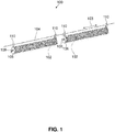
- FIG. 1 illustrates a luminaire assembly 100 according to an embodiment.
- the luminaire assembly 100 includes a plurality of luminaires 102, of which each luminaire 102 is mounted on a support 104.
- Each luminaire 102 is mounted on the support 104 by means of a support member 106; a luminaire 102 can include more than one support member 106 with which it is mounted on the support 104.
- two support members 106 can be used at both ends of the elongated luminaire to mount it on the support 104.
- teachings featured herein are applicable to other types of luminaires (i.e. other than elongated luminaires), and depending on the shape of a specified luminaire, one or more support members 106 can be used to mount the specified luminaire on the support 104.
- the support member 106 can be a plate that is mounted on an end of a luminaire 102.
- the support member 106 includes a substantially hook-shaped portion 110 having a channel 202, as shown in FIG. 2 ; the support 104 is mated with support member 106 at the channel 202 and secured by a tensioning member, as shall be described in greater detail below.
- the support member 106 can be a plastic part, or it can be made of metal. Moreover, it can be modular, i.e. it can be removably attached to an end plate of the luminaire 102, or it can be the end plate itself. Stated otherwise, the support member 106 can be a modular piece, or it can be a modular piece; in either case, it can be fabricated through an additive manufacturing process, for example.
- the support member 106 can include an interface for coupling it to the end of the luminaire 102.
- the support member 106 can include one or more holes, which can be threaded. These holes can be made to overlap with corresponding holes on the end of the luminaire 102, and the support member 106 can thus be fastened on the luminaire 102 using screws placed in the threaded holes.
- the support member 106 can further include a port 108 that is configured to let wiring or cabling pass through.
- the wiring can be electrical. For example, it can be used to power and/or control circuits and/or light sources included within the body of the luminaire 102. Generally, the wiring is used to provide a desired functionality to the luminaire 102.
- the support 104 can be a cable or a wire on which the one or more luminaires 102 is mounted. Further, the support 104 can extend in a direction 103, which can be substantially horizontal. However, as shall be described below, because the embodiments provide means to secure the luminaires 102 on the support 104, the support 104 need not be substantially horizontal, i.e. it can also be inclined, without risking the luminaires 102 sliding away from their initial positions, as they are locked securely in place.
- FIG. 2 illustrates a close-up view 200 of one of the luminaires 102.
- the support member 106 includes a substantially hook-shaped portion 110 that includes a channel 202 shaped to receive (or to mate with) the support 104.
- a tensioning member 204 secures the support 104 in the channel 202.
- the tensioning member 204 provides a restraint for the support 104 by generating a force (e.g. friction) to hold the support 104 in the channel 202.
- the tensioning member 204 can be a spring.
- the tensioning member 204 can be a bent spring wire.
- FIG. 3 illustrates a close-up view 300 of the support member 106.
- the channel 202 can be appropriately sized to accommodate the width of the support 104.
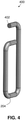
- a hole 302 is provided in which a portion 402 of the tensioning member 204 can be inserted; as can be seen in reference to FIG. 2 and the close-up view 400 of the tensioning member 204 shown in FIG. 4 .
- the portion 402 of the tensioning member 204 can be inserted in the hole 302 or snaked through it in order to provide a pivot point against which the tensioning member 204 can be actuated to secure the support 104 in the channel.
- the support member 106 further includes a plurality of holes 304, which can be part of an interface that is configured to couple the support member 106 with the end of the luminaire 102, as shown in FIG. 2 .
- the holes 304 can be threaded and screws inserted therein to secure the support member 106 onto the end of the luminaire 102.
- the support member 106 can further include a hole 306 that is sized appropriately to secure the port 108, as shown in FIGs. 1 and 2 .
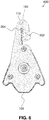
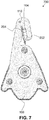
- FIGs. 5-8 illustrate a sequence of how the support 104 (shown end-on) may become seated in the support member 106 of a luminaire 102, as illustrated in FIG. 1 .
- a technician installing the luminaire 102 on the support 102 may begin by approaching the substantially hook-shaped portion 110 of the support member 106 to the support 104.
- FIG. 6 shows that by applying pressure on the support member 106 onto the support 104, the tensioning member 204 begins to move so that the support 104 approaches the channel 202 of the substantially hook-shaped portion 110.
- the support 104 is shown at the top of the channel 202; this is the position of the support 104 when the luminaire 102 is naturally suspended on the support 104 under the force of gravity.
- FIG. 8 shows an alternative position of the support 104 that illustrates how the support 104 may be prevented from sliding out of the channel 202 by a combination of the tension provided by the tensioning member 204, and the most curled portion of the substantially hook-shaped portion 110.
- detaching the luminaire 102 can be achieved by applying pressure to the luminaire and twisting it to unlock the support cable from the substantially hook-shaped member 110.
Landscapes
- Engineering & Computer Science (AREA)
- General Engineering & Computer Science (AREA)
- Non-Portable Lighting Devices Or Systems Thereof (AREA)
- Fastening Of Light Sources Or Lamp Holders (AREA)
Abstract
Description
- The present disclosure relates to luminaires. More particularly, the present disclosure relates to apparatuses for mounting luminaires on supports.
- In a wide variety of applications, such as in greenhouse lighting, one or more luminaires can be mounted on supports to position the luminaires over a particular area. In this arrangement, the illumination level over the area can be precisely regulated. However, assembling the luminaires on such supports may be cumbersome due to the complexity of the hardware needed for mounting. Moreover, in some instances, once mounted, the luminaires may move from their originally installed position by sliding off the supports, as typical mounting hardware do not offer adequate means for securing the luminaires on the support.
- There is a need to provide assemblies that allow luminaires to be easily installed on supports while allowing sturdy positioning of the luminaires on the supports. The embodiments featured herein help solve or mitigate these issues as well as other issues known in the art.
- For example, some embodiments of the instant disclosure provide a method and/or an assembly for safe and quick mounting of a luminaire on a support such as a cable or a wire. The luminaire can include an end part that includes a hook-shaped member and a retention force element, such as a tensioning member. The end part prevents the release of the support from the hook-shaped member when pressure is applied to the luminaire from any given direction. Moreover, the retention force element can generate pressure and friction on the support to inhibit the sliding of the hook-shaped member on the support, thereby allowing the support to be placed in a wide variety of positions, without risking the luminaire moving away relative to its original mounted position.
- One exemplary embodiment provides a mechanism for mounting a luminaire on a support. The mechanism includes a plate adapted to couple with an end of the luminaire, the plate includes a support member adapted to mate with the support. The mechanism further includes a tensioning member adapted to couple with the support member to secure the support in a channel of the support member.
- Another exemplary embodiment provides a luminaire assembly including a luminaire mounted on a support. The luminaire assembly includes a mechanism for mounting the luminaire on the support. The mechanism includes a plate adapted to couple with an end of the luminaire, the plate includes a support member adapted to mate with the support. The mechanism further includes a tensioning member adapted to couple with the support member to secure the support in a channel of the support member.
- Additional features, modes of operations, advantages, and other aspects of various embodiments are described below with reference to the accompanying drawings. It is noted that the present disclosure is not limited to the specific embodiments described herein. These embodiments are presented for illustrative purposes. Additional embodiments, or modifications of the embodiments disclosed, will be readily apparent to persons skilled in the relevant art(s) based on the teachings provided.
- Illustrative embodiments may take form in various components and arrangements of components. Illustrative embodiments are shown in the accompanying drawings, throughout which like reference numerals may indicate corresponding or similar parts in the various drawings. The drawings are for purposes of illustrating the embodiments and are not to be construed as limiting the disclosure. Given the following enabling description of the drawings, the novel aspects of the present disclosure should become evident to a person of ordinary skill in the relevant art(s).
-
FIG. 1 illustrates a luminaire assembly in accordance with various aspects described herein. -
FIG. 2 shows a close-up view of a luminaire in accordance with various aspects described herein. -
FIG. 3 shows a close-up view of a support member in accordance with various aspects described herein. -
FIG. 4 illustrates a close-up view of a tensioning member in accordance with various aspects described herein. -
FIG. 5 illustrates a cross-sectional view of a luminaire assembly in accordance with various aspects described herein. -
FIG. 6 illustrates a cross-sectional view of a luminaire assembly in accordance with various aspects described herein -
FIG. 7 illustrates a cross-sectional view of a luminaire assembly in accordance with various aspects described herein. -
FIG. 8 illustrates a cross-sectional view of a luminaire assembly in accordance with various aspects described herein. - While the illustrative embodiments are described herein for particular applications, it should be understood that the present disclosure is not limited thereto. Those skilled in the art and with access to the teachings provided herein will recognize additional applications, modifications, and embodiments within the scope thereof and additional fields in which the present disclosure would be of significant utility.
-
FIG. 1 illustrates aluminaire assembly 100 according to an embodiment. Theluminaire assembly 100 includes a plurality ofluminaires 102, of which eachluminaire 102 is mounted on asupport 104. Eachluminaire 102 is mounted on thesupport 104 by means of asupport member 106; aluminaire 102 can include more than onesupport member 106 with which it is mounted on thesupport 104. - For example, for an elongated luminaire such as the ones shown in
FIG. 1 , twosupport members 106 can be used at both ends of the elongated luminaire to mount it on thesupport 104. Generally, the teachings featured herein are applicable to other types of luminaires (i.e. other than elongated luminaires), and depending on the shape of a specified luminaire, one ormore support members 106 can be used to mount the specified luminaire on thesupport 104. - The
support member 106 can be a plate that is mounted on an end of a luminaire 102. In some exemplary embodiments, thesupport member 106 includes a substantially hook-shaped portion 110 having achannel 202, as shown inFIG. 2 ; thesupport 104 is mated withsupport member 106 at thechannel 202 and secured by a tensioning member, as shall be described in greater detail below. - Without loss of generality, the
support member 106 can be a plastic part, or it can be made of metal. Moreover, it can be modular, i.e. it can be removably attached to an end plate of theluminaire 102, or it can be the end plate itself. Stated otherwise, thesupport member 106 can be a modular piece, or it can be a modular piece; in either case, it can be fabricated through an additive manufacturing process, for example. - In some embodiments, the
support member 106 can include an interface for coupling it to the end of theluminaire 102. For example, thesupport member 106 can include one or more holes, which can be threaded. These holes can be made to overlap with corresponding holes on the end of theluminaire 102, and thesupport member 106 can thus be fastened on theluminaire 102 using screws placed in the threaded holes. - The
support member 106 can further include aport 108 that is configured to let wiring or cabling pass through. The wiring can be electrical. For example, it can be used to power and/or control circuits and/or light sources included within the body of theluminaire 102. Generally, the wiring is used to provide a desired functionality to theluminaire 102. - The
support 104 can be a cable or a wire on which the one ormore luminaires 102 is mounted. Further, thesupport 104 can extend in adirection 103, which can be substantially horizontal. However, as shall be described below, because the embodiments provide means to secure theluminaires 102 on thesupport 104, thesupport 104 need not be substantially horizontal, i.e. it can also be inclined, without risking theluminaires 102 sliding away from their initial positions, as they are locked securely in place. -
FIG. 2 illustrates a close-up view 200 of one of theluminaires 102. As previously mentioned, thesupport member 106 includes a substantially hook-shaped portion 110 that includes achannel 202 shaped to receive (or to mate with) thesupport 104. A tensioningmember 204 secures thesupport 104 in thechannel 202. In other words, the tensioningmember 204 provides a restraint for thesupport 104 by generating a force (e.g. friction) to hold thesupport 104 in thechannel 202. In some embodiments, the tensioningmember 204 can be a spring. In yet other embodiments, the tensioningmember 204 can be a bent spring wire. -
FIG. 3 illustrates a close-upview 300 of thesupport member 106. In the substantially hook-shapedportion 110, thechannel 202 can be appropriately sized to accommodate the width of thesupport 104. Further, to secure thesupport 104 in thechannel 202, ahole 302 is provided in which aportion 402 of the tensioningmember 204 can be inserted; as can be seen in reference toFIG. 2 and the close-upview 400 of the tensioningmember 204 shown inFIG. 4 . - The
portion 402 of the tensioningmember 204 can be inserted in thehole 302 or snaked through it in order to provide a pivot point against which thetensioning member 204 can be actuated to secure thesupport 104 in the channel. In some embodiments, there can be more than onehole 302 on the substantially hook-shapedportion 110, thus providing a reconfigurable mechanism for adjusting the tensioningmember 204 to accommodate supports of different sizes (e.g. of different diameters). - The
support member 106 further includes a plurality ofholes 304, which can be part of an interface that is configured to couple thesupport member 106 with the end of theluminaire 102, as shown inFIG. 2 . Theholes 304 can be threaded and screws inserted therein to secure thesupport member 106 onto the end of theluminaire 102. Thesupport member 106 can further include ahole 306 that is sized appropriately to secure theport 108, as shown inFIGs. 1 and2 . - Having set forth various embodiments, various positions of the
support member 106 and thetensioning member 204 during mounting are described with respect to the close-upviews FIGs. 5 ,6 ,7 , and8 , respectively. Specifically,FIGs. 5-8 illustrate a sequence of how the support 104 (shown end-on) may become seated in thesupport member 106 of aluminaire 102, as illustrated inFIG. 1 . InFIG. 5 , a technician installing theluminaire 102 on thesupport 102 may begin by approaching the substantially hook-shapedportion 110 of thesupport member 106 to thesupport 104. - As shown in
FIG. 6 , by applying pressure on thesupport member 106 onto thesupport 104, the tensioningmember 204 begins to move so that thesupport 104 approaches thechannel 202 of the substantially hook-shapedportion 110. InFIG. 7 , thesupport 104 is shown at the top of thechannel 202; this is the position of thesupport 104 when theluminaire 102 is naturally suspended on thesupport 104 under the force of gravity.FIG. 8 , shows an alternative position of thesupport 104 that illustrates how thesupport 104 may be prevented from sliding out of thechannel 202 by a combination of the tension provided by the tensioningmember 204, and the most curled portion of the substantially hook-shapedportion 110. - As such, in the embodiments, the application of a uniaxial force would not be able to dislodge the
support 104 from thechannel 202. Moreover, detaching theluminaire 102 can be achieved by applying pressure to the luminaire and twisting it to unlock the support cable from the substantially hook-shapedmember 110. - Those skilled in the relevant art(s) will appreciate that various adaptations and modifications of the embodiments described above can be configured without departing from the scope and spirit of the disclosure. Therefore, it is to be understood that, within the scope of the appended claims, the disclosure may be practiced other than as specifically described herein.
- Various aspects and embodiments of the present invention are defined by the following clauses:
- 1. A mechanism for mounting a luminaire on a support, the mechanism comprising:
- a plate adapted to couple with an end of the luminaire, the plate including a support member adapted to mate with the support; and
- a tensioning member adapted to couple with the support member to secure the support in a channel region of the support member.
- 2. The mechanism of clause 1, wherein the support is one of a cable and a wire.
- 3. The mechanism of clause 1, wherein the support member includes a substantially hook-shaped portion.
- 4. The mechanism of clause 1, wherein the support member is removably attached on the plate.
- 5. The mechanism of clause 1, wherein the plate includes an interface configured for coupling with the end of the luminaire.
- 6. The mechanism of clause 5, wherein the interface includes a threaded hole.
- 7. The mechanism of clause 1, wherein the plate includes a port configured for receiving electrical wiring.
- 8. The mechanism of clause 1, wherein the tensioning member includes a spring.
- 9. The mechanism of
clause 8, wherein the spring is a bent spring wire. - 10. The mechanism of clause 1, wherein the plate includes a hole configured for receiving a portion of the tensioning member.
- 11. A luminaire assembly comprising a luminaire mounted on a support, the luminaire assembly comprising:
- a mechanism configured for mounting the luminaire on the support, wherein the mechanism includes:
- a plate adapted to couple with an end of the luminaire, the plate including a support member adapted to mate with the support; and
- a tensioning member adapted to couple with the support member to secure the support in a channel region of the support member.
- a mechanism configured for mounting the luminaire on the support, wherein the mechanism includes:
- 12. The luminaire assembly of clause 11, wherein the support is a cable.
- 13. The luminaire assembly of clause 11, wherein the support member includes a substantially hook-shaped portion.
- 14. The luminaire assembly of clause 11, wherein support member is removably attached on the plate.
- 15. The luminaire assembly of clause 11, wherein the plate includes an interface configured for coupling with the end of the luminaire.
- 16. The luminaire assembly of clause 15, wherein the interface includes a threaded hole.
- 17. The luminaire assembly of clause 11, wherein the plate includes a port configured for receiving electrical wiring.
- 18. The luminaire assembly of clause 11, wherein the tensioning member includes a spring.
- 19. The luminaire assembly of clause 18, wherein the spring is a bent spring wire.
- 20. The luminaire assembly of clause 11, wherein the plate includes a hole configured for receiving a portion of the tensioning member.
Claims (15)
- A mechanism for mounting a luminaire (102) on a support (104), the mechanism comprising:a plate adapted to couple with an end of the luminaire (102), the plate including a support member (106) adapted to mate with the support (104); anda tensioning member (204) adapted to couple with the support (104) member to secure the support (104) in a channel region of the support member (106).
- The mechanism of claim 1, wherein the support (104) is one of a cable and a wire.
- The mechanism of claim 1 or claim 2, wherein the support member (106) includes a substantially hook-shaped portion (110).
- The mechanism of any preceding claim, wherein the support (104) member is removably attached on the plate.
- The mechanism of any preceding claim, wherein the plate includes an interface (302) configured for coupling with the end of the luminaire (102).
- The mechanism of claim 5, wherein the interface (302) includes a threaded hole.
- The mechanism of any preceding claim, wherein the plate includes a port (108) configured for receiving electrical wiring.
- The mechanism of any preceding claim, wherein the tensioning member (204) includes a spring.
- The mechanism of any preceding claim, wherein the plate includes a hole (304) configured for receiving a portion of the tensioning member (204).
- A luminaire assembly (100) comprising a luminaire (102) mounted on a support (104), the luminaire assembly (100) comprising:a mechanism configured for mounting the luminaire (102) on the support (104), wherein the mechanism includes:a plate adapted to couple with an end of the luminaire (102), the plate including a support member (106) adapted to mate with the support (104); anda tensioning member (204) adapted to couple with the support member (106) to secure the support (104) in a channel region of the support member (106).
- The luminaire assembly (100) of claim 10, wherein the support (104) is a cable.
- The luminaire assembly (100) of claim 10 or claim 11, wherein the support member (106) includes a substantially hook-shaped portion (110).
- The luminaire assembly (100) of any of claims 10 to 12, wherein support member (106) is removably attached on the plate.
- The luminaire assembly (100) of any of claims 10 to 13, wherein the plate includes an interface configured for coupling with the end of the luminaire (102).
- The luminaire assembly (100) of any of claims 10 to 14, wherein the plate includes a hole (302) configured for receiving a portion of the tensioning member (204).
Applications Claiming Priority (2)
| Application Number | Priority Date | Filing Date | Title |
|---|---|---|---|
| US201662312047P | 2016-03-23 | 2016-03-23 | |
| US15/343,822 US10690324B2 (en) | 2016-03-23 | 2016-11-04 | Apparatus for mounting a luminaire on a support |
Publications (1)
| Publication Number | Publication Date |
|---|---|
| EP3222909A1 true EP3222909A1 (en) | 2017-09-27 |
Family
ID=58412949
Family Applications (1)
| Application Number | Title | Priority Date | Filing Date |
|---|---|---|---|
| EP17162650.0A Pending EP3222909A1 (en) | 2016-03-23 | 2017-03-23 | Apparatus for mounting a luminaire on a support |
Country Status (3)
| Country | Link |
|---|---|
| US (1) | US10690324B2 (en) |
| EP (1) | EP3222909A1 (en) |
| CN (1) | CN107228341B (en) |
Cited By (1)
| Publication number | Priority date | Publication date | Assignee | Title |
|---|---|---|---|---|
| WO2024213418A1 (en) * | 2023-04-11 | 2024-10-17 | Signify Holding B.V. | Lighting system to provide a light in for instance a stable, a barn, or a poultry house |
Families Citing this family (3)
| Publication number | Priority date | Publication date | Assignee | Title |
|---|---|---|---|---|
| USD893085S1 (en) * | 2019-05-27 | 2020-08-11 | Shenzhen Jindian Electronic Technology Co., Ltd. | Lamp |
| CN112303536A (en) * | 2020-10-23 | 2021-02-02 | 江苏精仪达科技有限公司 | Complex light suspension device |
| US12292182B1 (en) * | 2024-07-30 | 2025-05-06 | Signcomplex Limited | Lamp with replaceable power supply module |
Citations (8)
| Publication number | Priority date | Publication date | Assignee | Title |
|---|---|---|---|---|
| FR985166A (en) * | 1949-04-25 | 1951-07-16 | Portable articulated lamppost | |
| DE2748606A1 (en) * | 1977-10-29 | 1979-05-03 | Hermann Abke | Light fitting mounting hanging from rope - has hooked links formed by arms of U=shaped bracket |
| US4841420A (en) * | 1988-06-20 | 1989-06-20 | Woodhead Industries, Inc. | String lights for construction sites |
| WO1998004867A1 (en) * | 1996-07-30 | 1998-02-05 | Light & Sound Design, Ltd. | A lamp-holding hook clamp and connector keyway |
| FR2913482A1 (en) * | 2007-03-05 | 2008-09-12 | Hollux Sarl | Troffer for use in lighting field, has caisson or sheath presenting supply beam using external electrical apparatus, where beam is connected to connector accessible from outside caisson for supplying apparatus |
| EP2163815A2 (en) * | 2008-09-16 | 2010-03-17 | Beghelli S.p.A. | Watertight seal lighting equipment |
| US20110116254A1 (en) * | 2009-11-16 | 2011-05-19 | Goal Zero Llc | Lighting apparatus; components thereof and assemblies incorporating the same |
| US20130044483A1 (en) * | 2009-11-18 | 2013-02-21 | Ondal Medical Systems Gmbh | Lighting unit |
Family Cites Families (12)
| Publication number | Priority date | Publication date | Assignee | Title |
|---|---|---|---|---|
| US5282600A (en) | 1991-09-30 | 1994-02-01 | Peerless Lighting Corporation | Universal quick connect hanger for suspending a lighting system |
| US5743627A (en) * | 1997-02-25 | 1998-04-28 | Casteel; Joseph M. | Lighting fixture |
| JP3148975B2 (en) * | 1997-06-16 | 2001-03-26 | 株式会社サンテック | securing bracket |
| US6283618B1 (en) * | 1999-06-07 | 2001-09-04 | Lsi Industries Inc. | Luminaire assembly |
| WO2002089559A2 (en) | 2001-05-10 | 2002-11-14 | Michiel Vastgoed En Management B.V. | Apparatus for assimilation lighting as well as fixing system and method for installation thereof in a greenhouse |
| KR20080032990A (en) * | 2006-10-12 | 2008-04-16 | 삼성전자주식회사 | Backlight assembly and liquid crystal display including the same |
| CN200986162Y (en) * | 2006-12-27 | 2007-12-05 | 浙江大学 | Portable clip lamp |
| CN201892171U (en) * | 2010-10-29 | 2011-07-06 | 东莞巨扬电器有限公司 | An easy-to-place work light |
| CN102352965A (en) * | 2011-07-13 | 2012-02-15 | 王成 | Electric torch for bicycle |
| US8794804B2 (en) * | 2011-10-18 | 2014-08-05 | Orion Energy Systems, Inc. | System and method for supporting and leveling a light fixture |
| CN103277751A (en) * | 2013-06-19 | 2013-09-04 | 苏州信亚科技有限公司 | LED (light-emitting diode) lamp mounting bracket |
| US9057508B1 (en) * | 2014-10-22 | 2015-06-16 | Codeshelf | Modular hanging lasers to enable real-time control in a distribution center |
-
2016
- 2016-11-04 US US15/343,822 patent/US10690324B2/en active Active
-
2017
- 2017-03-23 EP EP17162650.0A patent/EP3222909A1/en active Pending
- 2017-03-23 CN CN201710177659.8A patent/CN107228341B/en active Active
Patent Citations (8)
| Publication number | Priority date | Publication date | Assignee | Title |
|---|---|---|---|---|
| FR985166A (en) * | 1949-04-25 | 1951-07-16 | Portable articulated lamppost | |
| DE2748606A1 (en) * | 1977-10-29 | 1979-05-03 | Hermann Abke | Light fitting mounting hanging from rope - has hooked links formed by arms of U=shaped bracket |
| US4841420A (en) * | 1988-06-20 | 1989-06-20 | Woodhead Industries, Inc. | String lights for construction sites |
| WO1998004867A1 (en) * | 1996-07-30 | 1998-02-05 | Light & Sound Design, Ltd. | A lamp-holding hook clamp and connector keyway |
| FR2913482A1 (en) * | 2007-03-05 | 2008-09-12 | Hollux Sarl | Troffer for use in lighting field, has caisson or sheath presenting supply beam using external electrical apparatus, where beam is connected to connector accessible from outside caisson for supplying apparatus |
| EP2163815A2 (en) * | 2008-09-16 | 2010-03-17 | Beghelli S.p.A. | Watertight seal lighting equipment |
| US20110116254A1 (en) * | 2009-11-16 | 2011-05-19 | Goal Zero Llc | Lighting apparatus; components thereof and assemblies incorporating the same |
| US20130044483A1 (en) * | 2009-11-18 | 2013-02-21 | Ondal Medical Systems Gmbh | Lighting unit |
Cited By (1)
| Publication number | Priority date | Publication date | Assignee | Title |
|---|---|---|---|---|
| WO2024213418A1 (en) * | 2023-04-11 | 2024-10-17 | Signify Holding B.V. | Lighting system to provide a light in for instance a stable, a barn, or a poultry house |
Also Published As
| Publication number | Publication date |
|---|---|
| US20170276333A1 (en) | 2017-09-28 |
| CN107228341A (en) | 2017-10-03 |
| CN107228341B (en) | 2021-03-12 |
| US10690324B2 (en) | 2020-06-23 |
Similar Documents
| Publication | Publication Date | Title |
|---|---|---|
| US10690324B2 (en) | Apparatus for mounting a luminaire on a support | |
| US6843581B2 (en) | Luminaire pendant system | |
| EP2045512B1 (en) | Component holder for attachment in a panel | |
| CN108808595B (en) | Tool-free cable installation device | |
| US9903571B2 (en) | Adjustable mounting torsion spring receiver assembly for LED retrofit | |
| KR101647353B1 (en) | Illumination module with one touch combination structure | |
| US8057077B2 (en) | Support device | |
| KR101674649B1 (en) | Ceiling coupled device for lighting apparatus | |
| US10584864B2 (en) | Downlight lighting assembly | |
| JP2019521302A (en) | Improvement on or in connection device | |
| UA124571C2 (en) | INSULATOR | |
| US10393329B2 (en) | Light fixture mechanical interconnect with rotative joining | |
| CN116753491A (en) | Suspension assembly for suspending a suspended light fixture from a ceiling | |
| EP3115686A1 (en) | Engagement system and method for mounting lighting fixture | |
| KR20180113816A (en) | Apparatus of fixing safety rope for hanging-bolt | |
| CN110635413B (en) | Multi-channel cable fixing device with embedded nuts | |
| EP1419324A1 (en) | Suspending equipment | |
| EP2247881B1 (en) | A clamp assembly for securing a cable to a structural support | |
| US9541265B2 (en) | Mounting device for lighting sources and associated method | |
| KR101537804B1 (en) | An led lighting apparatus | |
| US10808868B2 (en) | Apparatus to assemble cable mounts | |
| KR100514842B1 (en) | fixing clip for wiring | |
| DK3021440T3 (en) | CONNECTOR FOR ELECTRICAL DEVICE | |
| JP6192772B2 (en) | Lighting apparatus and method of attaching the lighting apparatus | |
| KR20150074869A (en) | Down light device |
Legal Events
| Date | Code | Title | Description |
|---|---|---|---|
| PUAI | Public reference made under article 153(3) epc to a published international application that has entered the european phase |
Free format text: ORIGINAL CODE: 0009012 |
|
| STAA | Information on the status of an ep patent application or granted ep patent |
Free format text: STATUS: THE APPLICATION HAS BEEN PUBLISHED |
|
| AK | Designated contracting states |
Kind code of ref document: A1 Designated state(s): AL AT BE BG CH CY CZ DE DK EE ES FI FR GB GR HR HU IE IS IT LI LT LU LV MC MK MT NL NO PL PT RO RS SE SI SK SM TR |
|
| AX | Request for extension of the european patent |
Extension state: BA ME |
|
| STAA | Information on the status of an ep patent application or granted ep patent |
Free format text: STATUS: REQUEST FOR EXAMINATION WAS MADE |
|
| 17P | Request for examination filed |
Effective date: 20180327 |
|
| RBV | Designated contracting states (corrected) |
Designated state(s): AL AT BE BG CH CY CZ DE DK EE ES FI FR GB GR HR HU IE IS IT LI LT LU LV MC MK MT NL NO PL PT RO RS SE SI SK SM TR |
|
| STAA | Information on the status of an ep patent application or granted ep patent |
Free format text: STATUS: EXAMINATION IS IN PROGRESS |
|
| 17Q | First examination report despatched |
Effective date: 20180618 |
|
| RAP3 | Party data changed (applicant data changed or rights of an application transferred) |
Owner name: GE LIGHTING SOLUTIONS, LLC |
|
| RAP3 | Party data changed (applicant data changed or rights of an application transferred) |
Owner name: CURRENT LIGHTING SOLUTIONS, LLC |
|
| P01 | Opt-out of the competence of the unified patent court (upc) registered |
Effective date: 20230518 |
|
| GRAP | Despatch of communication of intention to grant a patent |
Free format text: ORIGINAL CODE: EPIDOSNIGR1 |
|
| STAA | Information on the status of an ep patent application or granted ep patent |
Free format text: STATUS: GRANT OF PATENT IS INTENDED |
|
| INTG | Intention to grant announced |
Effective date: 20251212 |
|
| GRAS | Grant fee paid |
Free format text: ORIGINAL CODE: EPIDOSNIGR3 |
|
| GRAA | (expected) grant |
Free format text: ORIGINAL CODE: 0009210 |
|
| STAA | Information on the status of an ep patent application or granted ep patent |
Free format text: STATUS: THE PATENT HAS BEEN GRANTED |