EP3222871A1 - Disc brake device - Google Patents
Disc brake device Download PDFInfo
- Publication number
- EP3222871A1 EP3222871A1 EP15861620.1A EP15861620A EP3222871A1 EP 3222871 A1 EP3222871 A1 EP 3222871A1 EP 15861620 A EP15861620 A EP 15861620A EP 3222871 A1 EP3222871 A1 EP 3222871A1
- Authority
- EP
- European Patent Office
- Prior art keywords
- slide portion
- disc brake
- gap
- brake apparatus
- slide
- Prior art date
- Legal status (The legal status is an assumption and is not a legal conclusion. Google has not performed a legal analysis and makes no representation as to the accuracy of the status listed.)
- Withdrawn
Links
- 230000005540 biological transmission Effects 0.000 claims abstract description 50
- 210000000078 claw Anatomy 0.000 claims description 23
- 239000000470 constituent Substances 0.000 claims description 8
- 230000000694 effects Effects 0.000 description 3
- 239000000463 material Substances 0.000 description 3
- 229910000831 Steel Inorganic materials 0.000 description 2
- 238000004873 anchoring Methods 0.000 description 2
- 238000010276 construction Methods 0.000 description 2
- 239000010959 steel Substances 0.000 description 2
- 206010016275 Fear Diseases 0.000 description 1
- 230000015572 biosynthetic process Effects 0.000 description 1
- 239000000428 dust Substances 0.000 description 1
- 230000001960 triggered effect Effects 0.000 description 1
- 230000003245 working effect Effects 0.000 description 1
Images



Classifications
-
- F—MECHANICAL ENGINEERING; LIGHTING; HEATING; WEAPONS; BLASTING
- F16—ENGINEERING ELEMENTS AND UNITS; GENERAL MEASURES FOR PRODUCING AND MAINTAINING EFFECTIVE FUNCTIONING OF MACHINES OR INSTALLATIONS; THERMAL INSULATION IN GENERAL
- F16D—COUPLINGS FOR TRANSMITTING ROTATION; CLUTCHES; BRAKES
- F16D65/00—Parts or details
- F16D65/02—Braking members; Mounting thereof
- F16D65/04—Bands, shoes or pads; Pivots or supporting members therefor
- F16D65/092—Bands, shoes or pads; Pivots or supporting members therefor for axially-engaging brakes, e.g. disc brakes
- F16D65/095—Pivots or supporting members therefor
-
- F—MECHANICAL ENGINEERING; LIGHTING; HEATING; WEAPONS; BLASTING
- F16—ENGINEERING ELEMENTS AND UNITS; GENERAL MEASURES FOR PRODUCING AND MAINTAINING EFFECTIVE FUNCTIONING OF MACHINES OR INSTALLATIONS; THERMAL INSULATION IN GENERAL
- F16D—COUPLINGS FOR TRANSMITTING ROTATION; CLUTCHES; BRAKES
- F16D55/00—Brakes with substantially-radial braking surfaces pressed together in axial direction, e.g. disc brakes
- F16D55/02—Brakes with substantially-radial braking surfaces pressed together in axial direction, e.g. disc brakes with axially-movable discs or pads pressed against axially-located rotating members
- F16D55/22—Brakes with substantially-radial braking surfaces pressed together in axial direction, e.g. disc brakes with axially-movable discs or pads pressed against axially-located rotating members by clamping an axially-located rotating disc between movable braking members, e.g. movable brake discs or brake pads
- F16D55/224—Brakes with substantially-radial braking surfaces pressed together in axial direction, e.g. disc brakes with axially-movable discs or pads pressed against axially-located rotating members by clamping an axially-located rotating disc between movable braking members, e.g. movable brake discs or brake pads with a common actuating member for the braking members
- F16D55/225—Brakes with substantially-radial braking surfaces pressed together in axial direction, e.g. disc brakes with axially-movable discs or pads pressed against axially-located rotating members by clamping an axially-located rotating disc between movable braking members, e.g. movable brake discs or brake pads with a common actuating member for the braking members the braking members being brake pads
- F16D55/226—Brakes with substantially-radial braking surfaces pressed together in axial direction, e.g. disc brakes with axially-movable discs or pads pressed against axially-located rotating members by clamping an axially-located rotating disc between movable braking members, e.g. movable brake discs or brake pads with a common actuating member for the braking members the braking members being brake pads in which the common actuating member is moved axially, e.g. floating caliper disc brakes
- F16D55/2265—Brakes with substantially-radial braking surfaces pressed together in axial direction, e.g. disc brakes with axially-movable discs or pads pressed against axially-located rotating members by clamping an axially-located rotating disc between movable braking members, e.g. movable brake discs or brake pads with a common actuating member for the braking members the braking members being brake pads in which the common actuating member is moved axially, e.g. floating caliper disc brakes the axial movement being guided by one or more pins engaging bores in the brake support or the brake housing
- F16D55/22655—Constructional details of guide pins
-
- F—MECHANICAL ENGINEERING; LIGHTING; HEATING; WEAPONS; BLASTING
- F16—ENGINEERING ELEMENTS AND UNITS; GENERAL MEASURES FOR PRODUCING AND MAINTAINING EFFECTIVE FUNCTIONING OF MACHINES OR INSTALLATIONS; THERMAL INSULATION IN GENERAL
- F16D—COUPLINGS FOR TRANSMITTING ROTATION; CLUTCHES; BRAKES
- F16D55/00—Brakes with substantially-radial braking surfaces pressed together in axial direction, e.g. disc brakes
- F16D55/02—Brakes with substantially-radial braking surfaces pressed together in axial direction, e.g. disc brakes with axially-movable discs or pads pressed against axially-located rotating members
- F16D55/22—Brakes with substantially-radial braking surfaces pressed together in axial direction, e.g. disc brakes with axially-movable discs or pads pressed against axially-located rotating members by clamping an axially-located rotating disc between movable braking members, e.g. movable brake discs or brake pads
- F16D55/224—Brakes with substantially-radial braking surfaces pressed together in axial direction, e.g. disc brakes with axially-movable discs or pads pressed against axially-located rotating members by clamping an axially-located rotating disc between movable braking members, e.g. movable brake discs or brake pads with a common actuating member for the braking members
- F16D55/225—Brakes with substantially-radial braking surfaces pressed together in axial direction, e.g. disc brakes with axially-movable discs or pads pressed against axially-located rotating members by clamping an axially-located rotating disc between movable braking members, e.g. movable brake discs or brake pads with a common actuating member for the braking members the braking members being brake pads
- F16D55/226—Brakes with substantially-radial braking surfaces pressed together in axial direction, e.g. disc brakes with axially-movable discs or pads pressed against axially-located rotating members by clamping an axially-located rotating disc between movable braking members, e.g. movable brake discs or brake pads with a common actuating member for the braking members the braking members being brake pads in which the common actuating member is moved axially, e.g. floating caliper disc brakes
-
- F—MECHANICAL ENGINEERING; LIGHTING; HEATING; WEAPONS; BLASTING
- F16—ENGINEERING ELEMENTS AND UNITS; GENERAL MEASURES FOR PRODUCING AND MAINTAINING EFFECTIVE FUNCTIONING OF MACHINES OR INSTALLATIONS; THERMAL INSULATION IN GENERAL
- F16D—COUPLINGS FOR TRANSMITTING ROTATION; CLUTCHES; BRAKES
- F16D65/00—Parts or details
- F16D65/005—Components of axially engaging brakes not otherwise provided for
- F16D65/0068—Brake calipers
-
- F—MECHANICAL ENGINEERING; LIGHTING; HEATING; WEAPONS; BLASTING
- F16—ENGINEERING ELEMENTS AND UNITS; GENERAL MEASURES FOR PRODUCING AND MAINTAINING EFFECTIVE FUNCTIONING OF MACHINES OR INSTALLATIONS; THERMAL INSULATION IN GENERAL
- F16D—COUPLINGS FOR TRANSMITTING ROTATION; CLUTCHES; BRAKES
- F16D65/00—Parts or details
- F16D65/005—Components of axially engaging brakes not otherwise provided for
- F16D65/0087—Brake housing guide members, e.g. caliper pins; Accessories therefor, e.g. dust boots
-
- F—MECHANICAL ENGINEERING; LIGHTING; HEATING; WEAPONS; BLASTING
- F16—ENGINEERING ELEMENTS AND UNITS; GENERAL MEASURES FOR PRODUCING AND MAINTAINING EFFECTIVE FUNCTIONING OF MACHINES OR INSTALLATIONS; THERMAL INSULATION IN GENERAL
- F16D—COUPLINGS FOR TRANSMITTING ROTATION; CLUTCHES; BRAKES
- F16D65/00—Parts or details
- F16D65/02—Braking members; Mounting thereof
-
- F—MECHANICAL ENGINEERING; LIGHTING; HEATING; WEAPONS; BLASTING
- F16—ENGINEERING ELEMENTS AND UNITS; GENERAL MEASURES FOR PRODUCING AND MAINTAINING EFFECTIVE FUNCTIONING OF MACHINES OR INSTALLATIONS; THERMAL INSULATION IN GENERAL
- F16D—COUPLINGS FOR TRANSMITTING ROTATION; CLUTCHES; BRAKES
- F16D55/00—Brakes with substantially-radial braking surfaces pressed together in axial direction, e.g. disc brakes
- F16D2055/0004—Parts or details of disc brakes
- F16D2055/0008—Brake supports
-
- F—MECHANICAL ENGINEERING; LIGHTING; HEATING; WEAPONS; BLASTING
- F16—ENGINEERING ELEMENTS AND UNITS; GENERAL MEASURES FOR PRODUCING AND MAINTAINING EFFECTIVE FUNCTIONING OF MACHINES OR INSTALLATIONS; THERMAL INSULATION IN GENERAL
- F16D—COUPLINGS FOR TRANSMITTING ROTATION; CLUTCHES; BRAKES
- F16D55/00—Brakes with substantially-radial braking surfaces pressed together in axial direction, e.g. disc brakes
- F16D2055/0004—Parts or details of disc brakes
- F16D2055/0016—Brake calipers
-
- F—MECHANICAL ENGINEERING; LIGHTING; HEATING; WEAPONS; BLASTING
- F16—ENGINEERING ELEMENTS AND UNITS; GENERAL MEASURES FOR PRODUCING AND MAINTAINING EFFECTIVE FUNCTIONING OF MACHINES OR INSTALLATIONS; THERMAL INSULATION IN GENERAL
- F16D—COUPLINGS FOR TRANSMITTING ROTATION; CLUTCHES; BRAKES
- F16D65/00—Parts or details
- F16D65/005—Components of axially engaging brakes not otherwise provided for
- F16D65/0056—Brake supports
Definitions
- the present invention relates to a disc brake apparatus.
- disc brake apparatuses As a disc brake apparatus incorporating a floating caliper in which braking torque of an outer pad is borne via pins which are fixed to a support member, disc brake apparatuses are known which are configured as disclosed in Patent Document 1 and Patent Document 2.
- the disc brake apparatus disclosed in Patent Document 1 adopts a configuration in which an inner pad is supported by a support member and an outer pad is supported by anchor pins.
- the outer pad is supported by the anchor pins being inserted through through holes provided in lug portions of a pressure plate which makes up the outer pad.
- the disc brake apparatus disclosed in Patent Document 2 adopts a configuration in which an inner pad and an outer pad are both supported by anchor pins.
- the supporting form of the pads by the anchor pins is similar to that of the configuration disclosed in Patent Document 1, and the anchor pins are inserted through through holes provided in a pressure plate.
- the disc brake apparatus configured in this way, when the brakes are applied, pulling force, pushing force or both the pulling force and the pushing force are applied to the inner pad and the outer pad.
- the configuration of the support members is simplified, which can realize the reduction in both size and weight of the disc brake apparatuses as a whole.
- the invention has been made in these situations and an object thereof is to provide a disc brake apparatus which can prevent pins and a support member from being deformed while realizing the bearing of braking torque by the pins by solving the problem described above and simplifying the configuration of the support member.
- the disc brake apparatus configured as described heretofore, even in the event that the configuration of the support member is simplified and that the torque bearing construction is adopted in which the braking torque is borne by the pins, it is possible to prevent the deformation of the pins and the support member. Thus, it is also possible to suppress the occurrence of eccentric wear that would otherwise be caused by the deformed pins or support member.
- the disc brake apparatus 10 has a support member 12, slide members 22 which are supported by this support member 12, and a caliper 30 which is supported via the slide members 22.
- the support member 12 is fixed to a vehicle body and plays a role of supporting the caliper 30 slidably.
- the support member 12 is disposed between a cylinder portion 32 (an inboard body) and a claw portion 36 (an outboard body) of the caliper 30 (in other words, within a frame of the caliper 30).
- the support member 12 includes, at least, anchors 14a, 14b, a bridge 16, mounting holes 18 and slide member mounting portions 20 (refer to Fig. 5 ).
- the anchors 14a, 14b are disposed on a rotating rotor entrance side and a rotating rotor exit side of the support member 12, respectively, where a rotor 60 enters and exits when it rotates.
- the anchors 14a, 14b support an inner pad 46 and function as torque bearing portions which bear force which attempts to rotate the inner pad 46 together with the rotor 60 when the brakes are applied.
- the inner pad 46 is made up of a pressure plate 48 which is made of a sheet of steel and a lining 50 which is a frictional member. The inner pad 46 is supported on the support member 12 via part of the pressure plate 48.
- the bridge 16 is a connecting member which connects together the anchor 14a which is disposed on the rotating rotor entrance side and the anchor 14b which is disposed on the rotating rotor exit side of the support member 12 where the rotor 60 enters and exits when it rotates.
- the mounting holes 18 are holes which are provided in connecting portions between the anchors 14a, 14b and the bridge 16 for passage of bolts (not shown) which are screwed into mounting holes (not shown) provided on the vehicle body to thereby fasten the support member 12 to the vehicle body.
- the slide member mounting portions 20 are through holes which are provided at distal ends of the pair of anchors 14a, 14b in positions which lie further radially outwards than an outer circumference of the rotor 60 when the rotor 60 is assembled to the disc brake apparatus 10.
- the slide members 22 are mounted in the corresponding slide member mounting portions 20, and torque caused in an outer pad 52, which will be described in detail later, is transmitted to the slide members 22.
- the slide members 22 are each made up of a guide pin 24 which makes up an inner slide portion which is situated on an inner side of the support member 12 and an anchor pin 26 which makes up an outer slide portion which is situated on an outer side of the support member 12.
- a sleeve 28 (refer to Fig. 5 ), which makes up the inner slide portion, is disposed on an outer circumference of the guide pin 24.
- the caliper 30, which will be described in detail later, is configured so as to slide along an outer circumference of the sleeve 28.
- the anchor pin 26 includes a small diameter portion 26a and a large diameter portion 26b which are disposed in the order from a proximal end portion to a distal end portion of the anchor pin 26.
- the large diameter portion 26b functions as the outer slide portion.
- the anchor pin 26 including the large diameter portion 26b and the outer diameter portion 26b configured to function as the outer slide portion even in the event that the outer pad 52, which will be described in detail later, wears, a distance from a contact portion (including a contact length and a contact position) with an outer transmission surface 36d to the support member 12 can be maintained constant. This can stabilize the application of braking torque applied when the brakes are applied.
- the guide pin 24 and the anchor pin 26 are separate members. Then, a proximal end side internally threaded portion 26c of the anchor pin 26 is screwed on a proximal end side externally threaded portion 24a of the guide pin 24 which is inserted through the slide member mounting portion 20 provided in the support member 12, whereby the guide pin 24 and the anchor pin 26 are fixed to the support member 12 with the support member 12 held therebetween.
- a proximal end side internally threaded portion 26c of the anchor pin 26 is screwed on a proximal end side externally threaded portion 24a of the guide pin 24 which is inserted through the slide member mounting portion 20 provided in the support member 12, whereby the guide pin 24 and the anchor pin 26 are fixed to the support member 12 with the support member 12 held therebetween.
- the caliper 30 has the cylinder portion 32, the claw portion 36 and a back body portion 34 (a bridge)
- the cylinder portion 32 constitutes a drive source for the disc brake apparatus 10 according to this embodiment and a piston 38 and a cylinder 32a which accommodates the piston 38 and from which the piston 38 is caused to project.
- support portions 32b are provided on the cylinder portion 32, and the support portions 32b have through holes through which the guide pins 24 are inserted.
- the through holes in the support portions 32b are provided so as to be situated further radially outwards than the outer circumference of the rotor 60 with the caliper 30 assembled to the disc brake apparatus 10.
- the reason that the through holes are so formed is that the guide pins 24 which are inserted therethrough are situated further radially outwards than the outer circumference of the rotor 60 so as to avoid the interference of the guide pins 24 with the rotor 60,
- An inner transmission surface 32c is provided on an inner circumferential surface of the through hole of each support portion 32b so as to transmit braking torque to the sleeve 28 (the guide pin 24 via the sleeve 28).
- Boots 40, 42 are provided on each support portion 32 which slides over the sleeve 28 so as to be aligned along a sliding direction, and an outer circumference (that is, a sliding surface) of the sleeve 28 are covered by these boots 40, 42. By adopting this configuration, the sliding surface can be kept from dust attempting to adhere thereto.
- the inner transmission surface 32c has a bore diameter which is determined so that the inner transmission surface 32 loosely fits on the outer circumference of the sleeve 28. Then, gaps A1, A2 are defined between the sleeve 28 and the inner transmission surface 32c due to thicknesses of boot fixing portions 40a, 42a, the sleeve 28 is located from the support portion 32b.
- the claw portion 36 bears reaction force generated as a result of pressing force generated by the piston 38.
- a cutout portion 36a is provided in the claw portion 36 in a position which corresponds to a position on the cylinder portion 32 where the cylinder 32a is formed. This is because an inner circumference of the cylinder 32a of the cylinder portion 32 is worked by making use of the cutout portion 36a.
- Blocks (two blocks in this embodiment) which make up the claw portion 36 each have a through hole 36b through which a bolt 44 is inserted.
- the through hole 36b is desirably formed as a stepped hole which keeps a bolt head of the bolt 44 used for fastening from projecting to an exterior portion.
- the caliper 30 is disposed in a limited space defined between the rotor 60 and an inner wall of a wheel. Due to this, the interference of the caliper 30 with the wheel can be suppressed by reducing the number of projecting portions from the caliper 30, and the formation of a flat surface on the caliper 30 leads to an improvement in aesthetic appearance thereof.
- the outer pad 52 is fastened to an inner side of the claw portion 36. Similar to the inner pad 46, the outer pad 52 is made up of a pressure plate 54 of a sheet of steel and a lining 56 which is formed of frictional material. Due to this, by fastening the outer pad 52 to the claw portion 36, not only can the rigidity of the claw portion 36 be enhanced, but also the claw portion 36 and the outer pad 52 can be treated as an integral part.
- Rear enclosing portions 36c for enclosing the distal end portions (the large diameter portions 26b) of the anchor pins 26 are provided in positions of the claw portion 36 which correspond to the support portions
- the enclosing portions 36c make up the outer transmission surfaces 36d which transmit braking torque generated by the frictional force of the outer pad 52 when the brakes are applied to the anchor pins 26.
- the enclosing portions 36c are each formed so as to cover an outer circumference of the anchor pin 26 over a range of 180 degrees or wider including a braking torque transmission point to the anchor pin 26.
- the enclosing portions 36c are provided so that the outer transmission surfaces 36d are situated further inboards (that is, closer to the rotor 60) than the pressure plate 54 of the outer pad 52.
- the back body portion 34 is an element which straddles the rotor 60 in a position lying further radially outwards than the outer circumference thereof to connect the cylinder portion 32 and the claw portion 36.
- the caliper 30 is supported on the sleeves 28 which are disposed on the outer circumferences of the guide pins 24 via the boots 40, 42.
- the gaps B are configured so as to be smaller than the gaps A.
- the gaps (the gap A1, the gap B1) situated closer to a rotating rotor entrance side of the caliper 30 where the rotor 60 enters when it rotates are smaller than the gaps (the gap A2, the gap B2) situated closer to a rotating rotor exit side of the caliper 30 where the rotor 60 enters and exits when it rotates. Due to this, the relationship in terms of size of the gap A1 to the gap B2 can be described as B1 ⁇ B2 ⁇ A1 ⁇ A2.
- the caliper 30 is supported via the boots 40, 42 which are provided on the guide pins 24 when the brakes are not applied. Then, when the brakes are applied, the caliper 30 bears the tangential force of the outer pad 52 and is then caused to slide in a rotational direction (R) of the rotor 60 to thereby be brought into contact with the slide members 22.
- R rotational direction
- the number of transmission surfaces will change as follows. Firstly, in an initial stage of braking, the outer transmission surface 36d which is situated on the rotating rotor entrance side where the rotor 60 enters when it rotates is brought into contact with the anchor pin 26 (whereby the gap B1 is eliminated). When the braking torque is applied further, the outer transmission surface 36d which is situated on the rotating rotor exit side where the rotor 60 exits when it rotates is brought into contact with the anchor pin 26 (whereby the gap B2 is eliminated).
- the anchor pins 26 which make up the outer slide portions and the guide pins 24 which make up the inner slide portions are disposed on the outer side and the inner side of the support member 12, respectively.
- the braking torque is designed to be inputted in a dispersed fashion in accordance to the magnitude of the tangential force applied to the outer pad 52. Due to this, even in the event that great tangential force is applied to the outer pad 52, there are no fears that the anchor pins 26 are deformed.
- the relationship in terms of size of the gaps A1 to B2 is described as B1 ⁇ B2 ⁇ A1 ⁇ A2.
- the relationship can be set differently depending upon whether the anchoring of the tangential force or the braking torque when the brakes are applied is triggered by the push anchor or the pull anchor.
- the setting can be regarded as constituting part of the invention.
- the caliper 30 slides in the rotational direction (R) of the rotor 60. Due to this, in the event that the magnitude of the gaps A (A1, A2) is made equal to the magnitude of the gaps B (B1, B2), the inner transmission surfaces 32c and the outer transmission surfaces 36d are brought into contact with the guide pins 24 and the anchor pins 26 at the same time. Even in the event that this configuration is adopted, the configuration can be regarded as constituting part of the invention.
- the outer pad 52 is described as being fixed to the claw portion 36 with the bolts 44.
- other fastening means than the means using the bolts 44 may be adopted including a fitting making use of irregularities, as long as a configuration adopted can transmit the tangential force applied to the outer pad 52 to the claw portion 36.
- FIG. 7 is a sectional view showing a configuration corresponding to the configuration of the embodiment shown in Fig. 6 .
- the sleeves 28 (refer to Fig. 6 ) are provided on the outer circumferences of the guide pins 24 which make up the inner slide portions.
- the following configuration is adopted in this modified example.
- the sleeves 28 are deleted, and guide pins 24 having a larger diameter are used instead.
- support portions 32b slide over outer circumferences of the guide pins 24, and inner transmission surfaces 32c are brought into contact with the outer circumferences of the guide pins 24.
- the slide member 22 is screwed into a support member 12 for assemblage to the support member 12. Due to this, an internal thread is formed on a slide member mounting portion 20 of the support member 12. In addition, an externally threaded portion 22c is provided on the slide member 22 between a guide pin constituting portion 22a which constitutes the inner slide portion and an anchor pin constituting portion 22b which constitutes the outer slide portion.
- a proximal end face of the guide pin constituting portion 22a constitutes a reference point for use in determining the length of an anchor pin 26. Due to this, a proximal end portion of the guide pin constituting portion 22a is formed greater in diameter than an internally threaded hole in the slide member mounting portion 20, and the proximal end face thereof is configured to be brought into abutment with a planar plane of the support member 12.
- the disc brake apparatus of the invention is not limited to the embodiment described heretofore and hence can be modified or improved as required.
- the materials, shapes, dimensions, numbers, arranging positions and the like of the constituent elements of the embodiment are arbitrary and are not limited thereto, provided that the invention can be attained by those constituent elements.
- the disc brake apparatus of the invention even in the event that the configuration of the support member is simplified and that the torque bearing construction is adopted in which the braking torque is borne by the pins, it is possible to prevent the deformation of the pins and the support member. Thus, it is also possible to suppress the occurrence of eccentric wear that would otherwise be caused by the deformed pins or support member.
- 10 disc brake apparatus; 12: support member; 14a: anchor; 14b: anchor; 16: bridge; 18: mounting hole; 20: slide portion mounting portion; 22: slide member; 22a: guide pin constituting portion; 22b: anchor pin constituting portion; 22c: externally threaded portion; 24: guide pin; 24a: proximal end side externally threaded portion; 26: anchor pin; 26a: small diameter portion; 26b: large diameter portion; 28: sleeve; 30: caliper; 32: cylinder portion; 32a: cylinder; 32b: support portion; 32c: inner transmission surface; 34: back body portion; 36: claw portion; 36a: cutout portion; 36b: through hole; 36c: rear enclosing portion; 36d: outer transmission surface; 38: piston; 40: boot; 40a: boot fixing portion; 42: boot; 42a: boot fixing portion; 44: bolt; 46: inner pad; 48: pressure plate; 50: lining; 52: outer pad; 54: pressure plate; 56: lining; 60: rot
Landscapes
- Engineering & Computer Science (AREA)
- General Engineering & Computer Science (AREA)
- Mechanical Engineering (AREA)
- Braking Arrangements (AREA)
Abstract
Description
- The present invention relates to a disc brake apparatus.
- As a disc brake apparatus incorporating a floating caliper in which braking torque of an outer pad is borne via pins which are fixed to a support member, disc brake apparatuses are known which are configured as disclosed in Patent Document 1 and Patent Document 2.
- The disc brake apparatus disclosed in Patent Document 1 adopts a configuration in which an inner pad is supported by a support member and an outer pad is supported by anchor pins. The outer pad is supported by the anchor pins being inserted through through holes provided in lug portions of a pressure plate which makes up the outer pad. When the brakes are applied, pulling force is applied to the anchor pin which is situated on the rotor entrance side, while pushing force is applied to the anchor pin which is situated on the rotor exit side of the support member.
- The disc brake apparatus disclosed in Patent Document 2 adopts a configuration in which an inner pad and an outer pad are both supported by anchor pins. The supporting form of the pads by the anchor pins is similar to that of the configuration disclosed in Patent Document 1, and the anchor pins are inserted through through holes provided in a pressure plate. In the disc brake apparatus configured in this way, when the brakes are applied, pulling force, pushing force or both the pulling force and the pushing force are applied to the inner pad and the outer pad.
-
- [Patent Document 1]
JP-A-2012-172741 - [Patent Document 2]
WO2014/020941 - In both the disc brake apparatuses having the characteristics described above, the configuration of the support members is simplified, which can realize the reduction in both size and weight of the disc brake apparatuses as a whole.
- In the disc brake apparatus disclosed in Patent Document 1, however, when the brakes are applied, the braking torque of the outer pad is borne by the anchor pins, and in the disc brake apparatus disclosed in Patent Document 2, the braking torque of both the inboard and outer pads is borne by the anchor pins. Due to this, there is a possibility that the anchor pins and the support member which supports the anchor pins are deformed. Then, in the event that the anchor pins and the support member are deformed, there is caused a change in caliper posture (a tilting phenomenon), leading to a problem that in the caliper whose posture is changed, the linings which make up the pads tend to be worn in an eccentric fashion.
- Then, the invention has been made in these situations and an object thereof is to provide a disc brake apparatus which can prevent pins and a support member from being deformed while realizing the bearing of braking torque by the pins by solving the problem described above and simplifying the configuration of the support member.
- The above object of the invention is achieved by the following configurations.
- (1) A disc brake apparatus having; a support member; a slide member disposed along an axial direction of a rotor and having an inner slide portion on an inner side of the support member and an outer slide portion on an outer side of the support member; and a caliper which is held so that tangential force of an outer pad is transmitted to a claw portion and which is supported on the slide member, in which the caliper includes: an outer transmission surface which transmits braking torque generated in the outer pad to the outer slide portion; and an inner transmission surface which transmits the braking torque to the inner slide portion.
- (2) The disc brake apparatus configured as described under (1) above, in which the slide member is made up of the inner slide portion and the outer slide portion which are separate members, and in which a constituent member of the inner slide portion and a constituent member of the outer slide portion are fastened together with the support member held therebetween.
Even when the support member is formed thin, it is possible to ensure a sufficient fastening margin and fix the slide members, by this configuration. - (3) The disc brake apparatus configured as described under (1) or (2) above, in which the outer slide portion is made up, of a large diameter portion and a small diameter portion which are provided along an axial direction of the slide member, of the large diameter portion.
By adopting this configuration, a distance can be made constant which is defined between a portion where the outer slide portion and the caliper are brought into contact with each other (that is, a connecting portion of the outer transmission surface with the outer slide portion) and the support member. Namely, even in the event that the pad wears, causing the caliper to deflect in the axial direction of the rotor, there is caused no change in the distance between the contact portion and the support member and the contact range thereof. Thus, the application of the braking torque can be maintained constant. - (4) The disc brake apparatus configured as described under any one of (1) to (3) above, in which the caliper is allowed to slide in the axial direction of the rotor via the inner slide portion, and in which the inner slide portion has a sleeve which is interposed between a sliding portion of the caliper and the inner slide portion.
By adopting this configuration, it is possible to prevent the wear of the inner slide portion itself. In addition, in the event that the sleeve wears, only the sleeve can be replaced with another sleeve. - (5) The disc brake apparatus configured as described under any one of (1) to (4) above, in which a first gap is provided between the outer slide portion and the outer transmission surface, a second gap is provided between the inner slide portion and the inner transmission surface, and the second gap is set to be wider than the first gap.
In the event that this configuration is adopted, braking torque is transmitted to the outer slide portion via the outer transmission surface, whereafter the braking torque is transmitted to the inner slide portion via the inner transmission surface. - (6) The disc brake apparatus configured as described under any one of (1) to (5) above, in which a first gap is provided between the outer slide portion and the outer transmission surface, a second gap is provided between the inner slide portion and the inner transmission surface, and in each of the first gap and the second gap, a gap situated on an exit side of the caliper where the rotor exits when it rotates is set to be wider than a gap situated on an entrance side where the rotor enters when it rotates.
In the event that this configuration is adopted, when braking torque is inputted into the support member, the anchoring is executed from the pull anchor to the pull anchor and then to the push anchor in that order both on the outer side and the inner side of the support member. - (7) The disc brake apparatus configured as described under any one of (1) to (6) above, in which the outer transmission surface is an enclosing portion which encloses an outer circumference of the outer slide portion, and the enclosing portion encloses the outer circumference of the outer slide portion over a range of 180 degrees or greater including a braking torque transmission point to the outer slide portion.
By adopting this configuration, even in the event that the enclosing portion is formed thin in thickness, the outer slide portion can be held by part of the caliper in an ensured fashion. Thus, a good holding performance of the caliper can be maintained. - (8) The disc brake apparatus configured as described under any one of (1) to (7) above, in which the outer pad is fastened to the claw portion.
By adopting this configuration, the outer pad and the claw portion can be treated as an integral part. Thus, the braking torque which in inputted into the outer pad can be transmitted to the outer slide portion and the inner slide portion via the caliper. - According to the disc brake apparatus configured as described heretofore, even in the event that the configuration of the support member is simplified and that the torque bearing construction is adopted in which the braking torque is borne by the pins, it is possible to prevent the deformation of the pins and the support member. Thus, it is also possible to suppress the occurrence of eccentric wear that would otherwise be caused by the deformed pins or support member.
-
- [
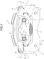
Fig. 1] Fig. 1 is a front view of a disc brake apparatus according to an embodiment of the invention showing a front configuration thereof. - [
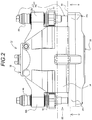
Fig. 2] Fig. 2 is a plan view of the disc brake apparatus shown inFig. 1 showing a top configuration thereof. - [
Fig. 3] Fig. 3 is a right side view of the disc brake apparatus shown inFig. 1 showing a right side configuration thereof. - [
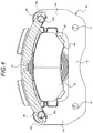
Fig. 4] Fig. 4 is a sectional view of the disc brake apparatus according to the embodiment of the invention taken along a line B-B shown inFig. 2 . - [
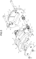
Fig. 5] Fig. 5 is an exploded perspective view of the disc brake apparatus shown inFig. 1 . - [
Fig. 6] Fig. 6 is a sectional view of the disc brake apparatus according to the embodiment taken along a line A-A shown inFig. 1 , - [
Fig. 7] Fig. 7 is a sectional view corresponding to the sectional view taken along the line A-A shown inFig. 1 , which shows a first modified example of the disc brake apparatus according to the embodiment of the invention - [
Fig. 8] Fig. 8 is a sectional view corresponding to the sectional view taken along the line A-A shown inFig. 1 , which shows a second modified example of the disc brake apparatus according to the embodiment of the invention. - Hereinafter, a disc brake apparatus according to an embodiment of the invention will be described in detail by reference to the drawings.
- According to a basic configuration of a
disc brake apparatus 10 of this embodiment, thedisc brake apparatus 10 has asupport member 12,slide members 22 which are supported by thissupport member 12, and acaliper 30 which is supported via theslide members 22. - The
support member 12 is fixed to a vehicle body and plays a role of supporting thecaliper 30 slidably. In this embodiment, thesupport member 12 is disposed between a cylinder portion 32 (an inboard body) and a claw portion 36 (an outboard body) of the caliper 30 (in other words, within a frame of the caliper 30). - The
support member 12 includes, at least,anchors bridge 16, mountingholes 18 and slide member mounting portions 20 (refer toFig. 5 ). Theanchors support member 12, respectively, where arotor 60 enters and exits when it rotates. In this embodiment, theanchors inner pad 46 and function as torque bearing portions which bear force which attempts to rotate theinner pad 46 together with therotor 60 when the brakes are applied. Theinner pad 46 is made up of apressure plate 48 which is made of a sheet of steel and alining 50 which is a frictional member. Theinner pad 46 is supported on thesupport member 12 via part of thepressure plate 48. - The
bridge 16 is a connecting member which connects together theanchor 14a which is disposed on the rotating rotor entrance side and theanchor 14b which is disposed on the rotating rotor exit side of thesupport member 12 where therotor 60 enters and exits when it rotates. Themounting holes 18 are holes which are provided in connecting portions between theanchors bridge 16 for passage of bolts (not shown) which are screwed into mounting holes (not shown) provided on the vehicle body to thereby fasten thesupport member 12 to the vehicle body. - The slide
member mounting portions 20 are through holes which are provided at distal ends of the pair ofanchors rotor 60 when therotor 60 is assembled to thedisc brake apparatus 10. Theslide members 22 are mounted in the corresponding slidemember mounting portions 20, and torque caused in anouter pad 52, which will be described in detail later, is transmitted to theslide members 22. - The
slide members 22 according to this embodiment are each made up of aguide pin 24 which makes up an inner slide portion which is situated on an inner side of thesupport member 12 and ananchor pin 26 which makes up an outer slide portion which is situated on an outer side of thesupport member 12. In this embodiment, a sleeve 28 (refer toFig. 5 ), which makes up the inner slide portion, is disposed on an outer circumference of theguide pin 24. In addition, thecaliper 30, which will be described in detail later, is configured so as to slide along an outer circumference of thesleeve 28. Theanchor pin 26 includes asmall diameter portion 26a and alarge diameter portion 26b which are disposed in the order from a proximal end portion to a distal end portion of theanchor pin 26. Thelarge diameter portion 26b functions as the outer slide portion. As a result of theanchor pin 26 including thelarge diameter portion 26b and theouter diameter portion 26b configured to function as the outer slide portion, even in the event that theouter pad 52, which will be described in detail later, wears, a distance from a contact portion (including a contact length and a contact position) with anouter transmission surface 36d to thesupport member 12 can be maintained constant. This can stabilize the application of braking torque applied when the brakes are applied. - In this embodiment, the
guide pin 24 and theanchor pin 26 are separate members. Then, a proximal end side internally threadedportion 26c of theanchor pin 26 is screwed on a proximal end side externally threadedportion 24a of theguide pin 24 which is inserted through the slidemember mounting portion 20 provided in thesupport member 12, whereby theguide pin 24 and theanchor pin 26 are fixed to thesupport member 12 with thesupport member 12 held therebetween. By adopting this configuration, even when thesupport member 12 is formed thin, it is possible to ensure a sufficient assembling margin between theguide pin 24 and theanchor pin 26. - The
caliper 30 according to this embodiment has thecylinder portion 32, theclaw portion 36 and a back body portion 34 (a bridge) Thecylinder portion 32 constitutes a drive source for thedisc brake apparatus 10 according to this embodiment and apiston 38 and acylinder 32a which accommodates thepiston 38 and from which thepiston 38 is caused to project. In addition,support portions 32b are provided on thecylinder portion 32, and thesupport portions 32b have through holes through which the guide pins 24 are inserted. The through holes in thesupport portions 32b are provided so as to be situated further radially outwards than the outer circumference of therotor 60 with thecaliper 30 assembled to thedisc brake apparatus 10. The reason that the through holes are so formed is that the guide pins 24 which are inserted therethrough are situated further radially outwards than the outer circumference of therotor 60 so as to avoid the interference of the guide pins 24 with therotor 60, - An
inner transmission surface 32c is provided on an inner circumferential surface of the through hole of eachsupport portion 32b so as to transmit braking torque to the sleeve 28 (theguide pin 24 via the sleeve 28).Boots support portion 32 which slides over thesleeve 28 so as to be aligned along a sliding direction, and an outer circumference (that is, a sliding surface) of thesleeve 28 are covered by theseboots inner transmission surface 32c has a bore diameter which is determined so that theinner transmission surface 32 loosely fits on the outer circumference of thesleeve 28. Then, gaps A1, A2 are defined between thesleeve 28 and theinner transmission surface 32c due to thicknesses ofboot fixing portions sleeve 28 is located from thesupport portion 32b. - The
claw portion 36 bears reaction force generated as a result of pressing force generated by thepiston 38. Acutout portion 36a is provided in theclaw portion 36 in a position which corresponds to a position on thecylinder portion 32 where thecylinder 32a is formed. This is because an inner circumference of thecylinder 32a of thecylinder portion 32 is worked by making use of thecutout portion 36a. Blocks (two blocks in this embodiment) which make up theclaw portion 36 each have a throughhole 36b through which abolt 44 is inserted. The throughhole 36b is desirably formed as a stepped hole which keeps a bolt head of thebolt 44 used for fastening from projecting to an exterior portion. Thecaliper 30 is disposed in a limited space defined between therotor 60 and an inner wall of a wheel. Due to this, the interference of thecaliper 30 with the wheel can be suppressed by reducing the number of projecting portions from thecaliper 30, and the formation of a flat surface on thecaliper 30 leads to an improvement in aesthetic appearance thereof. - The
outer pad 52 is fastened to an inner side of theclaw portion 36. Similar to theinner pad 46, theouter pad 52 is made up of apressure plate 54 of a sheet of steel and a lining 56 which is formed of frictional material. Due to this, by fastening theouter pad 52 to theclaw portion 36, not only can the rigidity of theclaw portion 36 be enhanced, but also theclaw portion 36 and theouter pad 52 can be treated as an integral part. - By fastening the
outer pad 52 to theclaw portion 36, the tangential force of theouter pad 52 is transmitted to theclaw portion 36. Due to this, braking torque generated by the frictional force of theouter pad 52 is then transmitted to the anchor pins 26 and the guide pins 24 via thecaliper 30. -
Rear enclosing portions 36c for enclosing the distal end portions (thelarge diameter portions 26b) of the anchor pins 26 are provided in positions of theclaw portion 36 which correspond to the support portions The enclosingportions 36c make up theouter transmission surfaces 36d which transmit braking torque generated by the frictional force of theouter pad 52 when the brakes are applied to the anchor pins 26. The enclosingportions 36c are each formed so as to cover an outer circumference of theanchor pin 26 over a range of 180 degrees or wider including a braking torque transmission point to theanchor pin 26. By enclosing the outer circumference of theanchor pin 26 over the range of 180 degrees or greater, a good holding performance of thecaliper 30 can be maintained, while reducing the thickness of the portion which makes up the enclosingportion 36c. In order to mitigate the assembling and working accuracy at which the pair of anchor pins 26 are disposed, slight gaps B1, B2 are provided between the anchor pins 26 and the correspondingrear enclosing portions 36c when the brakes are not applied. - The enclosing
portions 36c are provided so that theouter transmission surfaces 36d are situated further inboards (that is, closer to the rotor 60) than thepressure plate 54 of theouter pad 52. By adopting this configuration, when the braking torque is transmitted to the anchor pins 26, the braking torque is so transmitted more in the position situated inboards of thepressure plate 54 than transmitted directly from thepressure plate 54. Due to this, a distance from thesupport member 12 to the torque transmission point becomes short, whereby a load applied to the anchor pins 26 is reduced. Consequently, it is possible to suppress the deformation of the anchor pins 26 and the deflection of thesupport member 12. - The
back body portion 34 is an element which straddles therotor 60 in a position lying further radially outwards than the outer circumference thereof to connect thecylinder portion 32 and theclaw portion 36. - In the
disc brake apparatus 10 configured in the way described above, thecaliper 30 is supported on thesleeves 28 which are disposed on the outer circumferences of the guide pins 24 via theboots caliper 30 where therotor 60 enters when it rotates are smaller than the gaps (the gap A2, the gap B2) situated closer to a rotating rotor exit side of thecaliper 30 where therotor 60 enters and exits when it rotates. Due to this, the relationship in terms of size of the gap A1 to the gap B2 can be described as B1<B2<A1<A2. - In the
disc brake apparatus 10 configured in the way described above, thecaliper 30 is supported via theboots caliper 30 bears the tangential force of theouter pad 52 and is then caused to slide in a rotational direction (R) of therotor 60 to thereby be brought into contact with theslide members 22. Here, when the sizes of the gaps A1 to B2 are caused to differ, the number of transmission surfaces which come into contact with theslide members 22 changes in accordance to the magnitude of the braking torque. - Specifically, the number of transmission surfaces will change as follows. Firstly, in an initial stage of braking, the
outer transmission surface 36d which is situated on the rotating rotor entrance side where therotor 60 enters when it rotates is brought into contact with the anchor pin 26 (whereby the gap B1 is eliminated). When the braking torque is applied further, theouter transmission surface 36d which is situated on the rotating rotor exit side where therotor 60 exits when it rotates is brought into contact with the anchor pin 26 (whereby the gap B2 is eliminated). - Then, when the braking toque applied becomes greater, the
inner transmission surface 32c which is situated on the rotating rotor entrance side is brought into contact with the guide pin 24 (the sleeve 28) (whereby the gap A1 is eliminated). When the braking torque applied becomes far greater, theinner transmission surface 32c on the rotating rotor exist side is brought into contact with the guide pin 24 (the sleeve 28) (whereby the gap A2 is eliminated).Thus, all the four transmission surfaces are brought into function. - In the
disc brake apparatus 10 of this embodiment, the anchor pins 26 which make up the outer slide portions and the guide pins 24 which make up the inner slide portions are disposed on the outer side and the inner side of thesupport member 12, respectively. Namely, the braking torque is designed to be inputted in a dispersed fashion in accordance to the magnitude of the tangential force applied to theouter pad 52. Due to this, even in the event that great tangential force is applied to theouter pad 52, there are no fears that the anchor pins 26 are deformed. - Since the configuration is adopted in which the braking force is dispersed to the anchor pins 26 which are provided on the outer side of the
support member 12 and the guide pins 24 which are provided on the inner side of thesupport member 12, torsional force indicated by an arrow (A) inFig. 6 is mitigated, thereby making it possible to suppress the distortion of thesupport member 12. - Consequently, it is possible to prevent the occurrence of a tilting phenomenon of the
caliper 30 attributed to the deformation of the anchor pins 26 and thesupport member 12. Thus, it is also possible to suppress the occurrence of eccentric wear of the pads (theinner pad 46 and the outer pad 52) which would otherwise be caused by the tilting phenomenon of thecaliper 30. - In the figures, as a preferred mode for carrying out the invention, one of the specific modes is illustrated. However, provided that the working effects described above can be obtained, there is imposed no limitation to the external appearances or forms and materials of the
support member 12 and thecaliper 30. - In the embodiment, the relationship in terms of size of the gaps A1 to B2 is described as B1<B2<A1<A2. However, the relationship can be set differently depending upon whether the anchoring of the tangential force or the braking torque when the brakes are applied is triggered by the push anchor or the pull anchor. For example, even through the relationship in terms of size of the gaps is set as B2<B1 <A2<A1, the setting can be regarded as constituting part of the invention.
- In the
disc brake apparatus 10 according to this embodiment, when the brakes are applied, thecaliper 30 slides in the rotational direction (R) of therotor 60. Due to this, in the event that the magnitude of the gaps A (A1, A2) is made equal to the magnitude of the gaps B (B1, B2), the inner transmission surfaces 32c and theouter transmission surfaces 36d are brought into contact with the guide pins 24 and the anchor pins 26 at the same time. Even in the event that this configuration is adopted, the configuration can be regarded as constituting part of the invention. - In the embodiment, the
outer pad 52 is described as being fixed to theclaw portion 36 with thebolts 44. However, other fastening means than the means using thebolts 44 may be adopted including a fitting making use of irregularities, as long as a configuration adopted can transmit the tangential force applied to theouter pad 52 to theclaw portion 36. - Next, referring to
Fig. 7 , a first modified example made to the disc brake apparatus according to the invention will be described,Fig. 7 is a sectional view showing a configuration corresponding to the configuration of the embodiment shown inFig. 6 . In the embodiment described above, the sleeves 28 (refer toFig. 6 ) are provided on the outer circumferences of the guide pins 24 which make up the inner slide portions. In contrast with this, the following configuration is adopted in this modified example. Thesleeves 28 are deleted, and guidepins 24 having a larger diameter are used instead. Then,support portions 32b slide over outer circumferences of the guide pins 24, and inner transmission surfaces 32c are brought into contact with the outer circumferences of the guide pins 24. - Even in the event that the inner slide portions are configured in the way described above, similar advantageous effects to those of the embodiment can be obtained. In addition, since the
sleeves 28 can be deleted, the number of parts needed to be assembled and the number of assembling steps can be reduced accordingly. - Next, referring to
Fig. 8 , a second modified example will be described. In the modified example shown inFig. 8 , an inner slide portion and an outer slide portion are formed into anintegral slide member 22. - In the case of this modified example, the
slide member 22 is screwed into asupport member 12 for assemblage to thesupport member 12. Due to this, an internal thread is formed on a slidemember mounting portion 20 of thesupport member 12. In addition, an externally threadedportion 22c is provided on theslide member 22 between a guidepin constituting portion 22a which constitutes the inner slide portion and an anchorpin constituting portion 22b which constitutes the outer slide portion. - In the
slide member 22 configured as described above, a proximal end face of the guidepin constituting portion 22a constitutes a reference point for use in determining the length of ananchor pin 26. Due to this, a proximal end portion of the guidepin constituting portion 22a is formed greater in diameter than an internally threaded hole in the slidemember mounting portion 20, and the proximal end face thereof is configured to be brought into abutment with a planar plane of thesupport member 12. - Even in the event that the
slide member 22 is formed in this way, a similar advantageous effects to those of the embodiment can be obtained. In addition, since the guidepin constituting portion 22a and the anchorpin constituting portion 22b are formed integral, the number of parts needed to be assembled and the number of assembling steps can be reduced. - Here, the characteristics of the embodiment of the disc brake apparatus according to the invention will be briefly summarized by item by item below.
- [1] A disc brake apparatus having:
- a support member;
- a slide member disposed along an axial direction of a rotor and having an inner slide portion on an inner side of the support member and an outer slide portion on an outer side of the support member; and
- a caliper which is held so that tangential force of an outer pad is transmitted to a claw portion and which is supported on the slide member,
- wherein the caliper includes:
- an outer transmission surface which transmits braking torque generated in the outer pad to the outer slide portion; and
- an inner transmission surface which transmits the braking torque to the inner slide portion.
- [2] The disc brake apparatus configured as described under [1] above, wherein
the slide member is made up of the inner slide portion and the outer slide portion which are separate members, and wherein
the constituent member of the inner slide portion and the constituent member of the outer slide portion are fastened together with the support member held therebetween. - [3] The disc brake apparatus configured as described under [1] or [2] above, wherein
the outer slide portion is made up, of the large diameter portion and the small diameter portion which are provided along the axial direction of the slide member, of the large diameter portion. - [4] The disc brake apparatus configured as described under any one of [1] to [3] above, wherein
the caliper is allowed to slide in the axial direction of the rotor via the inner slide portion, and wherein
the inner slide portion has the sleeve which is interposed between the sliding portion of the caliper and the inner slide portion. - [5] The disc brake apparatus configured as described under any one of [1] to [4] above, wherein
the first gap is provided between the outer slide portion and the outer transmission surface, wherein
the second gap is provided between the inner slide portion and the inner transmission surface, and wherein
the second gap is set to be wider than the first gap. - [6] The disc brake apparatus configured as described under any one of [1] to [5] above, wherein
the first gap is provided between the outer slide portion and the outer transmission surface, wherein
the second gap is provided between the inner slide portion and the inner transmission surface, and wherein
in each of the first gap and the second gap, the gap situated on the exit side of the caliper where the rotor exits when it rotates is set to be wider than the gap situated on the entrance side where the rotor enters when it rotates. - [7] The disc brake apparatus configured as described under any one of [1] to [6] above, wherein
the outer transmission surface is the enclosing portion which encloses the outer circumference of the outer slide portion, and wherein
the enclosing portion encloses the outer circumference of the outer slide portion over the range of 180 degrees or greater including the braking torque transmission point to the outer slide portion. - [8] The disc brake apparatus configured as described under any one of [1] to [7] above, wherein the outer pad is fastened to the claw portion.
- The disc brake apparatus of the invention is not limited to the embodiment described heretofore and hence can be modified or improved as required. In addition, the materials, shapes, dimensions, numbers, arranging positions and the like of the constituent elements of the embodiment are arbitrary and are not limited thereto, provided that the invention can be attained by those constituent elements.
- This patent application is based on Japanese Patent Application (No.
2014-233810) filed on November 18, 2014 - According to the disc brake apparatus of the invention, even in the event that the configuration of the support member is simplified and that the torque bearing construction is adopted in which the braking torque is borne by the pins, it is possible to prevent the deformation of the pins and the support member. Thus, it is also possible to suppress the occurrence of eccentric wear that would otherwise be caused by the deformed pins or support member.
- 10: disc brake apparatus; 12: support member; 14a: anchor; 14b: anchor; 16: bridge; 18: mounting hole; 20: slide portion mounting portion; 22: slide member; 22a: guide pin constituting portion; 22b: anchor pin constituting portion; 22c: externally threaded portion; 24: guide pin; 24a: proximal end side externally threaded portion; 26: anchor pin; 26a: small diameter portion; 26b: large diameter portion; 28: sleeve; 30: caliper; 32: cylinder portion; 32a: cylinder; 32b: support portion; 32c: inner transmission surface; 34: back body portion; 36: claw portion; 36a: cutout portion; 36b: through hole; 36c: rear enclosing portion; 36d: outer transmission surface; 38: piston; 40: boot; 40a: boot fixing portion; 42: boot; 42a: boot fixing portion; 44: bolt; 46: inner pad; 48: pressure plate; 50: lining; 52: outer pad; 54: pressure plate; 56: lining; 60: rotor.
Claims (8)
- A disc brake apparatus comprising:a support member;a slide member disposed along an axial direction of a rotor and having an inner slide portion on an inner side of the support member and an outer slide portion on an outer side of the support member; anda caliper which is held so that tangential force of an outer pad is transmitted to a claw portion and which is supported on the slide member,wherein the caliper includes:an outer transmission surface which transmits braking torque generated in the outer pad to the outer slide portion; andan inner transmission surface which transmits the braking torque to the inner slide portion.
- The disc brake apparatus according to Claim 1, wherein, in the slide member, the inner slide portion and the outer slide portion are structured as separate members, and
wherein a constituent member of the inner slide portion and a constituent member of the outer slide portion are fastened together with the support member held therebetween. - The disc brake apparatus according to Claim 1 or 2, wherein the outer slide portion is made up of a large diameter portion of the large diameter portion and a small diameter portion which are provided along an axial direction of the slide member.
- The disc brake apparatus according to any one of Claims 1 to 3, wherein the caliper is slidable in the axial direction of the rotor via the inner slide portion, and
wherein a sleeve which is interposed between a sliding portion of the caliper and the inner slide portion. - The disc brake apparatus according to any one of Claims 1 to 4, wherein a first gap is provided between the outer slide portion and the outer transmission surface,
wherein a second gap is provided between the inner slide portion and the inner transmission surface, and
wherein the second gap is set to be larger than the first gap. - The disc brake apparatus according to any one of Claims 1 to 5, wherein a first gap is provided between the outer slide portion and the outer transmission surface,
wherein a second gap is provided between the inner slide portion and the inner transmission surface, and
wherein, in each of the first gap and the second gap, a gap on an exit side of the caliper where the rotor exits when the rotor rotates is set to be larger than a gap on an entrance side where the rotor enters when the rotor rotates. - The disc brake apparatus according to any one of Claims 1 to 6, wherein the outer transmission surface is an enclosing portion which encloses an outer circumference of the outer slide portion, and
wherein the enclosing portion encloses the outer circumference of the outer slide portion over a range of 180 degrees or greater including a braking torque transmission point to the outer slide portion. - The disc brake apparatus according to any one of Claims 1 to 7, wherein the outer pad is fastened to the claw portion.
Applications Claiming Priority (2)
| Application Number | Priority Date | Filing Date | Title |
|---|---|---|---|
| JP2014233810A JP2016098848A (en) | 2014-11-18 | 2014-11-18 | Disc brake device |
| PCT/JP2015/082426 WO2016080451A1 (en) | 2014-11-18 | 2015-11-18 | Disc brake device |
Publications (2)
| Publication Number | Publication Date |
|---|---|
| EP3222871A1 true EP3222871A1 (en) | 2017-09-27 |
| EP3222871A4 EP3222871A4 (en) | 2018-06-27 |
Family
ID=56013985
Family Applications (1)
| Application Number | Title | Priority Date | Filing Date |
|---|---|---|---|
| EP15861620.1A Withdrawn EP3222871A4 (en) | 2014-11-18 | 2015-11-18 | Disc brake device |
Country Status (5)
| Country | Link |
|---|---|
| US (1) | US20170350461A1 (en) |
| EP (1) | EP3222871A4 (en) |
| JP (1) | JP2016098848A (en) |
| CN (1) | CN107002787A (en) |
| WO (1) | WO2016080451A1 (en) |
Cited By (1)
| Publication number | Priority date | Publication date | Assignee | Title |
|---|---|---|---|---|
| US11607922B2 (en) | 2018-02-14 | 2023-03-21 | Hendrickson Commercial Vehicle Systems GmbH | Spring for use in conjunction with a vehicle |
Families Citing this family (6)
| Publication number | Priority date | Publication date | Assignee | Title |
|---|---|---|---|---|
| GB2560763B (en) * | 2017-03-24 | 2021-10-27 | Liberty Vehicle Tech Limited | Brake calipers |
| JP7043353B2 (en) * | 2018-06-14 | 2022-03-29 | 曙ブレーキ工業株式会社 | Opposed piston type disc brake device |
| CN110388395A (en) * | 2019-06-13 | 2019-10-29 | 东风柳州汽车有限公司 | Automobile floating formula clamp pin shaft |
| CN111015739A (en) * | 2019-12-30 | 2020-04-17 | 六壹八技术(深圳)有限公司 | Brake mechanism and robot |
| DE102020114659A1 (en) * | 2020-06-02 | 2021-12-02 | Mann+Hummel Gmbh | Brake caliper device, disc brake assembly, use of a brake caliper device and method for radial retention of air |
| EP4652382A1 (en) * | 2023-01-18 | 2025-11-26 | Hendrickson USA, L.L.C. | Shear-to-torque guide pin assembly for heavy-duty vehicles |
Family Cites Families (11)
| Publication number | Priority date | Publication date | Assignee | Title |
|---|---|---|---|---|
| JPS52106781U (en) * | 1976-02-12 | 1977-08-13 | ||
| US4193481A (en) * | 1978-07-25 | 1980-03-18 | General Motors Corporation | Drag free sliding caliper disc brake bushing |
| DE2845936A1 (en) * | 1978-10-21 | 1980-04-30 | Teves Gmbh Alfred | BRAKE POWER TRANSFER BOLT GUIDE FOR A FLOATING CALIPER DISC BRAKE |
| JPS5639876A (en) * | 1979-09-07 | 1981-04-15 | Sumitomo Electric Industries | Method of exchanging pad of disc brake |
| DE4126339C2 (en) * | 1991-08-09 | 2002-04-04 | Continental Teves Ag & Co Ohg | Part floating disc brake for high-performance vehicles |
| JPH10110753A (en) * | 1996-10-01 | 1998-04-28 | Akebono Brake Ind Co Ltd | Disc brake device |
| JP2006057718A (en) * | 2004-08-19 | 2006-03-02 | Akebono Brake Ind Co Ltd | Floating calliper type disk brake |
| JP5087645B2 (en) * | 2010-03-11 | 2012-12-05 | アケボノ コーポレイション(ノース アメリカ) | Disc brake with pin rail caliper |
| JP2012072842A (en) * | 2010-09-29 | 2012-04-12 | Akebono Brake Ind Co Ltd | Floating type disc brake |
| JP2012172739A (en) * | 2011-02-18 | 2012-09-10 | Akebono Brake Ind Co Ltd | Brake pad for disc brake device |
| US8991566B2 (en) * | 2011-06-27 | 2015-03-31 | Ausco Products, Inc. | Caliper brake |
-
2014
- 2014-11-18 JP JP2014233810A patent/JP2016098848A/en active Pending
-
2015
- 2015-11-18 EP EP15861620.1A patent/EP3222871A4/en not_active Withdrawn
- 2015-11-18 CN CN201580062365.XA patent/CN107002787A/en active Pending
- 2015-11-18 WO PCT/JP2015/082426 patent/WO2016080451A1/en not_active Ceased
- 2015-11-18 US US15/525,312 patent/US20170350461A1/en not_active Abandoned
Cited By (1)
| Publication number | Priority date | Publication date | Assignee | Title |
|---|---|---|---|---|
| US11607922B2 (en) | 2018-02-14 | 2023-03-21 | Hendrickson Commercial Vehicle Systems GmbH | Spring for use in conjunction with a vehicle |
Also Published As
| Publication number | Publication date |
|---|---|
| US20170350461A1 (en) | 2017-12-07 |
| JP2016098848A (en) | 2016-05-30 |
| CN107002787A (en) | 2017-08-01 |
| EP3222871A4 (en) | 2018-06-27 |
| WO2016080451A1 (en) | 2016-05-26 |
Similar Documents
| Publication | Publication Date | Title |
|---|---|---|
| US20170350461A1 (en) | Disc brake device | |
| CN103047325B (en) | Mechanical arresting disk brake | |
| US10156274B2 (en) | Caliper for disc brake | |
| US5464077A (en) | Floating-caliper spot-type disc brake for high-powered vehicles | |
| EP3559495B1 (en) | Spring device for disc brake, pad spring and disc brake assembly | |
| US9568059B2 (en) | Disc brake | |
| US10718393B2 (en) | Spring of a caliper of a disc brake | |
| US10724589B2 (en) | Brake pad retention system of a disc brake of a motor vehicle | |
| WO2014065400A1 (en) | Disk brake device and brake pad for disk brake device | |
| JP4741693B2 (en) | Decorative plate mounting structure | |
| EP3809009B1 (en) | Vehicular disc brake | |
| JP2006057718A (en) | Floating calliper type disk brake | |
| EP3121477A1 (en) | A disc brake assembly | |
| EP3321535B1 (en) | Disc brake device | |
| EP3680504B1 (en) | Vehicular disc brake | |
| JP2014190478A (en) | Disc brake device | |
| JP6202434B2 (en) | Disc brake device | |
| WO2017200012A1 (en) | Disc brake device | |
| WO2017130628A1 (en) | Disc brake device and brake pad for disc brake device | |
| WO2012077754A1 (en) | Disc brake | |
| JP5544263B2 (en) | Brake pads | |
| US20070068747A1 (en) | Self-energizing sliding caliper | |
| WO2019189506A1 (en) | Floating-type disk brake | |
| TWI703281B (en) | Disc brake | |
| JP5603797B2 (en) | Vehicle disc brake |
Legal Events
| Date | Code | Title | Description |
|---|---|---|---|
| PUAI | Public reference made under article 153(3) epc to a published international application that has entered the european phase |
Free format text: ORIGINAL CODE: 0009012 |
|
| 17P | Request for examination filed |
Effective date: 20170515 |
|
| AK | Designated contracting states |
Kind code of ref document: A1 Designated state(s): AL AT BE BG CH CY CZ DE DK EE ES FI FR GB GR HR HU IE IS IT LI LT LU LV MC MK MT NL NO PL PT RO RS SE SI SK SM TR |
|
| AX | Request for extension of the european patent |
Extension state: BA ME |
|
| DAV | Request for validation of the european patent (deleted) | ||
| DAX | Request for extension of the european patent (deleted) | ||
| A4 | Supplementary search report drawn up and despatched |
Effective date: 20180529 |
|
| RIC1 | Information provided on ipc code assigned before grant |
Ipc: F16D 55/2265 20060101AFI20180523BHEP |
|
| STAA | Information on the status of an ep patent application or granted ep patent |
Free format text: STATUS: THE APPLICATION HAS BEEN WITHDRAWN |
|
| 18W | Application withdrawn |
Effective date: 20180629 |