EP3222854B1 - Axi-zentrifugalverdichter - Google Patents
Axi-zentrifugalverdichter Download PDFInfo
- Publication number
- EP3222854B1 EP3222854B1 EP17156153.3A EP17156153A EP3222854B1 EP 3222854 B1 EP3222854 B1 EP 3222854B1 EP 17156153 A EP17156153 A EP 17156153A EP 3222854 B1 EP3222854 B1 EP 3222854B1
- Authority
- EP
- European Patent Office
- Prior art keywords
- compressor
- axial
- section
- inlet
- flow path
- Prior art date
- Legal status (The legal status is an assumption and is not a legal conclusion. Google has not performed a legal analysis and makes no representation as to the accuracy of the status listed.)
- Active
Links
Images

Classifications
-
- F—MECHANICAL ENGINEERING; LIGHTING; HEATING; WEAPONS; BLASTING
- F02—COMBUSTION ENGINES; HOT-GAS OR COMBUSTION-PRODUCT ENGINE PLANTS
- F02C—GAS-TURBINE PLANTS; AIR INTAKES FOR JET-PROPULSION PLANTS; CONTROLLING FUEL SUPPLY IN AIR-BREATHING JET-PROPULSION PLANTS
- F02C3/00—Gas-turbine plants characterised by the use of combustion products as the working fluid
- F02C3/04—Gas-turbine plants characterised by the use of combustion products as the working fluid having a turbine driving a compressor
- F02C3/08—Gas-turbine plants characterised by the use of combustion products as the working fluid having a turbine driving a compressor the compressor comprising at least one radial stage
-
- F—MECHANICAL ENGINEERING; LIGHTING; HEATING; WEAPONS; BLASTING
- F04—POSITIVE - DISPLACEMENT MACHINES FOR LIQUIDS; PUMPS FOR LIQUIDS OR ELASTIC FLUIDS
- F04D—NON-POSITIVE-DISPLACEMENT PUMPS
- F04D19/00—Axial-flow pumps
- F04D19/02—Multi-stage pumps
- F04D19/028—Layout of fluid flow through the stages
-
- F—MECHANICAL ENGINEERING; LIGHTING; HEATING; WEAPONS; BLASTING
- F04—POSITIVE - DISPLACEMENT MACHINES FOR LIQUIDS; PUMPS FOR LIQUIDS OR ELASTIC FLUIDS
- F04D—NON-POSITIVE-DISPLACEMENT PUMPS
- F04D17/00—Radial-flow pumps, e.g. centrifugal pumps; Helico-centrifugal pumps
- F04D17/02—Radial-flow pumps, e.g. centrifugal pumps; Helico-centrifugal pumps having non-centrifugal stages, e.g. centripetal
- F04D17/025—Radial-flow pumps, e.g. centrifugal pumps; Helico-centrifugal pumps having non-centrifugal stages, e.g. centripetal comprising axial flow and radial flow stages
-
- F—MECHANICAL ENGINEERING; LIGHTING; HEATING; WEAPONS; BLASTING
- F04—POSITIVE - DISPLACEMENT MACHINES FOR LIQUIDS; PUMPS FOR LIQUIDS OR ELASTIC FLUIDS
- F04D—NON-POSITIVE-DISPLACEMENT PUMPS
- F04D19/00—Axial-flow pumps
- F04D19/02—Multi-stage pumps
-
- F—MECHANICAL ENGINEERING; LIGHTING; HEATING; WEAPONS; BLASTING
- F04—POSITIVE - DISPLACEMENT MACHINES FOR LIQUIDS; PUMPS FOR LIQUIDS OR ELASTIC FLUIDS
- F04D—NON-POSITIVE-DISPLACEMENT PUMPS
- F04D29/00—Details, component parts, or accessories
- F04D29/26—Rotors specially for elastic fluids
- F04D29/28—Rotors specially for elastic fluids for centrifugal or helico-centrifugal pumps for radial-flow or helico-centrifugal pumps
- F04D29/284—Rotors specially for elastic fluids for centrifugal or helico-centrifugal pumps for radial-flow or helico-centrifugal pumps for compressors
- F04D29/286—Rotors specially for elastic fluids for centrifugal or helico-centrifugal pumps for radial-flow or helico-centrifugal pumps for compressors multi-stage rotors
-
- F—MECHANICAL ENGINEERING; LIGHTING; HEATING; WEAPONS; BLASTING
- F04—POSITIVE - DISPLACEMENT MACHINES FOR LIQUIDS; PUMPS FOR LIQUIDS OR ELASTIC FLUIDS
- F04D—NON-POSITIVE-DISPLACEMENT PUMPS
- F04D29/00—Details, component parts, or accessories
- F04D29/26—Rotors specially for elastic fluids
- F04D29/32—Rotors specially for elastic fluids for axial flow pumps
- F04D29/321—Rotors specially for elastic fluids for axial flow pumps for axial flow compressors
-
- F—MECHANICAL ENGINEERING; LIGHTING; HEATING; WEAPONS; BLASTING
- F04—POSITIVE - DISPLACEMENT MACHINES FOR LIQUIDS; PUMPS FOR LIQUIDS OR ELASTIC FLUIDS
- F04D—NON-POSITIVE-DISPLACEMENT PUMPS
- F04D29/00—Details, component parts, or accessories
- F04D29/40—Casings; Connections of working fluid
- F04D29/52—Casings; Connections of working fluid for axial pumps
- F04D29/54—Fluid-guiding means, e.g. diffusers
- F04D29/541—Specially adapted for elastic fluid pumps
- F04D29/542—Bladed diffusers
-
- F—MECHANICAL ENGINEERING; LIGHTING; HEATING; WEAPONS; BLASTING
- F05—INDEXING SCHEMES RELATING TO ENGINES OR PUMPS IN VARIOUS SUBCLASSES OF CLASSES F01-F04
- F05D—INDEXING SCHEME FOR ASPECTS RELATING TO NON-POSITIVE-DISPLACEMENT MACHINES OR ENGINES, GAS-TURBINES OR JET-PROPULSION PLANTS
- F05D2220/00—Application
- F05D2220/30—Application in turbines
- F05D2220/32—Application in turbines in gas turbines
-
- F—MECHANICAL ENGINEERING; LIGHTING; HEATING; WEAPONS; BLASTING
- F05—INDEXING SCHEMES RELATING TO ENGINES OR PUMPS IN VARIOUS SUBCLASSES OF CLASSES F01-F04
- F05D—INDEXING SCHEME FOR ASPECTS RELATING TO NON-POSITIVE-DISPLACEMENT MACHINES OR ENGINES, GAS-TURBINES OR JET-PROPULSION PLANTS
- F05D2220/00—Application
- F05D2220/30—Application in turbines
- F05D2220/32—Application in turbines in gas turbines
- F05D2220/321—Application in turbines in gas turbines for a special turbine stage
- F05D2220/3216—Application in turbines in gas turbines for a special turbine stage for a special compressor stage
-
- F—MECHANICAL ENGINEERING; LIGHTING; HEATING; WEAPONS; BLASTING
- F05—INDEXING SCHEMES RELATING TO ENGINES OR PUMPS IN VARIOUS SUBCLASSES OF CLASSES F01-F04
- F05D—INDEXING SCHEME FOR ASPECTS RELATING TO NON-POSITIVE-DISPLACEMENT MACHINES OR ENGINES, GAS-TURBINES OR JET-PROPULSION PLANTS
- F05D2240/00—Components
- F05D2240/35—Combustors or associated equipment
Definitions
- the present disclosure generally relates to a gas turbine propulsion system, and more particularly relates to an axi-centrifugal compressor in which a proportioned distribution of the pressure rise across the axial and centrifugal compressor sections is achieved.
- Gas turbine propulsion systems for aircraft must deliver high performance in a compact, lightweight configuration. This is particularly important in smaller jet propulsion systems typically used in regional and business aviation applications as well as in other turbofan, turboshaft, turboprop and rotorcraft applications.
- a well-known way to improve engine efficiency is to increase the overall pressure rise of the compressor. However, this is typically done by increasing the number of compressor stages, which increases the volume, weight, and cost of the engine; all of which reduce the value and competitive position of the engine.
- Larger commercial transport engines typically utilize "all-axial" high pressure compressors. Relative to the larger commercial transport engines, these relatively-smaller propulsion engines more frequently utilize "axi-centrifugal" compressors.
- Compressors of this type typically include one or more axial compressor stages followed by a centrifugal stage.
- the centrifugal compressor provides a second mechanism to increase overall pressure rise but often results in an increase of the diameter of the impeller in the centrifugal stage, resulting in increased weight and engine size.
- axial and centrifugal compressors have different optimal operating regimes, different physical characteristics, and different sensitivities to geometric and/or operational variation.
- conventional gas turbine propulsion systems pursue a very high level of aerodynamic loading in the centrifugal compressor section, relative to the axial compressor section, in an attempt to benefit from the centrifugal stabilizing effect and performance robustness.
- this may require a relatively large and heavy centrifugal compressor section to achieve the overall pressure rise across the compressor.
- the present disclosure provides an axi-centrifugal compressor configuration having a proportioned pressure ratio distribution across the compressor.
- a relatively high level of pressure rise is provided on the axial portion of the compressor, which leads to a reduction in the diameter and weight of the centrifugal stage compared to conventional compressor designs.
- a high level of pressure rise is also provided on each individual axial stage to minimize the stage count, which leads to a shorter length, lighter weight, lower cost, and high performance compared to conventional compressor designs. Aerodynamic over-loading of the axial stages that would otherwise result in boundary layer separations, low efficiency, and poor compressor operability is minimized.
- An axi-centrifugal compressor is provided in a gas turbine propulsion system typically used in regional and business aviation applications as well as in other turbofan, turboshaft, turboprop and rotorcraft applications (e.g., less than 15 klbf Sea Level Take Off Thrust).
- the compressor is rotatably supported on a shaft assembly in a housing and operable to affect a pressure ratio along a flow path between a compressor inlet and a compressor exit.
- An axial compressor section having one or more axial stages is operable to affect a first exit. The first section exit associated with the axial compressor section is in fluid communication with the second section inlet associated with the centrifugal section along the flow path.
- the compressor has a tuning factor defined as PR ax /PR c in the range between 2.8 and 4.5 and a loading factor defined as (PR ax ) 1/n /PR c in the range between 0.6 and 0.8, where n is the number of stages in the axial compressor section.
- a method for compressing a fluid along a flow path in a gas turbine propulsion system typically used in regional and business aviation applications as well as in other turbofan, turboshaft, turboprop and rotorcraft applications (e.g., less than 15 klbf Sea Level Take Off Thrust).
- the fluid is drawn in at a first inlet pressure along the flow path through a first inlet.
- the fluid is compressed along the flow path in an axial compressor section having one or more axial stages downstream from the first inlet to a first exit in the axial compressor section at a first outlet pressure.
- a first pressure ratio (PR ax ) is affected across the axial compressor section.
- the fluid is communicated from the first exit into a second inlet along the flow path at a first outlet pressure.
- the fluid is compressed along the flow path in a centrifugal compressor section from the second inlet to a second exit.
- a second pressure ratio is affected across the centrifugal compressor section.
- the pressure rise through the compressor is distributed between the axial and centrifugal compressor sections such that a tuning factor defined as PR ax /PR c is in the range between 2.8 and 4.5 and a loading factor defined as (PR ax ) 1/n / PR c is in the range between 0.6 and 0.8, where n is the number of stages in the axial compressor section.
- exemplary embodiments discussed herein include an axi-centrifugal compressor configuration having an proportioned pressure ratio distribution across the compressor.
- a relatively high pressure rise is provided on the axial portion of the compressor and across each stage in the axial compressor section.
- the aerodynamic over-loading in each axial stage is minimized. In this way, a proportioned pressure rise can be achieved in a small, light-weight and cost-effective manner.
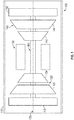
- FIG. 1 shows a simplified, cross-sectional view of a gas turbine engine 100 according to an embodiment.
- the engine 100 may be disposed in an engine housing 110 and may include an intake section 115, a compressor section 120, a combustion section 130, a turbine section 140, and an exhaust section 150.
- the compressor section 120, turbine section 140 and exhaust section 150 are operably coupled to a shaft assembly 160 for rotation within the housing 110.
- a fluid is drawn into the engine housing 110 through the intake section 115 and into the compressor section 120.
- the compressor section 120 includes an axial compressor 122 which may include one or more axial stages and a centrifugal compressor 124 that increases the pressure of the fluid entering the engine 100. Compression of the fluid may also result in heating of the fluid through the compressor section 120.
- the compressor section 120 is in fluid communication with the combustion section 130 and directs the compressed fluid into a combustion chamber where the compressed fluid is mixed with fuel and combusted in the combustion chamber. Hot exhaust fluids are then directed into the turbine section 140. The hot exhaust fluids expand through and rotate the turbine section 140 prior to being exhausted through the exhaust section 150 of the engine 100.
- the turbine section 140 rotates to drive equipment in the engine 100 via rotors or spools concentrically disposed about an axis of rotation 170 within the shaft assembly 160.
- the turbine section 140 may include one or more rotors 142, 144 driven by the expanding exhaust fluids to rotate to the shaft assembly 160 and drive the compressor section 120 including the axial compressor section 122 and the centrifugal compressor section 124.
- FIG. 1 depicts an exemplary configuration having an axi-centrifugal compressor core in a turboshaft engine, other embodiments may have alternate configurations.
- the exemplary embodiments discussed herein are not intended to be limited to a turboshaft engine, but rather may be readily adapted for use in other types of turbine engines including but not limited to turbofan and turboprop engines.
- FIG. 2 is a more detailed partial cross-sectional view of the compressor section 120 and a portion of the shaft assembly 160 of the engine 100 shown in FIG. 1 in accordance with an exemplary embodiment.
- FIG. 2 only half the cross-sectional view of the compressor section 120 is shown; the other half would be substantially rotationally symmetric about a centerline and axis of rotation 170. Additionally, certain aspects of the engine 100 may not be shown in FIG. 2 , or only schematically shown, for clarity in the relevant description of exemplary embodiments.
- the compressor section 120 defines a meanline flow path 180 (indicated by the long dash - short dash - short dash line) from a compressor inlet 182 through the axial compressor section 122 and the centrifugal compressor section 124 to a compressor exit 184, which is in fluid communication with the combustion section 130 (not shown in FIG. 2 ).
- the axial compressor section 122 leads into the centrifugal compressor section 124 such that an exit 186 of the axial compressor section 122 is in fluid communication with an inlet 186 of the centrifugal compressor 124.
- Fig. 2 illustrates a simplified cross-section through the compressor section 120, and that other features may be included in the compressor section 120 along the flow path 180 as dictated by the specification and constraints associated with a particular intended use.
- the axial compressor section 122 progressively compresses fluids flowing generally axially (i.e., parallel to axis 170) along the flow path 180.
- the axial compressor section 122 includes one or more axial compressor stages 122.1, 122.2, 122.3.
- the axial compressor section 122 includes one or more stator assemblies 190, 192, 194, 196 and one or more blade assemblies 200, 202, 204.
- the stator assemblies 190, 192, 194, 196 may include a plurality of stator vanes arranged in one or more vane rows which are stationary with respect to the engine housing 110 and function to diffuse and direct the fluid through the flow path 180.
- the rotor assemblies 200, 202, 204 may include a plurality of rotor blades extending from a rotor hub 206 into the flow path 180 and configured in one or more blade rows which are rotatably driven on the shaft assembly 160. As the rotor assemblies 200, 202, 204 rotate, the fluid flowing across each blade row are incrementally compressed along the flow path 180.
- stator and rotor assemblies illustrated in Fig. 2 , and that other configurations for the axial compressor section 122 are contemplated within the scope of the subject matter described and claimed herein. Modifications may include but are not limited to the use of multiple stators or double row stators within a given axial compressor stage, variable stator vanes, or struts.
- the centrifugal compressor section 124 compresses the fluid and directs the flow radially outward (i.e., in a direction which increases in a radial direction away from the axis 170) through an impeller assembly 210 driven on the shaft assembly 160.
- the rotor assemblies 200, 202, 204 and the impeller assembly 210 shown in FIG. 2 are coupled to a common drive shaft for co-rotation.
- other drive shaft configurations may be used for operantly coupling the axial compressor section 122 and the centrifugal compressor section 124 at a various drive ratio.
- one or more of the rotor assemblies 200, 202, 204 may be coupled for co-rotation, while the remaining rotor assemblies 200, 202, 204 and the impeller assembly 210 are not coupled for co-rotation.
- one or more of the rotor assemblies 200, 202, 204 and the impeller assembly 210 may be coupled for co-rotation.
- the shaft assembly 160 may include counter rotating shafts for the axial compressor section 124 and the centrifugal compressor assembly 126, or for the various axial compressor stages 122.1, 122.2, 122.3.
- the axial compressor section 122 includes a first stage 122.1 immediately downstream of the compressor inlet 182, a second stage 122.2 downstream of the first stage 122.1, and a third stage 122.3 downstream of the second stage 122.2.
- Each of the axial compressor stages 122.1, 122.2, 122.3 contributes to a pressure rise from the compressor inlet 182 to the axial compressor exit 186.
- the performance of the axial compressor section 122 can be characterized according to a first pressure rise (TPR A ) and a first pressure ratio (PR ax ) across the axial compressor section 122, as well as the pressure ratio per axial stage 122.1, 122.2, 122.3 (PR/stage ax) as provided below:
- a proportioned distribution of pressure rise across the axial stage compressor 122 and the centrifugal compressor 124, as well as across axial stage 122.1, 122.2, 122.3 i.e., stage matching
- the spanwise gradient of pressure rise across each axial stage should be configured to maximize the overall pressure rise attained. While a basic axial compressor section 122 has been illustrated and described herein, one skilled in the art will understand that additional compressor elements may be included to ensure that the axi-centrifugal compressor 120 satisfies the tuning and loading factors over the range of expected operating conditions.
- stability enhancing devices such as rotor tip casing treatments; variable stagger inlet guide vanes and stators; boundary layer separation control devices such as fluidic actuators (suction and blowing), vortex generators and plasma actuators placed on the end walls and/or airfoils to control destabilizing boundary layer separations; and airflow bleed (in or out) may be used to modify the stage matching at different operating conditions.
- boundary layer separation control devices such as fluidic actuators (suction and blowing), vortex generators and plasma actuators placed on the end walls and/or airfoils to control destabilizing boundary layer separations
- airflow bleed in or out
- a compressor section 120 satisfying both of these conditions effectively distributes the pressure rise among the axial compressor stage 122 and the centrifugal compressor section 124 so that the compressor section 120 may achieve the desired overall pressure rise with fewer stages, lighter weight and lower cost as compared to conventional compressor sections.
- a compressor section 120 with a tuning factor within a range between 2.8 and 4.5 and a loading factor within a range between 0.6 and 0.8 achieves a relatively high pressure rise across the axial compressor section by providing a high level of pressure rise on each individual axial stage, while avoiding detrimental aerodynamic over-loading of any axial stage.
- the result is a compact and efficient compressor section in which the axial compressor section is shorter, lighter, lower cost and higher performance, and the centrifugal compressor section is smaller in diameter and lower in weight.
- pressure as used herein is intended to mean a total pressure at a given location, for example the total pressure at an inlet or exit of either the axial compressor section or the centrifugal compressor section.
- Total pressure refers to the sum of static pressure and dynamic pressure as expressed by Bernoulli's principle. Any contribution attributable to gravitational head may also be included in the “total pressure.” Accordingly, the terms “pressure rise” and “pressure ratio” are also considered in terms of total pressures, unless explicitly indicated otherwise.
Landscapes
- Engineering & Computer Science (AREA)
- Mechanical Engineering (AREA)
- General Engineering & Computer Science (AREA)
- Chemical & Material Sciences (AREA)
- Combustion & Propulsion (AREA)
- Physics & Mathematics (AREA)
- Fluid Mechanics (AREA)
- Structures Of Non-Positive Displacement Pumps (AREA)
Claims (4)
- Axi-Zentrifugalverdichter für ein Gasturbinenantriebssystem (100) für ein Flugzeug, umfassend:ein Gehäuse (110); undeinen Verdichter (120), der drehbar auf einer Wellenanordnung (160) in dem Gehäuse gelagert ist und betreibbar ist, um ein Druckverhältnis entlang eines Strömungswegs (180) zwischen einem Verdichtereinlass (182) und einem Verdichterausgang (184) zu bewirken; wobei der Verdichter Folgendes umfasst:einen Axialverdichterabschnitt (122) mit mindestens einer axialen Stufe, die betreibbar ist, um ein erstes Druckverhältnis entlang des Strömungswegs zwischen dem Verdichtereinlass und einem ersten Abschnittausgang (186) zu bewirken;einen Zentrifugalverdichterabschnitt (124), der betreibbar ist, um ein zweites Druckverhältnis entlang des Strömungswegs zwischen einem zweiten Abschnitteinlass (186) und dem Verdichterausgang zu bewirken, wobei der dem Axialverdichterabschnitt zugeordnete erste Abschnittausgang direkt in den dem Zentrifugalabschnitt zugeordneten zweiten Abschnitteinlass entlang des Strömungswegs führt;wobei der Verdichter einen Abstimmfaktor aufweist, der die folgende Bedingung über den Bereich von erwarteten Betriebsbedingungen erfüllt:
 PRax das erste Druckverhältnis ist undPRc das zweite Druckverhältnis ist;und einen Belastungsfaktor aufweist, der die folgende Bedingung über den Bereich von erwarteten Betriebsbedingungen erfüllt:
n die Anzahl der axialen Stufen im Axialverdichterabschnitt ist,
und wobei:der Axialverdichterabschnitt mehrere axiale Stufen (122.1; 122.2; 122.3) in dem Axialverdichterabschnitt umfasst;jede der mehreren axialen Stufen mindestens eine Statoranordnung (190; 192; 194; 196) und eine Rotoranordnung (200; 202; 204) umfasst, die betriebsmäßig mit der Wellenanordnung zur Drehung relativ zu der Statoranordnung gekoppelt ist;die mehreren Rotoranordnungen zur gemeinsamen Drehung an der Wellenanordnung gekoppelt sind;die Wellenanordnung den Axialverdichterabschnitt und den Zentrifugalverdichterabschnitt betriebsmäßig zur gemeinsamen Drehung darauf koppelt; unddie mehreren axialen Stufen zur gemeinsamen Drehung mit dem Zentrifugalverdichterabschnitt gekoppelt sind. - Axi-Zentrifugalverdichter nach Anspruch 1, wobei der Abstimmfaktor in einem Bereich zwischen 3,5 und 4,0 liegt oder der Belastungsfaktor in einem Bereich zwischen 0,65 und 0,75 liegt.
- Verfahren zum Betreiben eines Verdichters entlang eines Strömungswegs (180) in einem Gasturbinenantriebssystem (100) für ein Flugzeug, umfassend:Ansaugen eines Fluids entlang des Strömungswegs durch einen ersten Einlass (182);Verdichten des Fluids entlang des Strömungswegs in einem Axialverdichterabschnitt (122) mit mindestens einer axialen Stufe nachgelagert von dem ersten Einlass (182) zu einem ersten Ausgang (186) in dem Axialverdichterabschnitt, sodass:

 PI1 der Druck an dem ersten Einlass ist,PE1 der Druck an dem ersten Ausgang ist undn die Anzahl der axialen Stufen ist;Übertragen des Fluids von dem ersten Ausgang in einen zweiten Einlass (186) entlang des Strömungswegs;Verdichten des Fluids entlang des Strömungswegs in einem Zentrifugalverdichter nachgelagert von dem zweiten Einlass zu einem zweiten Auslass (184) des Zentrifugalverdichterabschnitts, sodass:
 PI2 der Druck an dem zweiten Einlass ist undPE2 der Druck an dem zweiten Ausgang ist;wobei das Fluid gemäß den folgenden Bedingungen über den Bereich von erwarteten Betriebsbedingungen verdichtet wird:
 das Fluid in mehreren axialen Stufen (122.1; 122.2; 122.3) entlang des Strömungswegs in dem Axialverdichterabschnitt verdichtet wird;die mehreren axialen Stufen auf einer Wellenanordnung (160) gemeinsam gedreht werden;der Axialverdichter und die Zentrifugalverdichterabschnitte auf der Wellenanordnung gemeinsam gedreht werden; unddie mehreren axialen Stufen mit dem Zentrifugalverdichterabschnitt gemeinsam gedreht werden.
 - Verfahren nach Anspruch 3, wobei das Fluid gemäß mindestens einer der folgenden Bedingungen verdichtet wird:


Applications Claiming Priority (1)
| Application Number | Priority Date | Filing Date | Title |
|---|---|---|---|
| US15/079,538 US20170276070A1 (en) | 2016-03-24 | 2016-03-24 | Axi-centrifugal compressor |
Publications (2)
| Publication Number | Publication Date |
|---|---|
| EP3222854A1 EP3222854A1 (de) | 2017-09-27 |
| EP3222854B1 true EP3222854B1 (de) | 2020-07-01 |
Family
ID=58046542
Family Applications (1)
| Application Number | Title | Priority Date | Filing Date |
|---|---|---|---|
| EP17156153.3A Active EP3222854B1 (de) | 2016-03-24 | 2017-02-14 | Axi-zentrifugalverdichter |
Country Status (2)
| Country | Link |
|---|---|
| US (2) | US20170276070A1 (de) |
| EP (1) | EP3222854B1 (de) |
Families Citing this family (11)
| Publication number | Priority date | Publication date | Assignee | Title |
|---|---|---|---|---|
| US10982551B1 (en) | 2012-09-14 | 2021-04-20 | Raytheon Technologies Corporation | Turbomachine blade |
| GB2551551B (en) * | 2016-06-22 | 2018-09-05 | Rolls Royce Plc | Gas Turbine Engine |
| GB2551552B (en) * | 2016-06-22 | 2018-10-03 | Rolls Royce Plc | An aircraft gas turbine engine comprising non-coaxial propulsors driven by an engine core comprising two axially spaced core modules |
| US10697304B1 (en) * | 2017-01-17 | 2020-06-30 | Raytheon Technologies Corporation | Gas turbine engine airfoil frequency design |
| US11199096B1 (en) | 2017-01-17 | 2021-12-14 | Raytheon Technologies Corporation | Turbomachine blade |
| US11261737B1 (en) | 2017-01-17 | 2022-03-01 | Raytheon Technologies Corporation | Turbomachine blade |
| US10815826B1 (en) * | 2017-01-17 | 2020-10-27 | Raytheon Technologies Corporation | Gas turbine engine airfoil frequency design |
| US10415465B2 (en) * | 2017-12-21 | 2019-09-17 | United Technologies Corporation | Axial compressor with inter-stage centrifugal compressor |
| WO2022085024A1 (en) * | 2020-10-22 | 2022-04-28 | Indian Institute Of Technology, Kharagpur | Axial-centrifugal contra-rotating light weight, compact compression system. |
| US11549463B2 (en) * | 2021-02-22 | 2023-01-10 | General Electric Company | Compact low-pressure compressor |
| US11946474B2 (en) | 2021-10-14 | 2024-04-02 | Honeywell International Inc. | Gas turbine engine with compressor bleed system for combustor start assist |
Citations (1)
| Publication number | Priority date | Publication date | Assignee | Title |
|---|---|---|---|---|
| US20140003928A1 (en) * | 2012-06-29 | 2014-01-02 | Rolls-Royce Plc | Spool for turbo machinery |
Family Cites Families (3)
| Publication number | Priority date | Publication date | Assignee | Title |
|---|---|---|---|---|
| GB704856A (en) * | 1950-04-24 | 1954-03-03 | Rolls Royce | Improvements relating to air compressors |
| US4653976A (en) * | 1982-09-30 | 1987-03-31 | General Electric Company | Method of compressing a fluid flow in a multi stage centrifugal impeller |
| CN106687666B (zh) * | 2014-09-12 | 2019-07-09 | 通用电气公司 | 具有可变出口导向轮叶的轴流离心式压缩机 |
-
2016
- 2016-03-24 US US15/079,538 patent/US20170276070A1/en not_active Abandoned
-
2017
- 2017-02-14 EP EP17156153.3A patent/EP3222854B1/de active Active
-
2018
- 2018-08-06 US US16/056,101 patent/US20180355791A1/en not_active Abandoned
Patent Citations (1)
| Publication number | Priority date | Publication date | Assignee | Title |
|---|---|---|---|---|
| US20140003928A1 (en) * | 2012-06-29 | 2014-01-02 | Rolls-Royce Plc | Spool for turbo machinery |
Also Published As
| Publication number | Publication date |
|---|---|
| US20170276070A1 (en) | 2017-09-28 |
| US20180355791A1 (en) | 2018-12-13 |
| EP3222854A1 (de) | 2017-09-27 |
Similar Documents
| Publication | Publication Date | Title |
|---|---|---|
| EP3222854B1 (de) | Axi-zentrifugalverdichter | |
| US11098731B2 (en) | Grooved shroud casing treatment for high pressure compressor in a turbine engine | |
| CN107956598B (zh) | 燃气涡轮发动机 | |
| US9033668B2 (en) | Impeller | |
| US20160032826A1 (en) | Turbofan aircraft engine | |
| EP3249232B1 (de) | Kompressionssystem für einen turbinenmotor | |
| US20160017797A1 (en) | Turbofan aircraft engine | |
| US10316681B2 (en) | System and method for domestic bleed circuit seals within a turbine | |
| EP3061975B1 (de) | Axialverdichter mit fluidrückführung | |
| EP2679783A2 (de) | Rotor für Turbomaschine | |
| US20170298742A1 (en) | Turbine engine airfoil bleed pumping | |
| US20180216576A1 (en) | Supersonic turbofan engine | |
| EP2725233A1 (de) | Laufschaufel für einen Verdichter | |
| CN112412873B (zh) | 具有弦向叶片厚度变化的叶轮 | |
| CN111630250A (zh) | 涡轮 | |
| US12221894B2 (en) | Compressor with anti-ice inlet | |
| US11401835B2 (en) | Turbine center frame | |
| US11781504B2 (en) | Bleed plenum for compressor section | |
| US20260036052A1 (en) | Impeller splitter backsweep | |
| CN116457560B (zh) | 具有改善的推进效率的航空推进系统 | |
| US20260036133A1 (en) | Aircraft gas turbine engine impeller with a trailing edge that is non-linear or angled or irregularly-shaped | |
| EP4707534A1 (de) | Kompressor mit gehàuseöffnungen und mit teilweise geneigter schaufelvorderkante für gasturbinenmotor |
Legal Events
| Date | Code | Title | Description |
|---|---|---|---|
| PUAI | Public reference made under article 153(3) epc to a published international application that has entered the european phase |
Free format text: ORIGINAL CODE: 0009012 |
|
| STAA | Information on the status of an ep patent application or granted ep patent |
Free format text: STATUS: REQUEST FOR EXAMINATION WAS MADE |
|
| 17P | Request for examination filed |
Effective date: 20170214 |
|
| AK | Designated contracting states |
Kind code of ref document: A1 Designated state(s): AL AT BE BG CH CY CZ DE DK EE ES FI FR GB GR HR HU IE IS IT LI LT LU LV MC MK MT NL NO PL PT RO RS SE SI SK SM TR |
|
| AX | Request for extension of the european patent |
Extension state: BA ME |
|
| STAA | Information on the status of an ep patent application or granted ep patent |
Free format text: STATUS: EXAMINATION IS IN PROGRESS |
|
| 17Q | First examination report despatched |
Effective date: 20191008 |
|
| GRAP | Despatch of communication of intention to grant a patent |
Free format text: ORIGINAL CODE: EPIDOSNIGR1 |
|
| STAA | Information on the status of an ep patent application or granted ep patent |
Free format text: STATUS: GRANT OF PATENT IS INTENDED |
|
| INTG | Intention to grant announced |
Effective date: 20200310 |
|
| GRAS | Grant fee paid |
Free format text: ORIGINAL CODE: EPIDOSNIGR3 |
|
| GRAA | (expected) grant |
Free format text: ORIGINAL CODE: 0009210 |
|
| STAA | Information on the status of an ep patent application or granted ep patent |
Free format text: STATUS: THE PATENT HAS BEEN GRANTED |
|
| AK | Designated contracting states |
Kind code of ref document: B1 Designated state(s): AL AT BE BG CH CY CZ DE DK EE ES FI FR GB GR HR HU IE IS IT LI LT LU LV MC MK MT NL NO PL PT RO RS SE SI SK SM TR |
|
| REG | Reference to a national code |
Ref country code: AT Ref legal event code: REF Ref document number: 1286443 Country of ref document: AT Kind code of ref document: T Effective date: 20200715 Ref country code: CH Ref legal event code: EP |
|
| REG | Reference to a national code |
Ref country code: IE Ref legal event code: FG4D |
|
| REG | Reference to a national code |
Ref country code: DE Ref legal event code: R096 Ref document number: 602017018869 Country of ref document: DE |
|
| REG | Reference to a national code |
Ref country code: LT Ref legal event code: MG4D |
|
| PG25 | Lapsed in a contracting state [announced via postgrant information from national office to epo] |
Ref country code: BG Free format text: LAPSE BECAUSE OF FAILURE TO SUBMIT A TRANSLATION OF THE DESCRIPTION OR TO PAY THE FEE WITHIN THE PRESCRIBED TIME-LIMIT Effective date: 20201001 |
|
| REG | Reference to a national code |
Ref country code: NL Ref legal event code: MP Effective date: 20200701 |
|
| REG | Reference to a national code |
Ref country code: AT Ref legal event code: MK05 Ref document number: 1286443 Country of ref document: AT Kind code of ref document: T Effective date: 20200701 |
|
| PG25 | Lapsed in a contracting state [announced via postgrant information from national office to epo] |
Ref country code: HR Free format text: LAPSE BECAUSE OF FAILURE TO SUBMIT A TRANSLATION OF THE DESCRIPTION OR TO PAY THE FEE WITHIN THE PRESCRIBED TIME-LIMIT Effective date: 20200701 Ref country code: SE Free format text: LAPSE BECAUSE OF FAILURE TO SUBMIT A TRANSLATION OF THE DESCRIPTION OR TO PAY THE FEE WITHIN THE PRESCRIBED TIME-LIMIT Effective date: 20200701 Ref country code: ES Free format text: LAPSE BECAUSE OF FAILURE TO SUBMIT A TRANSLATION OF THE DESCRIPTION OR TO PAY THE FEE WITHIN THE PRESCRIBED TIME-LIMIT Effective date: 20200701 Ref country code: CZ Free format text: LAPSE BECAUSE OF FAILURE TO SUBMIT A TRANSLATION OF THE DESCRIPTION OR TO PAY THE FEE WITHIN THE PRESCRIBED TIME-LIMIT Effective date: 20200701 Ref country code: NO Free format text: LAPSE BECAUSE OF FAILURE TO SUBMIT A TRANSLATION OF THE DESCRIPTION OR TO PAY THE FEE WITHIN THE PRESCRIBED TIME-LIMIT Effective date: 20201001 Ref country code: AT Free format text: LAPSE BECAUSE OF FAILURE TO SUBMIT A TRANSLATION OF THE DESCRIPTION OR TO PAY THE FEE WITHIN THE PRESCRIBED TIME-LIMIT Effective date: 20200701 Ref country code: GR Free format text: LAPSE BECAUSE OF FAILURE TO SUBMIT A TRANSLATION OF THE DESCRIPTION OR TO PAY THE FEE WITHIN THE PRESCRIBED TIME-LIMIT Effective date: 20201002 Ref country code: PT Free format text: LAPSE BECAUSE OF FAILURE TO SUBMIT A TRANSLATION OF THE DESCRIPTION OR TO PAY THE FEE WITHIN THE PRESCRIBED TIME-LIMIT Effective date: 20201102 Ref country code: FI Free format text: LAPSE BECAUSE OF FAILURE TO SUBMIT A TRANSLATION OF THE DESCRIPTION OR TO PAY THE FEE WITHIN THE PRESCRIBED TIME-LIMIT Effective date: 20200701 Ref country code: LT Free format text: LAPSE BECAUSE OF FAILURE TO SUBMIT A TRANSLATION OF THE DESCRIPTION OR TO PAY THE FEE WITHIN THE PRESCRIBED TIME-LIMIT Effective date: 20200701 |
|
| PG25 | Lapsed in a contracting state [announced via postgrant information from national office to epo] |
Ref country code: IS Free format text: LAPSE BECAUSE OF FAILURE TO SUBMIT A TRANSLATION OF THE DESCRIPTION OR TO PAY THE FEE WITHIN THE PRESCRIBED TIME-LIMIT Effective date: 20201101 Ref country code: LV Free format text: LAPSE BECAUSE OF FAILURE TO SUBMIT A TRANSLATION OF THE DESCRIPTION OR TO PAY THE FEE WITHIN THE PRESCRIBED TIME-LIMIT Effective date: 20200701 Ref country code: PL Free format text: LAPSE BECAUSE OF FAILURE TO SUBMIT A TRANSLATION OF THE DESCRIPTION OR TO PAY THE FEE WITHIN THE PRESCRIBED TIME-LIMIT Effective date: 20200701 Ref country code: RS Free format text: LAPSE BECAUSE OF FAILURE TO SUBMIT A TRANSLATION OF THE DESCRIPTION OR TO PAY THE FEE WITHIN THE PRESCRIBED TIME-LIMIT Effective date: 20200701 |
|
| PG25 | Lapsed in a contracting state [announced via postgrant information from national office to epo] |
Ref country code: NL Free format text: LAPSE BECAUSE OF FAILURE TO SUBMIT A TRANSLATION OF THE DESCRIPTION OR TO PAY THE FEE WITHIN THE PRESCRIBED TIME-LIMIT Effective date: 20200701 |
|
| REG | Reference to a national code |
Ref country code: DE Ref legal event code: R097 Ref document number: 602017018869 Country of ref document: DE |
|
| PG25 | Lapsed in a contracting state [announced via postgrant information from national office to epo] |
Ref country code: DK Free format text: LAPSE BECAUSE OF FAILURE TO SUBMIT A TRANSLATION OF THE DESCRIPTION OR TO PAY THE FEE WITHIN THE PRESCRIBED TIME-LIMIT Effective date: 20200701 Ref country code: RO Free format text: LAPSE BECAUSE OF FAILURE TO SUBMIT A TRANSLATION OF THE DESCRIPTION OR TO PAY THE FEE WITHIN THE PRESCRIBED TIME-LIMIT Effective date: 20200701 Ref country code: IT Free format text: LAPSE BECAUSE OF FAILURE TO SUBMIT A TRANSLATION OF THE DESCRIPTION OR TO PAY THE FEE WITHIN THE PRESCRIBED TIME-LIMIT Effective date: 20200701 Ref country code: EE Free format text: LAPSE BECAUSE OF FAILURE TO SUBMIT A TRANSLATION OF THE DESCRIPTION OR TO PAY THE FEE WITHIN THE PRESCRIBED TIME-LIMIT Effective date: 20200701 Ref country code: SM Free format text: LAPSE BECAUSE OF FAILURE TO SUBMIT A TRANSLATION OF THE DESCRIPTION OR TO PAY THE FEE WITHIN THE PRESCRIBED TIME-LIMIT Effective date: 20200701 |
|
| PLBE | No opposition filed within time limit |
Free format text: ORIGINAL CODE: 0009261 |
|
| STAA | Information on the status of an ep patent application or granted ep patent |
Free format text: STATUS: NO OPPOSITION FILED WITHIN TIME LIMIT |
|
| PG25 | Lapsed in a contracting state [announced via postgrant information from national office to epo] |
Ref country code: AL Free format text: LAPSE BECAUSE OF FAILURE TO SUBMIT A TRANSLATION OF THE DESCRIPTION OR TO PAY THE FEE WITHIN THE PRESCRIBED TIME-LIMIT Effective date: 20200701 |
|
| 26N | No opposition filed |
Effective date: 20210406 |
|
| PG25 | Lapsed in a contracting state [announced via postgrant information from national office to epo] |
Ref country code: SK Free format text: LAPSE BECAUSE OF FAILURE TO SUBMIT A TRANSLATION OF THE DESCRIPTION OR TO PAY THE FEE WITHIN THE PRESCRIBED TIME-LIMIT Effective date: 20200701 |
|
| PG25 | Lapsed in a contracting state [announced via postgrant information from national office to epo] |
Ref country code: SI Free format text: LAPSE BECAUSE OF FAILURE TO SUBMIT A TRANSLATION OF THE DESCRIPTION OR TO PAY THE FEE WITHIN THE PRESCRIBED TIME-LIMIT Effective date: 20200701 |
|
| PG25 | Lapsed in a contracting state [announced via postgrant information from national office to epo] |
Ref country code: MC Free format text: LAPSE BECAUSE OF FAILURE TO SUBMIT A TRANSLATION OF THE DESCRIPTION OR TO PAY THE FEE WITHIN THE PRESCRIBED TIME-LIMIT Effective date: 20200701 |
|
| GBPC | Gb: european patent ceased through non-payment of renewal fee |
Effective date: 20210214 |
|
| REG | Reference to a national code |
Ref country code: BE Ref legal event code: MM Effective date: 20210228 |
|
| PG25 | Lapsed in a contracting state [announced via postgrant information from national office to epo] |
Ref country code: CH Free format text: LAPSE BECAUSE OF NON-PAYMENT OF DUE FEES Effective date: 20210228 Ref country code: LU Free format text: LAPSE BECAUSE OF NON-PAYMENT OF DUE FEES Effective date: 20210214 Ref country code: LI Free format text: LAPSE BECAUSE OF NON-PAYMENT OF DUE FEES Effective date: 20210228 |
|
| PG25 | Lapsed in a contracting state [announced via postgrant information from national office to epo] |
Ref country code: GB Free format text: LAPSE BECAUSE OF NON-PAYMENT OF DUE FEES Effective date: 20210214 Ref country code: FR Free format text: LAPSE BECAUSE OF NON-PAYMENT OF DUE FEES Effective date: 20210228 Ref country code: IE Free format text: LAPSE BECAUSE OF NON-PAYMENT OF DUE FEES Effective date: 20210214 |
|
| PG25 | Lapsed in a contracting state [announced via postgrant information from national office to epo] |
Ref country code: BE Free format text: LAPSE BECAUSE OF NON-PAYMENT OF DUE FEES Effective date: 20210228 |
|
| PG25 | Lapsed in a contracting state [announced via postgrant information from national office to epo] |
Ref country code: HU Free format text: LAPSE BECAUSE OF FAILURE TO SUBMIT A TRANSLATION OF THE DESCRIPTION OR TO PAY THE FEE WITHIN THE PRESCRIBED TIME-LIMIT; INVALID AB INITIO Effective date: 20170214 |
|
| PG25 | Lapsed in a contracting state [announced via postgrant information from national office to epo] |
Ref country code: CY Free format text: LAPSE BECAUSE OF FAILURE TO SUBMIT A TRANSLATION OF THE DESCRIPTION OR TO PAY THE FEE WITHIN THE PRESCRIBED TIME-LIMIT Effective date: 20200701 |
|
| P01 | Opt-out of the competence of the unified patent court (upc) registered |
Effective date: 20230525 |
|
| PG25 | Lapsed in a contracting state [announced via postgrant information from national office to epo] |
Ref country code: MK Free format text: LAPSE BECAUSE OF FAILURE TO SUBMIT A TRANSLATION OF THE DESCRIPTION OR TO PAY THE FEE WITHIN THE PRESCRIBED TIME-LIMIT Effective date: 20200701 |
|
| PG25 | Lapsed in a contracting state [announced via postgrant information from national office to epo] |
Ref country code: TR Free format text: LAPSE BECAUSE OF FAILURE TO SUBMIT A TRANSLATION OF THE DESCRIPTION OR TO PAY THE FEE WITHIN THE PRESCRIBED TIME-LIMIT Effective date: 20200701 |
|
| PG25 | Lapsed in a contracting state [announced via postgrant information from national office to epo] |
Ref country code: MT Free format text: LAPSE BECAUSE OF FAILURE TO SUBMIT A TRANSLATION OF THE DESCRIPTION OR TO PAY THE FEE WITHIN THE PRESCRIBED TIME-LIMIT Effective date: 20200701 |
|
| PGFP | Annual fee paid to national office [announced via postgrant information from national office to epo] |
Ref country code: DE Payment date: 20260220 Year of fee payment: 10 |