EP3222805B1 - Fenster mit einem gegen einen rahmen schwenkbaren flügel - Google Patents
Fenster mit einem gegen einen rahmen schwenkbaren flügel Download PDFInfo
- Publication number
- EP3222805B1 EP3222805B1 EP17159812.1A EP17159812A EP3222805B1 EP 3222805 B1 EP3222805 B1 EP 3222805B1 EP 17159812 A EP17159812 A EP 17159812A EP 3222805 B1 EP3222805 B1 EP 3222805B1
- Authority
- EP
- European Patent Office
- Prior art keywords
- electrical component
- hollow chamber
- window according
- chamber profile
- electrical
- Prior art date
- Legal status (The legal status is an assumption and is not a legal conclusion. Google has not performed a legal analysis and makes no representation as to the accuracy of the status listed.)
- Active
Links
Images


Classifications
-
- E—FIXED CONSTRUCTIONS
- E06—DOORS, WINDOWS, SHUTTERS, OR ROLLER BLINDS IN GENERAL; LADDERS
- E06B—FIXED OR MOVABLE CLOSURES FOR OPENINGS IN BUILDINGS, VEHICLES, FENCES OR LIKE ENCLOSURES IN GENERAL, e.g. DOORS, WINDOWS, BLINDS, GATES
- E06B7/00—Special arrangements or measures in connection with doors or windows
- E06B7/28—Other arrangements on doors or windows, e.g. door-plates, windows adapted to carry plants, hooks for window cleaners
-
- E—FIXED CONSTRUCTIONS
- E05—LOCKS; KEYS; WINDOW OR DOOR FITTINGS; SAFES
- E05C—BOLTS OR FASTENING DEVICES FOR WINGS, SPECIALLY FOR DOORS OR WINDOWS
- E05C9/00—Arrangements of simultaneously actuated bolts or other securing devices at well-separated positions on the same wing
- E05C9/06—Arrangements of simultaneously actuated bolts or other securing devices at well-separated positions on the same wing with three or more sliding bars
- E05C9/063—Arrangements of simultaneously actuated bolts or other securing devices at well-separated positions on the same wing with three or more sliding bars extending along three or more sides of the wing or frame
- E05C9/066—Locks for windows or doors specially adapted for tilt and turn
-
- E—FIXED CONSTRUCTIONS
- E05—LOCKS; KEYS; WINDOW OR DOOR FITTINGS; SAFES
- E05B—LOCKS; ACCESSORIES THEREFOR; HANDCUFFS
- E05B47/00—Operating or controlling locks or other fastening devices by electric or magnetic means
- E05B2047/0048—Circuits, feeding, monitoring
- E05B2047/0057—Feeding
- E05B2047/0064—Feeding by solar cells
-
- E—FIXED CONSTRUCTIONS
- E05—LOCKS; KEYS; WINDOW OR DOOR FITTINGS; SAFES
- E05B—LOCKS; ACCESSORIES THEREFOR; HANDCUFFS
- E05B47/00—Operating or controlling locks or other fastening devices by electric or magnetic means
- E05B47/0001—Operating or controlling locks or other fastening devices by electric or magnetic means with electric actuators; Constructional features thereof
- E05B47/0012—Operating or controlling locks or other fastening devices by electric or magnetic means with electric actuators; Constructional features thereof with rotary electromotors
-
- E—FIXED CONSTRUCTIONS
- E05—LOCKS; KEYS; WINDOW OR DOOR FITTINGS; SAFES
- E05B—LOCKS; ACCESSORIES THEREFOR; HANDCUFFS
- E05B9/00—Lock casings or latch-mechanism casings ; Fastening locks or fasteners or parts thereof to the wing
- E05B9/08—Fastening locks or fasteners or parts thereof, e.g. the casings of latch-bolt locks or cylinder locks to the wing
-
- E—FIXED CONSTRUCTIONS
- E05—LOCKS; KEYS; WINDOW OR DOOR FITTINGS; SAFES
- E05C—BOLTS OR FASTENING DEVICES FOR WINGS, SPECIALLY FOR DOORS OR WINDOWS
- E05C9/00—Arrangements of simultaneously actuated bolts or other securing devices at well-separated positions on the same wing
- E05C9/008—Arrangements of simultaneously actuated bolts or other securing devices at well-separated positions on the same wing mounted in an elongate casing on the surface of the wing
Definitions
- the invention relates to a window with a sash pivotable against a frame and with at least one hollow chamber profile of the frame or sash, with an opening in the hollow chamber profile and with at least one electrical component inserted in the hollow chamber profile, the at least one electrical component having dimensions for insertion into the Has hollow profile over the opening.
- Such a window is for example from the WO 2012/055976 A2 known.
- a hollow chamber profile of the sash has an opening in a fold that points towards the frame. This opening is closed by a cover to be mounted separately.
- the wing also has a handle mounted remotely from the lid. This requires a great deal of effort to assemble the window, for example for the handle and the cover.
- wings are often composed of four mitered hollow chamber profiles. A horizontally arranged hollow chamber profile of the wing is thus covered at its end by a vertically arranged hollow chamber profile and is therefore not accessible from the vertical side.
- the creation of the opening in the vertical hollow chamber profile for mounting the electrical component in the horizontal hollow chamber profile requires a large structural effort, especially since the opening in the vertical hollow chamber profile must be exactly aligned with a hollow chamber in the horizontal hollow chamber profile. Furthermore, in the abutting corner area of the hollow chamber profiles, a partial area of a drive rod fitting is usually arranged, so that a cover often cannot be mounted.
- a window is known in which photovoltaic elements are arranged in front of recesses in a hollow chamber profile. Electrical lines or a storage element can be arranged within the hollow chamber profile. The recesses for the photovoltaic element are therefore inevitably arranged in visible areas of the hollow chamber profile and are therefore disruptive.
- the invention is based on the problem of developing a window of the type mentioned at the outset in such a way that it is particularly simple to construct and assemble together with the electrical component.
- an opening which is already arranged in the hollow profile, is used for the fitting part in order to mount the electrical component. This eliminates at least one additional work step for creating the opening. Furthermore, after the assembly of the electrical component, the opening is closed by the fitting part of the drive rod fitting that is to be fitted anyway. This makes the assembly of the electrical component particularly easy.
- the electrical current can be stored within the window if the electrical component arranged in the hollow chamber profile has an accumulator.
- the opening can be made very elongated if the opening is arranged on the bottom of a fitting groove provided for receiving a drive rod of a drive rod fitting that locks the sash in the frame. Since the fitting groove is covered by a faceplate anyway, the opening is no longer visible after the electrical component has been installed.
- the fitting part is designed as a drive gear for driving the drive rod fitting.
- Such an opening is usually already available for connecting a handle to the espagnolette fitting, so that the use of the electrical component does not cause any further weakening of the hollow chamber profile.
- an electric motor can be connected to the drive gear.
- the electrical component could, for example, be suspended in the hollow chamber profile. According to another advantageous development of the invention, it helps to simplify assembly if the electrical component is connected to an insertion aid before assembly and if a predetermined breaking point is arranged between the insertion aid and the electrical component.
- the insertion aid enables the electrical component to be mounted on almost any non-disruptive area of the hollow chamber profile. After assembly, the insertion aid is separated from the electrical component at the predetermined breaking point. This avoids disruptive components protruding into the opening.
- the electrical component is reliably held in the window after assembly if the electrical component has a holding element for fixing within the hollow chamber profile.
- the holding element could for example be clamped or glued to the hollow chamber profile.
- the holding element preferably has a screw hole for screwing to the hollow chamber profile. This screw connection is preferably arranged within the fitting groove and covered by the connecting rod fitting when the window is installed.
- the electrical component can be introduced into the hollow chamber profile via an opening of particularly small dimensions if the electrical component has an elongated shape and is designed to be flexible. If the electrical component has several cells of the accumulator, several cylindrical accumulators can be flexibly connected to one another.
- connection of individual cells of the accumulator of the electrical component could take place, for example, via an adhesive film.
- the electrical component having the individual cells of the accumulator has, however, according to one Another advantageous development of the invention has a particularly high stability when several individual cells of the accumulator of the electrical component are elastically connected to one another.
- a shrink film is particularly suitable for the elastic connection.
- the window can be equipped with extensive drive, monitoring and control devices if electrical lines connect several electrical components to a feed module for feeding electrical current.
- One of the electrical components preferably has an accumulator and another electrical component has an electric motor.
- the electric motor can be designed to drive the drive rod fitting or a blind device.
- the laying of the electrical lines is particularly convenient if the electrical lines are arranged in a glass rebate of the sash. Since mostly only small currents flow between the electrical components, the electrical lines can preferably be designed as flat cables in a particularly space-saving manner.
- the feed module could, for example, have an induction loop for inductive feed of the electrical current.
- the feed module could also have a mechanical plug contact.
- the window is designed to be particularly low-maintenance if the feed module has a solar cell for converting light into electrical current.
- Figure 1 shows a window with a sash 2 pivotable against a frame 1 and with a connecting rod fitting 3 for locking the sash 2 in the frame 1.
- the connecting rod fitting 3 has a drive gear 4 for driving a longitudinally displaceable connecting rod 5 and several locks 6 controllable by the connecting rod 5.
- the window has a feed module 7 with a solar cell 8 and an electrical component 9 with a switching element 10.
- FIG 2 shows the feed module 7 with the solar cell 8, the electrical component 9 having the switching element 10 and an electrical component 12 having an accumulator 11.
- the electrical components 9, 12 and the feed module 7 are connected to one another via electrical lines 13, 14.
- an electrical actuator (not shown) for driving the drive gear 4 of the drive rod fitting 3 Figure 1 arranged.
- the connecting rod fitting 3 can be controlled electrically.
- the electrical energy for controlling the connecting rod fitting 3 is generated by the solar cell 8 and stored in the accumulator 11.
- a darkening device with a blind can also be controlled by the switching element 10.
- FIG 3 shows the electrical component 12 having the accumulator 11 and the electrical component 9 having the switching element 10 with the electrical lines 13, 14 Figure 2 .
- the electrical component 10 having the accumulator 11 is connected to an insertion aid 15.
- the insertion aid 15 has a handle 16 for gripping with the hand and a cross-sectional constriction as a predetermined breaking point 17.
- the electrical component 12 having the accumulator 11 has a holding element 18 with a screw 19 for screwing to the wing 2 Insert electrical component 12 into wing 2. The retaining element 18 is then screwed to the wing 2. After assembly, the insertion aid 15 is broken off at the predetermined breaking point 17.
- the electrical component 12 having the accumulator 11 has a constriction 20 in the center, which separates two cells 21, 22 of the accumulator 11 from one another.
- the constriction 20 is designed to be elastic and enables the electrical component 12 having the accumulator 11 to be bent.
- Figure 4 shows a sectional view through the window Figure 1 along the line IV - IV.
- the wing 2 and frame 1 have hollow chamber profiles 23.
- the electrical component 12 having the accumulator 11 is arranged in a hollow chamber 24.
- the hollow chamber 24 has an opening 25 for mounting the drive gear 4, not shown, of the drive rod fitting 3.
- the opening 25 is located in a bottom 26 of a for receiving the in Figure 1
- the drive rod 5 shown provided fitting groove 27.
- the component 12 having the accumulator 11 is screwed to the wing 2 via the holding element 18.
- the electrical lines 14 to the feed module 7 are arranged in a glass rebate 28 of the leaf 2.
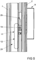
- Figure 5 shows a sectional view through the window Figure 1 along the line V - V that the electrical component having the accumulator 11 12 is designed to be elongated and can be introduced into the hollow chamber 24 even in very tight spaces due to its flexibility. Also in Figure 4 the drive gear 4 is not shown to clarify the drawing.
Landscapes
- Engineering & Computer Science (AREA)
- Mechanical Engineering (AREA)
- Civil Engineering (AREA)
- Structural Engineering (AREA)
- Power-Operated Mechanisms For Wings (AREA)
- Operating, Guiding And Securing Of Roll- Type Closing Members (AREA)
Description
- Die Erfindung betrifft ein Fenster mit einem gegen einen Rahmen schwenkbaren Flügel und mit zumindest einem Hohlkammerprofil des Rahmens oder des Flügels, mit einer Öffnung des Hohlkammerprofils und mit zumindest einem in dem Hohlkammerprofil eingesetzten elektrischen Bauteil, wobei das zumindest eine elektrische Bauteil Abmessungen zur Einführung in das Hohlkammerprofil über die Öffnung hat.
- Ein solches Fenster ist beispielsweise aus der
WO 2012/055976 A2 bekannt. Bei diesem Fenster hat ein Hohlkammerprofil des Flügels eine in einem Falz zum Rahmen weisende Öffnung. Diese Öffnung ist von einem separat zu montierenden Deckel verschlossen. Weiterhin hat der Flügel einen entfernt von dem Deckel montierten Handgriff. Dies erfordert einen hohen Montageaufwand des Fensters beispielsweise für den Handgriff und den Deckel. Weiterhin werden Flügel häufig von vier auf Gehrung geschnittenen Hohlkammerprofilen zusammengesetzt. Damit ist ein horizontal angeordnetes Hohlkammerprofil des Flügels an seinem Ende von einem vertikal angeordneten Hohlkammerprofil verdeckt und damit nicht von der vertikalen Seite zugänglich. Daher erfordert die Erzeugung der Öffnung im vertikalen Hohlkammerprofil zur Montage des elektrischen Bauteils im horizontalen Hohlkammerprofil einen großen baulichen Aufwand, zumal die Öffnung im vertikalen Hohlkammerprofil genau mit einer Hohlkammer im horizontalen Hohlkammerprofil fluchten muss. Weiterhin ist im aufeinander stoßenden Eckbereich der Hohlkammerprofile meist ein Teilbereich eines Treibstangenbeschlages angeordnet, so dass ein Deckel häufig nicht montiert werden kann. - Weiterhin ist aus der
EP 1 703 063 B1 ein Fenster bekannt, bei dem Photovoltaikelemente vor Ausnehmungen eines Hohlkammerprofils angeordnet sind. Elektrische Leitungen oder ein Speicherelement können innerhalb des Hohlkammerprofils angeordnet werden. Die Ausnehmungen für das Photovoltaikelement sind damit zwangsläufig an sichtbaren Bereichen des Hohlkammerprofils angeordnet und damit störend. - Der Erfindung liegt das Problem zugrunde, ein Fenster der eingangs genannten Art so weiter zu bilden, dass es zusammen mit dem elektrischen Bauteil besonders einfach aufgebaut und zu montieren ist.
- Dieses Problem wird erfindungsgemäß dadurch gelöst, dass die Öffnung, über die das zumindest eine elektrische Bauteil in das Hohlkammerprofil einführbar ist, von einem Beschlagteil eines den Flügel in dem Rahmen verriegelnden Treibstangenbeschlages verschlossen ist.
- Durch diese Gestaltung wird eine ohnehin in das Hohlprofil angeordnete Öffnung für das Beschlagteil verwendet, um das elektrische Bauteil zu montieren. Damit entfällt zumindest ein zusätzlicher Arbeitsgang für die Erzeugung der Öffnung. Weiterhin wird die Öffnung nach der Montage des elektrischen Bauteils von dem ohnehin zu montierenden Beschlagteil des Treibstangenbeschlages verschlossen. Damit gestaltet sich die Montage des elektrischen Bauteils besonders einfach.
- Meist benötigen Einrichtungen mit elektrischen Bauteilen eine Versorgung mit elektrischem Strom. Der elektrische Strom lässt sich gemäß einer vorteilhaften Weiterbildung der Erfindung innerhalb des Fensters speichern, wenn das in dem Hohlkammerprofil angeordnete elektrische Bauteil einen Akkumulator hat.
- Die Öffnung kann gemäß einer anderen vorteilhaften Weiterbildung der Erfindung sehr langgestreckt gestaltet sein, wenn die Öffnung am Boden einer zur Aufnahme einer Treibstange eines den Flügel in dem Rahmen verriegelnden Treibstangenbeschlages vorgesehenen Beschlagnut angeordnet ist. Da die Beschlagnut ohnehin von einer Stulpschiene abgedeckt ist, ist die Öffnung nach der Montage des elektrischen Bauteils nicht mehr sichtbar.
- Eine unerwünschte Schwächung des Hohlkammerprofils durch die Öffnung lässt sich gemäß einer anderen vorteilhaften Weiterbildung der Erfindung vermeiden, wenn das Beschlagteil als Antriebsgetriebe zum Antrieb des Treibstangenbeschlags ausgebildet ist. Eine solche Öffnung ist zur Anbindung einer Handhabe an den Treibstangenbeschlag meist ohnehin vorhanden, so dass der Einsatz des elektrischen Bauteils keine weitere Schwächung des Hohlkammerprofils hervorruft. Bei einem elektrischen Antrieb des Treibstangenbeschlages lässt sich ein Elektromotor an dem Antriebsgetriebe anschließen.
- Das elektrische Bauteil könnte beispielsweise in das Hohlkammerprofil eingehängt sein. Zur Vereinfachung der Montage trägt es gemäß einer anderen vorteilhaften Weiterbildung der Erfindung bei, wenn das elektrische Bauteil vor der Montage mit einer Einführhilfe verbunden ist und wenn zwischen der Einführhilfe und dem elektrischen Bauteil eine Sollbruchstelle angeordnet ist. Die Einführhilfe ermöglicht die Montage des elektrischen Bauteils an einen nahezu beliebigen und nicht störenden Bereich des Hohlkammerprofils. Nach der Montage wird die Einführhilfe an der Sollbruchstelle von dem elektrischen Bauteil getrennt. Damit werden störende, in die Öffnung hineinragende Bauteile vermieden.
- Das elektrische Bauteil ist gemäß einer anderen vorteilhaften Weiterbildung der Erfindung nach der Montage zuverlässig in dem Fenster gehalten, wenn das elektrische Bauteil ein Halteelement zur Fixierung innerhalb des Hohlkammerprofils aufweist. Das Halteelement könnte beispielsweise mit dem Hohlkammerprofil verklemmt oder verklebt werden. Vorzugsweise hat das Halteelement jedoch eine Schraubbohrung zur Verschraubung mit dem Hohlkammerprofil. Diese Verschraubung ist vorzugsweise innerhalb der Beschlagnut angeordnet und im montierten Zustand des Fensters von dem Treibstangenbeschlag verdeckt.
- Das elektrische Bauteil lässt sich gemäß einer anderen vorteilhaften Weiterbildung der Erfindung über eine besonders klein dimensionierte Öffnung in das Hohlkammerprofil einführen, wenn das elektrische Bauteil eine lang gestreckte Form aufweist und biegsam gestaltet ist. Wenn das elektrische Bauteil mehrere Zellen des Akkumulators aufweist, lassen sich mehrere zylindrische Akkumulatoren biegsam miteinander verbinden.
- Die Verbindung einzelner Zellen des Akkumulators des elektrischen Bauteils könnte beispielsweise über eine Klebefolie erfolgen. Das die einzelnen Zellen des Akkumulators aufweisende elektrische Bauteil weist jedoch gemäß einer anderen vorteilhaften Weiterbildung der Erfindung eine besonders hohe Stabilität auf, wenn mehrere einzelne Zellen des Akkumulators des elektrischen Bauteils elastisch miteinander verbunden sind. Zur elastischen Verbindung eignet sich insbesondere eine Schrumpffolie.
- Das Fenster lässt sich gemäß einer anderen vorteilhaften Weiterbildung der Erfindung mit umfangreichen Antriebs-, Überwachungs- und Steuereinrichtungen ausrüsten, wenn elektrische Leitungen mehrere elektrische Bauteile mit einem Einspeisemodul zur Einspeisung von elektrischem Strom verbinden. Vorzugsweise weist eines der elektrischen Bauteile einen Akkumulator und ein weiteres elektrisches Bauteil einen Elektromotor auf. Der Elektromotor kann dabei zum Antrieb des Treibstangenbeschlages oder einer Jalousieeinrichtung ausgebildet sein.
- Die Verlegung der elektrischen Leitungen gestaltet sich gemäß einer anderen vorteilhaften Weiterbildung der Erfindung besonders komfortabel, wenn die elektrischen Leitungen in einem Glasfalz des Flügels angeordnet sind. Da meist nur geringe Ströme zwischen den elektrischen Bauteilen fließen, können die elektrischen Leitungen vorzugsweise besonders platzsparend als Flachleitungen ausgebildet sein.
- Das Einspeisemodul könnte beispielsweise eine Induktionsschleife zur induktiven Einspeisung des elektrischen Stroms aufweisen. Ebenfalls könnte das Einspeisemodul einen mechanischen Steckkontakt haben. Das Fenster gestaltet sich jedoch gemäß einer anderen vorteilhaften Weiterbildung der Erfindung besonders wartungsarm, wenn das Einspeisemodul eine Solarzelle zur Umwandlung von Licht in elektrischen Strom aufweist.
- Die Erfindung lässt zahlreiche Ausführungsformen zu. Zur weiteren Verdeutlichung ihres Grundprinzips ist eine davon in der Zeichnung dargestellt und wird nachfolgend beschrieben. Diese zeigt in
- Fig. 1
- ein Fenster mit einer Solarzelle und mit einem elektrischen Schaltelement,
- Fig. 2
- die Solarzelle und das elektrische Schaltelement aus Figur 1 mit einem Akkumulator und elektrischen Leitungen,
- Fig. 3
- vergrößert den Akkumulator aus
Figur 2 mit einer Einführhilfe, - Fig. 4
- eine Schnittdarstellung durch das Fenster aus
Figur 1 entlang der Linie IV - IV, - Fig. 5
- eine Schnittdarstellung durch das Fenster aus
Figur 1 entlang der Linie V - V. -
Figur 1 zeigt ein Fenster mit einem gegen einen Rahmen 1 schwenkbaren Flügel 2 und mit einem Treibstangenbeschlag 3 zur Verriegelung des Flügels 2 in dem Rahmen 1. Der Treibstangenbeschlag 3 hat ein Antriebsgetriebe 4 zum Antrieb einer längsverschieblichen Treibstange 5 und mehrere von der Treibstange 5 ansteuerbare Verschlüsse 6. Weiterhin hat das Fenster ein Einspeisemodul 7 mit einer Solarzelle 8 und ein elektrisches Bauteil 9 mit einem Schaltelement 10. -
Figur 2 zeigt das Einspeisemodul 7 mit der Solarzelle 8, das das Schaltelement 10 aufweisende elektrische Bauteil 9 und ein einen Akkumulator 11 aufweisendes elektrisches Bauteil 12. Die elektrischen Bauteile 9, 12 und das Einspeisemodul 7 sind über elektrische Leitungen 13, 14 miteinander verbunden. Weiterhin ist in dem das Schaltelement 10 aufweisende elektrische Bauteil 9 ein nicht dargestellter elektrischer Aktor zum Antrieb des Antriebsgetriebes 4 des Treibstangenbeschlages 3 ausFigur 1 angeordnet. Damit kann durch Betätigung des Schaltelementes 10 der Treibstangenbeschlag 3 elektrisch angesteuert werden. Die elektrische Energie für die Ansteuerung des Treibstangenbeschlages 3 wird von Solarzelle 8 erzeugt und in dem Akkumulator 11 gespeichert. - In einer anderen, nicht dargestellten Ausführungsform kann auch eine Verdunklungseinrichtung mit einer Jalousie von dem Schaltelement 10 angesteuert werden.
-
Figur 3 zeigt das den Akkumulator 11 aufweisende elektrische Bauteil 12 und das das Schaltelement 10 aufweisende elektrische Bauteil 9 mit den elektrischen Leitungen 13, 14 ausFigur 2 . Das den Akkumulator 11 aufweisende elektrische Bauteil 10 ist mit einer Einführhilfe 15 verbunden. Die Einführhilfe 15 hat einen Griff 16 zum Greifen mit der Hand und eine Querschnittsverengung als Sollbruchstelle 17. Weiterhin hat das den Akkumulator 11 aufweisende elektrische Bauteil 12 ein Halteelement 18 mit einer Schraube 19 zur Verschraubung mit dem Flügel 2. Mittels der Einführhilfe 15 lässt sich das elektrische Bauteil 12 in den Flügel 2 einführen. Anschließend wird das Haltelement 18 mit dem Flügel 2 verschraubt. Nach der Montage wird die Einführhilfe 15 an der Sollbruchstelle 17 abgebrochen. Das den Akkumulator 11 aufweisende elektrische Bauteil 12 hat mittig eine Einschnürung 20, welche zwei Zellen 21, 22 des Akkumulators 11 voneinander trennt. Die Einschnürung 20 ist elastisch gestaltet und ermöglicht ein biegen des den Akkumulator 11 aufweisenden elektrischen Bauteils 12. -
Figur 4 zeigt eine Schnittdarstellung durch das Fenster ausFigur 1 entlang der Linie IV - IV. Zur Vereinfachung der Zeichnung sind das Antriebsgetriebe 4 und die übrigen Teile des Treibstangenbeschlages 3 nicht dargestellt. Flügel 2 und Rahmen 1 weisen Hohlkammerprofile 23 auf. Das den Akkumulator 11 aufweisende elektrische Bauteil 12 ist in einer Hohlkammer 24 angeordnet. Die Hohlkammer 24 hat eine Öffnung 25 zur Montage des nicht dargestellten Antriebsgetriebes 4 des Treibstangenbeschlages 3. Die Öffnung 25 befindet sich in einem Boden 26 einer zur Aufnahme der inFigur 1 dargestellten Treibstange 5 vorgesehenen Beschlagnut 27. Das den Akkumulator 11 aufweisende Bauteil 12 ist über das Haltelement 18 ist mit dem Flügel 2 verschraubt. Weiterhin ist inFigur 3 zu erkennen, dass die elektrischen Leitungen 14 zu dem Einspeisemodul 7 in einem Glasfalz 28 des Flügels 2 angeordnet sind. -
Figur 5 zeigt eine Schnittdarstellung durch das Fenster ausFigur 1 entlang der Linie V - V, dass das den Akkumulator 11 aufweisende elektrische Bauteil 12 lang gestreckt gestaltet ist und sich durch seine Biegsamkeit auch bei sehr engen räumlichen Verhältnissen in die Hohlkammer 24 einführen lässt. Auch inFigur 4 ist das Antriebsgetriebe 4 zur Verdeutlichung der Zeichnung nicht dargestellt.
Claims (11)
- Fenster mit einem gegen einen Rahmen (1) schwenkbaren Flügel (2) und mit zumindest einem Hohlkammerprofil (23) des Rahmens (1) oder des Flügels (2), mit einer Öffnung (25) des Hohlkammerprofils (23) und mit zumindest einem in dem Hohlkammerprofil (23) eingesetzten elektrischen Bauteil (12), wobei das zumindest eine elektrische Bauteil (12) Abmessungen zur Einführung in das Hohlkammerprofil (23) über die Öffnung (25) hat, dadurch gekennzeichnet, dass die Öffnung (25), über die das zumindest eine elektrische Bauteil (12) in das Hohlkammerprofil (23) einführbar ist, von einem Beschlagteil eines den Flügel (2) in dem Rahmen (1) verriegelnden Treibstangenbeschlages (3) verschlossen ist.
- Fenster nach Anspruch 1, dadurch gekennzeichnet, dass das in dem Hohlkammerprofil (23) angeordnete elektrische Bauteil (12) einen Akkumulator (11) hat.
- Fenster nach Anspruch 1 oder 2, dadurch gekennzeichnet, dass die Öffnung (25) am Boden (26) einer zur Aufnahme einer Treibstange (5) eines den Flügel (2) in dem Rahmen (1) verriegelnden Treibstangenbeschlages (3) vorgesehenen Beschlagnut (27) angeordnet ist.
- Fenster nach einem der Ansprüche 1 bis 3, dadurch gekennzeichnet, dass das Beschlagteil als Antriebsgetriebe (4) zum Antrieb des Treibstangenbeschlags (3) ausgebildet ist.
- Fenster nach einem der Ansprüche 1 bis 4, dadurch gekennzeichnet, dass das elektrische Bauteil (12) vor der Montage mit einer Einführhilfe (15) verbunden ist und dass zwischen der Einführhilfe (15) und dem elektrischen Bauteil (12) eine Sollbruchstelle (17) angeordnet ist.
- Fenster nach einem der Ansprüche 1 bis 5, dadurch gekennzeichnet, dass das elektrische Bauteil (12) ein Halteelement (18) zur Fixierung innerhalb des Hohlkammerprofils (23) aufweist.
- Fenster nach einem der Ansprüche 1 bis 6, dadurch gekennzeichnet, dass das elektrische Bauteil (12) eine lang gestreckte Form aufweist und biegsam gestaltet ist.
- Fenster nach einem der Ansprüche 2 bis 7, dadurch gekennzeichnet, dass mehrere einzelne Zellen (21, 22) des Akkumulators (11) des elektrischen Bauteils (12) elastisch miteinander verbunden sind.
- Fenster nach einem der Ansprüche 1 bis 8, dadurch gekennzeichnet, dass elektrische Leitungen (13, 14) mehrere elektrische Bauteile (9, 12) mit einem Einspeisemodul (7) zur Einspeisung von elektrischen Strom verbinden.
- Fenster nach Anspruch 9, dadurch gekennzeichnet, dass die elektrischen Leitungen (14) in einem Glasfalz (28) des Flügels (2) angeordnet sind.
- Fenster nach Anspruch 9 oder 10, dadurch gekennzeichnet, dass das Einspeisemodul (7) eine Solarzelle (8) zur Umwandlung von Licht in elektrischen Strom aufweist.
Priority Applications (1)
| Application Number | Priority Date | Filing Date | Title |
|---|---|---|---|
| PL17159812T PL3222805T3 (pl) | 2016-03-22 | 2017-03-08 | Okno ze skrzydłem obrotowym względem ramy |
Applications Claiming Priority (1)
| Application Number | Priority Date | Filing Date | Title |
|---|---|---|---|
| DE102016204752.3A DE102016204752A1 (de) | 2016-03-22 | 2016-03-22 | Fenster mit einem gegen einen Rahmen schwenkbaren Flügel |
Publications (2)
| Publication Number | Publication Date |
|---|---|
| EP3222805A1 EP3222805A1 (de) | 2017-09-27 |
| EP3222805B1 true EP3222805B1 (de) | 2021-10-27 |
Family
ID=58314103
Family Applications (1)
| Application Number | Title | Priority Date | Filing Date |
|---|---|---|---|
| EP17159812.1A Active EP3222805B1 (de) | 2016-03-22 | 2017-03-08 | Fenster mit einem gegen einen rahmen schwenkbaren flügel |
Country Status (4)
| Country | Link |
|---|---|
| EP (1) | EP3222805B1 (de) |
| DE (1) | DE102016204752A1 (de) |
| ES (1) | ES2896913T3 (de) |
| PL (1) | PL3222805T3 (de) |
Families Citing this family (2)
| Publication number | Priority date | Publication date | Assignee | Title |
|---|---|---|---|---|
| DE102018204100A1 (de) * | 2018-03-16 | 2019-09-19 | Roto Frank Ag | Beschlaganordnung für einen Flügelrahmen eines Fensters, entsprechendes Fenster, Verfahren zum Betreiben einer Beschlaganordnung, Verfahren zum Montieren einer Beschlaganordnung sowie Sensoreinrichtung |
| DE102018111163A1 (de) * | 2018-05-09 | 2019-11-14 | Enerthing Gmbh | Türanordnung |
Family Cites Families (4)
| Publication number | Priority date | Publication date | Assignee | Title |
|---|---|---|---|---|
| DE10150012A1 (de) * | 2001-10-11 | 2003-04-17 | Siegenia Aubi Kg | Fenster oder Tür mit einem Treibstangenbeschlag |
| DE102004044416A1 (de) * | 2004-09-14 | 2006-03-30 | Veka Ag | Vorrichtung zum Steuern der Bewegungen eines Fenster- oder Türflügels |
| AT501553B1 (de) | 2005-02-16 | 2013-12-15 | Ifn Holding Ag | Fensterprofil |
| DE202010014775U1 (de) | 2010-10-29 | 2011-02-10 | Sma Solar Technology Ag | Fenster oder Tür eines Gebäudes mit integrierter Elektronik |
-
2016
- 2016-03-22 DE DE102016204752.3A patent/DE102016204752A1/de not_active Withdrawn
-
2017
- 2017-03-08 ES ES17159812T patent/ES2896913T3/es active Active
- 2017-03-08 PL PL17159812T patent/PL3222805T3/pl unknown
- 2017-03-08 EP EP17159812.1A patent/EP3222805B1/de active Active
Also Published As
| Publication number | Publication date |
|---|---|
| EP3222805A1 (de) | 2017-09-27 |
| ES2896913T3 (es) | 2022-02-28 |
| PL3222805T3 (pl) | 2022-01-17 |
| DE102016204752A1 (de) | 2017-09-28 |
Similar Documents
| Publication | Publication Date | Title |
|---|---|---|
| EP3091152B1 (de) | Schliesssystem | |
| DE202017103757U1 (de) | Baueinheit für eine Abgrenzvorrichtung | |
| DE102015114702A1 (de) | Halterahmen | |
| EP3222805B1 (de) | Fenster mit einem gegen einen rahmen schwenkbaren flügel | |
| DE60018359T2 (de) | Bauelement mit einer Kabeldurchführung sowie Herstellungsverfahren für dasselbe | |
| EP3619780B1 (de) | Gerätegehäuse für ein elektrisches gerät, system mit einem solchen gerätegehäuse und verfahren zur verwendung eines solchen gerätegehäuses | |
| DE10230465B3 (de) | Elektrischer Steckverbinder | |
| DE10055617B4 (de) | Photovoltaische Isolierglasscheibe mit Bypass-Diode innerhalb eines Anschlußelements in umlaufend angeordnetem Abstandshalter | |
| EP1836748A1 (de) | Profil für ein fenster, eine tür oder ein fassadenelement mit elektrischem kabel | |
| DE202012003728U1 (de) | Meldeeinrichtung zur Montage in oder an einem Element, insbesondere in einer Raumdecke | |
| WO2019141532A1 (de) | Isolierverglasung und fenster | |
| DE102020108505A1 (de) | Befestigungssystem für Absturzsicherung | |
| EP1449988B1 (de) | Rastmodul für Fenster- und/oder Türbeschläge | |
| DE102016223995A1 (de) | Halterahmen für Steckverbindermodule | |
| DE102019200294B3 (de) | Beschlag | |
| DE202007015356U1 (de) | Mechanischer Verbinder | |
| DE102014112050B4 (de) | Baukastensystem einer Schließvorrichtung eines Gebäudes | |
| EP2105565B1 (de) | Antrieb für einen flügel eines fensters | |
| EP4628695A1 (de) | Kabelträgerprofil | |
| EP3598637A1 (de) | Photovoltaiksystem, anschlussmodule und steckverbinder | |
| DE202024101349U1 (de) | Kabelträgerprofil | |
| DE202014101563U1 (de) | Verbinder zur Befestigung von Pfosten und Riegeln | |
| EP4467760B1 (de) | Antrieb für einen flügel | |
| DE102018122666A1 (de) | Verschattungsanlage für eine architektonische Öffnung | |
| EP4018065B1 (de) | Beschlagsystem und bauelement |
Legal Events
| Date | Code | Title | Description |
|---|---|---|---|
| PUAI | Public reference made under article 153(3) epc to a published international application that has entered the european phase |
Free format text: ORIGINAL CODE: 0009012 |
|
| STAA | Information on the status of an ep patent application or granted ep patent |
Free format text: STATUS: THE APPLICATION HAS BEEN PUBLISHED |
|
| AK | Designated contracting states |
Kind code of ref document: A1 Designated state(s): AL AT BE BG CH CY CZ DE DK EE ES FI FR GB GR HR HU IE IS IT LI LT LU LV MC MK MT NL NO PL PT RO RS SE SI SK SM TR |
|
| AX | Request for extension of the european patent |
Extension state: BA ME |
|
| STAA | Information on the status of an ep patent application or granted ep patent |
Free format text: STATUS: REQUEST FOR EXAMINATION WAS MADE |
|
| 17P | Request for examination filed |
Effective date: 20180227 |
|
| RBV | Designated contracting states (corrected) |
Designated state(s): AL AT BE BG CH CY CZ DE DK EE ES FI FR GB GR HR HU IE IS IT LI LT LU LV MC MK MT NL NO PL PT RO RS SE SI SK SM TR |
|
| GRAP | Despatch of communication of intention to grant a patent |
Free format text: ORIGINAL CODE: EPIDOSNIGR1 |
|
| STAA | Information on the status of an ep patent application or granted ep patent |
Free format text: STATUS: GRANT OF PATENT IS INTENDED |
|
| INTG | Intention to grant announced |
Effective date: 20210611 |
|
| GRAS | Grant fee paid |
Free format text: ORIGINAL CODE: EPIDOSNIGR3 |
|
| GRAA | (expected) grant |
Free format text: ORIGINAL CODE: 0009210 |
|
| STAA | Information on the status of an ep patent application or granted ep patent |
Free format text: STATUS: THE PATENT HAS BEEN GRANTED |
|
| AK | Designated contracting states |
Kind code of ref document: B1 Designated state(s): AL AT BE BG CH CY CZ DE DK EE ES FI FR GB GR HR HU IE IS IT LI LT LU LV MC MK MT NL NO PL PT RO RS SE SI SK SM TR |
|
| REG | Reference to a national code |
Ref country code: GB Ref legal event code: FG4D Free format text: NOT ENGLISH |
|
| REG | Reference to a national code |
Ref country code: CH Ref legal event code: EP |
|
| REG | Reference to a national code |
Ref country code: DE Ref legal event code: R096 Ref document number: 502017011806 Country of ref document: DE |
|
| REG | Reference to a national code |
Ref country code: AT Ref legal event code: REF Ref document number: 1441939 Country of ref document: AT Kind code of ref document: T Effective date: 20211115 |
|
| REG | Reference to a national code |
Ref country code: IE Ref legal event code: FG4D Free format text: LANGUAGE OF EP DOCUMENT: GERMAN |
|
| REG | Reference to a national code |
Ref country code: LT Ref legal event code: MG9D |
|
| REG | Reference to a national code |
Ref country code: ES Ref legal event code: FG2A Ref document number: 2896913 Country of ref document: ES Kind code of ref document: T3 Effective date: 20220228 |
|
| REG | Reference to a national code |
Ref country code: NL Ref legal event code: MP Effective date: 20211027 |
|
| PG25 | Lapsed in a contracting state [announced via postgrant information from national office to epo] |
Ref country code: RS Free format text: LAPSE BECAUSE OF FAILURE TO SUBMIT A TRANSLATION OF THE DESCRIPTION OR TO PAY THE FEE WITHIN THE PRESCRIBED TIME-LIMIT Effective date: 20211027 Ref country code: LT Free format text: LAPSE BECAUSE OF FAILURE TO SUBMIT A TRANSLATION OF THE DESCRIPTION OR TO PAY THE FEE WITHIN THE PRESCRIBED TIME-LIMIT Effective date: 20211027 Ref country code: FI Free format text: LAPSE BECAUSE OF FAILURE TO SUBMIT A TRANSLATION OF THE DESCRIPTION OR TO PAY THE FEE WITHIN THE PRESCRIBED TIME-LIMIT Effective date: 20211027 Ref country code: BG Free format text: LAPSE BECAUSE OF FAILURE TO SUBMIT A TRANSLATION OF THE DESCRIPTION OR TO PAY THE FEE WITHIN THE PRESCRIBED TIME-LIMIT Effective date: 20220127 |
|
| PG25 | Lapsed in a contracting state [announced via postgrant information from national office to epo] |
Ref country code: IS Free format text: LAPSE BECAUSE OF FAILURE TO SUBMIT A TRANSLATION OF THE DESCRIPTION OR TO PAY THE FEE WITHIN THE PRESCRIBED TIME-LIMIT Effective date: 20220227 Ref country code: SE Free format text: LAPSE BECAUSE OF FAILURE TO SUBMIT A TRANSLATION OF THE DESCRIPTION OR TO PAY THE FEE WITHIN THE PRESCRIBED TIME-LIMIT Effective date: 20211027 Ref country code: PT Free format text: LAPSE BECAUSE OF FAILURE TO SUBMIT A TRANSLATION OF THE DESCRIPTION OR TO PAY THE FEE WITHIN THE PRESCRIBED TIME-LIMIT Effective date: 20220228 Ref country code: NO Free format text: LAPSE BECAUSE OF FAILURE TO SUBMIT A TRANSLATION OF THE DESCRIPTION OR TO PAY THE FEE WITHIN THE PRESCRIBED TIME-LIMIT Effective date: 20220127 Ref country code: NL Free format text: LAPSE BECAUSE OF FAILURE TO SUBMIT A TRANSLATION OF THE DESCRIPTION OR TO PAY THE FEE WITHIN THE PRESCRIBED TIME-LIMIT Effective date: 20211027 Ref country code: LV Free format text: LAPSE BECAUSE OF FAILURE TO SUBMIT A TRANSLATION OF THE DESCRIPTION OR TO PAY THE FEE WITHIN THE PRESCRIBED TIME-LIMIT Effective date: 20211027 Ref country code: HR Free format text: LAPSE BECAUSE OF FAILURE TO SUBMIT A TRANSLATION OF THE DESCRIPTION OR TO PAY THE FEE WITHIN THE PRESCRIBED TIME-LIMIT Effective date: 20211027 Ref country code: GR Free format text: LAPSE BECAUSE OF FAILURE TO SUBMIT A TRANSLATION OF THE DESCRIPTION OR TO PAY THE FEE WITHIN THE PRESCRIBED TIME-LIMIT Effective date: 20220128 |
|
| REG | Reference to a national code |
Ref country code: DE Ref legal event code: R097 Ref document number: 502017011806 Country of ref document: DE |
|
| PG25 | Lapsed in a contracting state [announced via postgrant information from national office to epo] |
Ref country code: SM Free format text: LAPSE BECAUSE OF FAILURE TO SUBMIT A TRANSLATION OF THE DESCRIPTION OR TO PAY THE FEE WITHIN THE PRESCRIBED TIME-LIMIT Effective date: 20211027 Ref country code: SK Free format text: LAPSE BECAUSE OF FAILURE TO SUBMIT A TRANSLATION OF THE DESCRIPTION OR TO PAY THE FEE WITHIN THE PRESCRIBED TIME-LIMIT Effective date: 20211027 Ref country code: RO Free format text: LAPSE BECAUSE OF FAILURE TO SUBMIT A TRANSLATION OF THE DESCRIPTION OR TO PAY THE FEE WITHIN THE PRESCRIBED TIME-LIMIT Effective date: 20211027 Ref country code: EE Free format text: LAPSE BECAUSE OF FAILURE TO SUBMIT A TRANSLATION OF THE DESCRIPTION OR TO PAY THE FEE WITHIN THE PRESCRIBED TIME-LIMIT Effective date: 20211027 Ref country code: DK Free format text: LAPSE BECAUSE OF FAILURE TO SUBMIT A TRANSLATION OF THE DESCRIPTION OR TO PAY THE FEE WITHIN THE PRESCRIBED TIME-LIMIT Effective date: 20211027 Ref country code: CZ Free format text: LAPSE BECAUSE OF FAILURE TO SUBMIT A TRANSLATION OF THE DESCRIPTION OR TO PAY THE FEE WITHIN THE PRESCRIBED TIME-LIMIT Effective date: 20211027 |
|
| PLBE | No opposition filed within time limit |
Free format text: ORIGINAL CODE: 0009261 |
|
| STAA | Information on the status of an ep patent application or granted ep patent |
Free format text: STATUS: NO OPPOSITION FILED WITHIN TIME LIMIT |
|
| 26N | No opposition filed |
Effective date: 20220728 |
|
| PG25 | Lapsed in a contracting state [announced via postgrant information from national office to epo] |
Ref country code: MC Free format text: LAPSE BECAUSE OF FAILURE TO SUBMIT A TRANSLATION OF THE DESCRIPTION OR TO PAY THE FEE WITHIN THE PRESCRIBED TIME-LIMIT Effective date: 20211027 Ref country code: AL Free format text: LAPSE BECAUSE OF FAILURE TO SUBMIT A TRANSLATION OF THE DESCRIPTION OR TO PAY THE FEE WITHIN THE PRESCRIBED TIME-LIMIT Effective date: 20211027 |
|
| REG | Reference to a national code |
Ref country code: CH Ref legal event code: PL |
|
| PG25 | Lapsed in a contracting state [announced via postgrant information from national office to epo] |
Ref country code: SI Free format text: LAPSE BECAUSE OF FAILURE TO SUBMIT A TRANSLATION OF THE DESCRIPTION OR TO PAY THE FEE WITHIN THE PRESCRIBED TIME-LIMIT Effective date: 20211027 |
|
| PG25 | Lapsed in a contracting state [announced via postgrant information from national office to epo] |
Ref country code: LU Free format text: LAPSE BECAUSE OF NON-PAYMENT OF DUE FEES Effective date: 20220308 Ref country code: LI Free format text: LAPSE BECAUSE OF NON-PAYMENT OF DUE FEES Effective date: 20220331 Ref country code: IE Free format text: LAPSE BECAUSE OF NON-PAYMENT OF DUE FEES Effective date: 20220308 Ref country code: CH Free format text: LAPSE BECAUSE OF NON-PAYMENT OF DUE FEES Effective date: 20220331 |
|
| P01 | Opt-out of the competence of the unified patent court (upc) registered |
Effective date: 20230516 |
|
| PG25 | Lapsed in a contracting state [announced via postgrant information from national office to epo] |
Ref country code: HU Free format text: LAPSE BECAUSE OF FAILURE TO SUBMIT A TRANSLATION OF THE DESCRIPTION OR TO PAY THE FEE WITHIN THE PRESCRIBED TIME-LIMIT; INVALID AB INITIO Effective date: 20170308 |
|
| PG25 | Lapsed in a contracting state [announced via postgrant information from national office to epo] |
Ref country code: MK Free format text: LAPSE BECAUSE OF FAILURE TO SUBMIT A TRANSLATION OF THE DESCRIPTION OR TO PAY THE FEE WITHIN THE PRESCRIBED TIME-LIMIT Effective date: 20211027 Ref country code: CY Free format text: LAPSE BECAUSE OF FAILURE TO SUBMIT A TRANSLATION OF THE DESCRIPTION OR TO PAY THE FEE WITHIN THE PRESCRIBED TIME-LIMIT Effective date: 20211027 |
|
| PG25 | Lapsed in a contracting state [announced via postgrant information from national office to epo] |
Ref country code: TR Free format text: LAPSE BECAUSE OF FAILURE TO SUBMIT A TRANSLATION OF THE DESCRIPTION OR TO PAY THE FEE WITHIN THE PRESCRIBED TIME-LIMIT Effective date: 20211027 |
|
| PG25 | Lapsed in a contracting state [announced via postgrant information from national office to epo] |
Ref country code: MT Free format text: LAPSE BECAUSE OF FAILURE TO SUBMIT A TRANSLATION OF THE DESCRIPTION OR TO PAY THE FEE WITHIN THE PRESCRIBED TIME-LIMIT Effective date: 20211027 |
|
| REG | Reference to a national code |
Ref country code: DE Ref legal event code: R081 Ref document number: 502017011806 Country of ref document: DE Owner name: AUG. WINKHAUS SE & CO. KG, DE Free format text: FORMER OWNER: AUG. WINKHAUS GMBH & CO. KG, 48291 TELGTE, DE Ref country code: DE Ref legal event code: R081 Ref document number: 502017011806 Country of ref document: DE Owner name: AUG. WINKHAUS SE, DE Free format text: FORMER OWNER: AUG. WINKHAUS GMBH & CO. KG, 48291 TELGTE, DE |
|
| PGFP | Annual fee paid to national office [announced via postgrant information from national office to epo] |
Ref country code: FR Payment date: 20250324 Year of fee payment: 9 Ref country code: PL Payment date: 20250224 Year of fee payment: 9 |
|
| PGFP | Annual fee paid to national office [announced via postgrant information from national office to epo] |
Ref country code: GB Payment date: 20250324 Year of fee payment: 9 |
|
| PGFP | Annual fee paid to national office [announced via postgrant information from national office to epo] |
Ref country code: ES Payment date: 20250416 Year of fee payment: 9 |
|
| PGFP | Annual fee paid to national office [announced via postgrant information from national office to epo] |
Ref country code: IT Payment date: 20250331 Year of fee payment: 9 |
|
| REG | Reference to a national code |
Ref country code: DE Ref legal event code: R081 Ref document number: 502017011806 Country of ref document: DE Owner name: AUG. WINKHAUS SE, DE Free format text: FORMER OWNER: AUG. WINKHAUS SE & CO. KG, 48291 TELGTE, DE |
|
| PGFP | Annual fee paid to national office [announced via postgrant information from national office to epo] |
Ref country code: DE Payment date: 20260320 Year of fee payment: 10 |
|
| PGFP | Annual fee paid to national office [announced via postgrant information from national office to epo] |
Ref country code: AT Payment date: 20260319 Year of fee payment: 10 |
|
| PGFP | Annual fee paid to national office [announced via postgrant information from national office to epo] |
Ref country code: BE Payment date: 20260323 Year of fee payment: 10 |