EP3222504A1 - Attachment part fixing structure for vehicle - Google Patents
Attachment part fixing structure for vehicle Download PDFInfo
- Publication number
- EP3222504A1 EP3222504A1 EP17162747.4A EP17162747A EP3222504A1 EP 3222504 A1 EP3222504 A1 EP 3222504A1 EP 17162747 A EP17162747 A EP 17162747A EP 3222504 A1 EP3222504 A1 EP 3222504A1
- Authority
- EP
- European Patent Office
- Prior art keywords
- stay
- attachment part
- vehicle
- reflector
- fixing structure
- Prior art date
- Legal status (The legal status is an assumption and is not a legal conclusion. Google has not performed a legal analysis and makes no representation as to the accuracy of the status listed.)
- Granted
Links
Images





Classifications
-
- B—PERFORMING OPERATIONS; TRANSPORTING
- B62—LAND VEHICLES FOR TRAVELLING OTHERWISE THAN ON RAILS
- B62J—CYCLE SADDLES OR SEATS; AUXILIARY DEVICES OR ACCESSORIES SPECIALLY ADAPTED TO CYCLES AND NOT OTHERWISE PROVIDED FOR, e.g. ARTICLE CARRIERS OR CYCLE PROTECTORS
- B62J11/00—Supporting arrangements specially adapted for fastening specific devices to cycles, e.g. supports for attaching maps
-
- B—PERFORMING OPERATIONS; TRANSPORTING
- B62—LAND VEHICLES FOR TRAVELLING OTHERWISE THAN ON RAILS
- B62J—CYCLE SADDLES OR SEATS; AUXILIARY DEVICES OR ACCESSORIES SPECIALLY ADAPTED TO CYCLES AND NOT OTHERWISE PROVIDED FOR, e.g. ARTICLE CARRIERS OR CYCLE PROTECTORS
- B62J6/00—Arrangement of optical signalling or lighting devices on cycles; Mounting or supporting thereof; Circuits therefor
- B62J6/20—Arrangement of reflectors, e.g. on the wheel spokes ; Lighting devices mounted on wheel spokes
-
- B—PERFORMING OPERATIONS; TRANSPORTING
- B62—LAND VEHICLES FOR TRAVELLING OTHERWISE THAN ON RAILS
- B62K—CYCLES; CYCLE FRAMES; CYCLE STEERING DEVICES; RIDER-OPERATED TERMINAL CONTROLS SPECIALLY ADAPTED FOR CYCLES; CYCLE AXLE SUSPENSIONS; CYCLE SIDECARS, FORECARS, OR THE LIKE
- B62K25/00—Axle suspensions
- B62K25/04—Axle suspensions for mounting axles resiliently on cycle frame or fork
- B62K25/06—Axle suspensions for mounting axles resiliently on cycle frame or fork with telescopic fork, e.g. including auxiliary rocking arms
- B62K25/08—Axle suspensions for mounting axles resiliently on cycle frame or fork with telescopic fork, e.g. including auxiliary rocking arms for front wheel
-
- F—MECHANICAL ENGINEERING; LIGHTING; HEATING; WEAPONS; BLASTING
- F16—ENGINEERING ELEMENTS AND UNITS; GENERAL MEASURES FOR PRODUCING AND MAINTAINING EFFECTIVE FUNCTIONING OF MACHINES OR INSTALLATIONS; THERMAL INSULATION IN GENERAL
- F16B—DEVICES FOR FASTENING OR SECURING CONSTRUCTIONAL ELEMENTS OR MACHINE PARTS TOGETHER, e.g. NAILS, BOLTS, CIRCLIPS, CLAMPS, CLIPS OR WEDGES; JOINTS OR JOINTING
- F16B2/00—Friction-grip releasable fastenings
- F16B2/02—Clamps, i.e. with gripping action effected by positive means other than the inherent resistance to deformation of the material of the fastening
- F16B2/06—Clamps, i.e. with gripping action effected by positive means other than the inherent resistance to deformation of the material of the fastening external, i.e. with contracting action
- F16B2/10—Clamps, i.e. with gripping action effected by positive means other than the inherent resistance to deformation of the material of the fastening external, i.e. with contracting action using pivoting jaws
Definitions
- the present invention relates to an attachment part fixing structure for a vehicle for positioning and fixing a vehicle attachment part to a side wall of a columnar member of the vehicle.
- a reflecting plate referred to as a reflector may be provided in order to improve the ability of others to observe the vehicle during the nighttime or the like. More specifically, by other people visually confirming the presence of reflected light from the reflector, it is possible to recognize the existence of the vehicle at the position of reflection.
- Such a reflector for example, is fixed in position on a front fork or the like through a stay.
- a stay of this type the stay disclosed in Japanese Laid-Open Utility Model Publication No. 04-001088 is known.
- Such a stay includes a bracket in which an insertion hole is formed through which a columnar handle stem is inserted, and two flange members that protrude from the bracket and face toward one another mutually. The stay is attached to the handle stem by tightening the flange members by bolts.
- a protrusion is provided which is biased towards one peripheral edge portion.
- a penetrating hole is formed in the protrusion, and a bolt is passed through the penetrating hole. More specifically, the bolt performs a function of tightening the flange members of the stay, together with retaining the reflector on the stay.
- a principal object of the present invention is to provide an attachment part fixing structure for a vehicle in which positional shifting of an attachment part such as a reflector or the like can be avoided.
- an attachment part fixing structure for a vehicle which enables a vehicle attachment part to be positioned and fixed to a side wall of a columnar member of a vehicle, comprising a stay including an annular member in which an insertion hole is formed and through which the columnar member is inserted, fastened portions that project outwardly of the side wall from the annular member and which face toward each other, and a back surface support member joined to the fastened portions and which supports a back surface of the vehicle attachment part, and a tightening member configured to tighten and fasten the fastened portions to thereby attach the stay to the columnar member, wherein the stay further includes a displacement regulating member configured to restrict displacement of the vehicle attachment part.
- columnar as used in the present invention includes the meanings of both a solid columnar member and a hollow columnar member. Stated otherwise, even a tubular member may be included within the meaning of the term “columnar”.
- the location where the vehicle attachment part is retained is disposed separately from the fastened portions that are tightened and fastened to the columnar member.
- the displacement regulating member is further provided on the stay. Therefore, without an increase in the number of component parts, it is possible to avoid displacement of the vehicle attachment part. More specifically, the occurrence of positional shifting of the vehicle attachment part can be avoided.
- the vehicle attachment part preferably includes on the back surface thereof a columnar projection that projects toward the back surface support member, and the fastened portions preferably grip the columnar projection therebetween.
- an engagement member preferably is provided on one from among the columnar projection and the stay that has a higher rigidity than the other.
- the displacement regulating member may be constituted by claw members configured to grip at least portions of a peripheral edge part of the vehicle attachment part.
- the claw members preferably are provided at positions where they are capable of coming in proximity to each other accompanying tightening of the fastened portions.
- the fastened portions may function simultaneously as the displacement regulating member.
- the columnar projection may be provided in the form of a polygonal shaped body, whereas insertion grooves having a shape corresponding to the columnar projection may be formed in the fastened portions.
- the apexes of the columnar projection interfere with the apexes of the insertion grooves. Due to this feature as well, rotation (the occurrence of positional shifting) of the vehicle attachment part is prevented.
- a protrusion preferably is provided on the side wall of the columnar member, and a recess into which the protrusion enters preferably is formed on the annular member. More specifically, the protrusion engages with the recess.
- the vehicle attachment part may be a reflector that reflects light.
- the location where the vehicle attachment part is retained is disposed separately from the fastened portions that are tightened and fastened to the columnar member, and together therewith, the displacement regulating member is further provided on the stay. Therefore, without an increase in the number of component parts, it is possible to avoid displacement of the vehicle attachment part, or stated otherwise, the occurrence of positional shifting thereof can be avoided.
- FIG. 1 is an outline side view of a motorcycle 10 to which an attachment part fixing structure for a vehicle according to an embodiment of the present invention is applied. Initially, an outline description concerning the motorcycle 10 will be presented.
- the motorcycle 10 is equipped with a vehicle body cover 12 that covers a vehicle body frame, a front wheel 14 that serves as a steered wheel, a handle 16 for steering the front wheel 14, a rear wheel 18 which is a driven wheel, a seat 20 on which a rider sits, and a swing unit 22.
- the vehicle body cover 12 includes a front cover 24 that covers a front portion of the vehicle body frame, a head cover 26 positioned above the front cover 24, and a rear cover 28 that covers a rear portion of the vehicle body frame.
- a head lamp 30 which irradiates light toward the front of the vehicle, a left brake lever 32, and a non-illustrated right brake lever are provided on the head cover 26.
- a reflector (reflecting plate) 40 as a vehicle attachment part is positioned and fixed to the left front fork 34.
- the reflector 40 is positioned and fixed to the left front fork 34, that is, the attachment part fixing structure according to the present embodiment, will be described.
- the left front fork 34 is a hollow columnar member having an annular shape with a substantially perfect circular cross section in a direction orthogonal to the longitudinal direction thereof. More specifically, the direction orthogonal to the longitudinal direction is a diametrical direction. Further, as shown in FIG. 2 , on a back surface that faces toward a side wall of the right front fork, a protrusion 42 is provided, which protrudes outwardly in the diametrical direction and extends in the circumferential direction of the side wall.
- the stay 44 shown in FIG. 3 is attached to the left front fork 34. As will be discussed later, the reflector 40 is positioned on and fixed to the left front fork 34 through the stay 44.
- a wide back surface support member 50 is joined to the fastened portions 48a, 48b. More specifically, the back surface support member 50 includes a front side wall portion 72a that extends toward the front side of the vehicle from the fastened portion 48a, and a rear side wall portion 72b that extends toward the rear side of the vehicle from the fastened portion 48b. Since the fastened portions 48a, 48b are separated, a clearance is formed between the front side wall portion 72a and the rear side wall portion 72b. The insertion grooves 60a, 60b open at the clearance.
- the reflector 40 in this case is of a rectangular shape having two short sides 80a, 80b and two long sides 82a, 82b.
- the reflector 40 is constituted by a non-illustrated plate shaped bracket and a main body 83.
- the non-illustrated plate shaped bracket is made of a resin reflective material and metal (for example, stainless steel) and is embedded in the main body 83 which is formed by insert molding.
- a columnar projection 84 is disposed on the plate shaped bracket, and the columnar projection 84 projects out on the back surface of the main body 83.
- a male screw 86 (engagement member) is engraved on a side wall of the columnar projection 84. Since the columnar projection 84 is made from metal, the rigidity of the male screw 86 is greater than that of the stay 44.
- the attachment part fixing structure for a vehicle according to the present embodiment is constituted in the following manner by the stay 44 and the reflector 40.
- the left front fork 34 is inserted beforehand through the insertion hole 54 of the stay 44.
- the left front fork 34 in this state is mounted on the motorcycle 10.
- the left front fork 34 may be inserted therein in a so-called retrofitted manner.
- the claw members 52a, 52b are grasped and pulled apart so that the fastened portions 48a, 48b are further separated from each other. Since the stay 44 possesses sufficient elasticity as described above, the fastened portions 48a and 48b can be opened without breaking. More specifically, since the clearance formed between the fastened portions 48a, 48b is enlarged, the left front fork 34 can easily be made to pass therethrough to the insertion hole 54.
- the protrusion 42 which is formed on the side wall of the left front fork 34 enters into the recess 58 formed on the back of the annular member 46 of the stay 44, and both members become engaged with each other. End portions in the circumferential direction of the protrusion 42 engage with end portions in the circumferential direction of the window parts 56a, 56b that are formed in the stay 44. As a result, the condition shown in FIGS. 4 and 5 is brought about.
- the columnar projection 84 (male screw 86) of the reflector 40 is inserted into the insertion grooves 60a, 60b from the opening formed on the back surface support member 50. Thereafter, if the fastened portions 48a, 48b are released from the pulling force applied thereto, the fastened portions 48a, 48b are restored to their original positions by the elasticity thereof and come into proximity with each other.
- the back surface of the reflector 40 is placed in abutment against the back surface support member 50 (the front side wall portion 72a and the rear side wall portion 72b).
- the inner surfaces of the folded back portions 74a, 74b are placed in abutment against the front surface of the reflector 40.
- the bolt 68 is inserted into the through hole 62a of the fastened portion 48a.
- a shank portion of the bolt 68 projects out from the through hole 62b of the fastened portion 48b.
- the hexagonal nut 70 is screw-engaged with the projecting shank portion.
- the fastened portions 48a, 48b are tightened and brought further into proximity with each other. More specifically, the fastening direction is in the longitudinal direction of the vehicle. Due to such fastening, the inner wall of the annular member 46 presses against the side wall of the left front fork 34.
- the hexagonal nut 70 is seated on the step that forms the bottom surface of the hexagonal hole 64. Because the dimensions of the hexagonal hole 64 correspond with the dimensions of the hexagonal nut 70, rotation of the hexagonal nut 70 in the hexagonal hole 64 is prevented. This is because the apexes of the hexagonal nut 70 and the hexagonal hole 64 interfere with each other to prevent the hexagonal nut 70 from rotating. Stated otherwise, rotation of the hexagonal nut 70 is stopped. Therefore, it is unlikely that the hexagonal nut 70 will become loosened.
- the male screw 86 of the columnar projection 84 of the reflector 40 becomes enmeshed with the wall surfaces of the insertion grooves 60a, 60b of the fastened portions 48a, 48b, together with the folded back portions 74a, 74b of the stay 44 abutting against the front surface of the reflector 40. In accordance with the above feature, it is unlikely that the reflector 40 will become detached or drop off from the stay 44.
- a columnar projection 90 having a polygonal shape (a square columnar shape in FIG. 8 ) may be provided.
- the shapes of the insertion grooves 60a, 60b formed in the fastened portions 48a, 48b are made to correspond with the shape of the columnar projection 90.
- the parts to be held may be parts other than the reflectors 40, 92.
- the vehicle may be a bicycle, a three wheeled vehicle, or the like, and the object to which the stay 44 is attached is not limited to a left front fork 34, but may be any type of columnar member.
Landscapes
- Engineering & Computer Science (AREA)
- Mechanical Engineering (AREA)
- General Engineering & Computer Science (AREA)
- Lighting Device Outwards From Vehicle And Optical Signal (AREA)
Abstract
Description
- The present invention relates to an attachment part fixing structure for a vehicle for positioning and fixing a vehicle attachment part to a side wall of a columnar member of the vehicle.
- In so-called saddle type vehicles such as motorcycles and bicycles, a reflecting plate referred to as a reflector may be provided in order to improve the ability of others to observe the vehicle during the nighttime or the like. More specifically, by other people visually confirming the presence of reflected light from the reflector, it is possible to recognize the existence of the vehicle at the position of reflection.
- Such a reflector, for example, is fixed in position on a front fork or the like through a stay. As a stay of this type, the stay disclosed in Japanese Laid-Open Utility Model Publication No.
04-001088 - In addition, on a back surface of the reflector, a protrusion is provided which is biased towards one peripheral edge portion. A penetrating hole is formed in the protrusion, and a bolt is passed through the penetrating hole. More specifically, the bolt performs a function of tightening the flange members of the stay, together with retaining the reflector on the stay.
- With the fixing structure disclosed in Japanese Laid-Open Utility Model Publication No.
04-001088 - A principal object of the present invention is to provide an attachment part fixing structure for a vehicle in which positional shifting of an attachment part such as a reflector or the like can be avoided.
- According to an embodiment of the present invention, an attachment part fixing structure for a vehicle is provided, which enables a vehicle attachment part to be positioned and fixed to a side wall of a columnar member of a vehicle, comprising a stay including an annular member in which an insertion hole is formed and through which the columnar member is inserted, fastened portions that project outwardly of the side wall from the annular member and which face toward each other, and a back surface support member joined to the fastened portions and which supports a back surface of the vehicle attachment part, and a tightening member configured to tighten and fasten the fastened portions to thereby attach the stay to the columnar member, wherein the stay further includes a displacement regulating member configured to restrict displacement of the vehicle attachment part.
- The term "columnar" as used in the present invention includes the meanings of both a solid columnar member and a hollow columnar member. Stated otherwise, even a tubular member may be included within the meaning of the term "columnar".
- In the foregoing manner, in the present invention, the location where the vehicle attachment part is retained is disposed separately from the fastened portions that are tightened and fastened to the columnar member. In addition, the displacement regulating member is further provided on the stay. Therefore, without an increase in the number of component parts, it is possible to avoid displacement of the vehicle attachment part. More specifically, the occurrence of positional shifting of the vehicle attachment part can be avoided.
- The vehicle attachment part preferably includes on the back surface thereof a columnar projection that projects toward the back surface support member, and the fastened portions preferably grip the columnar projection therebetween.
- In accordance with this feature, it is difficult for the vehicle attachment part to become detached or separate away from the stay, and it is more unlikely for positional shifting thereof to occur. This is because, when the fastened portions are tightened and fastened by the tightening member, the columnar projection is gripped as a result of being pressed by the fastened portions.
- In the case that the columnar projection and the stay are made from materials that differ in rigidity, an engagement member preferably is provided on one from among the columnar projection and the stay that has a higher rigidity than the other.
- In this case, when the fastened portions are tightened and fastened by the tightening member, the engagement member, which is provided on the member with higher rigidity, presses the other member with lower rigidity. As a result, deformation corresponding to the shape of the engagement member takes place on the member with lower rigidity. More specifically, enmeshment occurs due to the engagement member biting into the member with lower rigidity. Consequently, it is possible to more effectively prevent the vehicle attachment part from becoming detached from the stay. In other words, the retaining force applied with respect to the vehicle attachment part is increased.
- As a preferred example of the displacement regulating member, the displacement regulating member may be constituted by claw members configured to grip at least portions of a peripheral edge part of the vehicle attachment part. The claw members preferably are provided at positions where they are capable of coming in proximity to each other accompanying tightening of the fastened portions.
- For example, when a vehicle attachment part undergoes rotation, it interferes with the claw members. Therefore, rotation, i.e., the occurrence of positional shifting, of the vehicle attachment part is prevented.
- The fastened portions may function simultaneously as the displacement regulating member.
- For example, the columnar projection may be provided in the form of a polygonal shaped body, whereas insertion grooves having a shape corresponding to the columnar projection may be formed in the fastened portions. In this case, the apexes of the columnar projection interfere with the apexes of the insertion grooves. Due to this feature as well, rotation (the occurrence of positional shifting) of the vehicle attachment part is prevented.
- In the above configurations, a protrusion preferably is provided on the side wall of the columnar member, and a recess into which the protrusion enters preferably is formed on the annular member. More specifically, the protrusion engages with the recess.
- Due to such engagement between the protrusion and the recess, it is difficult for the stay to rotate, become raised or lowered, even if an external force acts in a direction to rotate the stay, or if an external force acts in a direction that urges the stay to ascend or descend along the columnar member. Stated otherwise, it is unlikely for the stay to undergo displacement. Accordingly, the occurrence of positional shifting of the vehicle attachment part can more reliably be avoided.
- Further, as a preferred example of the vehicle attachment part, the vehicle attachment part may be a reflector that reflects light.
- In this case, another person can easily confirm visually the reflected light from the reflector. In the forgoing manner, the occurrence of positional shifting of the reflector can be avoided. Accordingly, it is easy for the other person to recognize the presence of the vehicle.
- According to the present invention, the location where the vehicle attachment part is retained is disposed separately from the fastened portions that are tightened and fastened to the columnar member, and together therewith, the displacement regulating member is further provided on the stay. Therefore, without an increase in the number of component parts, it is possible to avoid displacement of the vehicle attachment part, or stated otherwise, the occurrence of positional shifting thereof can be avoided.
- The above and other objects, features, and advantages of the present invention will become more apparent from the following description when taken in conjunction with the accompanying drawings, in which a preferred embodiment of the present invention is shown by way of illustrative example.
-
-
FIG. 1 is an outline side view of a motorcycle to which an attachment part fixing structure for a vehicle according to an embodiment of the present invention is applied; -
FIG. 2 is an enlarged rear view of a principal part of a left front fork shown inFIG. 1 ; -
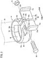
FIG. 3 is an outline overall perspective view of a stay, which constitutes part of the attachment part fixing structure for a vehicle; -
FIG. 4 is an enlarged rear view of principal parts when the stay is attached to the left front fork; -
FIG. 5 is a vertical cross-sectional view of principal parts when the stay is attached to the left front fork; -
FIG. 6 is a rear side perspective view of a reflector which is an attachment part for the vehicle; -
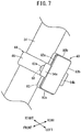
FIG. 7 is an outline perspective view of principal parts when the stay and the reflector are attached to the left front fork; and -
FIG. 8 is a rear perspective view of a reflector that constitutes part of an attachment part fixing structure for a vehicle according to another embodiment. - Preferred embodiments in relation to an attachment part fixing structure for a vehicle according to the present invention will be presented and described in detail below with reference to the accompanying drawings. In the present embodiment, the vehicle is exemplified by a scooter type motorcycle. Further, front and rear, up and down, and left and right directions are referred to based on the perspective of a rider who is seated on the motorcycle.
-
FIG. 1 is an outline side view of amotorcycle 10 to which an attachment part fixing structure for a vehicle according to an embodiment of the present invention is applied. Initially, an outline description concerning themotorcycle 10 will be presented. - The
motorcycle 10 is equipped with a vehicle body cover 12 that covers a vehicle body frame, afront wheel 14 that serves as a steered wheel, ahandle 16 for steering thefront wheel 14, arear wheel 18 which is a driven wheel, aseat 20 on which a rider sits, and aswing unit 22. - The
vehicle body cover 12 includes afront cover 24 that covers a front portion of the vehicle body frame, ahead cover 26 positioned above thefront cover 24, and arear cover 28 that covers a rear portion of the vehicle body frame. Ahead lamp 30 which irradiates light toward the front of the vehicle, aleft brake lever 32, and a non-illustrated right brake lever are provided on thehead cover 26. - The
front wheel 14 is connected to thehandle 16 via a leftfront fork 34 and a non-illustrated right front fork. Consequently, when the driver steers thehandle 16 to the left or right with respect to a direction of travel, thefront wheel 14 is inclined in a leftward or rightward direction. As a result, the travel direction of themotorcycle 10 is changed. - In this instance, a reflector (reflecting plate) 40 as a vehicle attachment part is positioned and fixed to the left
front fork 34. Next, a structure by which thereflector 40 is positioned and fixed to the leftfront fork 34, that is, the attachment part fixing structure according to the present embodiment, will be described. - The left
front fork 34 is a hollow columnar member having an annular shape with a substantially perfect circular cross section in a direction orthogonal to the longitudinal direction thereof. More specifically, the direction orthogonal to the longitudinal direction is a diametrical direction. Further, as shown inFIG. 2 , on a back surface that faces toward a side wall of the right front fork, aprotrusion 42 is provided, which protrudes outwardly in the diametrical direction and extends in the circumferential direction of the side wall. - The
stay 44 shown inFIG. 3 is attached to the leftfront fork 34. As will be discussed later, thereflector 40 is positioned on and fixed to the leftfront fork 34 through thestay 44. - The
stay 44 includes anannular member 46, fastenedportions surface support member 50, andclaw members annular member 46 is a substantially circular ring-shaped member having aninsertion hole 54 formed inside. Further, twowindow parts annular member 46. On an inner wall side of theannular member 46, arecess 58 is formed between both of thewindow parts recess 58 is formed is smaller than at other locations. As shown inFIGS. 4 and5 , when thestay 44 is attached to the leftfront fork 34, theprotrusion 42 enters into therecess 58. - A portion of the
annular member 46 is slightly cut out (seeFIG. 3 ) to thereby form a notch, and from such a cut out location, the fastenedportions front fork 34. The fastenedportions portions insertion grooves - Through
holes portions hole 62b of the fastenedportion 48b, ahexagonal hole 64, which is hexagonal in cross section and is wider than the throughhole 62b, communicates with the opening. Therefore, a step is formed at the boundary between the throughhole 62b and thehexagonal hole 64. A bolt 68 (fastening member) is passed through the throughholes bolt 68. Accompanying such screw-engagement, the fastenedportions hexagonal nut 70 enters into thehexagonal hole 64 and is seated on the step. - A wide back
surface support member 50 is joined to the fastenedportions surface support member 50 includes a frontside wall portion 72a that extends toward the front side of the vehicle from the fastenedportion 48a, and a rearside wall portion 72b that extends toward the rear side of the vehicle from the fastenedportion 48b. Since the fastenedportions side wall portion 72a and the rearside wall portion 72b. Theinsertion grooves - From rear end portions of the back
surface support member 50, theclaw members claw members portions surface support member 50 are folded back. Thereflector 40 is interposed in a vertically elongate manner (at an upright posture) between the backsurface support member 50 and the folded backportions FIG. 7 ). More specifically, the folded backportions reflector 40. Owing thereto, displacement of thereflector 40 in the vehicle transverse direction is suppressed. In this manner, the folded backportions reflector 40 in the vehicle transverse direction. - The
stay 44 which is constructed in the foregoing manner is preferably made from a resin. In this case, thestay 44 exhibits a large elasticity. - The
reflector 40 in this case, as shown inFIG. 6 , is of a rectangular shape having twoshort sides long sides reflector 40 is constituted by a non-illustrated plate shaped bracket and amain body 83. The non-illustrated plate shaped bracket is made of a resin reflective material and metal (for example, stainless steel) and is embedded in themain body 83 which is formed by insert molding. Acolumnar projection 84 is disposed on the plate shaped bracket, and thecolumnar projection 84 projects out on the back surface of themain body 83. A male screw 86 (engagement member) is engraved on a side wall of thecolumnar projection 84. Since thecolumnar projection 84 is made from metal, the rigidity of themale screw 86 is greater than that of thestay 44. - The attachment part fixing structure for a vehicle according to the present embodiment is constituted in the following manner by the
stay 44 and thereflector 40. - In a so-called preliminary state, the left
front fork 34 is inserted beforehand through theinsertion hole 54 of thestay 44. The leftfront fork 34 in this state is mounted on themotorcycle 10. Alternatively, the leftfront fork 34 may be inserted therein in a so-called retrofitted manner. In this case, for example, theclaw members portions stay 44 possesses sufficient elasticity as described above, the fastenedportions portions front fork 34 can easily be made to pass therethrough to theinsertion hole 54. - In either of such cases, the
protrusion 42 which is formed on the side wall of the leftfront fork 34 enters into therecess 58 formed on the back of theannular member 46 of thestay 44, and both members become engaged with each other. End portions in the circumferential direction of theprotrusion 42 engage with end portions in the circumferential direction of thewindow parts stay 44. As a result, the condition shown inFIGS. 4 and5 is brought about. - Furthermore, the columnar projection 84 (male screw 86) of the
reflector 40 is inserted into theinsertion grooves surface support member 50. Thereafter, if the fastenedportions portions reflector 40 is placed in abutment against the back surface support member 50 (the frontside wall portion 72a and the rearside wall portion 72b). In addition, together with thelong sides surface support member 50 and the folded backportions portions reflector 40. - Next, the
bolt 68 is inserted into the throughhole 62a of the fastenedportion 48a. A shank portion of thebolt 68 projects out from the throughhole 62b of the fastenedportion 48b. Thehexagonal nut 70 is screw-engaged with the projecting shank portion. Accompanying advancement of such screw-engagement, the fastenedportions annular member 46 presses against the side wall of the leftfront fork 34. - The
hexagonal nut 70 is seated on the step that forms the bottom surface of thehexagonal hole 64. Because the dimensions of thehexagonal hole 64 correspond with the dimensions of thehexagonal nut 70, rotation of thehexagonal nut 70 in thehexagonal hole 64 is prevented. This is because the apexes of thehexagonal nut 70 and thehexagonal hole 64 interfere with each other to prevent thehexagonal nut 70 from rotating. Stated otherwise, rotation of thehexagonal nut 70 is stopped. Therefore, it is unlikely that thehexagonal nut 70 will become loosened. - This feature, coupled with the fact that the
protrusion 42 provided on the leftfront fork 34 enters into therecess 58 on the inner wall of theannular member 46 and engages with therecess 58, enables thestay 44 to be firmly positioned and fixed to the leftfront fork 34. - More specifically, even if the
hexagonal nut 70 becomes loosened and the pressing force of theannular member 46 against the side wall of the leftfront fork 34 is reduced, when an external force that acts in the direction to rotate thestay 44 is applied, theprotrusion 42 formed on the leftfront fork 34 remains engaged with and latched by the end portions in the circumferential direction of thewindow parts stay 44 beyond its set position is prevented. Furthermore, since theprotrusion 42 enters into therecess 58 formed on the inner wall of theannular member 46, even if an external force acts in a direction to urge thestay 44 to ascend or descend along the leftfront fork 34, it is unlikely that theprotrusion 42 will be able to overcome and move beyond therecess 58 or thewindow parts stay 44 along the leftfront fork 34 is also prevented. - In this instance, accompanying the aforementioned tightening, the
columnar projection 84 of thereflector 40 is gripped firmly between each of the fastenedportions columnar projection 84, which is made from metal, is greater than the rigidity of thestay 44, which is made from resin. Therefore, the wall surfaces of theinsertion grooves portions stay 44 are deformed in shape in correspondence with the shape of themale screw 86. As a result, themale screw 86 becomes enmeshed with the wall surfaces of theinsertion grooves male screw 86 enmeshes with the fastenedportions portions reflector 40 will become detached from thestay 44. - In addition, because the
claw members FIG. 7 , thelong sides reflector 40 are gripped firmly between theclaw members reflector 40 attempts to rotate about themale screw 86, thelong sides claw members reflector 40 is prevented. More specifically, thereflector 40 is stopped from rotating by theclaw members reflector 40 in a direction of rotation thereof is restricted. - Further, since the folded back
portions reflector 40, thereflector 40 is blocked. Therefore, displacement of thecolumnar projection 84 of thereflector 40 outwardly in the vehicle transverse direction (left/right direction) from theinsertion grooves - In this manner, according to the present embodiment, it is unlikely for positional shifting of the
stay 44 itself to occur. In addition, by providing on the stay 44 a location where thereflector 40 is held, and further providing theclaw members reflector 40. Consequently, other people can visually confirm the reflected light from thereflector 40, whereby it is easy to recognize the existence of the vehicle. - In addition, the
male screw 86 of thecolumnar projection 84 of thereflector 40 becomes enmeshed with the wall surfaces of theinsertion grooves portions portions stay 44 abutting against the front surface of thereflector 40. In accordance with the above feature, it is unlikely that thereflector 40 will become detached or drop off from thestay 44. - Ultimately, by adopting the above-described configuration, without an increase in the number of component parts, positional shifting of the
stay 44 and thereflector 40 can be prevented, and it is possible to avoid falling off of thereflector 40 from thestay 44. - The present invention is not limited in particular to the above-described embodiment, and various modifications can be adopted therein without departing from the essence and gist of the present invention.
- For example, as shown in
FIG. 8 , acolumnar projection 90 having a polygonal shape (a square columnar shape inFIG. 8 ) may be provided. In this case, the shapes of theinsertion grooves portions columnar projection 90. - In such a condition, the apexes of the
columnar projection 90 coincide with the apexes of theinsertion grooves columnar projection 90 is prevented. As a result, rotation of thereflector 40 is stopped, and ultimately, positional shifting thereof is prevented. More specifically, in this state, the fastenedportions claw members stay 44. - Such a configuration is particularly effective when positioning and fixing a
reflector 92 having a substantially circular shape when viewed in plan. - Further, in the above embodiment, although an exemplary case has been presented in which the
reflectors stay 44, it goes without saying that the parts to be held may be parts other than thereflectors - Further, the vehicle may be a bicycle, a three wheeled vehicle, or the like, and the object to which the
stay 44 is attached is not limited to a leftfront fork 34, but may be any type of columnar member.
Claims (7)
- An attachment part fixing structure for a vehicle configured to position and fix a vehicle attachment part (40) to a side wall of a columnar member (34) of a vehicle (10), comprising:a stay (44) including an annular member (46) in which an insertion hole (54) is formed and through which the columnar member (34) is inserted, fastened portions (48a, 48b) that project outwardly of the side wall from the annular member (46) and face toward each other, and a back surface support member (50) that is joined to the fastened portions (48a, 48b) and supports a back surface of the vehicle attachment part (40); anda tightening member (68, 70) configured to tighten and fasten the fastened portions (48a, 48b) to thereby attach the stay (44) to the columnar member (34);wherein the stay (44) further includes a displacement regulating member (52a, 52b, 74a, 74b) configured to restrict displacement of the vehicle attachment part (40).
- The fixing structure according to claim 1, wherein the vehicle attachment part (40) includes on the back surface thereof a columnar projection (84) that projects toward the back surface support member (50), and the fastened portions (48a, 48b) grip the columnar projection (84) therebetween.
- The fixing structure according to claim 2, wherein the columnar projection (84) and the stay (44) are made from materials that differ in rigidity, and an engagement member (86) is provided on one from among the columnar projection (84) and the stay (44) that has a higher rigidity than the other.
- The fixing structure according to any one of claims 1 to 3, wherein the displacement regulating member (52a, 52b, 74a, 74b) is made up from claw members (52a, 52b) configured to grip at least portions of a peripheral edge part of the vehicle attachment part (40).
- The fixing structure according to any one of claims 1 to 3, wherein the fastened portions (48a, 48b) function simultaneously as the displacement regulating member.
- The fixing structure according to any one of claims 1 to 5, wherein a protrusion (42) is provided on the side wall of the columnar member (34), and a recess (58) into which the protrusion (42) enters is formed on the annular member (46).
- The fixing structure according to any one of claims 1 to 6, wherein the vehicle attachment part (40) is a reflector (40) configured to reflect light.
Applications Claiming Priority (1)
| Application Number | Priority Date | Filing Date | Title |
|---|---|---|---|
| JP2016061208A JP6412894B2 (en) | 2016-03-25 | 2016-03-25 | Mounting parts fixing structure for vehicles |
Publications (2)
| Publication Number | Publication Date |
|---|---|
| EP3222504A1 true EP3222504A1 (en) | 2017-09-27 |
| EP3222504B1 EP3222504B1 (en) | 2020-07-08 |
Family
ID=58428115
Family Applications (1)
| Application Number | Title | Priority Date | Filing Date |
|---|---|---|---|
| EP17162747.4A Active EP3222504B1 (en) | 2016-03-25 | 2017-03-24 | Attachment part fixing structure for vehicle |
Country Status (2)
| Country | Link |
|---|---|
| EP (1) | EP3222504B1 (en) |
| JP (1) | JP6412894B2 (en) |
Cited By (1)
| Publication number | Priority date | Publication date | Assignee | Title |
|---|---|---|---|---|
| CN112298441A (en) * | 2019-07-29 | 2021-02-02 | 株式会社岛野 | Operating equipment for human powered vehicles |
Citations (5)
| Publication number | Priority date | Publication date | Assignee | Title |
|---|---|---|---|---|
| FR549176A (en) * | 1922-03-21 | 1923-02-03 | Reflector refinements | |
| GB244679A (en) * | 1925-10-09 | 1925-12-24 | James Neale & Sons Ltd | Improvements in attachment clips |
| DE8903210U1 (en) * | 1989-03-15 | 1989-06-08 | Busch & Müller, 5882 Meinerzhagen | Reflectors for vehicles |
| JPH041088U (en) | 1990-04-18 | 1992-01-07 | ||
| DE20219756U1 (en) * | 2002-12-19 | 2003-06-26 | Büchel GmbH & Co., Fahrzeugteilefabrik KG, 36039 Fulda | Mounting for a reflector for use on a bicycle, the electrical reflector unit locates in a split circular bracket that has a clamping bolt |
Family Cites Families (14)
| Publication number | Priority date | Publication date | Assignee | Title |
|---|---|---|---|---|
| US3658408A (en) * | 1969-05-07 | 1972-04-25 | George A Santovi | Safety reflector device for vehicles |
| JPS6321363U (en) * | 1986-07-28 | 1988-02-12 | ||
| JPH03154871A (en) * | 1989-11-13 | 1991-07-02 | Nippon Seimitsu Sokki Kk | Speedometer for bicycle |
| JP2587000Y2 (en) * | 1992-09-10 | 1998-12-14 | 住友電装株式会社 | Battery terminal |
| JP2549173Y2 (en) * | 1993-06-18 | 1997-09-30 | ノートン自転車工業株式会社 | Auxiliary tool for mounting a bicycle running instrument |
| JP3218364B2 (en) * | 1995-06-20 | 2001-10-15 | 株式会社秀光 | Furniture component mounting bracket |
| JP3033026U (en) * | 1996-06-28 | 1997-01-17 | 株式会社あのびる | Horizontal piping installation device |
| JPH10113993A (en) * | 1996-10-11 | 1998-05-06 | T F T:Kk | Fixing jig for connecting pipe |
| JP3079175U (en) * | 2001-01-25 | 2001-08-10 | 雄二 篠原 | Mobile phone holder |
| US7448297B2 (en) * | 2004-08-04 | 2008-11-11 | Shimano (Singapore) Pte., Ltd | Mountable bicycle structure |
| JP5236232B2 (en) * | 2007-08-30 | 2013-07-17 | 本田技研工業株式会社 | Motorcycle light |
| JP2009085384A (en) * | 2007-10-01 | 2009-04-23 | Shigeki Nakamura | Pipe connector |
| JP2013043626A (en) * | 2011-08-22 | 2013-03-04 | Napolex Co | Vehicular portable device holder |
| JP6125918B2 (en) * | 2013-06-13 | 2017-05-10 | 株式会社ドクター中松創研 | Arm mobile terminal with easy screen operation |
-
2016
- 2016-03-25 JP JP2016061208A patent/JP6412894B2/en not_active Expired - Fee Related
-
2017
- 2017-03-24 EP EP17162747.4A patent/EP3222504B1/en active Active
Patent Citations (5)
| Publication number | Priority date | Publication date | Assignee | Title |
|---|---|---|---|---|
| FR549176A (en) * | 1922-03-21 | 1923-02-03 | Reflector refinements | |
| GB244679A (en) * | 1925-10-09 | 1925-12-24 | James Neale & Sons Ltd | Improvements in attachment clips |
| DE8903210U1 (en) * | 1989-03-15 | 1989-06-08 | Busch & Müller, 5882 Meinerzhagen | Reflectors for vehicles |
| JPH041088U (en) | 1990-04-18 | 1992-01-07 | ||
| DE20219756U1 (en) * | 2002-12-19 | 2003-06-26 | Büchel GmbH & Co., Fahrzeugteilefabrik KG, 36039 Fulda | Mounting for a reflector for use on a bicycle, the electrical reflector unit locates in a split circular bracket that has a clamping bolt |
Cited By (1)
| Publication number | Priority date | Publication date | Assignee | Title |
|---|---|---|---|---|
| CN112298441A (en) * | 2019-07-29 | 2021-02-02 | 株式会社岛野 | Operating equipment for human powered vehicles |
Also Published As
| Publication number | Publication date |
|---|---|
| JP6412894B2 (en) | 2018-10-24 |
| EP3222504B1 (en) | 2020-07-08 |
| JP2017171197A (en) | 2017-09-28 |
Similar Documents
| Publication | Publication Date | Title |
|---|---|---|
| JP5694854B2 (en) | Handle weight mounting structure for saddle-ride type vehicles | |
| JP5466969B2 (en) | Steering column device | |
| US11046352B2 (en) | Steering column | |
| US10494045B2 (en) | Reflector mounting structure for saddled vehicles | |
| JP2007099214A (en) | Child seat | |
| EP3222504B1 (en) | Attachment part fixing structure for vehicle | |
| US9944342B2 (en) | Straddle-type vehicle | |
| WO2014091640A1 (en) | Side mirror for straddled vehicle | |
| US9708021B2 (en) | Side stand of motorcycle | |
| JP2016060297A (en) | Steering device | |
| JP6709879B2 (en) | Fixed structure of fuel tank | |
| JP3726850B2 (en) | Mounting structure of resin parts in mold products | |
| CN107074314A (en) | Pedals for straddle vehicles | |
| JP7042721B2 (en) | Mounting structure of exterior members | |
| EP1746018B1 (en) | Saddle type vehicle | |
| JP4119450B2 (en) | Handle parts mounting structure | |
| JP4669873B2 (en) | Fastening device | |
| EP2103510B1 (en) | Bicycle accessory device | |
| JP6840244B2 (en) | License plate mounting part structure of saddle type vehicle | |
| GB2382551A (en) | Bicycle with rear wheel shock absorber | |
| US20190047474A1 (en) | Viewing device for vehicle | |
| JP4623108B2 (en) | Steering column holding structure | |
| JP5194752B2 (en) | Steering lock device | |
| JP2009196571A (en) | Mudguard mounting device for bicycle | |
| JP6699781B2 (en) | Steering device |
Legal Events
| Date | Code | Title | Description |
|---|---|---|---|
| PUAI | Public reference made under article 153(3) epc to a published international application that has entered the european phase |
Free format text: ORIGINAL CODE: 0009012 |
|
| STAA | Information on the status of an ep patent application or granted ep patent |
Free format text: STATUS: REQUEST FOR EXAMINATION WAS MADE |
|
| 17P | Request for examination filed |
Effective date: 20170324 |
|
| AK | Designated contracting states |
Kind code of ref document: A1 Designated state(s): AL AT BE BG CH CY CZ DE DK EE ES FI FR GB GR HR HU IE IS IT LI LT LU LV MC MK MT NL NO PL PT RO RS SE SI SK SM TR |
|
| AX | Request for extension of the european patent |
Extension state: BA ME |
|
| GRAP | Despatch of communication of intention to grant a patent |
Free format text: ORIGINAL CODE: EPIDOSNIGR1 |
|
| STAA | Information on the status of an ep patent application or granted ep patent |
Free format text: STATUS: GRANT OF PATENT IS INTENDED |
|
| INTG | Intention to grant announced |
Effective date: 20200206 |
|
| GRAS | Grant fee paid |
Free format text: ORIGINAL CODE: EPIDOSNIGR3 |
|
| GRAA | (expected) grant |
Free format text: ORIGINAL CODE: 0009210 |
|
| STAA | Information on the status of an ep patent application or granted ep patent |
Free format text: STATUS: THE PATENT HAS BEEN GRANTED |
|
| GRAL | Information related to payment of fee for publishing/printing deleted |
Free format text: ORIGINAL CODE: EPIDOSDIGR3 |
|
| GRAS | Grant fee paid |
Free format text: ORIGINAL CODE: EPIDOSNIGR3 |
|
| AK | Designated contracting states |
Kind code of ref document: B1 Designated state(s): AL AT BE BG CH CY CZ DE DK EE ES FI FR GB GR HR HU IE IS IT LI LT LU LV MC MK MT NL NO PL PT RO RS SE SI SK SM TR |
|
| REG | Reference to a national code |
Ref country code: CH Ref legal event code: EP Ref country code: AT Ref legal event code: REF Ref document number: 1288160 Country of ref document: AT Kind code of ref document: T Effective date: 20200715 |
|
| REG | Reference to a national code |
Ref country code: DE Ref legal event code: R096 Ref document number: 602017019217 Country of ref document: DE |
|
| REG | Reference to a national code |
Ref country code: IE Ref legal event code: FG4D |
|
| REG | Reference to a national code |
Ref country code: LT Ref legal event code: MG4D |
|
| REG | Reference to a national code |
Ref country code: AT Ref legal event code: MK05 Ref document number: 1288160 Country of ref document: AT Kind code of ref document: T Effective date: 20200708 |
|
| REG | Reference to a national code |
Ref country code: NL Ref legal event code: MP Effective date: 20200708 |
|
| PG25 | Lapsed in a contracting state [announced via postgrant information from national office to epo] |
Ref country code: FI Free format text: LAPSE BECAUSE OF FAILURE TO SUBMIT A TRANSLATION OF THE DESCRIPTION OR TO PAY THE FEE WITHIN THE PRESCRIBED TIME-LIMIT Effective date: 20200708 Ref country code: NO Free format text: LAPSE BECAUSE OF FAILURE TO SUBMIT A TRANSLATION OF THE DESCRIPTION OR TO PAY THE FEE WITHIN THE PRESCRIBED TIME-LIMIT Effective date: 20201008 Ref country code: GR Free format text: LAPSE BECAUSE OF FAILURE TO SUBMIT A TRANSLATION OF THE DESCRIPTION OR TO PAY THE FEE WITHIN THE PRESCRIBED TIME-LIMIT Effective date: 20201009 Ref country code: PT Free format text: LAPSE BECAUSE OF FAILURE TO SUBMIT A TRANSLATION OF THE DESCRIPTION OR TO PAY THE FEE WITHIN THE PRESCRIBED TIME-LIMIT Effective date: 20201109 Ref country code: AT Free format text: LAPSE BECAUSE OF FAILURE TO SUBMIT A TRANSLATION OF THE DESCRIPTION OR TO PAY THE FEE WITHIN THE PRESCRIBED TIME-LIMIT Effective date: 20200708 Ref country code: HR Free format text: LAPSE BECAUSE OF FAILURE TO SUBMIT A TRANSLATION OF THE DESCRIPTION OR TO PAY THE FEE WITHIN THE PRESCRIBED TIME-LIMIT Effective date: 20200708 Ref country code: SE Free format text: LAPSE BECAUSE OF FAILURE TO SUBMIT A TRANSLATION OF THE DESCRIPTION OR TO PAY THE FEE WITHIN THE PRESCRIBED TIME-LIMIT Effective date: 20200708 Ref country code: BG Free format text: LAPSE BECAUSE OF FAILURE TO SUBMIT A TRANSLATION OF THE DESCRIPTION OR TO PAY THE FEE WITHIN THE PRESCRIBED TIME-LIMIT Effective date: 20201008 Ref country code: ES Free format text: LAPSE BECAUSE OF FAILURE TO SUBMIT A TRANSLATION OF THE DESCRIPTION OR TO PAY THE FEE WITHIN THE PRESCRIBED TIME-LIMIT Effective date: 20200708 Ref country code: LT Free format text: LAPSE BECAUSE OF FAILURE TO SUBMIT A TRANSLATION OF THE DESCRIPTION OR TO PAY THE FEE WITHIN THE PRESCRIBED TIME-LIMIT Effective date: 20200708 |
|
| PG25 | Lapsed in a contracting state [announced via postgrant information from national office to epo] |
Ref country code: PL Free format text: LAPSE BECAUSE OF FAILURE TO SUBMIT A TRANSLATION OF THE DESCRIPTION OR TO PAY THE FEE WITHIN THE PRESCRIBED TIME-LIMIT Effective date: 20200708 Ref country code: LV Free format text: LAPSE BECAUSE OF FAILURE TO SUBMIT A TRANSLATION OF THE DESCRIPTION OR TO PAY THE FEE WITHIN THE PRESCRIBED TIME-LIMIT Effective date: 20200708 Ref country code: RS Free format text: LAPSE BECAUSE OF FAILURE TO SUBMIT A TRANSLATION OF THE DESCRIPTION OR TO PAY THE FEE WITHIN THE PRESCRIBED TIME-LIMIT Effective date: 20200708 Ref country code: IS Free format text: LAPSE BECAUSE OF FAILURE TO SUBMIT A TRANSLATION OF THE DESCRIPTION OR TO PAY THE FEE WITHIN THE PRESCRIBED TIME-LIMIT Effective date: 20201108 |
|
| PG25 | Lapsed in a contracting state [announced via postgrant information from national office to epo] |
Ref country code: NL Free format text: LAPSE BECAUSE OF FAILURE TO SUBMIT A TRANSLATION OF THE DESCRIPTION OR TO PAY THE FEE WITHIN THE PRESCRIBED TIME-LIMIT Effective date: 20200708 |
|
| REG | Reference to a national code |
Ref country code: DE Ref legal event code: R097 Ref document number: 602017019217 Country of ref document: DE |
|
| PG25 | Lapsed in a contracting state [announced via postgrant information from national office to epo] |
Ref country code: EE Free format text: LAPSE BECAUSE OF FAILURE TO SUBMIT A TRANSLATION OF THE DESCRIPTION OR TO PAY THE FEE WITHIN THE PRESCRIBED TIME-LIMIT Effective date: 20200708 Ref country code: SM Free format text: LAPSE BECAUSE OF FAILURE TO SUBMIT A TRANSLATION OF THE DESCRIPTION OR TO PAY THE FEE WITHIN THE PRESCRIBED TIME-LIMIT Effective date: 20200708 Ref country code: RO Free format text: LAPSE BECAUSE OF FAILURE TO SUBMIT A TRANSLATION OF THE DESCRIPTION OR TO PAY THE FEE WITHIN THE PRESCRIBED TIME-LIMIT Effective date: 20200708 Ref country code: DK Free format text: LAPSE BECAUSE OF FAILURE TO SUBMIT A TRANSLATION OF THE DESCRIPTION OR TO PAY THE FEE WITHIN THE PRESCRIBED TIME-LIMIT Effective date: 20200708 Ref country code: CZ Free format text: LAPSE BECAUSE OF FAILURE TO SUBMIT A TRANSLATION OF THE DESCRIPTION OR TO PAY THE FEE WITHIN THE PRESCRIBED TIME-LIMIT Effective date: 20200708 |
|
| PLBE | No opposition filed within time limit |
Free format text: ORIGINAL CODE: 0009261 |
|
| STAA | Information on the status of an ep patent application or granted ep patent |
Free format text: STATUS: NO OPPOSITION FILED WITHIN TIME LIMIT |
|
| PG25 | Lapsed in a contracting state [announced via postgrant information from national office to epo] |
Ref country code: AL Free format text: LAPSE BECAUSE OF FAILURE TO SUBMIT A TRANSLATION OF THE DESCRIPTION OR TO PAY THE FEE WITHIN THE PRESCRIBED TIME-LIMIT Effective date: 20200708 |
|
| 26N | No opposition filed |
Effective date: 20210409 |
|
| PG25 | Lapsed in a contracting state [announced via postgrant information from national office to epo] |
Ref country code: SK Free format text: LAPSE BECAUSE OF FAILURE TO SUBMIT A TRANSLATION OF THE DESCRIPTION OR TO PAY THE FEE WITHIN THE PRESCRIBED TIME-LIMIT Effective date: 20200708 |
|
| PG25 | Lapsed in a contracting state [announced via postgrant information from national office to epo] |
Ref country code: SI Free format text: LAPSE BECAUSE OF FAILURE TO SUBMIT A TRANSLATION OF THE DESCRIPTION OR TO PAY THE FEE WITHIN THE PRESCRIBED TIME-LIMIT Effective date: 20200708 |
|
| REG | Reference to a national code |
Ref country code: DE Ref legal event code: R119 Ref document number: 602017019217 Country of ref document: DE |
|
| PG25 | Lapsed in a contracting state [announced via postgrant information from national office to epo] |
Ref country code: MC Free format text: LAPSE BECAUSE OF FAILURE TO SUBMIT A TRANSLATION OF THE DESCRIPTION OR TO PAY THE FEE WITHIN THE PRESCRIBED TIME-LIMIT Effective date: 20200708 |
|
| REG | Reference to a national code |
Ref country code: CH Ref legal event code: PL |
|
| GBPC | Gb: european patent ceased through non-payment of renewal fee |
Effective date: 20210324 |
|
| REG | Reference to a national code |
Ref country code: BE Ref legal event code: MM Effective date: 20210331 |
|
| PG25 | Lapsed in a contracting state [announced via postgrant information from national office to epo] |
Ref country code: LI Free format text: LAPSE BECAUSE OF NON-PAYMENT OF DUE FEES Effective date: 20210331 Ref country code: LU Free format text: LAPSE BECAUSE OF NON-PAYMENT OF DUE FEES Effective date: 20210324 Ref country code: DE Free format text: LAPSE BECAUSE OF NON-PAYMENT OF DUE FEES Effective date: 20211001 Ref country code: CH Free format text: LAPSE BECAUSE OF NON-PAYMENT OF DUE FEES Effective date: 20210331 Ref country code: FR Free format text: LAPSE BECAUSE OF NON-PAYMENT OF DUE FEES Effective date: 20210331 Ref country code: GB Free format text: LAPSE BECAUSE OF NON-PAYMENT OF DUE FEES Effective date: 20210324 Ref country code: IE Free format text: LAPSE BECAUSE OF NON-PAYMENT OF DUE FEES Effective date: 20210324 |
|
| PG25 | Lapsed in a contracting state [announced via postgrant information from national office to epo] |
Ref country code: BE Free format text: LAPSE BECAUSE OF NON-PAYMENT OF DUE FEES Effective date: 20210331 |
|
| PG25 | Lapsed in a contracting state [announced via postgrant information from national office to epo] |
Ref country code: HU Free format text: LAPSE BECAUSE OF FAILURE TO SUBMIT A TRANSLATION OF THE DESCRIPTION OR TO PAY THE FEE WITHIN THE PRESCRIBED TIME-LIMIT; INVALID AB INITIO Effective date: 20170324 |
|
| PG25 | Lapsed in a contracting state [announced via postgrant information from national office to epo] |
Ref country code: CY Free format text: LAPSE BECAUSE OF FAILURE TO SUBMIT A TRANSLATION OF THE DESCRIPTION OR TO PAY THE FEE WITHIN THE PRESCRIBED TIME-LIMIT Effective date: 20200708 |
|
| PG25 | Lapsed in a contracting state [announced via postgrant information from national office to epo] |
Ref country code: MK Free format text: LAPSE BECAUSE OF FAILURE TO SUBMIT A TRANSLATION OF THE DESCRIPTION OR TO PAY THE FEE WITHIN THE PRESCRIBED TIME-LIMIT Effective date: 20200708 |
|
| PG25 | Lapsed in a contracting state [announced via postgrant information from national office to epo] |
Ref country code: MT Free format text: LAPSE BECAUSE OF FAILURE TO SUBMIT A TRANSLATION OF THE DESCRIPTION OR TO PAY THE FEE WITHIN THE PRESCRIBED TIME-LIMIT Effective date: 20200708 |
|
| PG25 | Lapsed in a contracting state [announced via postgrant information from national office to epo] |
Ref country code: TR Free format text: LAPSE BECAUSE OF FAILURE TO SUBMIT A TRANSLATION OF THE DESCRIPTION OR TO PAY THE FEE WITHIN THE PRESCRIBED TIME-LIMIT Effective date: 20200708 |
|
| PGFP | Annual fee paid to national office [announced via postgrant information from national office to epo] |
Ref country code: IT Payment date: 20260219 Year of fee payment: 10 |