EP3222448A1 - Dispositif de distribution d'air pour tourelle - Google Patents
Dispositif de distribution d'air pour tourelle Download PDFInfo
- Publication number
- EP3222448A1 EP3222448A1 EP17160726.0A EP17160726A EP3222448A1 EP 3222448 A1 EP3222448 A1 EP 3222448A1 EP 17160726 A EP17160726 A EP 17160726A EP 3222448 A1 EP3222448 A1 EP 3222448A1
- Authority
- EP
- European Patent Office
- Prior art keywords
- sheath
- duct
- turret
- air
- distribution device
- Prior art date
- Legal status (The legal status is an assumption and is not a legal conclusion. Google has not performed a legal analysis and makes no representation as to the accuracy of the status listed.)
- Granted
Links
Images


Classifications
-
- H—ELECTRICITY
- H01—ELECTRIC ELEMENTS
- H01F—MAGNETS; INDUCTANCES; TRANSFORMERS; SELECTION OF MATERIALS FOR THEIR MAGNETIC PROPERTIES
- H01F27/00—Details of transformers or inductances, in general
- H01F27/02—Casings
-
- B—PERFORMING OPERATIONS; TRANSPORTING
- B60—VEHICLES IN GENERAL
- B60H—ARRANGEMENTS OF HEATING, COOLING, VENTILATING OR OTHER AIR-TREATING DEVICES SPECIALLY ADAPTED FOR PASSENGER OR GOODS SPACES OF VEHICLES
- B60H1/00—Heating, cooling or ventilating devices
- B60H1/00007—Combined heating, ventilating, or cooling devices
- B60H1/00021—Air flow details of HVAC devices
- B60H1/00028—Constructional lay-out of the devices in the vehicle
-
- B—PERFORMING OPERATIONS; TRANSPORTING
- B60—VEHICLES IN GENERAL
- B60H—ARRANGEMENTS OF HEATING, COOLING, VENTILATING OR OTHER AIR-TREATING DEVICES SPECIALLY ADAPTED FOR PASSENGER OR GOODS SPACES OF VEHICLES
- B60H1/00—Heating, cooling or ventilating devices
- B60H1/00357—Air-conditioning arrangements specially adapted for particular vehicles
- B60H1/00414—Air-conditioning arrangements specially adapted for particular vehicles for military, emergency, safety or security vehicles
-
- B—PERFORMING OPERATIONS; TRANSPORTING
- B60—VEHICLES IN GENERAL
- B60H—ARRANGEMENTS OF HEATING, COOLING, VENTILATING OR OTHER AIR-TREATING DEVICES SPECIALLY ADAPTED FOR PASSENGER OR GOODS SPACES OF VEHICLES
- B60H1/00—Heating, cooling or ventilating devices
- B60H1/00507—Details, e.g. mounting arrangements, desaeration devices
- B60H1/00557—Details of ducts or cables
- B60H1/00564—Details of ducts or cables of air ducts
-
- F—MECHANICAL ENGINEERING; LIGHTING; HEATING; WEAPONS; BLASTING
- F41—WEAPONS
- F41H—ARMOUR; ARMOURED TURRETS; ARMOURED OR ARMED VEHICLES; MEANS OF ATTACK OR DEFENCE, e.g. CAMOUFLAGE, IN GENERAL
- F41H5/00—Armour; Armour plates
- F41H5/20—Turrets
-
- F—MECHANICAL ENGINEERING; LIGHTING; HEATING; WEAPONS; BLASTING
- F41—WEAPONS
- F41H—ARMOUR; ARMOURED TURRETS; ARMOURED OR ARMED VEHICLES; MEANS OF ATTACK OR DEFENCE, e.g. CAMOUFLAGE, IN GENERAL
- F41H7/00—Armoured or armed vehicles
- F41H7/02—Land vehicles with enclosing armour, e.g. tanks
- F41H7/03—Air-pressurised compartments for crew; Means for preventing admission of noxious substances, e.g. combustion gas from gun barrels, in crew compartments; Sealing arrangements
-
- H—ELECTRICITY
- H01—ELECTRIC ELEMENTS
- H01F—MAGNETS; INDUCTANCES; TRANSFORMERS; SELECTION OF MATERIALS FOR THEIR MAGNETIC PROPERTIES
- H01F27/00—Details of transformers or inductances, in general
- H01F27/24—Magnetic cores
- H01F27/26—Fastening parts of the core together; Fastening or mounting the core on casing or support
- H01F27/263—Fastening parts of the core together
-
- H—ELECTRICITY
- H01—ELECTRIC ELEMENTS
- H01F—MAGNETS; INDUCTANCES; TRANSFORMERS; SELECTION OF MATERIALS FOR THEIR MAGNETIC PROPERTIES
- H01F27/00—Details of transformers or inductances, in general
- H01F27/24—Magnetic cores
- H01F27/26—Fastening parts of the core together; Fastening or mounting the core on casing or support
- H01F27/266—Fastening or mounting the core on casing or support
-
- H—ELECTRICITY
- H01—ELECTRIC ELEMENTS
- H01F—MAGNETS; INDUCTANCES; TRANSFORMERS; SELECTION OF MATERIALS FOR THEIR MAGNETIC PROPERTIES
- H01F30/00—Fixed transformers not covered by group H01F19/00
- H01F30/06—Fixed transformers not covered by group H01F19/00 characterised by the structure
- H01F30/10—Single-phase transformers
Definitions
- the technical field of the invention is that of air conditioning air distribution devices for military vehicles comprising a turret.
- the turret comprises a pair of coaxial circular ducts intended, for one to convey fresh air, and for the other to discharge hot air or conversely according to the desired temperature conditions in turret.
- the sheaths are generally disposed in the vicinity of the joint plane between the turret and the vehicle body and in the vicinity of the turret circular.
- the presence of ducts in this area of the vehicle and their volume is troublesome to allow the passage of a chassis operator to the turret or for maintenance operations. In general, ducts can hinder accessibility in their neighborhood.
- the invention proposes to solve this problem of accessibility and passage by providing means for temporarily breaking the continuity of the ducts to provide a passage between them.
- the subject of the invention is an air conditioning air distribution device for a turret of a vehicle mounted rotatably with respect to a vehicle body, a device comprising at least one air duct sheath, a duct comprising a chute. solidarisable to the vehicle and a shutter securable to the turret, sheath comprising at least a first and a second air flow orifice, characterized in that the sheath is in the form of an arc of a circle coaxial with the axis of rotation of the turret, and in that it comprises at least one arc-shaped conduit having the same average radius as that of the sheath and slidable relative to the sheath between a closed position where the conduit joins one end of the sheath to another end of said sheath, or another sheath, for a continuity of air circulation between the sheaths, and an open position in which the conduit is slid inside the sheath so as to leave a transverse passage to the sheath according to
- the conduit comprises a bottom having an annular sector opening coaxial with the sheath, bottom covered by a lid, bottom and cover adapted to rotate relative to each other about the axis of rotation of the turret.
- the correspondence of profiles of the inner section of the sheath with the profile of the outer section of the duct provides a guide in rotation of the duct relative to the sheath.
- the bottom of the conduit comprises a locking means in position which cooperates with a portion of the chute.
- the conduit comprises a locking means in the position of the cover which cooperates with a part of the shutter.
- the device comprises two ducts and two ducts which in the closed position join each end of the ducts and which emit two transverse passages to the ducts in the open position.
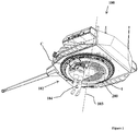
- a turret 100 of a military vehicle has an opening 102 circular at its lower part and which is centered on an axis 103 of vertical pivoting of the turret 100 relative to a vehicle body (vehicle and vehicle body not shown).
- This opening 102 is intended inter alia for the passage of an operator 104 between the vehicle body and the turret 100 for maintenance operations.
- the vehicle is equipped with an air conditioning air distribution device 1 as described in the patent FR3014372 .
- This device 1 is coaxial with the opening 102 and comprises at least one circular air-gap sheath 200 for conveying fresh air from the body to the turret 100. It is shown in FIG. figure 1 a circled area C which makes it possible to locate and highlight an interference between the air distribution device 1 and the operator 104.
- a device 1 according to the invention comprises a sheath 1a in a circular arc centered on the pivot axis 103 of the turret.
- This sheath 1a comprises a first orifice 10 and a second air flow orifice 11 respectively intended to allow the entry of fresh air from the chassis and to conduct this fresh air into the turret.
- this sheath 1a is not closed on itself but has an interruption of its continuity thus creating two ends 2a and 2b to the sheath 1a.
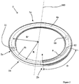
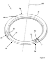
- the device 1 can adopt a position called closed position illustrated in FIGS. figures 2 and 3 and a so-called open position illustrated to figure 4 and 5 .
- a conduit 1b in the shape of an arc of a circle complementary to that of the sheath 1a connects each end 2a and 2b of the sheath 1a, thereby ensuring continuity of air flow between the sheath 1a and the conduit 1b and therefore also within the device 1.
- the duct 1b is able to slide telescopically in the sheath 1a to give an open position to the ventilation duct 1 according to the invention.
- the arc of the circle of the duct 1b has the same mean radius R as that R 'of the sheath 1a (radii represented figure 2 ), and the conduit 1b can slide integrally to one of the ends 2a or 2b of the sheath 1a until retracting completely in the sheath 1a.
- Mean radius means the radius of the circle disposed equidistant from the side walls of the sheath or duct.
- a passage P can then be arranged transversely to the device 1 which allows an operator 104 according to the figure 7 to be able to evolve in the vicinity of the sheath 1a without interfering with the device 1.
- the sheath 1a comprises a chute 3a which has an annular sector-shaped opening centered on the axis of rotation 103, which opening is covered by a shutter 4a.
- the conduit 1b has a bottom 3b which has an annular sector-shaped opening centered on the axis of rotation 103 and which is covered by a cover 4b.
- the chute 3a has two flanges 5 which each delimit a circular slot 23.
- the sheath 1a thus has such a slot 23 on its side intended to be oriented towards the turret pivot axis and on the opposite side intended to be oriented towards the outside of the turret.
- Each slot 23 is intended to receive a fin 6 disposed on each side of the shutter 4a.
- the shutter 4a is guided in rotation about the turret axis 103 and can rotate relative to the chute 3a.
- the conduit 1b is shaped with a profile of its outer section in correspondence with the internal profile of the section of the sheath 1a. In this way it is easy to slide the conduit 1b in the sheath 1a. In addition, this shape matching limits air leakage at the joints of the sheaths 1a and 1b.
- the cover 4b is rotatable relative to the bottom 3b but also with respect to the chute 3a.
- a border 20 on each side of the cover 4b allows the cover 4b to bear on the sides of the bottom 3b.
- the device 1 comprises a first 7 and a second 8 securing means respectively for securing the chute 3a with the bottom 3b for one, and the shutter 4a with the lid 4b for the other.
- the bottom 3b of the conduit 1b is integral with the chute 3a of the sheath 1a and the cover 4b of the conduit 1b is integral with the shutter 4a of the sheath.
- the cover 4b and the shutter 4a which are integral with the turret, pivot together with the bottom 3b and the chute 3a which are integral with the vehicle.
- the turret will be stopped in a position to position the lid 4b just above the bottom 3b. It is then possible to separate these two elements, by unscrewing the first 7 and second 8 securing means, to be able to slide the two parts of the conduit 1b in the sheath 1a and release the passage P.
- the first fastening means 7 visible to the figure 3 for example, a knurled screw 7 conventionally known to those skilled in the art of solid bottom 3b and able to flow in an oblong hole arc 7a of the chute 3a and one end of which opens at the first end 2a of the chute 3a.
- the securing means 7 presses the chute 3a against the bottom 3b thus blocking the bottom 3b in the closed position relative to the chute 3a.
- the second end 2b of the chute 3a also has an oblong hole 7b which makes it possible to block the bottom 3b in the open position.
- the second securing means 8 also comprises, for example, a knurled screw 8 intended to pressurize one face of the shutter 4a on a corresponding face of the cover 4b in order to immobilize them relative to each other.
- This second securing means 8 makes it possible to block the cover 4b in the open position or in the closed position relative to the shutter 4a, but it also allows intermediate opening adjustments thanks to an oblong hole 9 situated on the shutter 4a.
- oblong hole 9 traversing an angular sector of length at least equivalent to the length of the opening between the ends 2a and 2b of the sheath 1a.
- the skilled person will take care to position the second knurled screw 8 at a distance D from the first end 12 of the cover 4b at least equal to one time the length of the oblong hole 9 as represented at figure 2 .
- the flow of air can be done without discontinuity in the entire sheath 1 and for all orientations in the bearing of the turret.
- the turret When turret accessibility is desired, the turret is put into a predetermined bearing position that matches the shutter 4a above the chute 3a and the lid 4b over the background 3b.
- the bottom 3b and the cover 4b forming the conduit 1b can then be slid into the sheath 1a to obtain an open position of the device 1 and thus leave open access to the turret for an operator.
- the device according to the invention may comprise a plurality of sheaths 1a and a plurality of ducts 1b.
- the device 1 shown in figure 9 comprises two sheaths 1a interconnected by two ducts 1b which can slide in the sheaths 1a in order to clear two passage zones P.
- FIG. 9 represents in dotted lines a second device 22 surrounding the first device 1 and whose passage zones P correspond.
Landscapes
- Engineering & Computer Science (AREA)
- Power Engineering (AREA)
- Physics & Mathematics (AREA)
- Thermal Sciences (AREA)
- Mechanical Engineering (AREA)
- General Engineering & Computer Science (AREA)
- Air-Conditioning For Vehicles (AREA)
- Air-Flow Control Members (AREA)
- Duct Arrangements (AREA)
Abstract
Description
- Le domaine technique de l'invention est celui des dispositifs de distribution d'air de climatisation pour véhicules militaires comportant une tourelle.
- Afin de climatiser une tourelle de char, il est connu de la demande de brevet
FR3014372 - Pour cela, la tourelle comporte une paire de gaines circulaires coaxiales destinées, pour l'une à acheminer de l'air frais, et pour l'autre à évacuer de l'air chaud ou inversement selon les conditions de température souhaitées en tourelle. Les gaines sont en général disposées au voisinage du plan de jointure entre la tourelle et la caisse du véhicule et au voisinage de la circulaire de tourelle. La présence des gaines dans cette zone du véhicule ainsi que leur volume est gênant pour permettre le passage d'un opérateur du châssis vers la tourelle ou pour les opérations de maintenance. De manière générale, les gaines peuvent gêner l'accessibilité dans leur voisinage.
- L'invention propose de résoudre ce problème d'accessibilité et de passage en fournissant des moyens de rupture temporaire de la continuité des gaines afin de ménager un passage entre celles-ci.
- Ainsi, l'invention a pour objet un dispositif de distribution d'air de climatisation pour une tourelle d'un véhicule montée rotative par rapport à une caisse du véhicule, dispositif comportant au moins une gaine de conduite d'air, gaine comportant une goulotte solidarisable au véhicule et un obturateur solidarisable à la tourelle, gaine comportant au moins un premier et un second orifice d'écoulement d'air, dispositif caractérisé en ce que la gaine est en forme d'arc de cercle coaxial à l'axe de rotation de la tourelle, et en ce qu' il comprend au moins un conduit en forme d'arc de cercle ayant le même rayon moyen que celui de la gaine et apte à coulisser relativement à la gaine entre une position fermée où le conduit joint une extrémité de la gaine à une autre extrémité de ladite gaine, ou d'une autre gaine, pour une continuité de circulation de l'air entre les gaines, et une position ouverte dans laquelle le conduit est coulissé à l'intérieur de la gaine de manière à laisser un passage transversal à la gaine selon un secteur circulaire.
- Avantageusement, le conduit comporte un fond comportant une ouverture en secteur annulaire coaxial à la gaine, fond recouvert par un couvercle, fond et couvercle aptes à tourner l'un par rapport à l'autre autour de l'axe de rotation de la tourelle.
- Avantageusement, la correspondance de profils de la section interne de la gaine avec le profil de la section externe du conduit assure un guidage en rotation du conduit par rapport à la gaine.
- Avantageusement, le fond du conduit comporte un moyen de blocage en position qui coopère avec une partie de la goulotte.
- Avantageusement, le conduit comporte un moyen de blocage en position du couvercle qui coopère avec une partie de l'obturateur.
- Avantageusement, le dispositif comporte deux gaines et deux conduits qui en position fermée rejoignent chacune des extrémités des gaines et qui dégagent deux passages transversaux aux gaines en position ouverte.
- L'invention sera mieux comprise à la lecture de la description suivante, description faite en référence aux dessins en annexe, dessins dans lesquels :
- La
figure 1 représente une vue partielle de trois quarts en contre plongée de la partie inférieure d'une tourelle comportant un dispositif selon l'invention en interférence avec un opérateur. - La
figure 2 représente une vue de trois quarts de dessus d'un dispositif selon l'invention en position fermée. - La
figure 3 représente une vue de trois quarts de dessous d'un dispositif selon l'invention en position fermée. - La
figure 4 représente une vue de trois quarts de dessus d'un dispositif selon l'invention en position ouverte. - La
figure 5 représente une vue de trois quarts de dessous d'un dispositif selon l'invention en position ouverte. - La
figure 6 représente une vue partielle de détail en coupe transversale selon le plan PP de lafigure 4 d'un dispositif selon l'invention. - La
figure 7 représente une vue partielle de trois quarts en contre plongée de la partie inférieure d'une tourelle comportant un dispositif selon l'invention sans interférence avec un opérateur. - La
figure 8 représente une vue schématique en coupe transversale selon le plan PP de lafigure 4 . - La
figure 9 représente une vue schématique de dessus d'un autre mode de réalisation de l'invention. - Selon la
figure 1 , une tourelle 100 d'un véhicule militaire comporte une ouverture 102 circulaire à sa partie inférieure et qui est centrée sur un axe 103 de pivotement vertical de la tourelle 100 par rapport à une caisse du véhicule (véhicule et caisse du véhicule non représentés). - Cette ouverture 102 est destinée entre autre au passage d'un opérateur 104 entre la caisse du véhicule et la tourelle 100 pour des opérations de maintenance.
- Le véhicule est équipé d'un dispositif 1 de distribution d'air de climatisation tel que décrit dans le brevet
FR3014372 figure 1 une zone encerclée C qui permet de localiser et mettre en évidence une interférence entre le dispositif de distribution d'air 1 et l'opérateur 104. - Selon les
figures 2 et3 , un dispositif 1 selon l'invention comporte une gaine 1a en arc de cercle centrée sur l'axe 103 de pivotement de la tourelle. Cette gaine 1a comporte un premier orifice 10 et un second orifice 11 d'écoulement d'air respectivement destinés à permettre l'entrée d'air frais depuis le châssis et à conduire cet air frais dans la tourelle. - Contrairement à la gaine 200 de l'état de la technique, cette gaine 1a n'est pas close sur elle-même mais présente une interruption de sa continuité créant ainsi deux extrémités 2a et 2b à la gaine 1a.
- Le dispositif 1 peut adopter une position dite position fermée illustrée aux
figures 2 et3 et une position dite ouverte illustrée auxfigure 4 et5 . Dans la position fermée un conduit 1b en forme d'arc de cercle complémentaire à celui de la gaine 1a, relie chaque extrémité 2a et 2b de la gaine 1a, assurant ainsi une continuité de circulation de l'air entre la gaine 1a et le conduit 1b et donc aussi au sein du dispositif 1. - Comme visible aux
figures 4 ,5 et6 , le conduit 1b est apte à coulisser de manière télescopique dans la gaine 1a pour donner une position ouverte à la gaine aéraulique 1 selon l'invention. A cette fin l'arc de cercle du conduit 1b a le même rayon moyen R que celui R' de la gaine 1a (rayons représentésfigure 2 ), ainsi le conduit 1b peut coulisser intégralement vers une des extrémités 2a ou 2b de la gaine 1a jusqu'à s'escamoter totalement dans la gaine 1a. On entend par rayon moyen le rayon du cercle disposé à égale distance des parois latérales de la gaine ou du conduit. - Un passage P peut alors être aménagé transversalement au dispositif 1 ce qui permet à un opérateur 104 selon la
figure 7 de pouvoir évoluer au voisinage de la gaine 1a sans interférer avec le dispositif 1. - Comme visible aux
figures 2 à 6 , la gaine 1a comporte une goulotte 3a qui a une ouverture en forme de secteur annulaire centré sur l'axe de rotation 103, ouverture qui est couverte par un obturateur 4a. De même, le conduit 1b comporte un fond 3b qui a une ouverture en forme de secteur annulaire centré sur l'axe de rotation 103 et qui est couverte par un couvercle 4b. - On notera à la
figure 4 et auxfigures 6 et8 que la goulotte 3a comporte deux rebords 5 qui délimitent chacun une fente circulaire 23. La gaine 1a comporte ainsi une telle fente 23 sur son coté destiné à être orienté vers l'axe de pivotement tourelle ainsi que sur le côté opposé destiné à être orienté vers l'extérieur de la tourelle. - Chaque fente 23 est destinée à recevoir une ailette 6 disposée de chaque côté de l'obturateur 4a.
- De cette manière l'obturateur 4a est guidé en rotation autour de l'axe de tourelle 103 et peut tourner relativement à la goulotte 3a.
- Le conduit 1b est conformé avec un profil de sa section externe en correspondance avec le profil interne de la section de la gaine 1a. De cette façon il est aisé de faire coulisser le conduit 1b dans la gaine 1a. De plus, cette correspondance de forme limite les fuites d'air au niveau des jointures des gaines 1a et 1b.
- Visible à la
figure 8 , à l'instar de l'obturateur 4a, le couvercle 4b est mobile en rotation par rapport au fond 3b mais aussi par rapport à la goulotte 3a. Une bordure 20 de chaque côté du couvercle 4b permet au couvercle 4b de prendre appui sur les côtés du fond 3b. - En position fermée, il est nécessaire que la goulotte 3a soit solidaire du fond 3b afin que les différents frottements auxquels sont soumis la goulotte 3a et le fond 3b n'occasionnent pas une ouverture du dispositif 1. Il en est de même pour l'obturateur 4a qui doit être solidaire du couvercle 4b en position fermée. Pour cela, le dispositif 1 comporte un premier 7 et un second 8 moyen de solidarisation destinés respectivement à solidariser la goulotte 3a avec le fond 3b pour l'un, et l'obturateur 4a avec le couvercle 4b pour l'autre.
- Ainsi, lorsque le dispositif est dans sa position fermée, c'est à dire lorsque le conduit 1b rejoint les deux extrémités de la gaine 1a, le fond 3b du conduit 1b est solidaire de la goulotte 3a de la gaine 1a et le couvercle 4b du conduit 1b est solidaire de l'obturateur 4a de la gaine.
- Lors de la rotation de la tourelle, le couvercle 4b et l'obturateur 4a, qui sont solidaires de la tourelle, pivoteront ensemble par rapport au fond 3b et à la goulotte 3a qui sont solidaires du véhicule.
- La tourelle sera stoppée dans une position permettant de positionner le couvercle 4b juste au-dessus du fond 3b. Il est alors possible de désolidariser ces deux éléments, en dévissant les premier 7 et second moyen 8 de solidarisation, pour pouvoir faire coulisser les deux parties du conduit 1b dans la gaine 1a et libérer le passage P.
- Le premier moyen de solidarisation 7 visible à la
figure 3 comportera par exemple une vis moletée 7 classiquement connue de l'Homme du Métier solidaire du fond 3b et apte à circuler dans un trou oblong en arc de cercle 7a de la goulotte 3a et dont une extrémité débouche à la première extrémité 2a de la goulotte 3a. Le moyen de solidarisation 7 (vis moletée) met en pression la goulotte 3a contre le fond 3b bloquant ainsi le fond 3b en position fermée par rapport à la goulotte 3a. - On notera que la seconde extrémité 2b de la goulotte 3a comporte également un trou oblong 7b qui permet de bloquer le fond 3b en position ouverte.
- De la même manière, le second moyen de solidarisation 8 comporte par exemple aussi une vis moletée 8 destinée à mettre en pression une face de l'obturateur 4a sur une face correspondante du couvercle 4b pour les immobiliser l'une relativement à l'autre. Ce second moyen de solidarisation 8 permet de bloquer le couvercle 4b en position ouverte ou bien en position fermée relativement à l'obturateur 4a, mais il permet aussi des réglages d'ouverture intermédiaires grâce à un trou oblong 9 situé sur l'obturateur 4a, trou oblong 9 parcourant un secteur angulaire de longueur au moins équivalente à la longueur de l'ouverture entre les extrémités 2a et 2b de la gaine 1a. Afin d'éviter toute fuite par le trou oblong, l'Homme du métier prendra soin de positionner la seconde vis moletée 8 à une distance D de la première extrémité 12 du couvercle 4b au moins égale à une fois la longueur du trou oblong 9 comme représenté à la
figure 2 . - Ainsi lorsque le dispositif de distribution d'air 1 est en position fermée, la circulation de l'air peut se faire sans discontinuité dans toute la gaine 1 et pour toutes les orientations en gisement de la tourelle.
- Comme sur la
figure 7 Lorsque l'accessibilité en tourelle est souhaitée, la tourelle est mise dans une position de gisement prédéterminée qui fait correspondre l'obturateur 4a au-dessus de la goulotte 3a et le couvercle 4b au-dessus du fond 3b. Le fond 3b et le couvercle 4b formant le conduit 1b, peuvent alors être coulissés dans la gaine 1a pour obtenir une position ouverte du dispositif 1 et ainsi laisser un accès dégagé vers la tourelle pour un opérateur. - Le dispositif selon l'invention peut comporter une pluralité de gaines 1a et une pluralité de conduits 1b. En l'espèce, le dispositif 1 représenté à la
figure 9 , comporte deux gaines 1a reliées entre elles par deux conduits 1b qui peuvent glisser dans les gaines 1a afin de dégager deux zones de passage P. - Comme enseigné dans le brevet
FR3014372 figure 9 , représente en pointillés un second dispositif 22 entourant le premier dispositif 1 et dont les zones de passage P correspondent.
Claims (6)
- Dispositif de distribution d'air (1) de climatisation pour une tourelle (100) d'un véhicule montée rotative par rapport à une caisse du véhicule, dispositif comportant au moins une gaine (1a) de conduite d'air, gaine (1a) comportant une goulotte (3a) solidarisable au véhicule et un obturateur (4a) solidarisable à la tourelle, gaine (1a) comportant au moins un premier et un second orifice (10,11) d'écoulement d'air, dispositif (1) caractérisé en ce que la gaine (1a) est en forme d'arc de cercle coaxial à l'axe de rotation (103) de la tourelle, et en ce qu'il comprend au moins un conduit (1b) en forme d'arc de cercle ayant le même rayon moyen (R) que celui de la gaine (1a) et apte à coulisser relativement à la gaine (1a) entre une position fermée où le conduit (1b) joint une extrémité (2a) de la gaine (1a) à une autre extrémité (2b) de ladite gaine (1a), ou d'une autre gaine (1a), pour une continuité de circulation de l'air entre les gaines (1a), et une position ouverte dans laquelle le conduit (1b) est coulissé à l'intérieur de la gaine (1a) de manière à laisser un passage (P) transversal à la gaine (1a) selon un secteur circulaire.
- Dispositif de distribution d'air (1) selon la revendication 1, caractérisé en ce que le conduit (1b) comporte un fond (3b) comportant une ouverture en secteur annulaire coaxial à la gaine (1a), fond recouvert par un couvercle (4b), fond (3b) et couvercle (4b) aptes à tourner l'un par rapport à l'autre autour de l'axe de rotation (103) de la tourelle.
- Dispositif de distribution d'air (1) selon la revendication 2, caractérisé en ce que la correspondance de profils de la section interne de la gaine (1a) avec le profil de la section externe du conduit (1b) assure un guidage en rotation du conduit (1b) par rapport à la gaine (1a).
- Dispositif de distribution d'air (1a) selon la revendication 3, caractérisé en ce que le fond (4a) du conduit (1b) comporte un moyen de blocage (7) en position qui coopère avec une partie de la goulotte (7a).
- Dispositif de distribution d'air selon une des revendications 1 à 4, caractérisé en ce que le conduit (1b) comporte un moyen de blocage (8) en position du couvercle (4b) qui coopère avec une partie (9) de l'obturateur (4a).
- Dispositif de distribution d'air (1) selon une des revendications 1 à 5, caractérisé en ce que le dispositif (1) comporte deux gaines (1a) et deux conduits (1b) qui en position fermée rejoignent chacune des extrémités des gaines (1a) et qui dégagent deux passages (P) transversaux aux gaines (1a) en position ouverte.
Priority Applications (1)
| Application Number | Priority Date | Filing Date | Title |
|---|---|---|---|
| PL17160726T PL3222448T3 (pl) | 2016-03-21 | 2017-03-14 | Urządzenie do dystrybucji powietrza dla wieżyczki |
Applications Claiming Priority (1)
| Application Number | Priority Date | Filing Date | Title |
|---|---|---|---|
| FR1600471A FR3048921B1 (fr) | 2016-03-21 | 2016-03-21 | Dispositif de distribution d'air pour tourelle |
Publications (2)
| Publication Number | Publication Date |
|---|---|
| EP3222448A1 true EP3222448A1 (fr) | 2017-09-27 |
| EP3222448B1 EP3222448B1 (fr) | 2018-11-28 |
Family
ID=56411687
Family Applications (1)
| Application Number | Title | Priority Date | Filing Date |
|---|---|---|---|
| EP17160726.0A Active EP3222448B1 (fr) | 2016-03-21 | 2017-03-14 | Dispositif de distribution d'air pour tourelle |
Country Status (8)
| Country | Link |
|---|---|
| US (1) | US10328765B2 (fr) |
| EP (1) | EP3222448B1 (fr) |
| ES (1) | ES2709188T3 (fr) |
| FR (1) | FR3048921B1 (fr) |
| IL (1) | IL251172B (fr) |
| PL (1) | PL3222448T3 (fr) |
| TR (1) | TR201902842T4 (fr) |
| ZA (1) | ZA201701412B (fr) |
Cited By (2)
| Publication number | Priority date | Publication date | Assignee | Title |
|---|---|---|---|---|
| WO2018127373A1 (fr) * | 2017-01-05 | 2018-07-12 | Rheinmetall Landsysteme Gmbh | Dispositif d'échange d'air entre deux espaces pouvant tourner l'un par rapport à l'autre |
| FR3072906A1 (fr) * | 2017-11-02 | 2019-05-03 | Nexter Systems | Distributeur d'air et tourelle equipee d'un tel distributeur d'air |
Citations (4)
| Publication number | Priority date | Publication date | Assignee | Title |
|---|---|---|---|---|
| US2330322A (en) * | 1942-08-03 | 1943-09-28 | Stewart Warner Corp | Heating apparatus |
| US2434752A (en) * | 1945-03-10 | 1948-01-20 | Cons Vultee Aircraft Corp | Air duct system for aircraft |
| EP2145786A1 (fr) * | 2008-07-16 | 2010-01-20 | Krauss-Maffei Wegmann GmbH & Co. KG | Véhicule de combat avec une répartition de l'air de refroidissement |
| FR3014372A1 (fr) | 2013-12-05 | 2015-06-12 | Nexter Systems | Dispositif de distribution d'air de climatisation pour une tourelle d'un vehicule et vehicule comportant un tel dispositif |
Family Cites Families (6)
| Publication number | Priority date | Publication date | Assignee | Title |
|---|---|---|---|---|
| US1779160A (en) * | 1929-04-19 | 1930-10-21 | Diehl Richard | High-altitude flying machine |
| US2463487A (en) * | 1941-11-06 | 1949-03-01 | Garrett Corp | Pressure control apparatus for aircraft pressure cabins and the like |
| US2361298A (en) * | 1942-07-21 | 1944-10-24 | Cons Vultee Aircraft Corp | Seal arrangement |
| US2405670A (en) * | 1942-08-17 | 1946-08-13 | Lockheed Aircraft Corp | Pressurizing equipment for aircraft |
| US2395310A (en) * | 1942-09-10 | 1946-02-19 | Wilson John Hart | Armament structure |
| US2466779A (en) * | 1944-11-16 | 1949-04-12 | Republic Aviat Corp | Air-conditioning and pressurizing system for aircraft |
-
2016
- 2016-03-21 FR FR1600471A patent/FR3048921B1/fr not_active Expired - Fee Related
-
2017
- 2017-02-24 ZA ZA2017/01412A patent/ZA201701412B/en unknown
- 2017-03-14 EP EP17160726.0A patent/EP3222448B1/fr active Active
- 2017-03-14 PL PL17160726T patent/PL3222448T3/pl unknown
- 2017-03-14 IL IL251172A patent/IL251172B/en unknown
- 2017-03-14 TR TR2019/02842T patent/TR201902842T4/tr unknown
- 2017-03-14 ES ES17160726T patent/ES2709188T3/es active Active
- 2017-03-21 US US15/464,669 patent/US10328765B2/en active Active
Patent Citations (4)
| Publication number | Priority date | Publication date | Assignee | Title |
|---|---|---|---|---|
| US2330322A (en) * | 1942-08-03 | 1943-09-28 | Stewart Warner Corp | Heating apparatus |
| US2434752A (en) * | 1945-03-10 | 1948-01-20 | Cons Vultee Aircraft Corp | Air duct system for aircraft |
| EP2145786A1 (fr) * | 2008-07-16 | 2010-01-20 | Krauss-Maffei Wegmann GmbH & Co. KG | Véhicule de combat avec une répartition de l'air de refroidissement |
| FR3014372A1 (fr) | 2013-12-05 | 2015-06-12 | Nexter Systems | Dispositif de distribution d'air de climatisation pour une tourelle d'un vehicule et vehicule comportant un tel dispositif |
Cited By (2)
| Publication number | Priority date | Publication date | Assignee | Title |
|---|---|---|---|---|
| WO2018127373A1 (fr) * | 2017-01-05 | 2018-07-12 | Rheinmetall Landsysteme Gmbh | Dispositif d'échange d'air entre deux espaces pouvant tourner l'un par rapport à l'autre |
| FR3072906A1 (fr) * | 2017-11-02 | 2019-05-03 | Nexter Systems | Distributeur d'air et tourelle equipee d'un tel distributeur d'air |
Also Published As
| Publication number | Publication date |
|---|---|
| ES2709188T3 (es) | 2019-04-15 |
| FR3048921B1 (fr) | 2018-03-02 |
| US20170267054A1 (en) | 2017-09-21 |
| IL251172B (en) | 2022-03-01 |
| TR201902842T4 (tr) | 2019-03-21 |
| PL3222448T3 (pl) | 2019-04-30 |
| IL251172A0 (en) | 2017-06-29 |
| ZA201701412B (en) | 2018-05-30 |
| FR3048921A1 (fr) | 2017-09-22 |
| EP3222448B1 (fr) | 2018-11-28 |
| US10328765B2 (en) | 2019-06-25 |
Similar Documents
| Publication | Publication Date | Title |
|---|---|---|
| EP3077235B1 (fr) | Dispositif de distribution d'air de climatisation pour une tourelle d'un véhicule et véhicule comportant un tel dispositif | |
| EP3130056B1 (fr) | Moteur électrique, dispositif de pulsion d'air et système de ventilation de chauffage et/ou de climatisation équipés d'un tel moteur | |
| EP3222448B1 (fr) | Dispositif de distribution d'air pour tourelle | |
| FR3064980A1 (fr) | Systeme de propulsion d'un aeronef comportant une nacelle avec un systeme d'ouverture ameliore | |
| FR3067004A1 (fr) | Systeme de propulsion d'un aeronef comportant une nacelle avec un systeme d'ouverture ameliore | |
| EP2927032B1 (fr) | Volet d'obturation pour extrémité de conduit d'air dans un système de chauffage ou de climatisation de véhicule automobile | |
| WO2006077308A1 (fr) | Buse d'aeration pour vehicule automobile destinee a etre placee en sortie d'un conduit d'aeration debouchant dans l'habitacle du vehicule, et vehicule correspondant | |
| FR2990503A1 (fr) | Dispositif de montage d'une tourelle sur un vehicule blinde et vehicule equipe d'une tourelle fixee avec un tel dispositif de montage | |
| EP4182178B1 (fr) | Dispositif de distribution d'air de climatisation pour une tourelle | |
| FR3089937B1 (fr) | Structure de berceau pourvue d’un passage de câble ou tuyau | |
| FR3085352A1 (fr) | Nacelle pour un moteur d'aeronef comportant des moyens prevenant la deformation des capots de soufflante articules | |
| EP4185490B1 (fr) | Rangement a volet interieur mobile | |
| EP3397036B1 (fr) | Capot amélioré pour un coffre électrique et coffre électrique comportant un tel capot | |
| EP3865326B1 (fr) | Compartiment de véhicule de transport de passagers comportant un système de ventilation d'air | |
| EP3196060A1 (fr) | Ensemble formant volet pour système de chauffage, ventilation et/ou climatisation et système comprenant ledit ensemble formant volet | |
| EP2168795A1 (fr) | Installation de chauffage, ventilation et/ou climatisation munie d'un dispositif d'évacuation de condensats | |
| CA2762059C (fr) | Dispositif de protection balistique deportee | |
| FR3113693A1 (fr) | Charnière de trappe, véhicule et procédé d’assemblage associés | |
| FR3122855A1 (fr) | Dispositif d’adaptation d’une peau de pare-chocs pour véhicule électrique permettant la fixation d’un circuit d’eau. | |
| FR3102834A1 (fr) | Centrale de traitement d’air pour un local | |
| FR2769547A1 (fr) | Aerateur, notamment pour habitacle de vehicule automobile | |
| FR3068103B1 (fr) | Vanne de regulation de debit d'un gaz destinee a etre assemblee a un receptacle et ensemble comprenant une telle vanne | |
| EP3519652A1 (fr) | Commande d'ouverture extérieure | |
| FR3070653A1 (fr) | Console centrale de vehicule automobile | |
| FR2690506A1 (fr) | Dispositif de cendrier à déchargement éloigné, pour les foyers domestiques. |
Legal Events
| Date | Code | Title | Description |
|---|---|---|---|
| PUAI | Public reference made under article 153(3) epc to a published international application that has entered the european phase |
Free format text: ORIGINAL CODE: 0009012 |
|
| STAA | Information on the status of an ep patent application or granted ep patent |
Free format text: STATUS: THE APPLICATION HAS BEEN PUBLISHED |
|
| AK | Designated contracting states |
Kind code of ref document: A1 Designated state(s): AL AT BE BG CH CY CZ DE DK EE ES FI FR GB GR HR HU IE IS IT LI LT LU LV MC MK MT NL NO PL PT RO RS SE SI SK SM TR |
|
| AX | Request for extension of the european patent |
Extension state: BA ME |
|
| STAA | Information on the status of an ep patent application or granted ep patent |
Free format text: STATUS: REQUEST FOR EXAMINATION WAS MADE |
|
| 17P | Request for examination filed |
Effective date: 20180312 |
|
| RBV | Designated contracting states (corrected) |
Designated state(s): AL AT BE BG CH CY CZ DE DK EE ES FI FR GB GR HR HU IE IS IT LI LT LU LV MC MK MT NL NO PL PT RO RS SE SI SK SM TR |
|
| GRAP | Despatch of communication of intention to grant a patent |
Free format text: ORIGINAL CODE: EPIDOSNIGR1 |
|
| STAA | Information on the status of an ep patent application or granted ep patent |
Free format text: STATUS: GRANT OF PATENT IS INTENDED |
|
| INTG | Intention to grant announced |
Effective date: 20180612 |
|
| GRAS | Grant fee paid |
Free format text: ORIGINAL CODE: EPIDOSNIGR3 |
|
| GRAA | (expected) grant |
Free format text: ORIGINAL CODE: 0009210 |
|
| STAA | Information on the status of an ep patent application or granted ep patent |
Free format text: STATUS: THE PATENT HAS BEEN GRANTED |
|
| AK | Designated contracting states |
Kind code of ref document: B1 Designated state(s): AL AT BE BG CH CY CZ DE DK EE ES FI FR GB GR HR HU IE IS IT LI LT LU LV MC MK MT NL NO PL PT RO RS SE SI SK SM TR |
|
| REG | Reference to a national code |
Ref country code: CH Ref legal event code: EP |
|
| REG | Reference to a national code |
Ref country code: AT Ref legal event code: REF Ref document number: 1069792 Country of ref document: AT Kind code of ref document: T Effective date: 20181215 |
|
| REG | Reference to a national code |
Ref country code: DE Ref legal event code: R096 Ref document number: 602017001039 Country of ref document: DE |
|
| REG | Reference to a national code |
Ref country code: IE Ref legal event code: FG4D Free format text: LANGUAGE OF EP DOCUMENT: FRENCH |
|
| REG | Reference to a national code |
Ref country code: NL Ref legal event code: FP |
|
| REG | Reference to a national code |
Ref country code: SE Ref legal event code: TRGR |
|
| REG | Reference to a national code |
Ref country code: LT Ref legal event code: MG4D |
|
| REG | Reference to a national code |
Ref country code: ES Ref legal event code: FG2A Ref document number: 2709188 Country of ref document: ES Kind code of ref document: T3 Effective date: 20190415 Ref country code: AT Ref legal event code: MK05 Ref document number: 1069792 Country of ref document: AT Kind code of ref document: T Effective date: 20181128 |
|
| PG25 | Lapsed in a contracting state [announced via postgrant information from national office to epo] |
Ref country code: IS Free format text: LAPSE BECAUSE OF FAILURE TO SUBMIT A TRANSLATION OF THE DESCRIPTION OR TO PAY THE FEE WITHIN THE PRESCRIBED TIME-LIMIT Effective date: 20190328 Ref country code: LT Free format text: LAPSE BECAUSE OF FAILURE TO SUBMIT A TRANSLATION OF THE DESCRIPTION OR TO PAY THE FEE WITHIN THE PRESCRIBED TIME-LIMIT Effective date: 20181128 Ref country code: HR Free format text: LAPSE BECAUSE OF FAILURE TO SUBMIT A TRANSLATION OF THE DESCRIPTION OR TO PAY THE FEE WITHIN THE PRESCRIBED TIME-LIMIT Effective date: 20181128 Ref country code: LV Free format text: LAPSE BECAUSE OF FAILURE TO SUBMIT A TRANSLATION OF THE DESCRIPTION OR TO PAY THE FEE WITHIN THE PRESCRIBED TIME-LIMIT Effective date: 20181128 Ref country code: AT Free format text: LAPSE BECAUSE OF FAILURE TO SUBMIT A TRANSLATION OF THE DESCRIPTION OR TO PAY THE FEE WITHIN THE PRESCRIBED TIME-LIMIT Effective date: 20181128 |
|
| REG | Reference to a national code |
Ref country code: NO Ref legal event code: T2 Effective date: 20181128 |
|
| PG25 | Lapsed in a contracting state [announced via postgrant information from national office to epo] |
Ref country code: GR Free format text: LAPSE BECAUSE OF FAILURE TO SUBMIT A TRANSLATION OF THE DESCRIPTION OR TO PAY THE FEE WITHIN THE PRESCRIBED TIME-LIMIT Effective date: 20190301 Ref country code: PT Free format text: LAPSE BECAUSE OF FAILURE TO SUBMIT A TRANSLATION OF THE DESCRIPTION OR TO PAY THE FEE WITHIN THE PRESCRIBED TIME-LIMIT Effective date: 20190328 Ref country code: RS Free format text: LAPSE BECAUSE OF FAILURE TO SUBMIT A TRANSLATION OF THE DESCRIPTION OR TO PAY THE FEE WITHIN THE PRESCRIBED TIME-LIMIT Effective date: 20181128 Ref country code: AL Free format text: LAPSE BECAUSE OF FAILURE TO SUBMIT A TRANSLATION OF THE DESCRIPTION OR TO PAY THE FEE WITHIN THE PRESCRIBED TIME-LIMIT Effective date: 20181128 |
|
| REG | Reference to a national code |
Ref country code: SK Ref legal event code: T3 Ref document number: E 30143 Country of ref document: SK |
|
| PG25 | Lapsed in a contracting state [announced via postgrant information from national office to epo] |
Ref country code: DK Free format text: LAPSE BECAUSE OF FAILURE TO SUBMIT A TRANSLATION OF THE DESCRIPTION OR TO PAY THE FEE WITHIN THE PRESCRIBED TIME-LIMIT Effective date: 20181128 |
|
| REG | Reference to a national code |
Ref country code: DE Ref legal event code: R097 Ref document number: 602017001039 Country of ref document: DE |
|
| PG25 | Lapsed in a contracting state [announced via postgrant information from national office to epo] |
Ref country code: RO Free format text: LAPSE BECAUSE OF FAILURE TO SUBMIT A TRANSLATION OF THE DESCRIPTION OR TO PAY THE FEE WITHIN THE PRESCRIBED TIME-LIMIT Effective date: 20181128 Ref country code: EE Free format text: LAPSE BECAUSE OF FAILURE TO SUBMIT A TRANSLATION OF THE DESCRIPTION OR TO PAY THE FEE WITHIN THE PRESCRIBED TIME-LIMIT Effective date: 20181128 Ref country code: SM Free format text: LAPSE BECAUSE OF FAILURE TO SUBMIT A TRANSLATION OF THE DESCRIPTION OR TO PAY THE FEE WITHIN THE PRESCRIBED TIME-LIMIT Effective date: 20181128 |
|
| PLBE | No opposition filed within time limit |
Free format text: ORIGINAL CODE: 0009261 |
|
| STAA | Information on the status of an ep patent application or granted ep patent |
Free format text: STATUS: NO OPPOSITION FILED WITHIN TIME LIMIT |
|
| PG25 | Lapsed in a contracting state [announced via postgrant information from national office to epo] |
Ref country code: MC Free format text: LAPSE BECAUSE OF FAILURE TO SUBMIT A TRANSLATION OF THE DESCRIPTION OR TO PAY THE FEE WITHIN THE PRESCRIBED TIME-LIMIT Effective date: 20181128 Ref country code: SI Free format text: LAPSE BECAUSE OF FAILURE TO SUBMIT A TRANSLATION OF THE DESCRIPTION OR TO PAY THE FEE WITHIN THE PRESCRIBED TIME-LIMIT Effective date: 20181128 |
|
| 26N | No opposition filed |
Effective date: 20190829 |
|
| PG25 | Lapsed in a contracting state [announced via postgrant information from national office to epo] |
Ref country code: LU Free format text: LAPSE BECAUSE OF NON-PAYMENT OF DUE FEES Effective date: 20190314 |
|
| PG25 | Lapsed in a contracting state [announced via postgrant information from national office to epo] |
Ref country code: IE Free format text: LAPSE BECAUSE OF NON-PAYMENT OF DUE FEES Effective date: 20190314 |
|
| PG25 | Lapsed in a contracting state [announced via postgrant information from national office to epo] |
Ref country code: MT Free format text: LAPSE BECAUSE OF FAILURE TO SUBMIT A TRANSLATION OF THE DESCRIPTION OR TO PAY THE FEE WITHIN THE PRESCRIBED TIME-LIMIT Effective date: 20181128 |
|
| PG25 | Lapsed in a contracting state [announced via postgrant information from national office to epo] |
Ref country code: CY Free format text: LAPSE BECAUSE OF FAILURE TO SUBMIT A TRANSLATION OF THE DESCRIPTION OR TO PAY THE FEE WITHIN THE PRESCRIBED TIME-LIMIT Effective date: 20181128 |
|
| PG25 | Lapsed in a contracting state [announced via postgrant information from national office to epo] |
Ref country code: HU Free format text: LAPSE BECAUSE OF FAILURE TO SUBMIT A TRANSLATION OF THE DESCRIPTION OR TO PAY THE FEE WITHIN THE PRESCRIBED TIME-LIMIT; INVALID AB INITIO Effective date: 20170314 |
|
| PG25 | Lapsed in a contracting state [announced via postgrant information from national office to epo] |
Ref country code: MK Free format text: LAPSE BECAUSE OF FAILURE TO SUBMIT A TRANSLATION OF THE DESCRIPTION OR TO PAY THE FEE WITHIN THE PRESCRIBED TIME-LIMIT Effective date: 20181128 |
|
| PGFP | Annual fee paid to national office [announced via postgrant information from national office to epo] |
Ref country code: BG Payment date: 20250221 Year of fee payment: 9 |
|
| PGFP | Annual fee paid to national office [announced via postgrant information from national office to epo] |
Ref country code: ES Payment date: 20250401 Year of fee payment: 9 |
|
| PGFP | Annual fee paid to national office [announced via postgrant information from national office to epo] |
Ref country code: CH Payment date: 20250401 Year of fee payment: 9 |
|
| PGFP | Annual fee paid to national office [announced via postgrant information from national office to epo] |
Ref country code: NL Payment date: 20260219 Year of fee payment: 10 |
|
| REG | Reference to a national code |
Ref country code: CH Ref legal event code: U11 Free format text: ST27 STATUS EVENT CODE: U-0-0-U10-U11 (AS PROVIDED BY THE NATIONAL OFFICE) Effective date: 20260401 |
|
| PGFP | Annual fee paid to national office [announced via postgrant information from national office to epo] |
Ref country code: SE Payment date: 20260219 Year of fee payment: 10 |
|
| PGFP | Annual fee paid to national office [announced via postgrant information from national office to epo] |
Ref country code: GB Payment date: 20260219 Year of fee payment: 10 |
|
| PGFP | Annual fee paid to national office [announced via postgrant information from national office to epo] |
Ref country code: DE Payment date: 20260219 Year of fee payment: 10 Ref country code: NO Payment date: 20260223 Year of fee payment: 10 |
|
| PGFP | Annual fee paid to national office [announced via postgrant information from national office to epo] |
Ref country code: FI Payment date: 20260219 Year of fee payment: 10 Ref country code: IT Payment date: 20260219 Year of fee payment: 10 Ref country code: BE Payment date: 20260219 Year of fee payment: 10 |
|
| PGFP | Annual fee paid to national office [announced via postgrant information from national office to epo] |
Ref country code: FR Payment date: 20260219 Year of fee payment: 10 |
|
| PGFP | Annual fee paid to national office [announced via postgrant information from national office to epo] |
Ref country code: TR Payment date: 20260302 Year of fee payment: 10 |
|
| PGFP | Annual fee paid to national office [announced via postgrant information from national office to epo] |
Ref country code: CZ Payment date: 20260227 Year of fee payment: 10 |
|
| PGFP | Annual fee paid to national office [announced via postgrant information from national office to epo] |
Ref country code: PL Payment date: 20260220 Year of fee payment: 10 |
|
| PGFP | Annual fee paid to national office [announced via postgrant information from national office to epo] |
Ref country code: SK Payment date: 20260226 Year of fee payment: 10 |