EP3222193A1 - A distribution valve - Google Patents
A distribution valve Download PDFInfo
- Publication number
- EP3222193A1 EP3222193A1 EP17162297.0A EP17162297A EP3222193A1 EP 3222193 A1 EP3222193 A1 EP 3222193A1 EP 17162297 A EP17162297 A EP 17162297A EP 3222193 A1 EP3222193 A1 EP 3222193A1
- Authority
- EP
- European Patent Office
- Prior art keywords
- distribution valve
- fluid
- gear
- transmission gear
- plate
- Prior art date
- Legal status (The legal status is an assumption and is not a legal conclusion. Google has not performed a legal analysis and makes no representation as to the accuracy of the status listed.)
- Granted
Links
Images


Classifications
-
- A—HUMAN NECESSITIES
- A47—FURNITURE; DOMESTIC ARTICLES OR APPLIANCES; COFFEE MILLS; SPICE MILLS; SUCTION CLEANERS IN GENERAL
- A47L—DOMESTIC WASHING OR CLEANING; SUCTION CLEANERS IN GENERAL
- A47L15/00—Washing or rinsing machines for crockery or tableware
- A47L15/42—Details
- A47L15/4214—Water supply, recirculation or discharge arrangements; Devices therefor
- A47L15/4219—Water recirculation
- A47L15/4221—Arrangements for redirection of washing water, e.g. water diverters to selectively supply the spray arms
-
- F—MECHANICAL ENGINEERING; LIGHTING; HEATING; WEAPONS; BLASTING
- F16—ENGINEERING ELEMENTS AND UNITS; GENERAL MEASURES FOR PRODUCING AND MAINTAINING EFFECTIVE FUNCTIONING OF MACHINES OR INSTALLATIONS; THERMAL INSULATION IN GENERAL
- F16K—VALVES; TAPS; COCKS; ACTUATING-FLOATS; DEVICES FOR VENTING OR AERATING
- F16K11/00—Multiple-way valves, e.g. mixing valves; Pipe fittings incorporating such valves
- F16K11/02—Multiple-way valves, e.g. mixing valves; Pipe fittings incorporating such valves with all movable sealing faces moving as one unit
- F16K11/06—Multiple-way valves, e.g. mixing valves; Pipe fittings incorporating such valves with all movable sealing faces moving as one unit comprising only sliding valves, i.e. sliding closure elements
- F16K11/072—Multiple-way valves, e.g. mixing valves; Pipe fittings incorporating such valves with all movable sealing faces moving as one unit comprising only sliding valves, i.e. sliding closure elements with pivoted closure members
- F16K11/074—Multiple-way valves, e.g. mixing valves; Pipe fittings incorporating such valves with all movable sealing faces moving as one unit comprising only sliding valves, i.e. sliding closure elements with pivoted closure members with flat sealing faces
-
- F—MECHANICAL ENGINEERING; LIGHTING; HEATING; WEAPONS; BLASTING
- F16—ENGINEERING ELEMENTS AND UNITS; GENERAL MEASURES FOR PRODUCING AND MAINTAINING EFFECTIVE FUNCTIONING OF MACHINES OR INSTALLATIONS; THERMAL INSULATION IN GENERAL
- F16K—VALVES; TAPS; COCKS; ACTUATING-FLOATS; DEVICES FOR VENTING OR AERATING
- F16K31/00—Actuating devices; Operating means; Releasing devices
- F16K31/12—Actuating devices; Operating means; Releasing devices actuated by fluid
- F16K31/16—Actuating devices; Operating means; Releasing devices actuated by fluid with a mechanism, other than pulling-or pushing-rod, between fluid motor and closure member
-
- F—MECHANICAL ENGINEERING; LIGHTING; HEATING; WEAPONS; BLASTING
- F16—ENGINEERING ELEMENTS AND UNITS; GENERAL MEASURES FOR PRODUCING AND MAINTAINING EFFECTIVE FUNCTIONING OF MACHINES OR INSTALLATIONS; THERMAL INSULATION IN GENERAL
- F16K—VALVES; TAPS; COCKS; ACTUATING-FLOATS; DEVICES FOR VENTING OR AERATING
- F16K31/00—Actuating devices; Operating means; Releasing devices
- F16K31/44—Mechanical actuating means
- F16K31/53—Mechanical actuating means with toothed gearing
- F16K31/535—Mechanical actuating means with toothed gearing for rotating valves
Definitions
- the present invention relates to a distribution valve which is suitable for use in dishwashers.
- the dishwashers having more than one rack of usually at different heights comprise spray arms on the top or bottom of the racks to clean the dishes placed on them properly.
- Water fed into a dishwasher from a water supply, which may be mains water, is collected in a basin near the floor of the dishwasher, and therefrom delivered to the spray arms. It is determined, by a distribution valve, to which spray arm the washing fluid is to be delivered from the basin.
- An exemplary dividing unit is given in a washer disclosed in the document no. EP1264570A1 .
- the washer disclosed in said document comprises a plurality of washing nozzles for spraying washing fluid to the dishes, wherein the washing fluid is guided to the desired washing nozzle by means of a dividing unit.
- Said dividing unit comprises at least two discharge ports, and the diaphragm comprised by the dividing unit is rotated by a driving motor so as to allow the water to be fed into one of the ports.
- a dividing unit having a motor with electronic components is risky for washers in which water is circulated, and may cause the motor to be damaged by water intake.
- a distribution valve suitable for use in a dishwasher, and comprising at least one body on which at least one inlet in connection with a water supply and at least two outlets in connection with at least two distributors are disposed; at least one plate which is positioned such that it can rotate within the body and which allows the fluid within the body to be fed into at least one of said outlets while preventing the others from receiving the fluid; and at least one opening which is provided on the plate and through which the fluid is passed to reach at least one outlet.
- the inventive distribution valve is characterized by comprising at least one drive element which is provided within the body and allows the fluid to hit against at least one blade thereof after passing through the inlet such that the fluid rotates around an axis in its center, and which has at least one passage through which the fluid hitting against the blade is passed to reach at least one outlet; at least one drive gear provided on the drive element; at least a first sealing member that is positioned on the side of the drive gear which faces the inlet so as to prevent the fluid from reaching the drive gear; at least a first transmission gear which is in contact with the drive gear and makes a rotational movement by the motion of the drive gear; and at least one central gear to which the rotational motion transmitted by the first transmission gear is transferred and which is connected, on at least one end, with the plate.
- the distribution valve developed with the present invention the fluid guided into the distributors is prevented from passing over the gear comprised by the valve. Moreover, since the inventive distribution valve does not comprise any electronic component such as a motor and it is operated by the force of the fluid within the dishwasher, both safe and economical distribution valve is achieved.
- the object of the present invention is to develop a distribution valve which is suitable for use in dishwashers and allows guiding the washing fluid.
- Another object of the present invention is to develop a failure-free and durable distribution valve which prevents the fluid from passing over the gear thereof.
- Yet another object of the present invention is to develop a safe and economical distribution valve that does not comprise an electronic component.
- Still another object of the present invention is to develop a distribution valve which decreases water consumption of dishwashers where it is used.
- Dishwashers in which washing process of dishes are performed, comprise spray arms for spraying washing fluid (such as water or detergent water) to the dishes and a distribution valve for guiding the washing fluid to the preferred spray arm.
- the distribution valves usually comprise plates which leave openings for passage on the outlet so as to allow the washing fluid to exit the desired outlet after receiving the washing fluid.
- the plates In the state-of-the-art, the plates generally have electronic components such as a motor, and they are driven by motors.
- the washing fluid circulating within the dishwasher may damage the electronic parts of the motor in the distribution valve, and the particles such as dust, food residue that may be present in the fluid may also hinder the operation of the components such as gears driving the plates. Therefore, with the present invention, there is developed a distribution valve which does not comprise an electronic component such as a motor and which prevents the fluid entering therein from blocking the movement of the components that drive the plate.
- the distribution valve (D) of the present invention is suitable for use in a dishwasher and comprises at least one body (1) on which at least one inlet (G) in connection with a water supply, preferably mains water, and at least two outlets (C) in connection with at least two distributors (not shown in figures), preferably spray arms, are disposed; at least one plate (2) which is positioned such that it can rotate within the body (1) and allows the fluid within the body (1) to be fed into at least one of said outlets (C) while preventing the others from receiving the fluid; and at least one opening (2a) which is provided on the plate (2) and through which the fluid is passed to reach at least one outlet (C).
- the inventive distribution valve (D) also comprises at least one drive element (3) which is provided within the body (1) and allows the fluid to hit against at least one blade (3a) thereof after passing through the inlet (G) such that the fluid rotates around an axis in its center, and which has at least one passage (3b) through which the fluid hitting against the blade (3a) is passed to reach at least one outlet (C); at least one drive gear (3c) provided on the drive element (3); at least a first sealing member (3d) that is positioned on the side of the drive gear (3c) which faces the inlet (G) so as to prevent the fluid from reaching the drive gear (3c); at least a first transmission gear (4) which is in contact with the drive gear (3c) and makes a rotational movement by the motion of the drive gear (3c); and at least one central gear (5) to which the rotational motion transmitted by the first transmission gear (4) is transferred and which is connected on at least one end with the plate (2).
- at least one drive element (3) which is provided within the body (1) and allows the fluid to hit against at least one
- the water received from a water supply or the washing fluid mixed with cleaning agent is fed to a distribution valve (D) within a dishwasher.
- the fluid passes through the inlet (G) into the body (1) of the distribution valve (D) and hits against the blade (3a) of the drive element (3) within the body (1).
- the drive element (3) rotates around itself.
- the drive gear (3c) thereon rotates and begins to rotate the first transmission gear (4).
- the first sealing member (3d) provided on the drive gear (3c) prevents the fluid from reaching the drive gear (3c) after passing through the inlet (G).
- the particles (such as dust, dirt, food residue etc.), which may be present in the fluid, are prevented from being accumulated on the drive gear (3c) and from hindering movement of the first transmission gear (4).
- the first transmission gear (4) transfers the motion transmitted by the drive gear (3c) to the central gear (5).
- the central gear (5) is connected on one side with the plate (2), on which the opening (2a) is provided.
- the plate (2) rotates around itself and allows the fluid to enter into the outlet (C) that has the opening (2a) positioned thereon. In this case, fluid passage is not allowed into the outlets (C) which do not have any opening (2a) positioned thereon.
- the distributor to which the fluid is sent constantly changes. In this manner, it is ensured that the fluid reaches a wide area of the dishes present in the dishwasher by means of different distributors, while water consumption is reduced due to non-use of each distributor on a continuous basis.
- the central gear (5) preferably comprises, on its other end that is far from the end where it is connected to the first transmission gear (4), at least one connection end (5a), by which the central gear (5) is connected to the plate (2).
- the plate (2) in turn comprises at least one connection housing (2b) suitable for receiving the connection end (5a). As the connection end (5a) is inserted in the connection housing (2b), the plate (2) is enabled to rotate simultaneously with the central gear (5) such that a possible slipping thereof is avoided.
- the central gear (5) comprises, on the side of the connection end (5a) which faces the first transmission gear (4), at least a second sealing member (5b) positioned so as to prevent the fluid therein from reaching the connection end (5a) (for example, a shrink fit not allowing the passage of the fluid through the central gear (5)).
- a second sealing member (5b) prevents the fluid from contacting the connection end (5a)
- any solid particle that may be present in the fluid is prevented from attaching to the connection end (5a) and being accumulated within the connection housing (2b). Therefore, a robust and durable distribution valve (D) is obtained.
- the central gear (5) comprises at least one rod (5c) which connects the part where it is connected to the first transmission gear (4), with a certain distance therebetween, to the connection end (5a), wherein the rod (5c) preferably passes through the center of the drive gear (3c) of the drive element (3) and extends towards the plate (2). Thanks to the rod (5c), the central gear (5) and the first transmission gear (4) are able to be positioned as far as possible from the area where the drive element (3) is located and in which liquid exists. In this manner, a precaution is taken against the contact of the fluid with the central gear (5) and the first transmission gear (4).
- the distribution valve (D) comprises at least a middle cover (6) which is positioned preferably on the upper side of the drive element (3) that is far from the floor within the body (1) and which is suitable for allowing the rod (5c) to pass through at least one hole (6a) located in the center thereof.
- the central gear (5) and the first transmission gear (4) are located on the upper side of the middle cover (6) that is far from the floor.
- the distribution valve (D) comprises, preferably on the middle cover (6), at least two supports (6b) which are preferably in the form of a rod and on which the first transmission gear (4) and the second transmission gear can be placed so as to rotate thereon.
- the first transmission gear (4) and/or the second transmission gear comprise (s) at least two gears of different diameters, which are superimposed.
- the drive gear (3c) contacts a gear of the first transmission gear (4) and enables the first transmission gear (4) to rotate, whereas the other gear of a different diameter comprised by the first transmission gear (4) contacts a gear of the second transmission gear.
- the second transmission gear starts to rotate, the other gear thereof that is not in contact with the first transmission gear (4) transmits the rotational motion to the central gear (5).
- the amount and speed of rotation of the central gear (5) are able to be adjusted precisely by fitting as many gears as possible into a narrow area.
- the supports (6b) comprised by the middle cover (6) have different lengths because the second transmission gear in contact with the first transmission gear (4) is positioned at different heights.
- the blade (3a) provided on the drive element (3) has a curved structure so as to be filled with the fluid such that the fluid received from the inlet (G) is able to exert enough force to rotate the drive element (3).
- the distribution valve (D) comprises at least one upper cover (7) which covers the upper part of the body (1) that is far from the outlets (C).
- the upper cover (7) preferably comprises at least a mounting hole (not shown in figures) for connection thereof to the body (1).
- the distribution valve (D) in turn comprises at least one connection member, which may be a screw, suitable for being inserted in the mounting hole.
- the distribution valve (D) comprises at least one gasket provided under the upper cover (7) and/or under middle cover (6). By means of the gasket, the leakage of the fluid within the distribution valve (D) is prevented.
- the middle cover (6) in turn comprises at least one other mounting hole in alignment with the mounting hole of the upper cover (7).
- the connection member passes through mounting holes of the upper cover (7) and middle cover (6).
- the body (1) comprises at least one other mounting hole in alignment with the mounting holes of the middle cover (6) and the upper cover (7).
- the connection member passes through the mounting holes on the middle cover (6), the upper cover (7) and the body (1) so as to connect these parts to each other.
- the opening (2a) provided on the plate (2) has a structure which always allows passage of as much fluid as a full width of the outlet (C).
- said opening (2a) permits passage of a certain amount of fluid to an outlet (C) while preventing passage of the same amount of fluid through another outlet (C). Therefore, in a preferred embodiment of the invention, angular distance between the successive outlets (C) is equal to each other.
- the angular width of the opening (2a) provided on the plate (2) is also equal to the angular distance between the successive outlets (C).
- the distribution valve (D) developed according to the present invention comprises two outlets (C)
- said outlets (C) are positioned so as to make an angle of 180° with respect to each other, and the angular width of the opening (2a) provided on the plate (2) is 180°.
- the distribution valve (D) developed according to the present invention comprises three outlets (C)
- said outlets (C) are positioned so as to make an angle of 120° with respect to each other, and the angular width of the opening (2a) provided on the plate (2) is 120°.
- the opening (2a) permits passage to an outlet (C) while preventing passage to another outlet (C) to the same extent.
- an end portion (2c) of said opening (2a) is in the form of a recess - shaped semicircle whereas the other end portion (2c) is in the form of a projection - shaped semicircle.
- the radius of said semi-circular forms is preferably equal to the radius of the outlets (C). Accordingly, it is ensured that the outlets (C) are opened and closed in a stable manner by means of the opening (2a).
- a distribution valve (D) which is not only safe due to not having any electronic component, but also robust and durable as it prevents the contact of the fluid with gears while enabling the fluid to be discharged through the desired outlet (C) in the dishwasher where it is used.
Landscapes
- Engineering & Computer Science (AREA)
- General Engineering & Computer Science (AREA)
- Mechanical Engineering (AREA)
- Water Supply & Treatment (AREA)
- Multiple-Way Valves (AREA)
- Washing And Drying Of Tableware (AREA)
Abstract
Description
- The present invention relates to a distribution valve which is suitable for use in dishwashers.
- The dishwashers having more than one rack of usually at different heights comprise spray arms on the top or bottom of the racks to clean the dishes placed on them properly. Water fed into a dishwasher from a water supply, which may be mains water, is collected in a basin near the floor of the dishwasher, and therefrom delivered to the spray arms. It is determined, by a distribution valve, to which spray arm the washing fluid is to be delivered from the basin.
- An exemplary dividing unit is given in a washer disclosed in the document no.
EP1264570A1 . The washer disclosed in said document comprises a plurality of washing nozzles for spraying washing fluid to the dishes, wherein the washing fluid is guided to the desired washing nozzle by means of a dividing unit. Said dividing unit comprises at least two discharge ports, and the diaphragm comprised by the dividing unit is rotated by a driving motor so as to allow the water to be fed into one of the ports. However, such a dividing unit having a motor with electronic components is risky for washers in which water is circulated, and may cause the motor to be damaged by water intake. - With the present invention, there is provided a distribution valve suitable for use in a dishwasher, and comprising at least one body on which at least one inlet in connection with a water supply and at least two outlets in connection with at least two distributors are disposed; at least one plate which is positioned such that it can rotate within the body and which allows the fluid within the body to be fed into at least one of said outlets while preventing the others from receiving the fluid; and at least one opening which is provided on the plate and through which the fluid is passed to reach at least one outlet. The inventive distribution valve is characterized by comprising at least one drive element which is provided within the body and allows the fluid to hit against at least one blade thereof after passing through the inlet such that the fluid rotates around an axis in its center, and which has at least one passage through which the fluid hitting against the blade is passed to reach at least one outlet; at least one drive gear provided on the drive element; at least a first sealing member that is positioned on the side of the drive gear which faces the inlet so as to prevent the fluid from reaching the drive gear; at least a first transmission gear which is in contact with the drive gear and makes a rotational movement by the motion of the drive gear; and at least one central gear to which the rotational motion transmitted by the first transmission gear is transferred and which is connected, on at least one end, with the plate.
- Thanks to the distribution valve developed with the present invention, the fluid guided into the distributors is prevented from passing over the gear comprised by the valve. Moreover, since the inventive distribution valve does not comprise any electronic component such as a motor and it is operated by the force of the fluid within the dishwasher, both safe and economical distribution valve is achieved.
- The object of the present invention is to develop a distribution valve which is suitable for use in dishwashers and allows guiding the washing fluid.
- Another object of the present invention is to develop a failure-free and durable distribution valve which prevents the fluid from passing over the gear thereof.
- Yet another object of the present invention is to develop a safe and economical distribution valve that does not comprise an electronic component.
- Still another object of the present invention is to develop a distribution valve which decreases water consumption of dishwashers where it is used.
- Exemplary embodiments of the distribution valve developed according to the present invention are illustrated in the accompanying drawings wherein:
-
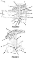
Figure 1 is an exploded perspective view of the distribution valve. -
Figure 2 is a cross-sectional perspective view of the distribution valve. -
Figure 3 is a perspective view of the gears and drive element comprised by the distribution valve in an assembled manner. -
Figure 4 shows top views of the plate of the distribution valve in different positions. -
Figure 5 is a perspective view of the drive element of the distribution valve. -
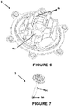
Figure 6 is a perspective view of the middle cover of the distribution valve. -
Figure 7 is a perspective view of the drive gear of the distribution valve. -
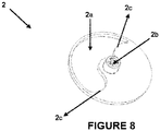
Figure 8 is a top perspective view of the plate of the distribution valve. - All the parts illustrated in the drawings are individually assigned a reference numeral and the corresponding terms of these numbers are listed as follows:
Distribution valve (D) Inlet (G) Outlet (C) Body (1) Plate (2) Opening (2a) Connection housing (2b) End portion (2c) Drive element (3) Blade (3a) Passage (3b) Drive gear (3c) First sealing member (3d) First transmission gear (4) Central gear (5) Connection end (5a) Second sealing member (5b) Rod (5c) Middle cover (6) Hole (6a) Support (6b) Upper cover (7) - Dishwashers, in which washing process of dishes are performed, comprise spray arms for spraying washing fluid (such as water or detergent water) to the dishes and a distribution valve for guiding the washing fluid to the preferred spray arm. The distribution valves usually comprise plates which leave openings for passage on the outlet so as to allow the washing fluid to exit the desired outlet after receiving the washing fluid. In the state-of-the-art, the plates generally have electronic components such as a motor, and they are driven by motors. However, the washing fluid circulating within the dishwasher may damage the electronic parts of the motor in the distribution valve, and the particles such as dust, food residue that may be present in the fluid may also hinder the operation of the components such as gears driving the plates. Therefore, with the present invention, there is developed a distribution valve which does not comprise an electronic component such as a motor and which prevents the fluid entering therein from blocking the movement of the components that drive the plate.
- The distribution valve (D) of the present invention, the exemplary views of which are shown in
Figures 1-7 , is suitable for use in a dishwasher and comprises at least one body (1) on which at least one inlet (G) in connection with a water supply, preferably mains water, and at least two outlets (C) in connection with at least two distributors (not shown in figures), preferably spray arms, are disposed; at least one plate (2) which is positioned such that it can rotate within the body (1) and allows the fluid within the body (1) to be fed into at least one of said outlets (C) while preventing the others from receiving the fluid; and at least one opening (2a) which is provided on the plate (2) and through which the fluid is passed to reach at least one outlet (C). The inventive distribution valve (D) also comprises at least one drive element (3) which is provided within the body (1) and allows the fluid to hit against at least one blade (3a) thereof after passing through the inlet (G) such that the fluid rotates around an axis in its center, and which has at least one passage (3b) through which the fluid hitting against the blade (3a) is passed to reach at least one outlet (C); at least one drive gear (3c) provided on the drive element (3); at least a first sealing member (3d) that is positioned on the side of the drive gear (3c) which faces the inlet (G) so as to prevent the fluid from reaching the drive gear (3c); at least a first transmission gear (4) which is in contact with the drive gear (3c) and makes a rotational movement by the motion of the drive gear (3c); and at least one central gear (5) to which the rotational motion transmitted by the first transmission gear (4) is transferred and which is connected on at least one end with the plate (2). - In an exemplary embodiment of the present invention, the water received from a water supply or the washing fluid mixed with cleaning agent is fed to a distribution valve (D) within a dishwasher. The fluid passes through the inlet (G) into the body (1) of the distribution valve (D) and hits against the blade (3a) of the drive element (3) within the body (1). With this force, the drive element (3) rotates around itself. Once the drive element (3) rotates, the drive gear (3c) thereon rotates and begins to rotate the first transmission gear (4). The first sealing member (3d) provided on the drive gear (3c) prevents the fluid from reaching the drive gear (3c) after passing through the inlet (G). In this manner, the particles (such as dust, dirt, food residue etc.), which may be present in the fluid, are prevented from being accumulated on the drive gear (3c) and from hindering movement of the first transmission gear (4). The first transmission gear (4) transfers the motion transmitted by the drive gear (3c) to the central gear (5).The central gear (5) is connected on one side with the plate (2), on which the opening (2a) is provided. Upon being driven by the central gear (5), the plate (2) rotates around itself and allows the fluid to enter into the outlet (C) that has the opening (2a) positioned thereon. In this case, fluid passage is not allowed into the outlets (C) which do not have any opening (2a) positioned thereon. As the fluid hits the blade (3a) and allows continuous rotation of the plate (2), the distributor to which the fluid is sent constantly changes. In this manner, it is ensured that the fluid reaches a wide area of the dishes present in the dishwasher by means of different distributors, while water consumption is reduced due to non-use of each distributor on a continuous basis.
- In an embodiment of the present invention, the central gear (5) preferably comprises, on its other end that is far from the end where it is connected to the first transmission gear (4), at least one connection end (5a), by which the central gear (5) is connected to the plate (2). According to this embodiment, the plate (2) in turn comprises at least one connection housing (2b) suitable for receiving the connection end (5a). As the connection end (5a) is inserted in the connection housing (2b), the plate (2) is enabled to rotate simultaneously with the central gear (5) such that a possible slipping thereof is avoided.
- In another embodiment of the present invention where the connection end (5a) is present, the central gear (5) comprises, on the side of the connection end (5a) which faces the first transmission gear (4), at least a second sealing member (5b) positioned so as to prevent the fluid therein from reaching the connection end (5a) (for example, a shrink fit not allowing the passage of the fluid through the central gear (5)). As the second sealing member (5b) prevents the fluid from contacting the connection end (5a), any solid particle that may be present in the fluid is prevented from attaching to the connection end (5a) and being accumulated within the connection housing (2b). Therefore, a robust and durable distribution valve (D) is obtained.
- In another preferred embodiment of the invention, the central gear (5) comprises at least one rod (5c) which connects the part where it is connected to the first transmission gear (4), with a certain distance therebetween, to the connection end (5a), wherein the rod (5c) preferably passes through the center of the drive gear (3c) of the drive element (3) and extends towards the plate (2). Thanks to the rod (5c), the central gear (5) and the first transmission gear (4) are able to be positioned as far as possible from the area where the drive element (3) is located and in which liquid exists. In this manner, a precaution is taken against the contact of the fluid with the central gear (5) and the first transmission gear (4).
- In another preferred embodiment of the present invention, the distribution valve (D) comprises at least a middle cover (6) which is positioned preferably on the upper side of the drive element (3) that is far from the floor within the body (1) and which is suitable for allowing the rod (5c) to pass through at least one hole (6a) located in the center thereof. In this embodiment, the central gear (5) and the first transmission gear (4) are located on the upper side of the middle cover (6) that is far from the floor.
- In an alternative embodiment of the invention, there is provided at least a second transmission gear between the first transmission gear (4) and the central gear (5), wherein the second transmission gear transmits the rotational motion received from the first transmission gear (4) to the central gear (5). By means of the second transmission gear, the rotational speed and rotational number of the central gear (5) and of the plate (2) connected thereto are able to be adjusted independently from the first transmission gear (4). In this embodiment, the distribution valve (D) comprises, preferably on the middle cover (6), at least two supports (6b) which are preferably in the form of a rod and on which the first transmission gear (4) and the second transmission gear can be placed so as to rotate thereon.
- In a preferred embodiment of the invention, the first transmission gear (4) and/or the second transmission gear comprise (s) at least two gears of different diameters, which are superimposed. According to this embodiment, the drive gear (3c) contacts a gear of the first transmission gear (4) and enables the first transmission gear (4) to rotate, whereas the other gear of a different diameter comprised by the first transmission gear (4) contacts a gear of the second transmission gear. As the second transmission gear starts to rotate, the other gear thereof that is not in contact with the first transmission gear (4) transmits the rotational motion to the central gear (5). By means of the superimposed gears comprised by the first transmission gear (4) and the second transmission gear, the amount and speed of rotation of the central gear (5) are able to be adjusted precisely by fitting as many gears as possible into a narrow area. In this embodiment, the supports (6b) comprised by the middle cover (6) have different lengths because the second transmission gear in contact with the first transmission gear (4) is positioned at different heights.
- In a preferred embodiment of the invention, the blade (3a) provided on the drive element (3) has a curved structure so as to be filled with the fluid such that the fluid received from the inlet (G) is able to exert enough force to rotate the drive element (3). By making maximum use of the water thanks to the curved structure, it is ensured that the drive element (3) is rotated even with a small amount of water.
- In another alternative embodiment of the invention, the distribution valve (D) comprises at least one upper cover (7) which covers the upper part of the body (1) that is far from the outlets (C). The upper cover (7) preferably comprises at least a mounting hole (not shown in figures) for connection thereof to the body (1). In this embodiment, the distribution valve (D) in turn comprises at least one connection member, which may be a screw, suitable for being inserted in the mounting hole.
- In another alternative embodiment, the distribution valve (D) comprises at least one gasket provided under the upper cover (7) and/or under middle cover (6). By means of the gasket, the leakage of the fluid within the distribution valve (D) is prevented. In this embodiment, the middle cover (6) in turn comprises at least one other mounting hole in alignment with the mounting hole of the upper cover (7). According to this embodiment, the connection member passes through mounting holes of the upper cover (7) and middle cover (6). Similarly, according to the same embodiment, the body (1) comprises at least one other mounting hole in alignment with the mounting holes of the middle cover (6) and the upper cover (7). In this embodiment, the connection member passes through the mounting holes on the middle cover (6), the upper cover (7) and the body (1) so as to connect these parts to each other.
- In another preferred embodiment of the invention, the opening (2a) provided on the plate (2) has a structure which always allows passage of as much fluid as a full width of the outlet (C). In other words, said opening (2a) permits passage of a certain amount of fluid to an outlet (C) while preventing passage of the same amount of fluid through another outlet (C). Therefore, in a preferred embodiment of the invention, angular distance between the successive outlets (C) is equal to each other. Furthermore, the angular width of the opening (2a) provided on the plate (2) is also equal to the angular distance between the successive outlets (C). For example, when the distribution valve (D) developed according to the present invention comprises two outlets (C), said outlets (C) are positioned so as to make an angle of 180° with respect to each other, and the angular width of the opening (2a) provided on the plate (2) is 180°. Similarly, when the distribution valve (D) developed according to the present invention comprises three outlets (C), said outlets (C) are positioned so as to make an angle of 120° with respect to each other, and the angular width of the opening (2a) provided on the plate (2) is 120°. In this manner, the opening (2a) permits passage to an outlet (C) while preventing passage to another outlet (C) to the same extent. In this embodiment, an end portion (2c) of said opening (2a) is in the form of a recess - shaped semicircle whereas the other end portion (2c) is in the form of a projection - shaped semicircle. The radius of said semi-circular forms is preferably equal to the radius of the outlets (C). Accordingly, it is ensured that the outlets (C) are opened and closed in a stable manner by means of the opening (2a).
- With the present invention, there is provided a distribution valve (D), which is not only safe due to not having any electronic component, but also robust and durable as it prevents the contact of the fluid with gears while enabling the fluid to be discharged through the desired outlet (C) in the dishwasher where it is used.
Claims (15)
- A distribution valve (D) which is suitable for use in dishwashers and comprises at least one body (1) on which at least one inlet (G) in connection with a water supply and at least two outlets (C) in connection with at least two distributors are disposed; at least one plate (2) which is positioned such that it can rotate within the body (1) and which allows the fluid within the body (1) to be fed into at least one of said outlets (C) while preventing the others from receiving the fluid; and at least one opening (2a) which is provided on the plate (2) and through which the fluid is passed to reach at least one outlet (C), characterized by comprising:• at least one drive element (3) which is provided within the body (1) and allows the fluid to hit against at least one blade (3a) thereof after passing through the inlet (G) such that the fluid rotates around an axis in its center, and which has at least one passage (3b) through which the fluid hitting against the blade (3a) is passed to reach at least one outlet (C);• at least one drive gear (3c) provided on the drive element (3);• at least a first sealing member (3d) which is positioned on the side of the drive gear (3c) that faces the inlet (G) so as to prevent the fluid from reaching the drive gear (3c);• at least a first transmission gear (4) which is in contact with the drive gear (3c) and makes a rotational movement by receiving the motion of the drive gear (3c); and• at least one central gear (5) to which the rotational motion transmitted by the first transmission gear (4) is transferred and which is connected, on at least one end, with the plate (2).
- A distribution valve (D) according to Claim 1, characterized by comprising at least one connection end (5a), by which the central gear (5) is connected to the plate (2).
- A distribution valve (D) according to Claim 2, characterized in that the connection end (5a) is located on the other end of the central gear (5) that is far from the end where the central gear (5) is connected to the first transmission gear (4).
- A distribution valve (D) according to Claim 2, characterized in that the plate (2) comprises at least one connection housing (2b) suitable for receiving the connection end (5a).
- A distribution valve (D) according to Claim 2, characterized in that the central gear (5) comprises, on the side of the connection end (5a) that faces the first transmission gear (4), at least a second sealing member (5b) positioned so as to prevent the fluid therein from reaching the connection end (5a).
- A distribution valve (D) according to Claim 1, characterized in that the central gear (5) comprises at least one rod (5c) which connects the part where it is connected to the first transmission gear (4), with a certain distance therebetween, to the connection end (5a),
- A distribution valve (D) according to Claim 6, characterized in that the rod (5c) is positioned such that it passes through the center of the drive gear (3c) so as to extend towards the plate (2).
- A distribution valve (D) according to Claim 6, characterized by comprising, within the body (1), at least one middle cover (6) which is suitable for allowing the rod (5c) to pass through at least one hole (6a) provided in the center thereof.
- A distribution valve (D) according to Claim 1, characterized by comprising at least a second transmission gear between the first transmission gear (4) and the central gear (5).
- A distribution valve (D) according to Claim 9, characterized in that it comprises, on the middle cover (6), at least two supports (6b) on which the first transmission gear (4) and the second transmission gear can be placed so as to rotate thereon.
- A distribution valve (D) according to Claim 10, characterized in that the supports (6b) are in the form of a rod.
- A distribution valve (D) according to Claim 1 or Claim 9, characterized in that the first transmission gear (4) and/or the second transmission gear comprise(s) at least two superimposed gears which have different diameters from each other.
- A distribution valve (D) according to Claim 1, characterized by comprising at least one upper cover (7) which covers the upper part of the body (1) that is far from the outlets (C).
- A distribution valve (D) according to Claim 1, characterized in that the angular distance between the successive outlets (C) is equal to each other.
- A distribution valve (D) according to Claim 14, characterized in that the angular width of the opening (2a) provided on the plate (2) is equal to the angular distance between the successive outlets (C).
Applications Claiming Priority (1)
| Application Number | Priority Date | Filing Date | Title |
|---|---|---|---|
| TR2016/03750A TR201603750A2 (en) | 2016-03-23 | 2016-03-23 | A divider. |
Publications (2)
| Publication Number | Publication Date |
|---|---|
| EP3222193A1 true EP3222193A1 (en) | 2017-09-27 |
| EP3222193B1 EP3222193B1 (en) | 2021-11-03 |
Family
ID=58544698
Family Applications (1)
| Application Number | Title | Priority Date | Filing Date |
|---|---|---|---|
| EP17162297.0A Active EP3222193B1 (en) | 2016-03-23 | 2017-03-22 | A distribution valve |
Country Status (2)
| Country | Link |
|---|---|
| EP (1) | EP3222193B1 (en) |
| TR (1) | TR201603750A2 (en) |
Cited By (3)
| Publication number | Priority date | Publication date | Assignee | Title |
|---|---|---|---|---|
| CN111102378A (en) * | 2020-01-07 | 2020-05-05 | 广东万和热能科技有限公司 | Fluid Transfer Valves and Combination Furnaces |
| EP3928677A1 (en) | 2020-06-22 | 2021-12-29 | Arçelik Anonim Sirketi | A dishwasher comprising a gear |
| EP3987997A1 (en) | 2020-10-23 | 2022-04-27 | Arçelik Anonim Sirketi | A dishwasher comprising a strainer |
Citations (4)
| Publication number | Priority date | Publication date | Assignee | Title |
|---|---|---|---|---|
| GB2023411A (en) * | 1978-06-19 | 1980-01-03 | Licentia Gmbh | Dishwashing machine |
| DE3525742A1 (en) * | 1985-07-19 | 1987-01-29 | Licentia Gmbh | Change-over valve for flowable media |
| EP1264570A1 (en) | 2000-02-14 | 2002-12-11 | Matsushita Electric Industrial Co., Ltd. | Washing machine |
| US20160066765A1 (en) * | 2014-09-10 | 2016-03-10 | General Electric Company | Turbine fluid diverter for an appliance |
-
2016
- 2016-03-23 TR TR2016/03750A patent/TR201603750A2/en unknown
-
2017
- 2017-03-22 EP EP17162297.0A patent/EP3222193B1/en active Active
Patent Citations (4)
| Publication number | Priority date | Publication date | Assignee | Title |
|---|---|---|---|---|
| GB2023411A (en) * | 1978-06-19 | 1980-01-03 | Licentia Gmbh | Dishwashing machine |
| DE3525742A1 (en) * | 1985-07-19 | 1987-01-29 | Licentia Gmbh | Change-over valve for flowable media |
| EP1264570A1 (en) | 2000-02-14 | 2002-12-11 | Matsushita Electric Industrial Co., Ltd. | Washing machine |
| US20160066765A1 (en) * | 2014-09-10 | 2016-03-10 | General Electric Company | Turbine fluid diverter for an appliance |
Cited By (3)
| Publication number | Priority date | Publication date | Assignee | Title |
|---|---|---|---|---|
| CN111102378A (en) * | 2020-01-07 | 2020-05-05 | 广东万和热能科技有限公司 | Fluid Transfer Valves and Combination Furnaces |
| EP3928677A1 (en) | 2020-06-22 | 2021-12-29 | Arçelik Anonim Sirketi | A dishwasher comprising a gear |
| EP3987997A1 (en) | 2020-10-23 | 2022-04-27 | Arçelik Anonim Sirketi | A dishwasher comprising a strainer |
Also Published As
| Publication number | Publication date |
|---|---|
| TR201603750A2 (en) | 2017-10-23 |
| EP3222193B1 (en) | 2021-11-03 |
Similar Documents
| Publication | Publication Date | Title |
|---|---|---|
| CN104271024B (en) | Device for moving a washing impeller for a washing device and/or a drying device | |
| JP7419071B2 (en) | Beverage extraction equipment that cleans the outer surface of the nozzle | |
| CN104284620B (en) | Washing components for washing machines and/or drying machines | |
| CN105307787B (en) | Band has the liquid injection system of the nozzle of two outlets | |
| CA1152411A (en) | Removable and self sealing spray manifold for commercial dishwasher | |
| US20100236588A1 (en) | Water-bearing domestic appliance with a water diverter | |
| EP3222193B1 (en) | A distribution valve | |
| US9661978B2 (en) | Spraying device for a washing machine | |
| EP3122228B1 (en) | Dishwasher comprising at least one dishwasher spray arm | |
| CN105534451B (en) | The washing methods of water tank cleaner | |
| DE102010043021B4 (en) | Dishwasher, in particular household dishwasher | |
| EP1183983B1 (en) | Spraying device for a dishwasher | |
| EP3785596A1 (en) | A dishwasher comprising a fruit and vegetable washing apparatus | |
| US20060054204A1 (en) | Warewash machine arm mount assembly | |
| WO2019206913A1 (en) | Domestic dishwasher having a spray device | |
| EP2687141A1 (en) | A dishwasher | |
| DE102006061082A1 (en) | Water-conducting household appliance with a detergent adding device | |
| EP4186407B1 (en) | Liquid sprayer for a dishwasher and dishwasher | |
| KR20120027463A (en) | Device for cleaning closed spaces | |
| KR20200068194A (en) | Nozzle and dishwasher including the same | |
| EP3683504B1 (en) | Oven comprising system for dispersing chemical agents | |
| US20110048470A1 (en) | Spray Assembly for Spraying Foam and Liquid for Cleaning a Surface and Also a Cleaning Installation and Method | |
| DE102009028280B4 (en) | Home appliance | |
| US8960207B2 (en) | Aqueous washer with rotating arms with nozzles | |
| EP4578364A1 (en) | A dishwasher providing intensive washing |
Legal Events
| Date | Code | Title | Description |
|---|---|---|---|
| PUAI | Public reference made under article 153(3) epc to a published international application that has entered the european phase |
Free format text: ORIGINAL CODE: 0009012 |
|
| STAA | Information on the status of an ep patent application or granted ep patent |
Free format text: STATUS: THE APPLICATION HAS BEEN PUBLISHED |
|
| AK | Designated contracting states |
Kind code of ref document: A1 Designated state(s): AL AT BE BG CH CY CZ DE DK EE ES FI FR GB GR HR HU IE IS IT LI LT LU LV MC MK MT NL NO PL PT RO RS SE SI SK SM TR |
|
| AX | Request for extension of the european patent |
Extension state: BA ME |
|
| STAA | Information on the status of an ep patent application or granted ep patent |
Free format text: STATUS: REQUEST FOR EXAMINATION WAS MADE |
|
| 17P | Request for examination filed |
Effective date: 20180320 |
|
| RBV | Designated contracting states (corrected) |
Designated state(s): AL AT BE BG CH CY CZ DE DK EE ES FI FR GB GR HR HU IE IS IT LI LT LU LV MC MK MT NL NO PL PT RO RS SE SI SK SM TR |
|
| GRAP | Despatch of communication of intention to grant a patent |
Free format text: ORIGINAL CODE: EPIDOSNIGR1 |
|
| STAA | Information on the status of an ep patent application or granted ep patent |
Free format text: STATUS: GRANT OF PATENT IS INTENDED |
|
| RIC1 | Information provided on ipc code assigned before grant |
Ipc: F16K 31/53 20060101ALI20210510BHEP Ipc: F16K 11/074 20060101ALI20210510BHEP Ipc: F16K 31/16 20060101ALI20210510BHEP Ipc: A47L 15/42 20060101AFI20210510BHEP |
|
| INTG | Intention to grant announced |
Effective date: 20210609 |
|
| GRAS | Grant fee paid |
Free format text: ORIGINAL CODE: EPIDOSNIGR3 |
|
| GRAA | (expected) grant |
Free format text: ORIGINAL CODE: 0009210 |
|
| STAA | Information on the status of an ep patent application or granted ep patent |
Free format text: STATUS: THE PATENT HAS BEEN GRANTED |
|
| AK | Designated contracting states |
Kind code of ref document: B1 Designated state(s): AL AT BE BG CH CY CZ DE DK EE ES FI FR GB GR HR HU IE IS IT LI LT LU LV MC MK MT NL NO PL PT RO RS SE SI SK SM TR |
|
| REG | Reference to a national code |
Ref country code: GB Ref legal event code: FG4D |
|
| REG | Reference to a national code |
Ref country code: AT Ref legal event code: REF Ref document number: 1443227 Country of ref document: AT Kind code of ref document: T Effective date: 20211115 Ref country code: CH Ref legal event code: EP |
|
| REG | Reference to a national code |
Ref country code: IE Ref legal event code: FG4D |
|
| REG | Reference to a national code |
Ref country code: DE Ref legal event code: R096 Ref document number: 602017048578 Country of ref document: DE |
|
| REG | Reference to a national code |
Ref country code: LT Ref legal event code: MG9D |
|
| REG | Reference to a national code |
Ref country code: NL Ref legal event code: MP Effective date: 20211103 |
|
| REG | Reference to a national code |
Ref country code: AT Ref legal event code: MK05 Ref document number: 1443227 Country of ref document: AT Kind code of ref document: T Effective date: 20211103 |
|
| PG25 | Lapsed in a contracting state [announced via postgrant information from national office to epo] |
Ref country code: RS Free format text: LAPSE BECAUSE OF FAILURE TO SUBMIT A TRANSLATION OF THE DESCRIPTION OR TO PAY THE FEE WITHIN THE PRESCRIBED TIME-LIMIT Effective date: 20211103 Ref country code: LT Free format text: LAPSE BECAUSE OF FAILURE TO SUBMIT A TRANSLATION OF THE DESCRIPTION OR TO PAY THE FEE WITHIN THE PRESCRIBED TIME-LIMIT Effective date: 20211103 Ref country code: FI Free format text: LAPSE BECAUSE OF FAILURE TO SUBMIT A TRANSLATION OF THE DESCRIPTION OR TO PAY THE FEE WITHIN THE PRESCRIBED TIME-LIMIT Effective date: 20211103 Ref country code: BG Free format text: LAPSE BECAUSE OF FAILURE TO SUBMIT A TRANSLATION OF THE DESCRIPTION OR TO PAY THE FEE WITHIN THE PRESCRIBED TIME-LIMIT Effective date: 20220203 Ref country code: AT Free format text: LAPSE BECAUSE OF FAILURE TO SUBMIT A TRANSLATION OF THE DESCRIPTION OR TO PAY THE FEE WITHIN THE PRESCRIBED TIME-LIMIT Effective date: 20211103 |
|
| PG25 | Lapsed in a contracting state [announced via postgrant information from national office to epo] |
Ref country code: IS Free format text: LAPSE BECAUSE OF FAILURE TO SUBMIT A TRANSLATION OF THE DESCRIPTION OR TO PAY THE FEE WITHIN THE PRESCRIBED TIME-LIMIT Effective date: 20220303 Ref country code: SE Free format text: LAPSE BECAUSE OF FAILURE TO SUBMIT A TRANSLATION OF THE DESCRIPTION OR TO PAY THE FEE WITHIN THE PRESCRIBED TIME-LIMIT Effective date: 20211103 Ref country code: PT Free format text: LAPSE BECAUSE OF FAILURE TO SUBMIT A TRANSLATION OF THE DESCRIPTION OR TO PAY THE FEE WITHIN THE PRESCRIBED TIME-LIMIT Effective date: 20220303 Ref country code: PL Free format text: LAPSE BECAUSE OF FAILURE TO SUBMIT A TRANSLATION OF THE DESCRIPTION OR TO PAY THE FEE WITHIN THE PRESCRIBED TIME-LIMIT Effective date: 20211103 Ref country code: NO Free format text: LAPSE BECAUSE OF FAILURE TO SUBMIT A TRANSLATION OF THE DESCRIPTION OR TO PAY THE FEE WITHIN THE PRESCRIBED TIME-LIMIT Effective date: 20220203 Ref country code: NL Free format text: LAPSE BECAUSE OF FAILURE TO SUBMIT A TRANSLATION OF THE DESCRIPTION OR TO PAY THE FEE WITHIN THE PRESCRIBED TIME-LIMIT Effective date: 20211103 Ref country code: LV Free format text: LAPSE BECAUSE OF FAILURE TO SUBMIT A TRANSLATION OF THE DESCRIPTION OR TO PAY THE FEE WITHIN THE PRESCRIBED TIME-LIMIT Effective date: 20211103 Ref country code: HR Free format text: LAPSE BECAUSE OF FAILURE TO SUBMIT A TRANSLATION OF THE DESCRIPTION OR TO PAY THE FEE WITHIN THE PRESCRIBED TIME-LIMIT Effective date: 20211103 Ref country code: GR Free format text: LAPSE BECAUSE OF FAILURE TO SUBMIT A TRANSLATION OF THE DESCRIPTION OR TO PAY THE FEE WITHIN THE PRESCRIBED TIME-LIMIT Effective date: 20220204 Ref country code: ES Free format text: LAPSE BECAUSE OF FAILURE TO SUBMIT A TRANSLATION OF THE DESCRIPTION OR TO PAY THE FEE WITHIN THE PRESCRIBED TIME-LIMIT Effective date: 20211103 |
|
| PG25 | Lapsed in a contracting state [announced via postgrant information from national office to epo] |
Ref country code: SM Free format text: LAPSE BECAUSE OF FAILURE TO SUBMIT A TRANSLATION OF THE DESCRIPTION OR TO PAY THE FEE WITHIN THE PRESCRIBED TIME-LIMIT Effective date: 20211103 Ref country code: SK Free format text: LAPSE BECAUSE OF FAILURE TO SUBMIT A TRANSLATION OF THE DESCRIPTION OR TO PAY THE FEE WITHIN THE PRESCRIBED TIME-LIMIT Effective date: 20211103 Ref country code: RO Free format text: LAPSE BECAUSE OF FAILURE TO SUBMIT A TRANSLATION OF THE DESCRIPTION OR TO PAY THE FEE WITHIN THE PRESCRIBED TIME-LIMIT Effective date: 20211103 Ref country code: EE Free format text: LAPSE BECAUSE OF FAILURE TO SUBMIT A TRANSLATION OF THE DESCRIPTION OR TO PAY THE FEE WITHIN THE PRESCRIBED TIME-LIMIT Effective date: 20211103 Ref country code: DK Free format text: LAPSE BECAUSE OF FAILURE TO SUBMIT A TRANSLATION OF THE DESCRIPTION OR TO PAY THE FEE WITHIN THE PRESCRIBED TIME-LIMIT Effective date: 20211103 Ref country code: CZ Free format text: LAPSE BECAUSE OF FAILURE TO SUBMIT A TRANSLATION OF THE DESCRIPTION OR TO PAY THE FEE WITHIN THE PRESCRIBED TIME-LIMIT Effective date: 20211103 |
|
| REG | Reference to a national code |
Ref country code: DE Ref legal event code: R097 Ref document number: 602017048578 Country of ref document: DE |
|
| PLBE | No opposition filed within time limit |
Free format text: ORIGINAL CODE: 0009261 |
|
| STAA | Information on the status of an ep patent application or granted ep patent |
Free format text: STATUS: NO OPPOSITION FILED WITHIN TIME LIMIT |
|
| 26N | No opposition filed |
Effective date: 20220804 |
|
| REG | Reference to a national code |
Ref country code: DE Ref legal event code: R084 Ref document number: 602017048578 Country of ref document: DE |
|
| PG25 | Lapsed in a contracting state [announced via postgrant information from national office to epo] |
Ref country code: MC Free format text: LAPSE BECAUSE OF FAILURE TO SUBMIT A TRANSLATION OF THE DESCRIPTION OR TO PAY THE FEE WITHIN THE PRESCRIBED TIME-LIMIT Effective date: 20211103 Ref country code: AL Free format text: LAPSE BECAUSE OF FAILURE TO SUBMIT A TRANSLATION OF THE DESCRIPTION OR TO PAY THE FEE WITHIN THE PRESCRIBED TIME-LIMIT Effective date: 20211103 |
|
| REG | Reference to a national code |
Ref country code: CH Ref legal event code: PL |
|
| PG25 | Lapsed in a contracting state [announced via postgrant information from national office to epo] |
Ref country code: SI Free format text: LAPSE BECAUSE OF FAILURE TO SUBMIT A TRANSLATION OF THE DESCRIPTION OR TO PAY THE FEE WITHIN THE PRESCRIBED TIME-LIMIT Effective date: 20211103 |
|
| REG | Reference to a national code |
Ref country code: BE Ref legal event code: MM Effective date: 20220331 |
|
| PG25 | Lapsed in a contracting state [announced via postgrant information from national office to epo] |
Ref country code: LU Free format text: LAPSE BECAUSE OF NON-PAYMENT OF DUE FEES Effective date: 20220322 Ref country code: LI Free format text: LAPSE BECAUSE OF NON-PAYMENT OF DUE FEES Effective date: 20220331 Ref country code: IE Free format text: LAPSE BECAUSE OF NON-PAYMENT OF DUE FEES Effective date: 20220322 Ref country code: CH Free format text: LAPSE BECAUSE OF NON-PAYMENT OF DUE FEES Effective date: 20220331 |
|
| PG25 | Lapsed in a contracting state [announced via postgrant information from national office to epo] |
Ref country code: BE Free format text: LAPSE BECAUSE OF NON-PAYMENT OF DUE FEES Effective date: 20220331 |
|
| PG25 | Lapsed in a contracting state [announced via postgrant information from national office to epo] |
Ref country code: IT Free format text: LAPSE BECAUSE OF FAILURE TO SUBMIT A TRANSLATION OF THE DESCRIPTION OR TO PAY THE FEE WITHIN THE PRESCRIBED TIME-LIMIT Effective date: 20211103 |
|
| PG25 | Lapsed in a contracting state [announced via postgrant information from national office to epo] |
Ref country code: HU Free format text: LAPSE BECAUSE OF FAILURE TO SUBMIT A TRANSLATION OF THE DESCRIPTION OR TO PAY THE FEE WITHIN THE PRESCRIBED TIME-LIMIT; INVALID AB INITIO Effective date: 20170322 |
|
| PG25 | Lapsed in a contracting state [announced via postgrant information from national office to epo] |
Ref country code: MK Free format text: LAPSE BECAUSE OF FAILURE TO SUBMIT A TRANSLATION OF THE DESCRIPTION OR TO PAY THE FEE WITHIN THE PRESCRIBED TIME-LIMIT Effective date: 20211103 Ref country code: CY Free format text: LAPSE BECAUSE OF FAILURE TO SUBMIT A TRANSLATION OF THE DESCRIPTION OR TO PAY THE FEE WITHIN THE PRESCRIBED TIME-LIMIT Effective date: 20211103 |
|
| PG25 | Lapsed in a contracting state [announced via postgrant information from national office to epo] |
Ref country code: MT Free format text: LAPSE BECAUSE OF FAILURE TO SUBMIT A TRANSLATION OF THE DESCRIPTION OR TO PAY THE FEE WITHIN THE PRESCRIBED TIME-LIMIT Effective date: 20211103 |
|
| PGFP | Annual fee paid to national office [announced via postgrant information from national office to epo] |
Ref country code: GB Payment date: 20260324 Year of fee payment: 10 |
|
| PGFP | Annual fee paid to national office [announced via postgrant information from national office to epo] |
Ref country code: DE Payment date: 20260319 Year of fee payment: 10 |
|
| PGFP | Annual fee paid to national office [announced via postgrant information from national office to epo] |
Ref country code: FR Payment date: 20260320 Year of fee payment: 10 |
|
| PGFP | Annual fee paid to national office [announced via postgrant information from national office to epo] |
Ref country code: TR Payment date: 20260316 Year of fee payment: 10 |