EP3222093B1 - Enabling proximity operations with long-range wireless communication interfaces - Google Patents
Enabling proximity operations with long-range wireless communication interfaces Download PDFInfo
- Publication number
- EP3222093B1 EP3222093B1 EP15842619.7A EP15842619A EP3222093B1 EP 3222093 B1 EP3222093 B1 EP 3222093B1 EP 15842619 A EP15842619 A EP 15842619A EP 3222093 B1 EP3222093 B1 EP 3222093B1
- Authority
- EP
- European Patent Office
- Prior art keywords
- wifi
- data packets
- data
- proximity
- interface
- Prior art date
- Legal status (The legal status is an assumption and is not a legal conclusion. Google has not performed a legal analysis and makes no representation as to the accuracy of the status listed.)
- Active
Links
Images

Classifications
-
- H—ELECTRICITY
- H04—ELECTRIC COMMUNICATION TECHNIQUE
- H04L—TRANSMISSION OF DIGITAL INFORMATION, e.g. TELEGRAPHIC COMMUNICATION
- H04L67/00—Network arrangements or protocols for supporting network services or applications
- H04L67/50—Network services
- H04L67/54—Presence management, e.g. monitoring or registration for receipt of user log-on information, or the connection status of the users
-
- H—ELECTRICITY
- H04—ELECTRIC COMMUNICATION TECHNIQUE
- H04B—TRANSMISSION
- H04B17/00—Monitoring; Testing
- H04B17/30—Monitoring; Testing of propagation channels
- H04B17/309—Measuring or estimating channel quality parameters
- H04B17/318—Received signal strength
-
- H—ELECTRICITY
- H04—ELECTRIC COMMUNICATION TECHNIQUE
- H04L—TRANSMISSION OF DIGITAL INFORMATION, e.g. TELEGRAPHIC COMMUNICATION
- H04L67/00—Network arrangements or protocols for supporting network services or applications
- H04L67/34—Network arrangements or protocols for supporting network services or applications involving the movement of software or configuration parameters
-
- H—ELECTRICITY
- H04—ELECTRIC COMMUNICATION TECHNIQUE
- H04W—WIRELESS COMMUNICATION NETWORKS
- H04W64/00—Locating users or terminals or network equipment for network management purposes, e.g. mobility management
- H04W64/003—Locating users or terminals or network equipment for network management purposes, e.g. mobility management locating network equipment
-
- H—ELECTRICITY
- H04—ELECTRIC COMMUNICATION TECHNIQUE
- H04W—WIRELESS COMMUNICATION NETWORKS
- H04W84/00—Network topologies
- H04W84/02—Hierarchically pre-organised networks, e.g. paging networks, cellular networks, WLAN [Wireless Local Area Network] or WLL [Wireless Local Loop]
- H04W84/10—Small scale networks; Flat hierarchical networks
- H04W84/12—WLAN [Wireless Local Area Networks]
Definitions
- This specification is directed, in general, to wireless communications, and, more specifically, to systems and methods for enabling proximity operations with long-range wireless communication interfaces.
- the need for positive presence validation is quite a common task in a large variety of use cases that involve wireless communications. It is primarily a result of the fact that typically when a wireless medium is involved, peer devices can be physically located elsewhere (theoretically, anywhere in the network). There are use cases in which co-location of the parties is important and cannot be avoided. In these cases, mechanisms for ensuring device co-location are necessary.
- the various use cases may be clustered into several domains, including, but not limited to: (a) registration during authentication, (b) peer validation or verification, and (c) personalization or customization.
- Registration during authentication ensures that the party involved in a registration or authentication procedure is indeed physically located in the close vicinity of one another and therefore may be trusted.
- An example of registration during authentication includes the initial pairing with an access point (AP) or with another peer (P2P) device.
- Peer validation or verification is another mechanism for presence detection. For instance, peer validation may be used for admission control, allowing only users at certain physical distance to gain access (e.g., a café hotspot that limits access to a certain range, rather than the full WiFi range).
- personalization or customization involves the use of dynamically enabled services. For example, dynamically personalized data may be presented by a system if the system knows that the data is being observed by a relevant peer (e.g., a vending machine or other electronic terminal displays preferences or payment options specific to a nearby user).
- proximity has been determined by causing a user to physically press a button on the peer device thereby proving physical access to it, or by asking that the user type a personal identification number (PIN) code or the like presented by the peer device as way of proving it is actually being observed by the user.
- PIN personal identification number
- proximity may also be determined using dedicated wireless communication technologies- e.g ., Near Field Communications (NFC) or Radio Frequency Identification (RFID)-that are entirely distinct from the main wireless communication technology (e.g. , WiFi, WiMAX, etc.).
- NFC Near Field Communications
- RFID Radio Frequency Identification
- WO2010092499A1 discloses a motion detection system and method with null points.
- US2013309969A1 discloses an authentication for near field communications.
- EP2725834A1 discloses a method for providing a device ID of a short distance communication device to an authentication process, computer programme at short distance communication receiver.
- Yoshiaki Hori et al. The 2005 Symposium on Cryptography and Information Security Maiko Kobe, Japan, Jan. 25-28, 2005, The Institute of Electronics, Information and Communication Engineers, JP, vol. IC3-2 25 January 2005, pages 1-7 discloses a security evaluation for MIS protocol in Wireless LAN.
- a method may include transmitting a plurality of data packets using a WiFi interface of a first device, where each data packet has a signal strength following a predetermined pattern; and receiving an indication, via the WiFi interface, of whether the predetermined pattern has been identified by a second device.
- the first device may include a WiFi access point and the second device may include a mobile device.
- the WiFi interface may include an impedance matching circuit coupled to an antenna. Transmitting the plurality of data packets further may include purposefully deteriorating the signal strength of one or more of the plurality of data packets according to the predetermined pattern.
- the predetermined pattern may be configured to emulate a physical movement of the second device with respect to the first device. For instance, in some cases the physical movement may include a swiping motion of the second device with respect to the first device.
- the second device may be configured to identify the pattern by comparing the relative signal strength of received data packets with an expected pattern.
- one or more of the plurality of data packets may include configuration data in a payload portion usable by the second device to perform configuration operation.
- a method may include configuring an impedance matching circuit of a WiFi interface to provide a first amount of signal degradation; transmitting a first packet via the WiFi interface; configuring the impedance matching circuit of the WiFi interface to provide a second amount of signal degradation different from the first amount of degradation; transmitting a second packet via the WiFi interface, where a difference between the first and second amounts of signal degradation is identifiable by another electronic device in communication with the electronic device during a proximity operation; and receiving an indication from the other electronic device of whether the difference between the first and second amounts of signal degradation is proportional to an expected difference.
- the proximity operation may include a pairing operation, a validation operation, or a personalization operation.
- the method may also include configuring the impedance matching circuit of the WiFi interface to provide a third amount of signal degradation; transmitting a third packet via the WiFi interface, where a difference between the second and third amounts of signal degradation is identifiable by the other electronic device during the proximity operation; and receiving an indication from the other electronic device of whether the difference between the third and second amounts of signal degradation is proportional to another expected difference.
- another method may include receiving a plurality of data packets via a wireless communication interface, where each data packet has a radio frequency (RF) signal power that follows a time-varying pattern; and transmitting an indication, via the wireless communication interface as part of a proximity operation, of whether the time-varying pattern matches a predetermined pattern.
- RF radio frequency
- one or more communications devices or computer systems may perform one or more of the techniques described herein.
- a tangible computer-readable or electronic storage medium may have program instructions stored thereon that, upon execution by one or more communications devices or computer systems, cause the one or more communications devices or computer systems to execute one or more operations disclosed herein.
- a communications system or device may include at least one processor and a memory coupled to the at least one processor. Examples of a processor include, but are not limited to, a digital signal processor (DSP), an application specific integrated circuit (ASIC), a system-on-chip (SoC) circuit, a field-programmable gate array (FPGA), a microprocessor, or a microcontroller.
- the memory may be configured to store program instructions executable by the at least one processor to cause the system to execute one or more operations disclosed herein.
- systems and methods described herein enable one or more proximity operations-which would otherwise require the implementation of dedicated, short-range wireless communications (e.g. , Near Field Communications, Radio Frequency Identification, low-power Bluetooth, etc.)-to be instead performed over a long-range wireless communications (e.g ., WiFi, WiMAX, etc.).
- a given device may determine whether another device is physically close to it using a long-range wireless communication interface. Examples of operations that may be triggered in response to a proximity determination include, but are not limited to, pairing, validation, and personalization.
- a combination of hardware and software may enable the proximity experience based on an already available long-range wireless communication medium, thus making the experience inherent and self-contained without a need to involve a separate, short-range alternative channel (e.g. , NFC).
- a separate, short-range alternative channel e.g. , NFC
- hardware changes may be applied at the reference design level without requiring internal change to the silicon.
- hardware changes may be implemented on one device, and therefore does not imply that both terminals be altered to support these capabilities. This facilitates the introduction of devices into already deployed networks without massive deployment implications, thereby increasing its viability.
- the systems and methods described herein involve, from a hardware perspective, manipulation of a radio frequency (RF) signal path that has a controllable matching circuitry (or anti-matching), such that it can purposefully decay or degrade the RF signal to low power levels.
- RF radio frequency
- an access point or other network device may be configured to control the matching circuitry. This provides the ability to artificially control the perceived range by peer devices through transmitted signal strength.
- a stream of packets sent by a communication device may follow the standard WiFi exchange protocol.
- one or more packets may be arbitrarily sent through the proximity terminal of the device; that is, the device's RF path for short-range communications.
- the communication device may also choose to conduct the scanning using the proximity terminal.
- the packet stream sent may include specific content so that it may be detected by the peer device based on its content (e.g. , using the type, subtype and source address in the 802.11 MAC header fields; or alternatively with a specific information element attached to the packet).
- packets of management type (00), with reserved subtype (0111) may be used because of to their short nature and the ability to exchange them prior to connection.
- FIGURE 1 is a block diagram of an example of environment 100 where systems and methods for enabling proximity operations with long-range wireless interfaces may be implemented, according to some embodiments.
- wireless access point 101 is coupled to gateway 102, which in turn is coupled to network 103 (e.g., the Internet).
- Wireless access point 101 is configured to provide devices 104A-N and 105A- N (e.g., mobile communication devices, cellular phones, tablets, laptop computers, desktop computers, smart appliances, etc.) with access to network 103 via a long-range communication interface.
- devices 104A-N and 105A- N e.g., mobile communication devices, cellular phones, tablets, laptop computers, desktop computers, smart appliances, etc.
- WiFi long-range wireless communication interface
- IEEE 802.11 IEEE 802.11 standard
- communication range 107 of a WiFi interface is of the order of ⁇ 10 m to ⁇ 100 m when environment 100 is indoors, and may vary between ⁇ 100 m to ⁇ 500 m when environment 100 is outdoors.
- short-range wireless communication technologies such as NFC, for example, which typically has proximity range 106 of less than ⁇ 0.2 m.
- peers devices in order to implement systems and methods described herein, neither hardware nor software changes are required on devices 104A-N or 105A-N ("peer devices” or “peer terminals”). These systems and methods may therefore be used with any existing peer device, for example, for simple and easy pairing between access point 101 and device 104N. Additionally or alternatively, software changes may be made to the peer device to provide additional level of security as well the possibility for out-of-band data exchange channel.
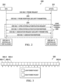
- FIGURE 2 is a message diagram of an example of a wireless connection exchange sequence usable to implement systems and methods for proximity WiFi according to some embodiments.
- access point station AP STA 201 receives an IEEE 802.11 "PROBE REQUEST" message 203 from station STA 202 ( e.g., device 104N in FIGURE 1 ).
- AP STA 201 sends an IEEE 802.11 "PROBE RESPONSE" message 204 to STA 202.
- messages 203 and 204 are received and transmitted by AP STA 201, respectively, over its WiFi interface-that is, using its WiFi antenna and corresponding RF circuitry.
- Messages 205 may be received and transmitted by AP STA 201 over its short-range wireless communication interface or proximity terminal-for instance, using an NFC antenna and associated RF circuitry.
- Examples of messages 205 may include an "OPEN SYSTEM AUTHENTICATION REQUEST" message transmitted by STA 202 to AP STA 201, an "OPEN SYSTEM AUTHENTICATION RESPONSE” message transmitted by AP STA 201 to STA 202, an "ASSOCIATION REQUEST” message transmitted by STA 202 to AP STA 201, and an "ASSOCIATION RESPONSE” message transmitted by AP STA 201 to STA 202.
- the WiFi port may be blocked in AP STA 201 and/or STA 202.
- FIGURE 2 allows STA 202 to participate in a proximity transaction with AP STA 201 by redirecting at least a portion of a WiFi message exchange through a short-range RF circuit.
- a short-range RF circuit may not be available or may not be necessary, as described in more detail below.
- FIGURE 3 is a block diagram of an example of sequence of data packets 300 usable to implement systems and methods for proximity WiFi according to some embodiments.
- the device sending stream of packets 300 e.g., access point 101 of FIGURE 1
- the device sending stream of packets 300 has the ability to arbitrarily control the matching of the device RF terminal thereby allowing it to generate a transmission with a time-varying signal strength pattern on a per packet basis.
- the peer device may be configured to detect this stream based on packet type and content. While the stream is sent, the receiving station identifies and extracts the changing power pattern of packets 300-1 through 300- N , and stores that information.
- the identified time-varying pattern may be correlated against expected admission sequence (e.g. , password), or may serve in a later phase to be cross-checked with device provided information (e.g. , unique device ID).
- the relative power difference between subsequently received packets may be stored, so that a comparison may be performed on a relative (rather than absolute) basis.
- the time-varying pattern may be configured to simulate a physical movement between devices. For example, in order to simulate a swiping motion, the time-varying pattern may start with a lowest power level and progressively increase that level as subsequent packets are transmitted up until a maximum or peak power value, and then the power level may be reduced back to the initial level. These power variations may be linearly, quadratically, randomly or arbitrarily implemented.
- packets that constitute the stream may carry additional data to be delivered to the peer device.
- FIGURE 4 is a block diagram of an example of radio frequency (RF) circuit 400 configured to implement systems and methods for proximity WiFi according to some embodiments.
- WiFi solution 401 may include a digital circuit configured to implement a WiFi communication standard.
- Multiplexer 402 is coupled to WiFi solution 401, and is also coupled to first RF antenna 403.
- Matching circuit 404 is coupled to a second output of multiplexer 402 and to second antenna 405.
- antenna 403 may be a long-range communication antenna, whereas antenna 405 may be a short-range communication antenna. In other implementations, however, a single antenna may be used and/or multiplexer 402 may be absent.
- WiFi solution 401 may be further configured (via software and/or firmware) to control matching circuitry 404.
- WiFi solution 401 may send control signals to matching circuit 404 to control an impedance matching and therefore purposefully degrade or otherwise reduce the RF power of transmitted signals on a per-packet basis.
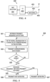
- FIGURE 5 is a flowchart of an example of method 500 for proximity WiFi.
- method 500 may be implemented by access point 101 of FIGURE 1 using RF circuit 400 of FIGURE 4 as part of its WiFi interface.
- method 500 may include retrieving (e.g. , from a memory) or otherwise identifying a time-varying, proximity sequence or pattern to be used in the proximity operation.
- method 500 includes configuring an impedance matching circuit of a WiFi interface to provide a first amount of signal degradation, and at block 503 method 500 includes transmitting a corresponding data packet.
- method 500 includes determining whether the transmitted data packet is the last data packet in the sequence. If not, control returns to blocks 502 and 503 where subsequent packet(s) are transmitted with a corresponding power level.
- block 505 analyzes a response has been received from the peer device indicating whether the sequence received by the peer device matches the transmitted sequence. If not, proximity is not detected at block 506. For example, device 104N of FIGURE 1 may be disposed outside or beyond the reach of proximity zone 106.
- a proximity operation may be triggered at block 507.
- a pairing operation or the like may be initiated in response to device 104N being within proximity zone 106.
- a difference between the first and second amounts of signal degradation may be identifiable prior to block 505 being executed.
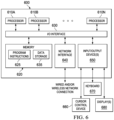
- system 600 may be implemented as a communication device, modem, data concentrator, server, a mainframe computer system, a workstation, a network computer, a desktop computer, a laptop, mobile device, or the like ( e.g., devices 101, 102, 104A- N , and/or 105A- N ).
- these various systems may be configured to communicate with each other in any suitable way, such as, for example, via a local area network or the like. It should be understood, however, that in various embodiments system 600 may be more or less complex, and may have more or fewer components, than shown in this example.
- system 600 may include one or more processor(s) 610A-N coupled to a system memory 620 via an input/output (I/O) interface 630.
- System 600 may furthe includes a network interface 640 coupled to I/O interface 630, and one or more input/output devices 625, such as cursor control device 660, keyboard 670, display(s) 680, and/or mobile device 690.
- system 600 may be a single-processor system including one processor 610, or a multi-processor system including two or more processors 610A- N ( e.g. , two, four, eight, or another suitable number).
- Processors 610 may be any processor capable of executing program instructions.
- System memory 620 may be configured to store program instructions and/or data accessible by processor 610.
- system memory 620 may be implemented using any suitable memory technology, such as static random access memory (SRAM), synchronous dynamic RAM (SDRAM), nonvolatile/Flash-type memory, or any other type of memory.
- SRAM static random access memory
- SDRAM synchronous dynamic RAM
- program instructions and data implementing certain operations such as, for example, those described in the figures above, may be stored within system memory 620 as program instructions 625 and data storage 635, respectively.
- program instructions and/or data may be received, sent or stored upon different types of computer-accessible media or on similar media separate from system memory 620 or computer system 600.
- a computer-accessible medium may include any tangible storage media or memory media such as magnetic or optical media- e.g ., disk or CD/DVD-ROM coupled to computer system 600 via I/O interface 630.
- Program instructions and data stored on a tangible computer-accessible medium in non-transitory form may further be transmitted by transmission media or signals such as electrical, electromagnetic, or digital signals, which may be conveyed via a communication medium such as a network and/or a wireless link, such as may be implemented via network interface 640.
- I/O interface 630 may be configured to coordinate I/O traffic between processor(s) 610A- N , system memory 620, and any peripheral devices in the device, including network interface 640 or other peripheral interfaces, such as input/output devices 650.
- I/O interface 630 may perform any necessary protocol, timing or other data transformations to convert data signals from one component (e.g. , system memory 620) into a format suitable for use by another component ( e.g. , processor(s) 610A- N ).
- I/O interface 630 may include support for devices attached through various types of peripheral buses, such as a variant of the Peripheral Component Interconnect (PCI) bus standard or the Universal Serial Bus (USB) standard, for example.
- PCI Peripheral Component Interconnect
- USB Universal Serial Bus
- the function of I/O interface 630 may be split into two or more separate components, such as a north bridge and a south bridge, for example.
- some or all of the functionality of I/O interface 630 such as an interface to system memory 620, may be incorporated directly into processor(s) 610A- N .
- Network interface 640 may be configured to allow data to be exchanged between system 600 and other devices attached to a network, such as other communication or computer systems, or between nodes of system 600.
- network interface 640 may support communication via wired or wireless general data networks, such as any suitable type of Ethernet network, for example; via telecommunications/telephony networks such as analog voice networks or digital fiber communications networks; via storage area networks such as Fibre Channel SANs, or via any other suitable type of network and/or protocol.
- network interface 640 may include RF interface 400 of FIGURE 4 , or the like.
- Input/output devices 650 may, in some embodiments, include one or more display terminals, keyboards, keypads, touchpads, scanning devices, voice or optical recognition devices, mobile devices, or any other devices suitable for entering or retrieving data by one or more system 600. Multiple input/output devices 650 may be present in computer system 600 or may be distributed on various nodes of system 600. In some embodiments, similar input/output devices may be separate from system 600 and may interact with one or more nodes of system 600 through a wired or wireless connection, such as over network interface 640.
- memory 620 may include program instructions 625 configured to implement certain embodiments described herein (e.g. , implementing one or more operations shown in FIGURE 5 ), and data storage 635 comprising various data accessible by program instructions 625.
- program instructions 625 may include software elements of embodiments illustrated in the above figures.
- program instructions 625 may be implemented in various embodiments using any desired programming language, scripting language, or combination of programming languages and/or scripting languages (e.g. , C, C++, C#, JAVA ® , JAVASCRIPT ® , PERL ® , etc.).
- Data storage 635 may include data that may be used in these embodiments ( e.g. , recorded communications, profiles for different modes of operations, etc.). In other embodiments, other or different software elements and data may be included.
- system 600 is merely illustrative and is not intended to limit the scope of the disclosure described herein.
- a computer system and devices may include any combination of hardware or software that can perform the indicated operations.
- the operations performed by the illustrated components may, in some embodiments, be performed by fewer components or distributed across additional components.
- the operations of some of the illustrated components may not be provided and/or other additional operations may be available. That is, the importance of the presence of other peripherals is secondary and not mandatory for successful implementation of the various embodiments. Accordingly, systems and methods described herein may be implemented or executed with other configurations.
- processor-readable, computer-readable, or machine-readable medium may include any device or medium that can store or transfer information. Examples of such a processor-readable medium include an electronic circuit, a semiconductor memory device, a flash memory, a ROM, an erasable ROM (EROM), a floppy diskette, a compact disk, an optical disk, a hard disk, a fiber optic medium, etc.
- Software code segments may be stored in any volatile or nonvolatile storage device, such as a hard drive, flash memory, solid state memory, optical disk, CD, DVD, computer program product, or other memory device, that provides tangible computer-readable or machine-readable storage for a processor or a middleware container service.
- the memory may be a virtualization of several physical storage devices, where the physical storage devices are of the same or different kinds.
- the code segments may be downloaded or transferred from storage to a processor or container via an internal bus, another computer network, such as the Internet or an intranet, or via other wired or wireless networks.
Landscapes
- Engineering & Computer Science (AREA)
- Computer Networks & Wireless Communication (AREA)
- Signal Processing (AREA)
- Quality & Reliability (AREA)
- Physics & Mathematics (AREA)
- Electromagnetism (AREA)
- Mobile Radio Communication Systems (AREA)
- Telephone Function (AREA)
Applications Claiming Priority (2)
| Application Number | Priority Date | Filing Date | Title |
|---|---|---|---|
| US14/486,660 US9553941B2 (en) | 2014-09-15 | 2014-09-15 | Enabling proximity operations with long-range wireless communication interfaces |
| PCT/US2015/050249 WO2016044311A1 (en) | 2014-09-15 | 2015-09-15 | Enabling proximity operations with long-range wireless communication interfaces |
Publications (3)
| Publication Number | Publication Date |
|---|---|
| EP3222093A1 EP3222093A1 (en) | 2017-09-27 |
| EP3222093A4 EP3222093A4 (en) | 2018-08-22 |
| EP3222093B1 true EP3222093B1 (en) | 2025-06-11 |
Family
ID=55456024
Family Applications (1)
| Application Number | Title | Priority Date | Filing Date |
|---|---|---|---|
| EP15842619.7A Active EP3222093B1 (en) | 2014-09-15 | 2015-09-15 | Enabling proximity operations with long-range wireless communication interfaces |
Country Status (5)
| Country | Link |
|---|---|
| US (1) | US9553941B2 (cg-RX-API-DMAC7.html) |
| EP (1) | EP3222093B1 (cg-RX-API-DMAC7.html) |
| JP (1) | JP6646189B2 (cg-RX-API-DMAC7.html) |
| CN (1) | CN106576311B (cg-RX-API-DMAC7.html) |
| WO (1) | WO2016044311A1 (cg-RX-API-DMAC7.html) |
Families Citing this family (3)
| Publication number | Priority date | Publication date | Assignee | Title |
|---|---|---|---|---|
| US10397767B2 (en) * | 2015-11-02 | 2019-08-27 | Apple Inc. | NAN further availability schedule indications |
| FR3060251B1 (fr) * | 2016-12-09 | 2019-05-10 | Sagemcom Broadband Sas | Procede d'appairage d'un terminal de type wi-fi a un point d'acces de type wi-fi |
| US10992561B2 (en) * | 2018-02-22 | 2021-04-27 | Rohde & Schwarz Gmbh & Co. Kg | Measuring device and measuring method for OFDMA testing |
Citations (1)
| Publication number | Priority date | Publication date | Assignee | Title |
|---|---|---|---|---|
| EP2725834A1 (en) * | 2012-10-29 | 2014-04-30 | Souffiane Houti | Method for providing a device ID of a short distance communication device to an authentication process, computer programme at short distance communication receiver |
Family Cites Families (20)
| Publication number | Priority date | Publication date | Assignee | Title |
|---|---|---|---|---|
| US5220678A (en) * | 1991-08-12 | 1993-06-15 | Motorola, Inc. | Method and apparatus for adjusting the power of a transmitter |
| GB2362542A (en) | 2000-05-05 | 2001-11-21 | Nokia Mobile Phones Ltd | Establishing communications with a proximate wireless device |
| GB0217707D0 (en) * | 2002-07-31 | 2002-09-11 | Koninkl Philips Electronics Nv | System for locating a mobile unit |
| US20060239291A1 (en) * | 2005-04-26 | 2006-10-26 | Birchler Mark A | Method and apparatus for determining a best route within an ad-hoc communication system |
| JP2007258944A (ja) * | 2006-03-22 | 2007-10-04 | Renesas Technology Corp | 無線通信システム |
| JP2009231973A (ja) * | 2008-03-19 | 2009-10-08 | Sony Corp | 無線通信システム、無線通信装置、認証方法、及びプログラム |
| EP2396775A1 (en) | 2009-02-11 | 2011-12-21 | Koninklijke Philips Electronics N.V. | Motion detection system and method with null points |
| US20100278345A1 (en) * | 2009-05-04 | 2010-11-04 | Thomas Matthieu Alsina | Method and apparatus for proximity based pairing of mobile devices |
| US20100323717A1 (en) | 2009-06-23 | 2010-12-23 | Qualcomm Incorporated | Method and apparatus for facilitating proximity detection in a wireless network |
| US8376853B2 (en) * | 2009-09-02 | 2013-02-19 | Appturn, Inc. | Hand held self-orientating targeting game |
| US8989672B2 (en) * | 2011-01-07 | 2015-03-24 | Apple Inc. | Methods for adjusting radio-frequency circuitry to mitigate interference effects |
| CN103444163B (zh) * | 2011-02-05 | 2017-03-22 | 苹果公司 | 用于移动位置确定的方法和设备 |
| US10223743B2 (en) * | 2011-03-29 | 2019-03-05 | Blackberry Limited | Communication system providing near field communication (NFC) transaction features and related methods |
| US8929838B2 (en) * | 2011-06-30 | 2015-01-06 | Motorola Mobility Llc | System and methods for adaptive antenna optimization |
| US9137753B2 (en) | 2011-08-08 | 2015-09-15 | Htc Corporation | Method for controlling transmission power of wireless device |
| US9092969B2 (en) * | 2011-12-29 | 2015-07-28 | Verizon Patent And Licensing Inc. | Method and system for invoking a security function of a device based on proximity to another device |
| US8953720B1 (en) * | 2012-01-20 | 2015-02-10 | Marvell International Ltd. | Packet type auto-detection in a wireless local area network (WLAN) |
| GB2502263A (en) | 2012-05-16 | 2013-11-27 | Ibm | Authentication using near field communication with varied signal strength |
| WO2014125336A1 (en) * | 2013-02-15 | 2014-08-21 | Nokia Corporation | Signal handling |
| US9930689B2 (en) * | 2013-05-08 | 2018-03-27 | Blackberry Limited | Proximity signaling and procedure for LTE |
-
2014
- 2014-09-15 US US14/486,660 patent/US9553941B2/en active Active
-
2015
- 2015-09-15 EP EP15842619.7A patent/EP3222093B1/en active Active
- 2015-09-15 WO PCT/US2015/050249 patent/WO2016044311A1/en not_active Ceased
- 2015-09-15 CN CN201580040046.9A patent/CN106576311B/zh active Active
- 2015-09-15 JP JP2017533741A patent/JP6646189B2/ja active Active
Patent Citations (1)
| Publication number | Priority date | Publication date | Assignee | Title |
|---|---|---|---|---|
| EP2725834A1 (en) * | 2012-10-29 | 2014-04-30 | Souffiane Houti | Method for providing a device ID of a short distance communication device to an authentication process, computer programme at short distance communication receiver |
Non-Patent Citations (1)
| Title |
|---|
| YOSHIAKI HORI ET AL: "Security evaluation for MIS protocol in Wireless LAN", vol. IC3-2, 25 January 2005 (2005-01-25), pages 1 - 7, XP009522019, Retrieved from the Internet <URL:https://img.atwikiimg.com/www23.atwiki.jp/hudikaha/pub/1C3-2.pdf> * |
Also Published As
| Publication number | Publication date |
|---|---|
| CN106576311B (zh) | 2020-10-16 |
| JP6646189B2 (ja) | 2020-02-14 |
| US20160080511A1 (en) | 2016-03-17 |
| CN106576311A (zh) | 2017-04-19 |
| EP3222093A1 (en) | 2017-09-27 |
| EP3222093A4 (en) | 2018-08-22 |
| WO2016044311A1 (en) | 2016-03-24 |
| US9553941B2 (en) | 2017-01-24 |
| JP2017531408A (ja) | 2017-10-19 |
Similar Documents
| Publication | Publication Date | Title |
|---|---|---|
| WO2019052532A1 (zh) | 关于物联网设备的信息交互方法、装置及设备 | |
| US11419014B2 (en) | Device for wireless communication handover | |
| EP3080704B1 (en) | Automatic internet sharing | |
| TWI724019B (zh) | 用於測試低功率射頻(rf)資料封包信號收發器之方法 | |
| EP2957090B1 (en) | Specifying link layer information in a url | |
| KR20150121723A (ko) | 근거리 통신을 이용하여 피어-2-피어 wi-fi 레인징을 위한 방법 및 장치 | |
| CN105684520B (zh) | 用于建立无线局域网通信连接的方法及其电子设备 | |
| TW201724894A (zh) | 安全之精確時序量測協定 | |
| JP2022530238A (ja) | ユーザプレーン完全性保護 | |
| JP7382459B2 (ja) | 複数の高精度な測距アプリケーションのための接続およびサービス検出 | |
| US11974351B2 (en) | Device for wireless communication with other devices | |
| KR20220110732A (ko) | UWB(Ultra Wide Band) 통신 시스템에서 STS(Scrambled Timestamp Sequence)를 생성하기 위한 장치 및 방법 | |
| CN108781342A (zh) | 虚拟sim卡分发、接入网络的方法及相关设备 | |
| EP3031195B1 (en) | Secure storage synchronization | |
| US20150133052A1 (en) | Device selection | |
| EP3222093B1 (en) | Enabling proximity operations with long-range wireless communication interfaces | |
| CN110574402A (zh) | 通过与另一设备的叩击信标的低能耗信标配置 | |
| US20170325092A1 (en) | Discovery mechanism for service server connection | |
| US20220124511A1 (en) | Electronic device and method of controlling electronic device in communication network supporting dynamic spectrum sharing | |
| Gullberg | Denial of service attack on bluetooth low energy | |
| JP2013070374A (ja) | 安全なモバイル通信のためのネットワークスイッチング方法、その機能を有する携帯用通信端末機、記録媒体及び配布装置 | |
| WO2025149999A2 (en) | Apparatus, system, and method of executing a transaction based on wireless-based proximity detection | |
| TW202511998A (zh) | 作為側通道攻擊反制之處理單元中的視窗型亂序執行 | |
| US20210084702A1 (en) | Session mapping in 5g and subsequent generation networks | |
| WO2017193486A1 (zh) | 一种信息传输方法和装置 |
Legal Events
| Date | Code | Title | Description |
|---|---|---|---|
| STAA | Information on the status of an ep patent application or granted ep patent |
Free format text: STATUS: THE INTERNATIONAL PUBLICATION HAS BEEN MADE |
|
| PUAI | Public reference made under article 153(3) epc to a published international application that has entered the european phase |
Free format text: ORIGINAL CODE: 0009012 |
|
| STAA | Information on the status of an ep patent application or granted ep patent |
Free format text: STATUS: REQUEST FOR EXAMINATION WAS MADE |
|
| 17P | Request for examination filed |
Effective date: 20170802 |
|
| AK | Designated contracting states |
Kind code of ref document: A1 Designated state(s): AL AT BE BG CH CY CZ DE DK EE ES FI FR GB GR HR HU IE IS IT LI LT LU LV MC MK MT NL NO PL PT RO RS SE SI SK SM TR |
|
| AX | Request for extension of the european patent |
Extension state: BA ME |
|
| DAV | Request for validation of the european patent (deleted) | ||
| DAX | Request for extension of the european patent (deleted) | ||
| A4 | Supplementary search report drawn up and despatched |
Effective date: 20180720 |
|
| RIC1 | Information provided on ipc code assigned before grant |
Ipc: H04B 17/318 20150101AFI20180716BHEP |
|
| STAA | Information on the status of an ep patent application or granted ep patent |
Free format text: STATUS: EXAMINATION IS IN PROGRESS |
|
| 17Q | First examination report despatched |
Effective date: 20201026 |
|
| GRAP | Despatch of communication of intention to grant a patent |
Free format text: ORIGINAL CODE: EPIDOSNIGR1 |
|
| STAA | Information on the status of an ep patent application or granted ep patent |
Free format text: STATUS: GRANT OF PATENT IS INTENDED |
|
| INTG | Intention to grant announced |
Effective date: 20250117 |
|
| GRAS | Grant fee paid |
Free format text: ORIGINAL CODE: EPIDOSNIGR3 |
|
| GRAA | (expected) grant |
Free format text: ORIGINAL CODE: 0009210 |
|
| STAA | Information on the status of an ep patent application or granted ep patent |
Free format text: STATUS: THE PATENT HAS BEEN GRANTED |
|
| P01 | Opt-out of the competence of the unified patent court (upc) registered |
Free format text: CASE NUMBER: APP_20664/2025 Effective date: 20250430 |
|
| AK | Designated contracting states |
Kind code of ref document: B1 Designated state(s): AL AT BE BG CH CY CZ DE DK EE ES FI FR GB GR HR HU IE IS IT LI LT LU LV MC MK MT NL NO PL PT RO RS SE SI SK SM TR |
|
| REG | Reference to a national code |
Ref country code: GB Ref legal event code: FG4D |
|
| REG | Reference to a national code |
Ref country code: CH Ref legal event code: EP |
|
| REG | Reference to a national code |
Ref country code: DE Ref legal event code: R096 Ref document number: 602015091809 Country of ref document: DE |
|
| REG | Reference to a national code |
Ref country code: IE Ref legal event code: FG4D |
|
| PG25 | Lapsed in a contracting state [announced via postgrant information from national office to epo] |
Ref country code: ES Free format text: LAPSE BECAUSE OF FAILURE TO SUBMIT A TRANSLATION OF THE DESCRIPTION OR TO PAY THE FEE WITHIN THE PRESCRIBED TIME-LIMIT Effective date: 20250611 Ref country code: FI Free format text: LAPSE BECAUSE OF FAILURE TO SUBMIT A TRANSLATION OF THE DESCRIPTION OR TO PAY THE FEE WITHIN THE PRESCRIBED TIME-LIMIT Effective date: 20250611 |
|
| PGFP | Annual fee paid to national office [announced via postgrant information from national office to epo] |
Ref country code: DE Payment date: 20250820 Year of fee payment: 11 |
|
| REG | Reference to a national code |
Ref country code: LT Ref legal event code: MG9D |
|
| PG25 | Lapsed in a contracting state [announced via postgrant information from national office to epo] |
Ref country code: GR Free format text: LAPSE BECAUSE OF FAILURE TO SUBMIT A TRANSLATION OF THE DESCRIPTION OR TO PAY THE FEE WITHIN THE PRESCRIBED TIME-LIMIT Effective date: 20250912 Ref country code: NO Free format text: LAPSE BECAUSE OF FAILURE TO SUBMIT A TRANSLATION OF THE DESCRIPTION OR TO PAY THE FEE WITHIN THE PRESCRIBED TIME-LIMIT Effective date: 20250911 |
|
| REG | Reference to a national code |
Ref country code: NL Ref legal event code: MP Effective date: 20250611 |
|
| PG25 | Lapsed in a contracting state [announced via postgrant information from national office to epo] |
Ref country code: BG Free format text: LAPSE BECAUSE OF FAILURE TO SUBMIT A TRANSLATION OF THE DESCRIPTION OR TO PAY THE FEE WITHIN THE PRESCRIBED TIME-LIMIT Effective date: 20250611 |
|
| PGFP | Annual fee paid to national office [announced via postgrant information from national office to epo] |
Ref country code: GB Payment date: 20250820 Year of fee payment: 11 |
|
| PG25 | Lapsed in a contracting state [announced via postgrant information from national office to epo] |
Ref country code: HR Free format text: LAPSE BECAUSE OF FAILURE TO SUBMIT A TRANSLATION OF THE DESCRIPTION OR TO PAY THE FEE WITHIN THE PRESCRIBED TIME-LIMIT Effective date: 20250611 |
|
| PGFP | Annual fee paid to national office [announced via postgrant information from national office to epo] |
Ref country code: FR Payment date: 20250820 Year of fee payment: 11 |
|
| PG25 | Lapsed in a contracting state [announced via postgrant information from national office to epo] |
Ref country code: RS Free format text: LAPSE BECAUSE OF FAILURE TO SUBMIT A TRANSLATION OF THE DESCRIPTION OR TO PAY THE FEE WITHIN THE PRESCRIBED TIME-LIMIT Effective date: 20250911 |
|
| PG25 | Lapsed in a contracting state [announced via postgrant information from national office to epo] |
Ref country code: LV Free format text: LAPSE BECAUSE OF FAILURE TO SUBMIT A TRANSLATION OF THE DESCRIPTION OR TO PAY THE FEE WITHIN THE PRESCRIBED TIME-LIMIT Effective date: 20250611 |
|
| PG25 | Lapsed in a contracting state [announced via postgrant information from national office to epo] |
Ref country code: NL Free format text: LAPSE BECAUSE OF FAILURE TO SUBMIT A TRANSLATION OF THE DESCRIPTION OR TO PAY THE FEE WITHIN THE PRESCRIBED TIME-LIMIT Effective date: 20250611 |
|
| PG25 | Lapsed in a contracting state [announced via postgrant information from national office to epo] |
Ref country code: PT Free format text: LAPSE BECAUSE OF FAILURE TO SUBMIT A TRANSLATION OF THE DESCRIPTION OR TO PAY THE FEE WITHIN THE PRESCRIBED TIME-LIMIT Effective date: 20251013 |
|
| REG | Reference to a national code |
Ref country code: AT Ref legal event code: MK05 Ref document number: 1803091 Country of ref document: AT Kind code of ref document: T Effective date: 20250611 |