EP3221671B1 - Ultraschall-flüssigkeitsstandmesssysteme - Google Patents
Ultraschall-flüssigkeitsstandmesssysteme Download PDFInfo
- Publication number
- EP3221671B1 EP3221671B1 EP15860126.0A EP15860126A EP3221671B1 EP 3221671 B1 EP3221671 B1 EP 3221671B1 EP 15860126 A EP15860126 A EP 15860126A EP 3221671 B1 EP3221671 B1 EP 3221671B1
- Authority
- EP
- European Patent Office
- Prior art keywords
- status
- ultrasonic sensors
- sensor
- controller
- ultrasonic
- Prior art date
- Legal status (The legal status is an assumption and is not a legal conclusion. Google has not performed a legal analysis and makes no representation as to the accuracy of the status listed.)
- Active
Links
Images


Classifications
-
- G—PHYSICS
- G01—MEASURING; TESTING
- G01F—MEASURING VOLUME, VOLUME FLOW, MASS FLOW OR LIQUID LEVEL; METERING BY VOLUME
- G01F23/00—Indicating or measuring liquid level or level of fluent solid material, e.g. indicating in terms of volume or indicating by means of an alarm
- G01F23/22—Indicating or measuring liquid level or level of fluent solid material, e.g. indicating in terms of volume or indicating by means of an alarm by measuring physical variables, other than linear dimensions, pressure or weight, dependent on the level to be measured, e.g. by difference of heat transfer of steam or water
- G01F23/28—Indicating or measuring liquid level or level of fluent solid material, e.g. indicating in terms of volume or indicating by means of an alarm by measuring physical variables, other than linear dimensions, pressure or weight, dependent on the level to be measured, e.g. by difference of heat transfer of steam or water by measuring the variations of parameters of electromagnetic or acoustic waves applied directly to the liquid or fluent solid material
- G01F23/296—Acoustic waves
- G01F23/2961—Acoustic waves for discrete levels
-
- G—PHYSICS
- G01—MEASURING; TESTING
- G01F—MEASURING VOLUME, VOLUME FLOW, MASS FLOW OR LIQUID LEVEL; METERING BY VOLUME
- G01F23/00—Indicating or measuring liquid level or level of fluent solid material, e.g. indicating in terms of volume or indicating by means of an alarm
- G01F23/22—Indicating or measuring liquid level or level of fluent solid material, e.g. indicating in terms of volume or indicating by means of an alarm by measuring physical variables, other than linear dimensions, pressure or weight, dependent on the level to be measured, e.g. by difference of heat transfer of steam or water
- G01F23/28—Indicating or measuring liquid level or level of fluent solid material, e.g. indicating in terms of volume or indicating by means of an alarm by measuring physical variables, other than linear dimensions, pressure or weight, dependent on the level to be measured, e.g. by difference of heat transfer of steam or water by measuring the variations of parameters of electromagnetic or acoustic waves applied directly to the liquid or fluent solid material
- G01F23/296—Acoustic waves
- G01F23/2968—Transducers specially adapted for acoustic level indicators
-
- G—PHYSICS
- G01—MEASURING; TESTING
- G01H—MEASUREMENT OF MECHANICAL VIBRATIONS OR ULTRASONIC, SONIC OR INFRASONIC WAVES
- G01H11/00—Measuring mechanical vibrations or ultrasonic, sonic or infrasonic waves by detecting changes in electric or magnetic properties
-
- G—PHYSICS
- G01—MEASURING; TESTING
- G01N—INVESTIGATING OR ANALYSING MATERIALS BY DETERMINING THEIR CHEMICAL OR PHYSICAL PROPERTIES
- G01N29/00—Investigating or analysing materials by the use of ultrasonic, sonic or infrasonic waves; Visualisation of the interior of objects by transmitting ultrasonic or sonic waves through the object
- G01N29/22—Details, e.g. general constructional or apparatus details
- G01N29/223—Supports, positioning or alignment in fixed situation
-
- G—PHYSICS
- G01—MEASURING; TESTING
- G01N—INVESTIGATING OR ANALYSING MATERIALS BY DETERMINING THEIR CHEMICAL OR PHYSICAL PROPERTIES
- G01N29/00—Investigating or analysing materials by the use of ultrasonic, sonic or infrasonic waves; Visualisation of the interior of objects by transmitting ultrasonic or sonic waves through the object
- G01N29/22—Details, e.g. general constructional or apparatus details
- G01N29/32—Arrangements for suppressing undesired influences, e.g. temperature or pressure variations, compensating for signal noise
Definitions
- Ultrasonic probes are commonly used in the semiconductor industry to measure the level of chemical reagent within a sealed container.
- a typical design includes multiple ultrasonic sensors positioned in a series along the length of a conduit within the probe, such as the sensors and configuration disclosed in U.S. Patent No. 5,663,503 to Dam et al .
- a signal processing device e.g., a controller, meter, personal computer, etc. transmits electronic signals to the ultrasonic sensors, which in turn generate bursts of sound waves that pass through the conduit and echo back to the sensors. Each sensor converts the echoed waves it receives into electronic signals that are transmitted back to the signal processing device.
- the signal processing device interprets the electronic signals to determine the intensity of the echoed waves as well as the time that elapsed between emission and the arrival of the echoed waves. For each sensor positioned along a particular portion of the conduit, the speed with which the ultrasonic waves travel through the conduit and the intensity of the echoed ultrasonic wave will differ depending on whether that portion of the conduit contains chemical reagent or gas or vapor (i.e., sound travels faster through a liquid medium as compared to gas or vapor). In this manner, the signal processing device can determine the level of the chemical reagent along the length of the conduit and therefore the amount of chemical reagent within the container.
- WO 03/012379 A1 describes another ultrasonic level measurement device according to the prior art.
- an ultrasonic probe having improved means for making electrical connections between the sensors and the controller and an improved method of operating the sensors, thereby enabling the ultrasonic probe to reliably operate an increased number of ultrasonic sensors while using existing, standardized container fittings.
- conduit refers to one or more structures through which fluids can be transported between two or more components of a system.
- conduits can include pipes, ducts, passageways, and combinations thereof that transport liquids, vapors, and/or gases.
- flow communication refers to the nature of connectivity between two or more components that enables liquids, vapors, and/or gases to be transported between the components in a controlled fashion (i.e., without leakage). Coupling two or more components such that they are in flow communication with each other can involve any suitable method known in the art, such as with the use of welds, flanged conduits, gaskets, and bolts. Two or more components may also be coupled together via other components of the system that may separate them.
- directional terms may be used in the specification and claims to describe portions of the present invention (e.g., upper, lower, left, right, etc.). These directional terms are merely intended to assist in describing and claiming the invention, and are not intended to limit the invention in any way.
- reference numerals that are introduced in the specification in association with a drawing figure may be repeated in one or more subsequent figures without additional description in the specification in order to provide context for other features.
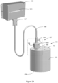
- Figures 1A and 1B show an ultrasonic probe 100 in accordance with an exemplary embodiment of the present invention. More specifically, Figure 1A shows an exploded perspective view of the ultrasonic probe 100 and Figure 1B shows a non-exploded sectional view of the ultrasonic probe 100 taken along line 1B-1B of Figure 1A . Dashed line 1D indicates a longitudinal axis of probe 100.
- the ultrasonic probe 100 comprises seal fitting members 102a and 102b, a flexible connector 104, a cable sheath 106, a neck tube 108 having a shoulder portion 113, and a barrel 123.
- the seal fitting members 102a and 102b are portions of a seal fitting assembly 157 that secures the ultrasonic probe 100 to a container 159.
- exemplary embodiments such as described in related co-pending U.S.
- the seal fitting assembly 157 is a face seal fitting assembly, where the seal fitting member 102a is a face seal fitting gland having a through hole 103 and the seal fitting member 102b is a standard sized face seal fitting having a three-quarter-inch (19.1 mm) hex nut.
- the seal fitting member 102b rests on a lip 149 of the seal fitting member 102a and can be rotated relative to the seal fitting member 102a about an axis drawn through the through hole 103.
- the seal fitting members 102a and 102b can have other dimensions and features, such as a longer gland, a half-inch (12.7 mm) or a non-standard size face seal fitting, and/or a seal fitting member 102b that is bonded to the seal fitting member 102a.
- other types of fittings can be used for seal fitting assembly 157, such as, for example, a surface mount C-seal.
- the seal fitting member 102a is coupled to the flexible connector 104 and the cable sheath 106.
- the neck tube 108 comprises an upper end 110 that defines an upper opening, a lower end 112 that defines a lower opening, and a sidewall 114.
- the shoulder portion 113 of the neck tube 108 comprises a shoulder tube 116 having an upper end 118 that defines an upper opening and a lower end 120 that defines a lower opening.
- the shoulder tube 116 is conical in shape and provides a smooth transition from the neck tube 108 to the outer tube 122 of the barrel 123.
- the lower end 112 of the neck tube 108 is disposed within the shoulder tube 116 and the shoulder tube 116 is coupled to the sidewall 114 of the neck tube 108.
- the entire neck tube 108, including the shoulder portion 113, can be formed of a single unitary part.
- the upper end 110 of the neck tube 108 is disposed within the through hole 103 of the seal fitting member 102a and within the flexible connector 104.
- the barrel 123 comprises an outer tube 122, an inner tube 132, and a disc cap 140.
- the outer tube 122 has an upper end 124 that defines an upper opening, a lower end 126 that defines a lower opening, a sidewall 128, and a through hole 130 disposed in the sidewall 128 near the upper end 124.
- the upper end 124 of the outer tube 122 is coupled to the lower end 120 of the shoulder tube 116.
- the inner tube 132 comprises an upper end 124 that defines an upper opening, a lower end 136 that defines a lower opening, and a sidewall 138.
- the upper end 134 defines an upper opening that is approximately perpendicular to the lower opening defined by the lower end 136.
- the inner tube 132 defines a conduit 144 (see Figure 1B ).
- the conduit may not be fully enclosed, as is the case with ultrasonic probe 100.
- the conduit could comprise a space located between the two spaced-apart members.
- the disc cap 140 comprises an inner rim 142 that defines an opening.
- the entirety of the inner tube 132 is disposed within the outer tube 122, the upper end 134 of the inner tube 132 is aligned with the through hole 130 disposed in the sidewall 128, and the lower end 136 of the inner tube 132 is aligned with the lower end 126 of the outer tube 122.
- the upper end 134 of the inner tube 132 is coupled to the sidewall 128.
- the disc cap 140 is coupled to the lower end 126 of the outer tube 122 and the lower end 136 of the inner tube 132, thereby coupling the lower end 126 of the outer tube 122 to the lower end 136 of the inner tube 132.
- the conduit 144 is disposed within the barrel 123 and has a lower opening defined by the lower end 136 of the inner tube 132 (the lower opening can also be regarded as being defined by the inner rim 142 of the disc cap 140) (see Figure 1B ).
- the conduit 144 is in flow communication with the internal volume of the container that holds liquid such that the liquid can flow through the conduit 144.
- the sidewall 128 of the outer tube 122 and the sidewall 138 of the inner tube 132 define an internal volume 146 (i.e., a compartment) therebetween that is also bounded by the disc cap 140, as shown.
- the internal volume 146 is isolated from the conduit 144 (i.e., the internal volume 146 is not in flow communication with the conduit 144 ) such that any liquid flowing through the conduit 144 cannot enter the internal volume 146.
- a plurality of ultrasonic sensors 156 is disposed within the internal volume 146 of the barrel 123.
- the plurality of ultrasonic sensors 156 includes twelve (12) ultrasonic sensors 156a through 156l that are coupled to the sidewall 138 of the inner tube 132.
- each of the plurality of ultrasonic sensors 156a through 156l are bonded to sidewall 138 with an epoxy.
- ultrasonic sensors 156a through 156l are oriented to emit sound waves in the direction facing sidewall 138 (e.g., perpendicular to longitudinal axis 1D ).
- Other suitable means for coupling can also be used, such as double-sided tape or other adhesives.
- the plurality of ultrasonic sensors 156 can include a greater or lesser number of sensors.
- the plurality of ultrasonic sensors 156 includes at least 5 ultrasonic sensors.
- the plurality of ultrasonic sensors 156 might be implemented with any suitable ultrasonic sensors that are known to those of ordinary skill in the art, such as, for example, piezoelectric crystals.
- Each ultrasonic sensor of the plurality of ultrasonic sensors 156a through 156l is oriented to emit sound waves through the sidewall 138 and the conduit 144 (and any liquid present therein) and detect the sound waves that are echoed back.
- Each ultrasonic sensor of the plurality of ultrasonic sensors 156a through 156l includes wiring 158 (comprising at least one wire) that extends from the internal volume 146, through the neck tube 108, and through the cable sheath 106.
- the wiring 158 is terminated at a connector 107 that is plugged into a controller 109 (see Figure 2 ).
- Controller 109 is a programmable data processing device that transmits electronic signals to the plurality of ultrasonic sensors 156, receives electronic signals from the plurality of ultrasonic sensors 156, and determines the level of liquid within container 159 into which the ultrasonic probe 100 is inserted.
- controller 109 comprises one or more microprocessors (not shown), a power supply (not shown), at least one input/output port (not shown) to receive connector 107, and a light-emitting-diode (LED) meter or liquid crystal display (LCD) 111 that provides a visual indication of the amount of liquid within the container.
- LED light-emitting-diode
- LCD liquid crystal display
- controller 109 can include other input/output ports and/or other aural and visual mechanisms for indicating the level of liquid within the container.
- controller 109 may be implemented with any type of programmable data processing device, including a personal computer executing control software.
- controller 109 For each ultrasonic sensor of the plurality of ultrasonic sensors 156, controller 109 transmits an electronic signal (e.g., one or more electronic pulses) to the ultrasonic sensor via the wiring 158, which causes the ultrasonic sensor to emit sound waves (i.e., the piezoelectric crystal oscillates). The ultrasonic sensor then receives echoed sound waves and converts the echoed waves into an electronic signal that is transmitted back to controller 109 via wiring 158. In a preferred embodiment, controller 109 transmits a series of multiple pulses (e.g., 20 pulses) to an individual one of the ultrasonic sensors 156, which emits sound waves corresponding to the pulses.
- an electronic signal e.g., one or more electronic pulses
- the ultrasonic sensor receives echoed sound waves and converts the echoed waves into an electronic signal that is transmitted back to controller 109 via wiring 158.
- controller 109 transmits a series of multiple pulses (e.g., 20 pulses) to an
- Controller 109 waits for a predetermined time period (e.g., a time window) to allow the ultrasonic sensor to receive any echoed waves returning from the emitted sound waves. If an echoed wave is received by the ultrasonic sensor, the sensor generates a signal that is transmitted to controller 109 (e.g., the piezoelectric crystal oscillates at a frequency and intensity based on the frequency and intensity of the received echoed waves). Based on whether any echoed waves are received in the time window (e.g., based on the frequency and/or intensity of any signal generated by the ultrasonic sensor), controller 109 determines whether liquid is present in conduit 144 at the given ultrasonic sensor.
- a predetermined time period e.g., a time window
- controller 109 transmits a series of multiple pulses to a next one of the ultrasonic sensors to sense the presence of liquid at a next level of ultrasonic probe 100.
- controller 109 interprets the intensity of the received signal as well as the time that elapsed between sending the electronic signal to the ultrasonic sensor and receiving the electronic signal from the ultrasonic sensor to determine whether there is liquid at the portion of conduit 144 at which that particular sensor is disposed. Accordingly, by using the plurality of ultrasonic sensors 156, the controller 109 can determine the level of liquid along the length of the conduit 144 and therefore the amount of liquid within the container into which the barrel 123 is inserted. Each sensor of the plurality of ultrasonic sensors 156 might be represented by an LED in the LED meter 111 to provide a visual indication of the amount of liquid within the container (e.g., each LED is illuminated only when liquid is detected by a particular sensor).
- the distance, D5 between disc cap 140 (e.g., the bottom end of ultrasonic probe 100) and the inner surface 178 of the base 179 of container 159 is a non-zero value to allow liquid to flow into conduit 144 to be measured by ultrasonic probe 100
- the bottom ultrasonic sensor e.g., ultrasonic sensor 156l
- the plurality of ultrasonic sensors 156 that is oriented to emit sound waves through the sidewall 138 and the conduit 144 will be some distance above the inner surface 178 of the base of the container. Therefore, ultrasonic probe 100 will have some inherent inaccuracy in measuring the precise level of the liquid within container 159.
- ultrasonic probe 100 might employ an ultrasonic sensor oriented to emit sound waves through disc cap 140 to the base of container 159 to determine the level of liquid present in the space, D5, between disc cap 140 (e.g., the bottom end of ultrasonic probe 100) and inner surface 178 of the base 179 of container 159 such as described in related copending U.S. Provisional Patent Application No. 62/043668, filed August 29, 2014 .
- the controller 109 can be programmed to transmit signals to, and receive signals from, less than all of the ultrasonic sensors 156a through 156l of the plurality of ultrasonic sensors 156 at the same time. This feature eliminates the need for the wiring 158 for the plurality of ultrasonic sensors 156 to be individually shielded and also allows the ultrasonic sensors 156a through 156l to be disposed closer together. In prior art systems, the wiring that connects the ultrasonic sensors to a controller is typically individually shielded to protect against interference (i.e., crosstalk) that results from electronic signals being transmitted to and from all of the ultrasonic sensors in the probe at the same time.
- interference i.e., crosstalk
- the wiring for each ultrasonic sensor in a typical prior art design may include a coaxial cable in which the inner conductor serves as the signal line to the ultrasonic sensor and the outer shield serves as the ground (e.g., grounded to a steel tube of the probe) and the signal return from the ultrasonic sensor.
- the ultrasonic sensors within the probe must also be spaced father apart to avoid interference that results from the ultrasonic sensors simultaneously emitting sound waves.
- Each of these characteristics i.e., added bulk from multiple shielded cables and greater spacing between sensors limits the number of ultrasonic sensors that can be disposed in a probe without increasing the size of the probe and related hardware.
- controller 109 is programmed or otherwise operatively configured to transmit signals to, and receive signals from, one ultrasonic sensor of the plurality of ultrasonic sensors 156 at a time.
- controller 109 can be programmed to first transmit an electronic signal to the ultrasonic sensor 156a and await receipt of the return signal from the ultrasonic sensor 156a, then transmit an electronic signal to the ultrasonic sensor 156b and await receipt of the return signal from the ultrasonic sensor 156b, and so on for each ultrasonic sensor of the plurality of ultrasonic sensors 156.
- the controller 109 Upon having transmitted an electronic signal to, and received an electronic signal from, each of the plurality of ultrasonic sensors 156 a first time (for example, beginning with ultrasonic sensor 156a and ending with ultrasonic sensor 156l , although other orders are possible), the controller 109 repeats the sequence and transmits an electronic signal to, and receives an electronic signal from, the ultrasonic sensor 156a and each of the plurality of ultrasonic sensors 156 a second time, and so on for as long as the ultrasonic probe 100 is being operated.
- the potential for interference between the wiring 158 for each ultrasonic sensor 156a through 156l and between the ultrasonic sensors themselves is greatly reduced or eliminated because the ultrasonic sensors 156a through 156l are not all simultaneously emitting or receiving sound waves and the wiring 158 for each of the ultrasonic sensors 156a through 156l is not simultaneously carrying electronic signals.
- This method of operating the plurality of ultrasonic sensors 156 eliminates the need for the wiring 158 for each ultrasonic sensor 156a through 156l to be individually shielded and the ultrasonic sensors 156a through 156l can be disposed closer together (i.e., even closer than is shown in Figure 1B ) than in prior art systems, both of which enable a greater number of ultrasonic sensors to be disposed within the barrel 123.
- the wiring 158 comprises a multi conductor shielded cable having a plurality of inner conductors that are not individually shielded, where a separate inner conductor is connected to each ultrasonic sensor of the plurality of ultrasonic sensors 156 to serve as the signal line, and an outer shield of the multi conductor shielded cable serves as a common return line and ground for all of the ultrasonic sensors of the plurality of ultrasonic sensors 156.
- a coaxial cable can be used as the multi conductor shielded cable, where the inner conductors are connected to the plurality of ultrasonic sensors 156 to serve as the signal lines, and the outer shield of the coaxial cable serves as the common return line.
- the multi-conductor shielded cable is a commercially available cable such as a model 83562 cable manufactured by Belden, Inc. of St. Louis, Missouri, USA.
- the neck tube 108 is disposed within the seal fitting members 102a and 102b and the flexible connector 104.
- the neck tube 108 is secured to the seal fitting member 102a by a fusion weld (i.e., a bead) made within the weld zone 148.
- a fusion weld i.e., a bead
- the weld occupies only a portion of the weld zone 148 and is made where the sidewall 114 of the neck tube 108 abuts the seal fitting member 102a.
- the seal fitting member 102a includes a protruding sealing surface (i.e., a seal face) 150 that extends around the neck tube 108.
- the protruding sealing surface 150 has an inner edge 151 that is separated from the sidewall 114 of the neck tube 108 by a distance D1.
- distance D1 is preferably at least 2.0 mm and, more preferably, at least 6.0 mm.
- the seal fitting member 102b includes a threaded region 152 that engages an opposite threaded region 166 of another seal fitting member 164 of the seal fitting assembly 157.
- Ultrasonic probe 100 might also include testing ports (not shown) used for leak detection when the ultrasonic probe 100 is secured to the container 159.
- the barrel 123 has an outer diameter D3 (i.e., the outer diameter of the outer tube 122 ).
- the neck tube 108 and the inner tube 132 have an outer diameter D2 that is less than the outer diameter D3 of the barrel 123.
- the larger outer diameter D3 of the barrel 123 relative to the outer diameter D2 of the inner tube 132 provides an increased amount of space within the internal volume 146 that is necessary to house the increased number of ultrasonic sensors 156a through 156l and their respective wiring 158.
- the ratio of the outer diameter D2 of the inner tube 132 to the outer diameter D3 of the barrel 123 is less than or equal to 0.95.
- the ratio of the outer diameter D2 of the inner tube 132 to the outer diameter D3 of the barrel 123 is less than or equal to 0.95 and greater than or equal to 0.3. More preferably, the ratio of the outer diameter D2 of the inner tube 132 to the outer diameter D3 of the barrel 123 is less than or equal to 0.8, and the outer diameter D3 of the barrel 123 is no greater than 0.827 inches (21.0 mm). More preferably, the ratio of the outer diameter D2 of the inner tube 132 to the outer diameter D3 of the barrel 123 is less than or equal to 0.8 and greater than or equal to 0.4.
- the outer diameter D2 of the inner tube 132 is approximately five-sixteenths of an inch (7.9 mm), and the outer diameter D3 of the barrel 123 is approximately five-eighths of an inch (15.9 mm).
- ultrasonic probe 100 might employ different constructions of neck tube 108 and barrel 123.
- shoulder portion 113 of neck tube 108 is formed by sidewall 114 rather than as a separate piece and is integral with the remainder of the neck tube 108 (i.e., the neck tube 108 and shoulder portion 113 are a single piece of material), for example by shoulder portion 113 having a bell shape that transitions from the outer diameter D2 of neck tube 108 to the outer diameter D3 of neck tube 108, which is also the outer diameter of barrel 123.
- this feature is advantageous because most of the components of the barrel 123 can be welded together prior to installing the plurality of ultrasonic sensors 156, where the heat from welding might otherwise damage the plurality of ultrasonic sensors 156 and/or the bonds which hold the plurality of ultrasonic sensors 156 in place within the internal volume 146.
- FIG 2A shows a perspective view of the ultrasonic probe 100 installed on a container 159 in accordance with an exemplary embodiment of the present invention.
- the ultrasonic probe 100 includes the controller 109 and the LED meter 111, as previously discussed.
- the container 159 comprises a body 160, an upper portion 162, and a seal fitting member 164 coupled to the upper portion 162.
- the container 159 may include other components that are not shown in Figure 2 for clarity and illustrative purposes (e.g., additional valves and hardware for refilling the container 159).
- the body 160 and upper portion 162 define an internal volume that can contain fluid.
- the upper portion 162 is a lid coupled to the body 160.
- the upper portion 162 can be an integral part of the body 160.
- the seal fitting member 164 like the seal fitting members 102a and 102b, is a portion of the seal fitting assembly 157 that secures the ultrasonic probe 100 to the container 159.
- the components of the container 159 are composed of one or more metals.
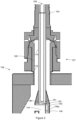
- Figure 2B shows a cross sectional view of the portion ultrasonic probe 100 and container 159 within the dashed box of Figure 2A , taken along line 2B-2B.
- stem 168 is disposed in a hole in the upper portion 162 of body 160 of container 159.
- stem 168 is a face seal fitting gland that is bonded (e.g., welded) to the upper portion 162 of body 160.
- Stem 168 comprises a protruding sealing surface 170, a lip 172, and a sidewall 174.
- Sidewall 174 of stem 168 has an inner diameter D4 that is greater than the outer diameter D3 of barrel 123 such that barrel 123 can be inserted into stem 168.
- Seal fitting member 164 is disposed around the stem 168 and comprises a threaded region 166 that engages the threaded region 152 of the seal fitting member 102b (i.e., the threaded regions 152 and 166 have complimentary threading such as female and male threading, respectively).
- a metal gasket 176 having a through hole is disposed between the protruding sealing surface 150 of the seal fitting member 102a and the protruding sealing surface 170 of the stem 168.
- barrel 123 is inserted through metal gasket 176 and stem 168 such that the barrel is disposed inside of container 159 and the neck tube is disposed within stem 168 and metal gasket 176.
- the threaded region 152 of the seal fitting member 102b is then threaded onto the threaded region 166 of the seal fitting member 164 such that the seal fitting member 102b engages (i.e., presses against) the lip 149 of the seal fitting member 102a, the seal fitting member 164 engages the lip 172 of the stem 168, and the metal gasket 176 is compressed between the protruding sealing surface 150 of the seal fitting member 102a and the protruding sealing surface 170 of the stem 168.
- the protruding sealing surface 170, the protruding sealing surface 150, and the metal gasket 176 form a metal-on-metal seal that prevents fluid (i.e., liquid, vapor, and/or gas) from escaping or entering the container 159.
- fluid i.e., liquid, vapor, and/or gas
- a distance S1 exists between the sidewall 114 of neck tube 108 and sidewall 174 of stem 168; a distance S2 exists between the upper portion 162 (i.e., lid) of the container 159 and the upper end 118 of shoulder tube 116, and the upper end 118 of the shoulder tube 116 is located below the lower-most portion of the stem 168; and a distance S3 exists between the upper portion 162 of container 159 and the upper end 124 of outer tube 122 of barrel 123.
- the distance S2 is greater than or equal to 0.10 inches (2.5 mm) and the distance S1 is greater than or equal to 0.70 mm.
- the distances S1, S2 and S3 are preferably large enough to allow fluid to travel in between sidewall 114 of neck tube 108 and sidewall 174 of the stem 168, but also drain back down and return into container 159 under the force of gravity. Stated differently, the distances S1, S2 and S3 are preferably large enough to avoid capillary action in which fluid is retained between sidewall 114 of neck tube 108 and sidewall 174 of stem 168. Avoiding such capillary action helps maximize the usable quantity of chemical reagent that can be drawn out of container 159 for use, and also ensures that during cleaning of container 159 and ultrasonic probe 100 in the fully installed configuration, no residual chemicals are left behind to potentially contaminate fresh chemical reagent that is later added to container 159.
- the described embodiments of an ultrasonic probe satisfy a need in the art for an ultrasonic probe having increased quantities of ultrasonic sensors that can be used with existing container fittings having standardized dimensions.
- the barrel 123 has an outer diameter D3 that provides an increased amount of space within the internal volume 146 that is necessary to house the increased number of ultrasonic sensors 156a through 156l and their respective wiring 158.
- the barrel typically extends into the seal fitting assembly.
- An increased outer diameter of the barrel would therefore require a larger and/or non-standard seal fitting assembly, or modifying a standard seal fitting assembly such as by boring out a through hole (e.g., through hole 103 of the seal fitting member 102a ) so it can receive the larger barrel diameter.
- non-standard fitting assemblies are typically much more expensive than their standardized counterparts and may also require the use of other non-standardized components.
- Non-standard fitting assemblies also do not benefit from the extensive testing and proven history of standardized fitting assemblies for use in semiconductor manufacturing processes. Larger seal fittings also require more space on the lid of the container (e.g., upper portion 162 ) and can make obtaining a tight seal more difficult.
- the inventors have found that attempts to modify standard seal fitting assemblies to receive a larger barrel diameter can negatively affect the structural integrity of the ultrasonic probe and/or the seal fitting assembly.
- the barrel 123 of the ultrasonic probe 100 does not extend into the seal fitting member 102a. Instead, the barrel 123 is coupled to the neck tube 108, which is in turn coupled to the seal fitting member 102a.
- the stem 168 is bored out such that the inner diameter D4 of the stem 168 is greater than the outer diameter D3 of the barrel 123 and the barrel 123 can be inserted into the stem 168.
- the neck tube 108 has an outer diameter D2 that is less than the outer diameter D3 of the barrel 123 (i.e., the ratio of D2 to D3 is less than one), which enables the through hole 103 of the seal fitting members 102a to have a smaller bore size, as opposed to requiring a larger seal fitting (e.g., a 1 inch seal fitting) or boring out the through hole 103 in the seal fitting member 102a to accommodate the increased outer diameter D3 of the barrel 123.
- the smaller outer diameter D2 of the neck tube 108 also provides the necessary distance D1 to have a sufficiently large weld zone 148 such that the neck tube 108 and the seal fitting member 102a can be welded together without welding material and/or welding heat impairing the protruding sealing surface 150. Preventing such damage to the protruding sealing surface 150 is critical to maintaining the integrity of the seal between the protruding sealing surface 150 and the metal gasket 176, and therefore maintaining the assay (purity) of the chemical reagent for use in semiconductor
- FIG 3 shows additional detail of wiring 158 to the plurality of ultrasonic sensors 156.
- controller 109 sequentially transmits an electronic signal to one of the ultrasonic sensors 156 and awaits receipt of a return signal from the ultrasonic sensor.
- wiring 158 is a multi conductor shielded cable that includes a plurality of inner wires, shown as wires 181, 182, and 183, and an outer shield, shown as cable shield 180.
- wires 181, 182 and 183 are individually insulated (e.g., electrically isolated from each other) but are not individually shielded.
- wire 181 is connected as a signal line to ultrasonic sensor 156a.
- Wires 182 and 183 are connected as signal lines to subsequent ones of the plurality of ultrasonic sensors 156 (not shown in Figure 3 ).
- cable shield 180 is electrically connected to the sidewall 138 of inner tube 132. Since, as described herein, cable shield 180 is employed as a common return line for echo signals from all of the ultrasonic sensors 156 to return to controller 109, by electrically connecting cable shield 180 to sidewall 138, a common wire does not need to be provided to each ultrasonic sensor, rather, the common connection to each ultrasonic sensor can be electrically connected to sidewall 138.
- wiring 158 includes a 2 layer outer shield, where one of the shield layers is a common return and the other shield layer is ground.
- one of the shield layers is a common return and the other shield layer is ground.
- an inner shield layer is employed as the common return, and an outer shield layer is employed as the ground.
- controller 109 might sequentially pulse each of ultrasonic sensors 156 at a predetermined frequency. For example, in one embodiment, controller 109 pulses ultrasonic sensors 156 at a frequency of 100kHz, although other frequencies of operation are possible. Although the sequential pulsing of the ultrasonic sensors 156 could be in any order (e.g., top-to-bottom, bottom-to-top, or any other order), in one embodiment, controller 109 sequentially pulses the ultrasonic sensors from bottom-to-top of ultrasonic probe 100 (e.g., from ultrasonic sensor 1561 to ultrasonic sensor 156a ).
- controller 109 could optionally be programmed to expect that all sensors located physically above the “dry” sensor should also be “dry” (e.g., the liquid level within the container is below the level of the first "dry” ultrasonic sensor).
- controller 109 if a sensor above the expected liquid level (e.g., above a "dry” sensor) is returning a "wet” status (e.g., the sensor indicates the presence of liquid), an error condition might be reported by controller 109 (e.g., on LED display 111 ) such that an operator can verify the liquid level within the container to determine if ultrasonic probe 100 is malfunctioning.
- controller 109 operates LED display 111 to display a status corresponding to each ultrasonic sensor 156. For example, if a given one of ultrasonic sensors 156 is indicating that liquid is present ("wet"), the corresponding indicator of LED display 111 might be lit solidly. Similarly, if a given one of ultrasonic sensors 156 is indicating that liquid is not present (“dry”), the corresponding indicator of LED display 111 might be lit, but blinking. If controller 109 cannot communicate with ultrasonic probe 100, or the container is entirely empty of liquid, all of the indicators of LED display might blink.
- Ultrasonic probe 100 is employed to measure a level of liquid within a container that might be subject to splashing, churning, bubbling, vaporization/condensation or other physical disturbances that could temporarily alter the liquid level sensed by ultrasonic probe 100. Therefore, to limit fluctuation in the liquid level displayed on LED display 111, controller 109 might employ hysteresis and/or delay to more accurately report the liquid level within the container.
- controller 109 might delay a predetermined amount of time before changing a reading of a particular sensor from “wet” to “dry” (indicating a reduction in liquid level), which would allow controller 109 to receive multiple readings from the given ultrasonic sensor 156 before changing the liquid level indication, and hopefully avoiding any temporary disturbance in the liquid level of the container.
- controller 109 delays 5 seconds before changing a reading of a particular sensor from “wet” to “dry”. This means that, once the controller 109 receives a sensor reading of "dry” from a sensor that was previously reading "wet”, that sensor would have to read “dry” for 5 seconds before the controller 109 would change the LED display 111 to show that sensor as being dry. If, at any time during the 5 second period, that sensor read “wet”, the controller 109 would maintain a "wet” indication.
- controller 109 would not include a delay to indicate changing a reading of a particular sensor from “dry” to “wet” (indicating an increase in liquid level). This asymmetrical operation may be desirable in refill-in-place containers, where it may be advantageous to rapidly indicate increasing liquid levels in order to avoid overfilling the container. Alternatively, a shorter predetermined time delay (for example, 1 second) could be used when changing a reading of a particular sensor from "dry” to "wet”. In some embodiments, controller 109 might store previous readings of ultrasonic sensors 156 to employ hysteresis based upon one or more previous readings of the ultrasonic sensors.
- controller 109 might desirably communicate liquid level data to external devices, for example, a central computer located within the manufacturing facility, such that plant operators can monitor liquid levels of multiple containers remotely from a single location.
- controller 109 might provide a two wire output link for communication to external devices.
- controller 109 might provide a "stepped analog output" or quantized output, to communicate the liquid level within the container.
- a fixed voltage (or current) step might be output corresponding to each ultrasonic sensor 156.
- a first voltage (or current) might be output by controller 109.
- This voltage (or current) might be increased by a fixed step for each sensor above ultrasonic sensor 156l that senses liquid.
- the stepped analog output is 4-20mA across the 12 ultrasonic sensors 156.
- the stepped analog output is 0-10V across the 12 ultrasonic sensors 156, although other voltage or current ranges are possible (e.g., 0-5 volts, etc.).
- the type of the stepped analog output e.g., voltage or current
- a stepped analog current output might be less susceptible to noise that a stepped analog voltage output in some operating environments.
- Providing an output and configuring the controller 109 to generate a stepped analog output or digital output enables other components in the system in which the container 159 is used to receive information concerning fluid level in the container 159 with only a two-wire interface. This is an improvement over sensor probe systems of the prior art, in which it was common for the output to consist of at least one output signal wire for each of the ultrasonic sensors 156.
- FIG. 4 shows a block diagram of circuitry of controller 109.
- controller 109 includes microcontroller 186 and status display 111.
- status display 111 might be implemented as one or more LEDs, an LCD screen, or other display types suitable to display the liquid level within container 159.
- Ultrasonic probe 100 is in electrical communication with microcontroller 186, for example, by cable 106 and wiring 158, to communicate electronic signals between ultrasonic sensors 156 and microcontroller 186.
- Microcontroller 186 processes signals received from ultrasonic probe to determine a liquid level of container 159.
- Microcontroller 186 controls status display 111 to display an indication based on the determined liquid level.
- microcontroller 186 is electrically coupled, for example via signal output 192 and cable 190, to one or more external control devices 188.
- External control devices 188 might be a database or monitoring application on a computer or server of the manufacturing facility or might be a control unit of specific manufacturing equipment.
- cable 190 might be a two-conductor cable, and microcontroller 186 might communicate over the two-conductor cable via a "stepped analog output" or quantized output corresponding to the determined level of liquid in container 159 via ultrasonic probe 100.
- the stepped analog output current might be as shown in Table 1 below: Table 1 Highest "Wet” Sensor Stepped Analog Output Current (mA) none 4.0 156l 5.3 156k 6.7 156j 8.0 156i 9.3 156h 10.7 156g 12.0 156f 13.3 156e 14.7 156d 16.0 156c 17.3 156b 18.7 156a 20.0
- controller 109 might provide a standardized communication link (such as Ethernet) to link controller 109 to other computers, servers or controllers within the manufacturing facility to enable remote monitoring of liquid levels in one or more containers.
- controller 109 might simply communicate an estimated liquid level within the container, might report which ones of ultrasonic sensors 156 are sensing liquid, might report the status of each of ultrasonic sensors 156, or some combination thereof.
- microcontroller 186 might be in communication with a communication module to provide data in the format of the standardized communications link (e.g., an Ethernet communications module to format data from microcontroller 186 into Ethernet data packets).
Landscapes
- Physics & Mathematics (AREA)
- General Physics & Mathematics (AREA)
- Acoustics & Sound (AREA)
- Electromagnetism (AREA)
- Thermal Sciences (AREA)
- Fluid Mechanics (AREA)
- Health & Medical Sciences (AREA)
- Life Sciences & Earth Sciences (AREA)
- Chemical & Material Sciences (AREA)
- Analytical Chemistry (AREA)
- Biochemistry (AREA)
- General Health & Medical Sciences (AREA)
- Immunology (AREA)
- Pathology (AREA)
- Measurement Of Levels Of Liquids Or Fluent Solid Materials (AREA)
Claims (12)
- Verfahren zum Bestimmen und Anzeigen eines Fluidfüllstands eines Fluids in einem Behälter (159) mittels einer Sonde (100), die in dem Behälter (159) positioniert ist, wobei die Sonde (100) eine Mehrzahl von Ultraschallsensoren (156) aufweist, die sich in einer Trommel (123) befinden, wobei sich jeder der Mehrzahl von Ultraschallsensoren (156) an einem unterschiedlichen Fluidfüllstand in dem Behälter (159) befindet, wobei das Verfahren umfasst:(a) Senden eines elektrischen Impulses an einen ersten Sensor (156a) der Mehrzahl von Ultraschallsensoren (156);(b) Empfangen eines elektrischen Signals von dem ersten Sensor (156a) als Reaktion auf den in Schritt (a) gesendeten elektrischen Impuls;(c) Durchführen von Schritt (a) an jedem der Mehrzahl von Ultraschallsensoren (156) in einer ersten Sequenz;(d) Wiederholen von Schritt (a) auf einer ersten Frequenz;(e) Bestimmen eines Zustands des ersten Sensors (156a) für jede Durchführung von Schritt (a) auf der ersten Frequenz auf der Grundlage von mindestens einem elektrischen Signal von dem ersten Sensor (156a), das in Schritt (b) empfangen wird, wobei der Zustand ausgewählt ist aus der Gruppe von: Trockenzustand, Feuchtzustand und wahlweise Fehlerzustand, wobei der Feuchtzustand eine Abwesenheit des Fluids an dem Fluidfüllstand anzeigt, an dem sich der erste Sensor (156a) befindet, wobei der Trockenzustand eine Abwesenheit des Fluids an dem Fluidfüllstand anzeigt, an dem sich der erste Sensor (156a) befindet;(f) Ändern des Zustands des ersten Sensors (156a), der in Schritt (e) bestimmt wird, auf einen unterschiedlichen Zustand als bei einer unmittelbar vorhergehenden Durchführung von Schritt (e) bestimmt wurde, nur dann, wenn mindestens eine vorbestimmte Bedingung erfüllt ist;(g) Durchführen von Schritt (e) und (f) an jedem der Mehrzahl von Ultraschallsensoren (156);(h) Wiederholen von Schritt (g); und(i) Anzeigen einer visuellen Indikation des Zustands von jedem der Mehrzahl von Ultraschallsensoren, der in Schritt (e) bis (g) bestimmt wurde,dadurch gekennzeichnet, dass die Sonde (100) umfasst:ein abgeschirmtes Mehrleiterkabel (158), umfassend eine zweischichtige Außenabschirmung und eine Mehrzahl von Leitern (181, 182, 183), wobei jeder der Mehrzahl von Leitern (181, 182, 183) einzeln isoliert, aber nicht einzeln abgeschirmt ist;wobei jeder Ultraschallsensor der Mehrzahl von Ultraschallsensoren (156) mit einem gesonderten der Mehrzahl von Leitern (181, 182, 183) und mit einer ersten Schicht der Außenabschirmung zur gemeinsamen Signalrückführung elektrisch verbunden ist, und wobei eine zweite Schicht der Außenabschirmung zur Erdung verwendet wird.
- Verfahren nach Anspruch 1, wobei die mindestens eine vorbestimmte Bedingung ein Empfangen einer Mehrzahl von elektrischen Signalen von dem ersten Sensor (156a) während sequenzieller Durchführungen von Schritt (b) an dem ersten Sensor (156a), die alle den gleichen Zustand anzeigen, umfasst.
- Verfahren nach Anspruch 1, wobei die mindestens eine vorbestimmte Bedingung ein Empfangen einer Mehrzahl von elektrischen Signalen von dem ersten Sensor (156a) während sequenzieller Durchführungen von Schritt (b) an dem ersten Sensor (156a) über einen vorbestimmten Zeitraum, die alle den gleichen Zustand anzeigen, umfasst.
- Verfahren nach Anspruch 3, wobei der vorbestimmte Zeitraum ein erster vorbestimmter Zeitraum ist, wenn sich der Zustand des ersten Sensors (156a) von einem Feuchtzustand auf einen Trockenzustand ändert, und ein zweiter vorbestimmter Zeitraum, wenn sich der Zustand des ersten Sensors (156a) von einem Trockenzustand auf einen Feuchtzustand ändert, wobei der erste vorbestimmte Zeitraum länger als der zweite vorbestimmte Zeitraum ist.
- Verfahren nach Anspruch 1, ferner umfassend ein Durchführen von Schritt (f) nur dann, wenn die Änderung des Zustands des ersten Sensors (156a) von einem Feuchtzustand auf einen Trockenzustand erfolgt.
- Verfahren nach Anspruch 3, wobei der vorbestimmte Zeitraum mindestens fünf Sekunden beträgt.
- Verfahren nach Anspruch 1, wobei Schritt (f) ein Bestimmen des Zustands des ersten Sensors (156a) als Fehlerzustand umfasst, wenn das elektrische Signal von dem ersten Sensor (156a), das in Schritt (b) empfangen wird, einen Trockenzustand anzeigt und einer der Mehrzahl von Sensoren (156), die sich an einem Fluidfüllstand oberhalb des ersten Sensors (156a) befinden, als aktuell in einem Feuchtzustand befindlich bestimmt wird.
- System zur Bestimmung des Füllstands eines Fluids in einem Behälter (159), wobei das System umfasst:eine Steuerung (109);eine Ultraschallsonde (100), umfassend eine zum Befestigen an dem Behälter (159) ausgelegte Montageanordnung (157), eine sich von der Montageanordnung (157) nach unten erstreckende Trommel (123) und eine sich in der Trommel (123) befindende Mehrzahl von Ultraschallsensoren (156), wobei sich jeder der Mehrzahl von Ultraschallsensoren (156) im Gebrauch an einem unterschiedlichen Fluidfüllstand in dem Behälter (159) befindet, wobei jeder der Mehrzahl von Ultraschallsensoren (156) mit der Steuerung (109) elektrisch verbunden ist und dafür ausgelegt ist, von der Steuerung (109) gesendete elektronische Signale zu empfangen, Schallwellen als Reaktion auf die von der Steuerung (109) gesendeten elektronischen Signale auszugeben, Schallwellen zu erfassen und elektronische Signale an die Steuerung (109) zu übertragen, die die erfassten Schallwellen anzeigen, wobei die Ultraschallsonde (100) derart geformt und konfiguriert ist, dass sie in den Behälter (159) eingeführt wird; wobei die Steuerung (109) betriebsfähig dafür konfiguriert ist, in einer ersten Sequenz elektrische Impulse auf einer ersten Frequenz zu senden und die elektrischen Impulse auf jeden der Mehrzahl von Ultraschallsensoren (156) zu richten;wobei die Ultraschallsonde (100) ein abgeschirmtes Mehrleiterkabel (158) umfasst, umfassend eine zweischichtige Außenabschirmung und eine Mehrzahl von Leitern (181, 182, 183), wobei jeder der Mehrzahl von Leitern (181, 182, 183) einzeln isoliert, aber nicht einzeln abgeschirmt ist;wobei jeder Ultraschallsensor (156) der Mehrzahl von Ultraschallsensoren (156) mit einem gesonderten der Mehrzahl von Leitern (181, 182, 183) und mit einer ersten Schicht der Außenabschirmung zur gemeinsamen Signalrückführung elektrisch verbunden ist, und wobei eine zweite Schicht der Außenabschirmung zur Erdung verwendet wird;
und(a) wobei das System ferner eine Anzeige (111) umfasst, die mit der Steuerung (109) elektrisch verbunden ist;wobei die Steuerung (109) betriebsfähig dafür konfiguriert ist, einen Zustand von jedem der Mehrzahl von Ultraschallsensoren (156) auf der Grundlage der übertragenen elektronischen Signale von jedem der Mehrzahl von Ultraschallsensoren (156) zu bestimmen, wobei der Zustand einen Trockenzustand und einen Feuchtzustand anzeigt, wobei der Feuchtzustand bedeutet, dass das übertragene elektronische Signal, das von einem Sensor der Mehrzahl von Ultraschallsensoren (156) empfangen wird, anzeigt, dass ein Fluidfüllstand in dem Behälter (159) an oder oberhalb der Position jenes Sensors (156) liegt, wobei der Trockenzustand bedeutet, dass das übertragene elektronische Signal, das von einem Sensor der Mehrzahl von Ultraschallsensoren (156) empfangen wird, anzeigt, dass ein Fluidfüllstand in dem Behälter (159) unterhalb der Position jenes Sensors (156) liegt;wobei die Steuerung (109) betriebsfähig dafür konfiguriert ist, die Anzeige (111) zu veranlassen, eine visuelle Indikation eines Trockenzustands oder Feuchtzustands für jeden der Mehrzahl von Ultraschallsensoren (156) bereitzustellen;wobei die Steuerung (109) betriebsfähig dafür konfiguriert ist, sequenzielle übertragene elektronische Signale von jedem der Mehrzahl von Ultraschallsensoren (156) zu vergleichen; undwobei die Steuerung (109) betriebsfähig dafür konfiguriert ist, die visuelle Indikation für einen der Mehrzahl von Ultraschallsensoren (156) nur dann von einem Feuchtzustand auf einen Trockenzustand zu ändern, wenn mindestens ein vorbestimmtes Kriterium erfüllt ist;
(b) wobei die Steuerung (109) betriebsfähig dafür konfiguriert ist, elektronische Signale von jedem der Mehrzahl von Ultraschallsensoren (156) auf einer ersten Frequenz zu empfangen und sequenzielle übertragene elektronische Signale von jedem der Mehrzahl von Ultraschallsensoren (156) zu vergleichen;wobei die Steuerung (109) betriebsfähig dafür konfiguriert ist, einen Fluidfüllstand in dem Behälter (159) auf der Grundlage der übertragenen elektronischen Signale von jedem der Mehrzahl von Ultraschallsensoren (156) zu bestimmen; undwobei die Steuerung (109) betriebsfähig dafür konfiguriert ist, ein Ausgangssignal für die Kommunikation mit einer oder mehreren externen Vorrichtungen (188) zu erzeugen, die mit der Steuerung (109) in elektrischer Kommunikation stehen, wobei das Ausgangssignal für den Fluidfüllstand in dem Behälter (159) steht, der durch die Steuerung (109) bestimmt wird. - System nach Anspruch 8(a), wobei das mindestens eine vorbestimmte Kriterium umfasst, dass alle Übertragungen von elektronischen Signalen von dem einen der Mehrzahl von Ultraschallsensoren (156) während eines vorbestimmten Zeitraums einen Trockenzustand für jenen der Mehrzahl von Ultraschallsensoren (156) anzeigen, wobei der vorbestimmte Zeitraum lang genug ist, um das Senden einer Mehrzahl von elektrischen Impulsen von der Steuerung (109) an den einen der Mehrzahl von Ultraschallsensoren (156) während des vorbestimmten Zeitraums zu gestatten.
- System nach Anspruch 8(a), wobei der Zustand ferner einen Fehlerzustand einschließt, und wobei die Steuerung (109) betriebsfähig dafür konfiguriert ist, die visuelle Indikation für einen der Mehrzahl von Ultraschallsensoren (156) von einem Trockenzustand auf einen Fehlerzustand zu ändern, wenn der Zustand von einem der Mehrzahl von Ultraschallsensoren (156), die sich oberhalb des einen der Mehrzahl von Ultraschallsensoren (156) befinden, ein Feuchtzustand ist.
- System nach Anspruch 8(a), wobei die Trommel (123) umfasst:ein Außenrohr (122) mit einer oberen Öffnung (124), einer unteren Öffnung (126), einer Seitenwand (128) und einer in der Seitenwand (128) angeordneten Seitenöffnung (130); undein Innenrohr (132), das mit dem Außenrohr (122) verbunden ist, wobei das Innenrohr (132) eine obere Öffnung (134), eine untere Öffnung (136) und eine Seitenwand (138) umfasst, wobei die obere Öffnung (134) des Innenrohrs auf die Seitenöffnung (130) des Außenrohrs (122) ausgerichtet ist, die untere Öffnung (136) des Innenrohrs (132) auf die untere Öffnung (126) des Außenrohrs (122) ausgerichtet ist, wobei das Innenrohr (132) die Leitung (144) definiert, wobei sich das Innenvolumen zwischen der Seitenwand (138) des Innenrohrs (132) und der Seitenwand (128) des Außenrohrs (122) befindet und sich zumindest ein Teil der Mehrzahl von Ultraschallsensoren (156) in dem Innenvolumen befindet.
- System nach Anspruch 8(b), wobei das Ausgangssignal ein gestufter analoger Ausgang ist,wobei der gestufte analoge Ausgang eine Stromstärke aufweist, wobei die Stromstärke direkt proportional zu dem Fluidfüllstand ist, oderwobei der gestufte analoge Ausgang eine Spannung aufweist, wobei die Spannung direkt proportional zu dem Fluidfüllstand ist; oderwobei das Ausgangssignal ein digitaler Ausgang ist, der direkt proportional zu dem Fluidfüllstand ist.
Applications Claiming Priority (2)
| Application Number | Priority Date | Filing Date | Title |
|---|---|---|---|
| US201462081266P | 2014-11-18 | 2014-11-18 | |
| PCT/US2015/061307 WO2016081581A1 (en) | 2014-11-18 | 2015-11-18 | Ultrasonic liquid level sensing systems |
Publications (3)
| Publication Number | Publication Date |
|---|---|
| EP3221671A1 EP3221671A1 (de) | 2017-09-27 |
| EP3221671A4 EP3221671A4 (de) | 2018-12-12 |
| EP3221671B1 true EP3221671B1 (de) | 2023-06-21 |
Family
ID=56014498
Family Applications (1)
| Application Number | Title | Priority Date | Filing Date |
|---|---|---|---|
| EP15860126.0A Active EP3221671B1 (de) | 2014-11-18 | 2015-11-18 | Ultraschall-flüssigkeitsstandmesssysteme |
Country Status (7)
| Country | Link |
|---|---|
| US (2) | US10809115B2 (de) |
| EP (1) | EP3221671B1 (de) |
| JP (1) | JP6702995B2 (de) |
| KR (2) | KR20190100444A (de) |
| CN (1) | CN106941778B (de) |
| TW (1) | TWI598573B (de) |
| WO (1) | WO2016081581A1 (de) |
Families Citing this family (4)
| Publication number | Priority date | Publication date | Assignee | Title |
|---|---|---|---|---|
| DE102015016775A1 (de) * | 2015-12-23 | 2017-06-29 | Audi Ag | Verfahren zum Betreiben einer Sensoranordnung für einen Fluidtank eines Kraftfahrzeugs sowie entsprechende Sensoranordnung |
| WO2020068710A1 (en) * | 2018-09-24 | 2020-04-02 | Molex, Llc | A system for monitoring a thickness of one or more assets using an ultrasonic measurement system, a multiplexer switch module and a two-conductor connection, and a method of performing the same |
| EP3870940B1 (de) | 2018-12-03 | 2023-10-18 | Bio-Rad Laboratories, Inc. | Flüssigkeitsstandbestimmung |
| TWI723757B (zh) * | 2019-08-30 | 2021-04-01 | 財團法人國家實驗研究院 | 液位監測系統及其方法 |
Family Cites Families (28)
| Publication number | Priority date | Publication date | Assignee | Title |
|---|---|---|---|---|
| US4077022A (en) * | 1974-08-05 | 1978-02-28 | Texaco Inc. | Well logging method and means using an armored multiconductor coaxial cable |
| US4063457A (en) * | 1976-09-27 | 1977-12-20 | Envirotech Corporation | Ultrasonic level sensing device |
| JPS574519A (en) * | 1980-06-11 | 1982-01-11 | Fueroo Kogyo Kk | Level measuring device |
| US4523472A (en) * | 1980-07-02 | 1985-06-18 | Purecycle Corporation | Ultrasonic transceiver circuit |
| JPS59155522U (ja) * | 1983-04-04 | 1984-10-18 | 株式会社 荏原電産 | 液位検出装置 |
| JPH0181526U (de) * | 1987-11-20 | 1989-05-31 | ||
| US5697248A (en) * | 1991-07-25 | 1997-12-16 | The Whitaker Corporation | Liquid level sensor |
| JPH05223619A (ja) * | 1992-02-10 | 1993-08-31 | Toyota Motor Corp | タンク内液量検出装置 |
| US5437178A (en) * | 1992-07-06 | 1995-08-01 | Kay-Ray/Sensall, Inc. | Controller for ultrasonic sensors |
| DE4405238C2 (de) * | 1994-02-18 | 1998-07-09 | Endress Hauser Gmbh Co | Anordnung zur Messung des Füllstands in einem Behälter |
| JPH08122128A (ja) * | 1994-10-24 | 1996-05-17 | Hitachi Ltd | 液面検出装置 |
| JP3524183B2 (ja) * | 1994-12-26 | 2004-05-10 | テルモ株式会社 | 超音波探触子 |
| JP2905728B2 (ja) * | 1995-09-19 | 1999-06-14 | 大和機工株式会社 | 生コンクリートの残量判定装置 |
| US5808200A (en) * | 1997-08-25 | 1998-09-15 | Cosense, Inc. | Ultrasonic sensor with continous and demand self-test for liquid and dry product level measurement |
| GB9915254D0 (en) | 1999-07-01 | 1999-09-01 | Smiths Industries Plc | Fluid-gauging systems and methods |
| CN2384205Y (zh) * | 1999-07-26 | 2000-06-21 | 谭锦林 | 一种远距传感容器液位的测显器 |
| JP2002148093A (ja) * | 2000-11-10 | 2002-05-22 | Miyairi Valve Seisakusho:Kk | 液面計およびバルク貯槽 |
| GB0118320D0 (en) * | 2001-07-27 | 2001-09-19 | Ici Plc | Level measurement |
| JP3768911B2 (ja) * | 2002-04-11 | 2006-04-19 | アロカ株式会社 | 超音波診断装置 |
| ATE490731T1 (de) * | 2005-01-18 | 2010-12-15 | Esaote Spa | Ultraschallsonde, insbesondere zur diagnostischen bilderzeugung |
| US20070074571A1 (en) * | 2005-10-03 | 2007-04-05 | Haynes Kevin M | Ultrasonic sensor self test |
| JP4910397B2 (ja) * | 2006-01-13 | 2012-04-04 | 住友電気工業株式会社 | 複合ケーブル及び複合ケーブル加工品 |
| JP2008203205A (ja) * | 2007-02-22 | 2008-09-04 | Ricoh Elemex Corp | 液体検知装置 |
| JP2009041991A (ja) * | 2007-08-07 | 2009-02-26 | Ricoh Elemex Corp | 可搬式液体検知ユニット |
| GB0722256D0 (en) * | 2007-11-13 | 2007-12-27 | Johnson Matthey Plc | Level measurement system |
| JP6150458B2 (ja) * | 2012-02-21 | 2017-06-21 | キヤノン株式会社 | 超音波装置 |
| CN102841389B (zh) * | 2012-09-04 | 2015-07-22 | 深圳市理邦精密仪器股份有限公司 | 一种气液分离器检测的方法及装置 |
| US9316525B2 (en) | 2013-05-15 | 2016-04-19 | Air Products And Chemicals, Inc. | Ultrasonic liquid level sensing systems |
-
2015
- 2015-11-18 EP EP15860126.0A patent/EP3221671B1/de active Active
- 2015-11-18 KR KR1020197024312A patent/KR20190100444A/ko not_active Withdrawn
- 2015-11-18 CN CN201580062453.XA patent/CN106941778B/zh active Active
- 2015-11-18 WO PCT/US2015/061307 patent/WO2016081581A1/en not_active Ceased
- 2015-11-18 KR KR1020177016718A patent/KR102014510B1/ko active Active
- 2015-11-18 JP JP2017545530A patent/JP6702995B2/ja active Active
- 2015-11-18 US US15/527,628 patent/US10809115B2/en active Active
- 2015-11-18 TW TW104138134A patent/TWI598573B/zh active
-
2020
- 2020-09-18 US US17/026,118 patent/US20210003442A1/en not_active Abandoned
Also Published As
| Publication number | Publication date |
|---|---|
| CN106941778A (zh) | 2017-07-11 |
| EP3221671A4 (de) | 2018-12-12 |
| US20180023994A1 (en) | 2018-01-25 |
| TWI598573B (zh) | 2017-09-11 |
| US10809115B2 (en) | 2020-10-20 |
| EP3221671A1 (de) | 2017-09-27 |
| JP6702995B2 (ja) | 2020-06-03 |
| KR20190100444A (ko) | 2019-08-28 |
| CN106941778B (zh) | 2021-03-26 |
| WO2016081581A1 (en) | 2016-05-26 |
| JP2017534893A (ja) | 2017-11-24 |
| US20210003442A1 (en) | 2021-01-07 |
| KR102014510B1 (ko) | 2019-08-26 |
| TW201621281A (zh) | 2016-06-16 |
| KR20170083632A (ko) | 2017-07-18 |
Similar Documents
| Publication | Publication Date | Title |
|---|---|---|
| US9550260B2 (en) | Ultrasonic liquid level sensing systems | |
| US10151618B2 (en) | Ultrasonic liquid level sensing systems | |
| US20210003442A1 (en) | Ultrasonic Liquid Level Sensing Systems | |
| US7610806B2 (en) | Electronic level gage assembly | |
| EP2803955B1 (de) | Ultraschall-Flüssigkeitsstandmesssysteme |
Legal Events
| Date | Code | Title | Description |
|---|---|---|---|
| STAA | Information on the status of an ep patent application or granted ep patent |
Free format text: STATUS: THE INTERNATIONAL PUBLICATION HAS BEEN MADE |
|
| PUAI | Public reference made under article 153(3) epc to a published international application that has entered the european phase |
Free format text: ORIGINAL CODE: 0009012 |
|
| STAA | Information on the status of an ep patent application or granted ep patent |
Free format text: STATUS: REQUEST FOR EXAMINATION WAS MADE |
|
| 17P | Request for examination filed |
Effective date: 20170616 |
|
| AK | Designated contracting states |
Kind code of ref document: A1 Designated state(s): AL AT BE BG CH CY CZ DE DK EE ES FI FR GB GR HR HU IE IS IT LI LT LU LV MC MK MT NL NO PL PT RO RS SE SI SK SM TR |
|
| AX | Request for extension of the european patent |
Extension state: BA ME |
|
| DAV | Request for validation of the european patent (deleted) | ||
| DAX | Request for extension of the european patent (deleted) | ||
| RIC1 | Information provided on ipc code assigned before grant |
Ipc: H01L 21/66 20060101ALI20180806BHEP Ipc: G01F 23/296 20060101AFI20180806BHEP |
|
| A4 | Supplementary search report drawn up and despatched |
Effective date: 20181112 |
|
| RIC1 | Information provided on ipc code assigned before grant |
Ipc: G01F 23/296 20060101AFI20181106BHEP Ipc: H01L 21/66 20060101ALI20181106BHEP |
|
| STAA | Information on the status of an ep patent application or granted ep patent |
Free format text: STATUS: EXAMINATION IS IN PROGRESS |
|
| 17Q | First examination report despatched |
Effective date: 20220223 |
|
| GRAP | Despatch of communication of intention to grant a patent |
Free format text: ORIGINAL CODE: EPIDOSNIGR1 |
|
| STAA | Information on the status of an ep patent application or granted ep patent |
Free format text: STATUS: GRANT OF PATENT IS INTENDED |
|
| INTG | Intention to grant announced |
Effective date: 20230315 |
|
| GRAS | Grant fee paid |
Free format text: ORIGINAL CODE: EPIDOSNIGR3 |
|
| GRAA | (expected) grant |
Free format text: ORIGINAL CODE: 0009210 |
|
| STAA | Information on the status of an ep patent application or granted ep patent |
Free format text: STATUS: THE PATENT HAS BEEN GRANTED |
|
| AK | Designated contracting states |
Kind code of ref document: B1 Designated state(s): AL AT BE BG CH CY CZ DE DK EE ES FI FR GB GR HR HU IE IS IT LI LT LU LV MC MK MT NL NO PL PT RO RS SE SI SK SM TR |
|
| REG | Reference to a national code |
Ref country code: CH Ref legal event code: EP |
|
| P01 | Opt-out of the competence of the unified patent court (upc) registered |
Effective date: 20230602 |
|
| REG | Reference to a national code |
Ref country code: DE Ref legal event code: R096 Ref document number: 602015084293 Country of ref document: DE |
|
| REG | Reference to a national code |
Ref country code: AT Ref legal event code: REF Ref document number: 1581199 Country of ref document: AT Kind code of ref document: T Effective date: 20230715 |
|
| REG | Reference to a national code |
Ref country code: IE Ref legal event code: FG4D |
|
| REG | Reference to a national code |
Ref country code: LT Ref legal event code: MG9D |
|
| REG | Reference to a national code |
Ref country code: NL Ref legal event code: MP Effective date: 20230621 |
|
| PG25 | Lapsed in a contracting state [announced via postgrant information from national office to epo] |
Ref country code: SE Free format text: LAPSE BECAUSE OF FAILURE TO SUBMIT A TRANSLATION OF THE DESCRIPTION OR TO PAY THE FEE WITHIN THE PRESCRIBED TIME-LIMIT Effective date: 20230621 Ref country code: NO Free format text: LAPSE BECAUSE OF FAILURE TO SUBMIT A TRANSLATION OF THE DESCRIPTION OR TO PAY THE FEE WITHIN THE PRESCRIBED TIME-LIMIT Effective date: 20230921 |
|
| REG | Reference to a national code |
Ref country code: AT Ref legal event code: MK05 Ref document number: 1581199 Country of ref document: AT Kind code of ref document: T Effective date: 20230621 |
|
| PG25 | Lapsed in a contracting state [announced via postgrant information from national office to epo] |
Ref country code: RS Free format text: LAPSE BECAUSE OF FAILURE TO SUBMIT A TRANSLATION OF THE DESCRIPTION OR TO PAY THE FEE WITHIN THE PRESCRIBED TIME-LIMIT Effective date: 20230621 Ref country code: NL Free format text: LAPSE BECAUSE OF FAILURE TO SUBMIT A TRANSLATION OF THE DESCRIPTION OR TO PAY THE FEE WITHIN THE PRESCRIBED TIME-LIMIT Effective date: 20230621 Ref country code: LV Free format text: LAPSE BECAUSE OF FAILURE TO SUBMIT A TRANSLATION OF THE DESCRIPTION OR TO PAY THE FEE WITHIN THE PRESCRIBED TIME-LIMIT Effective date: 20230621 Ref country code: LT Free format text: LAPSE BECAUSE OF FAILURE TO SUBMIT A TRANSLATION OF THE DESCRIPTION OR TO PAY THE FEE WITHIN THE PRESCRIBED TIME-LIMIT Effective date: 20230621 Ref country code: HR Free format text: LAPSE BECAUSE OF FAILURE TO SUBMIT A TRANSLATION OF THE DESCRIPTION OR TO PAY THE FEE WITHIN THE PRESCRIBED TIME-LIMIT Effective date: 20230621 Ref country code: GR Free format text: LAPSE BECAUSE OF FAILURE TO SUBMIT A TRANSLATION OF THE DESCRIPTION OR TO PAY THE FEE WITHIN THE PRESCRIBED TIME-LIMIT Effective date: 20230922 |
|
| PG25 | Lapsed in a contracting state [announced via postgrant information from national office to epo] |
Ref country code: FI Free format text: LAPSE BECAUSE OF FAILURE TO SUBMIT A TRANSLATION OF THE DESCRIPTION OR TO PAY THE FEE WITHIN THE PRESCRIBED TIME-LIMIT Effective date: 20230621 |
|
| PG25 | Lapsed in a contracting state [announced via postgrant information from national office to epo] |
Ref country code: SK Free format text: LAPSE BECAUSE OF FAILURE TO SUBMIT A TRANSLATION OF THE DESCRIPTION OR TO PAY THE FEE WITHIN THE PRESCRIBED TIME-LIMIT Effective date: 20230621 |
|
| PG25 | Lapsed in a contracting state [announced via postgrant information from national office to epo] |
Ref country code: ES Free format text: LAPSE BECAUSE OF FAILURE TO SUBMIT A TRANSLATION OF THE DESCRIPTION OR TO PAY THE FEE WITHIN THE PRESCRIBED TIME-LIMIT Effective date: 20230621 |
|
| PG25 | Lapsed in a contracting state [announced via postgrant information from national office to epo] |
Ref country code: IS Free format text: LAPSE BECAUSE OF FAILURE TO SUBMIT A TRANSLATION OF THE DESCRIPTION OR TO PAY THE FEE WITHIN THE PRESCRIBED TIME-LIMIT Effective date: 20231021 |
|
| PG25 | Lapsed in a contracting state [announced via postgrant information from national office to epo] |
Ref country code: SM Free format text: LAPSE BECAUSE OF FAILURE TO SUBMIT A TRANSLATION OF THE DESCRIPTION OR TO PAY THE FEE WITHIN THE PRESCRIBED TIME-LIMIT Effective date: 20230621 Ref country code: SK Free format text: LAPSE BECAUSE OF FAILURE TO SUBMIT A TRANSLATION OF THE DESCRIPTION OR TO PAY THE FEE WITHIN THE PRESCRIBED TIME-LIMIT Effective date: 20230621 Ref country code: RO Free format text: LAPSE BECAUSE OF FAILURE TO SUBMIT A TRANSLATION OF THE DESCRIPTION OR TO PAY THE FEE WITHIN THE PRESCRIBED TIME-LIMIT Effective date: 20230621 Ref country code: PT Free format text: LAPSE BECAUSE OF FAILURE TO SUBMIT A TRANSLATION OF THE DESCRIPTION OR TO PAY THE FEE WITHIN THE PRESCRIBED TIME-LIMIT Effective date: 20231023 Ref country code: IS Free format text: LAPSE BECAUSE OF FAILURE TO SUBMIT A TRANSLATION OF THE DESCRIPTION OR TO PAY THE FEE WITHIN THE PRESCRIBED TIME-LIMIT Effective date: 20231021 Ref country code: ES Free format text: LAPSE BECAUSE OF FAILURE TO SUBMIT A TRANSLATION OF THE DESCRIPTION OR TO PAY THE FEE WITHIN THE PRESCRIBED TIME-LIMIT Effective date: 20230621 Ref country code: EE Free format text: LAPSE BECAUSE OF FAILURE TO SUBMIT A TRANSLATION OF THE DESCRIPTION OR TO PAY THE FEE WITHIN THE PRESCRIBED TIME-LIMIT Effective date: 20230621 Ref country code: CZ Free format text: LAPSE BECAUSE OF FAILURE TO SUBMIT A TRANSLATION OF THE DESCRIPTION OR TO PAY THE FEE WITHIN THE PRESCRIBED TIME-LIMIT Effective date: 20230621 Ref country code: AT Free format text: LAPSE BECAUSE OF FAILURE TO SUBMIT A TRANSLATION OF THE DESCRIPTION OR TO PAY THE FEE WITHIN THE PRESCRIBED TIME-LIMIT Effective date: 20230621 |
|
| PG25 | Lapsed in a contracting state [announced via postgrant information from national office to epo] |
Ref country code: PL Free format text: LAPSE BECAUSE OF FAILURE TO SUBMIT A TRANSLATION OF THE DESCRIPTION OR TO PAY THE FEE WITHIN THE PRESCRIBED TIME-LIMIT Effective date: 20230621 |
|
| REG | Reference to a national code |
Ref country code: DE Ref legal event code: R097 Ref document number: 602015084293 Country of ref document: DE |
|
| PLBE | No opposition filed within time limit |
Free format text: ORIGINAL CODE: 0009261 |
|
| STAA | Information on the status of an ep patent application or granted ep patent |
Free format text: STATUS: NO OPPOSITION FILED WITHIN TIME LIMIT |
|
| PG25 | Lapsed in a contracting state [announced via postgrant information from national office to epo] |
Ref country code: DK Free format text: LAPSE BECAUSE OF FAILURE TO SUBMIT A TRANSLATION OF THE DESCRIPTION OR TO PAY THE FEE WITHIN THE PRESCRIBED TIME-LIMIT Effective date: 20230621 |
|
| PG25 | Lapsed in a contracting state [announced via postgrant information from national office to epo] |
Ref country code: SI Free format text: LAPSE BECAUSE OF FAILURE TO SUBMIT A TRANSLATION OF THE DESCRIPTION OR TO PAY THE FEE WITHIN THE PRESCRIBED TIME-LIMIT Effective date: 20230621 |
|
| 26N | No opposition filed |
Effective date: 20240322 |
|
| PG25 | Lapsed in a contracting state [announced via postgrant information from national office to epo] |
Ref country code: SI Free format text: LAPSE BECAUSE OF FAILURE TO SUBMIT A TRANSLATION OF THE DESCRIPTION OR TO PAY THE FEE WITHIN THE PRESCRIBED TIME-LIMIT Effective date: 20230621 Ref country code: IT Free format text: LAPSE BECAUSE OF FAILURE TO SUBMIT A TRANSLATION OF THE DESCRIPTION OR TO PAY THE FEE WITHIN THE PRESCRIBED TIME-LIMIT Effective date: 20230621 |
|
| REG | Reference to a national code |
Ref country code: CH Ref legal event code: PL |
|
| PG25 | Lapsed in a contracting state [announced via postgrant information from national office to epo] |
Ref country code: MC Free format text: LAPSE BECAUSE OF FAILURE TO SUBMIT A TRANSLATION OF THE DESCRIPTION OR TO PAY THE FEE WITHIN THE PRESCRIBED TIME-LIMIT Effective date: 20230621 |
|
| PG25 | Lapsed in a contracting state [announced via postgrant information from national office to epo] |
Ref country code: LU Free format text: LAPSE BECAUSE OF NON-PAYMENT OF DUE FEES Effective date: 20231118 |
|
| PG25 | Lapsed in a contracting state [announced via postgrant information from national office to epo] |
Ref country code: CH Free format text: LAPSE BECAUSE OF NON-PAYMENT OF DUE FEES Effective date: 20231130 |
|
| GBPC | Gb: european patent ceased through non-payment of renewal fee |
Effective date: 20231118 |
|
| PG25 | Lapsed in a contracting state [announced via postgrant information from national office to epo] |
Ref country code: MC Free format text: LAPSE BECAUSE OF FAILURE TO SUBMIT A TRANSLATION OF THE DESCRIPTION OR TO PAY THE FEE WITHIN THE PRESCRIBED TIME-LIMIT Effective date: 20230621 Ref country code: LU Free format text: LAPSE BECAUSE OF NON-PAYMENT OF DUE FEES Effective date: 20231118 Ref country code: CH Free format text: LAPSE BECAUSE OF NON-PAYMENT OF DUE FEES Effective date: 20231130 |
|
| REG | Reference to a national code |
Ref country code: BE Ref legal event code: MM Effective date: 20231130 |
|
| PGFP | Annual fee paid to national office [announced via postgrant information from national office to epo] |
Ref country code: IE Payment date: 20240910 Year of fee payment: 10 |
|
| PG25 | Lapsed in a contracting state [announced via postgrant information from national office to epo] |
Ref country code: GB Free format text: LAPSE BECAUSE OF NON-PAYMENT OF DUE FEES Effective date: 20231118 |
|
| PG25 | Lapsed in a contracting state [announced via postgrant information from national office to epo] |
Ref country code: BE Free format text: LAPSE BECAUSE OF NON-PAYMENT OF DUE FEES Effective date: 20231130 |
|
| PG25 | Lapsed in a contracting state [announced via postgrant information from national office to epo] |
Ref country code: FR Free format text: LAPSE BECAUSE OF NON-PAYMENT OF DUE FEES Effective date: 20231130 |
|
| PG25 | Lapsed in a contracting state [announced via postgrant information from national office to epo] |
Ref country code: GB Free format text: LAPSE BECAUSE OF NON-PAYMENT OF DUE FEES Effective date: 20231118 Ref country code: FR Free format text: LAPSE BECAUSE OF NON-PAYMENT OF DUE FEES Effective date: 20231130 Ref country code: BE Free format text: LAPSE BECAUSE OF NON-PAYMENT OF DUE FEES Effective date: 20231130 |
|
| PG25 | Lapsed in a contracting state [announced via postgrant information from national office to epo] |
Ref country code: BG Free format text: LAPSE BECAUSE OF FAILURE TO SUBMIT A TRANSLATION OF THE DESCRIPTION OR TO PAY THE FEE WITHIN THE PRESCRIBED TIME-LIMIT Effective date: 20230621 |
|
| PG25 | Lapsed in a contracting state [announced via postgrant information from national office to epo] |
Ref country code: BG Free format text: LAPSE BECAUSE OF FAILURE TO SUBMIT A TRANSLATION OF THE DESCRIPTION OR TO PAY THE FEE WITHIN THE PRESCRIBED TIME-LIMIT Effective date: 20230621 |
|
| PGFP | Annual fee paid to national office [announced via postgrant information from national office to epo] |
Ref country code: DE Payment date: 20240925 Year of fee payment: 10 |
|
| PG25 | Lapsed in a contracting state [announced via postgrant information from national office to epo] |
Ref country code: CY Free format text: LAPSE BECAUSE OF FAILURE TO SUBMIT A TRANSLATION OF THE DESCRIPTION OR TO PAY THE FEE WITHIN THE PRESCRIBED TIME-LIMIT; INVALID AB INITIO Effective date: 20151118 |
|
| PG25 | Lapsed in a contracting state [announced via postgrant information from national office to epo] |
Ref country code: HU Free format text: LAPSE BECAUSE OF FAILURE TO SUBMIT A TRANSLATION OF THE DESCRIPTION OR TO PAY THE FEE WITHIN THE PRESCRIBED TIME-LIMIT; INVALID AB INITIO Effective date: 20151118 |