EP3221643B1 - Combustion liner and method of reducing a recirculation zone of a combustion liner - Google Patents
Combustion liner and method of reducing a recirculation zone of a combustion liner Download PDFInfo
- Publication number
- EP3221643B1 EP3221643B1 EP15870609.3A EP15870609A EP3221643B1 EP 3221643 B1 EP3221643 B1 EP 3221643B1 EP 15870609 A EP15870609 A EP 15870609A EP 3221643 B1 EP3221643 B1 EP 3221643B1
- Authority
- EP
- European Patent Office
- Prior art keywords
- combustion liner
- inlet end
- coating
- chamfer
- combustion
- Prior art date
- Legal status (The legal status is an assumption and is not a legal conclusion. Google has not performed a legal analysis and makes no representation as to the accuracy of the status listed.)
- Active
Links
Images




Classifications
-
- F—MECHANICAL ENGINEERING; LIGHTING; HEATING; WEAPONS; BLASTING
- F23—COMBUSTION APPARATUS; COMBUSTION PROCESSES
- F23R—GENERATING COMBUSTION PRODUCTS OF HIGH PRESSURE OR HIGH VELOCITY, e.g. GAS-TURBINE COMBUSTION CHAMBERS
- F23R3/00—Continuous combustion chambers using liquid or gaseous fuel
- F23R3/002—Wall structures
-
- F—MECHANICAL ENGINEERING; LIGHTING; HEATING; WEAPONS; BLASTING
- F23—COMBUSTION APPARATUS; COMBUSTION PROCESSES
- F23R—GENERATING COMBUSTION PRODUCTS OF HIGH PRESSURE OR HIGH VELOCITY, e.g. GAS-TURBINE COMBUSTION CHAMBERS
- F23R3/00—Continuous combustion chambers using liquid or gaseous fuel
- F23R3/28—Continuous combustion chambers using liquid or gaseous fuel characterised by the fuel supply
- F23R3/286—Continuous combustion chambers using liquid or gaseous fuel characterised by the fuel supply having fuel-air premixing devices
-
- F—MECHANICAL ENGINEERING; LIGHTING; HEATING; WEAPONS; BLASTING
- F23—COMBUSTION APPARATUS; COMBUSTION PROCESSES
- F23R—GENERATING COMBUSTION PRODUCTS OF HIGH PRESSURE OR HIGH VELOCITY, e.g. GAS-TURBINE COMBUSTION CHAMBERS
- F23R3/00—Continuous combustion chambers using liquid or gaseous fuel
- F23R3/42—Continuous combustion chambers using liquid or gaseous fuel characterised by the arrangement or form of the flame tubes or combustion chambers
- F23R3/46—Combustion chambers comprising an annular arrangement of several essentially tubular flame tubes within a common annular casing or within individual casings
-
- F—MECHANICAL ENGINEERING; LIGHTING; HEATING; WEAPONS; BLASTING
- F23—COMBUSTION APPARATUS; COMBUSTION PROCESSES
- F23R—GENERATING COMBUSTION PRODUCTS OF HIGH PRESSURE OR HIGH VELOCITY, e.g. GAS-TURBINE COMBUSTION CHAMBERS
- F23R3/00—Continuous combustion chambers using liquid or gaseous fuel
- F23R3/42—Continuous combustion chambers using liquid or gaseous fuel characterised by the arrangement or form of the flame tubes or combustion chambers
- F23R3/54—Reverse-flow combustion chambers
-
- F—MECHANICAL ENGINEERING; LIGHTING; HEATING; WEAPONS; BLASTING
- F05—INDEXING SCHEMES RELATING TO ENGINES OR PUMPS IN VARIOUS SUBCLASSES OF CLASSES F01-F04
- F05D—INDEXING SCHEME FOR ASPECTS RELATING TO NON-POSITIVE-DISPLACEMENT MACHINES OR ENGINES, GAS-TURBINES OR JET-PROPULSION PLANTS
- F05D2240/00—Components
- F05D2240/35—Combustors or associated equipment
Definitions
- the present invention relates to a combustion liner and a method for reducing the recirculation zone in a combustion liner.
- Diffusion type nozzles where fuel is mixed with air external to the fuel nozzle by diffusion, proximate the flame zone. Diffusion type nozzles historically produce relatively high emissions due to the fact that the fuel and air burn essentially upon interaction, without mixing, and stoichiometrically at high temperature to maintain adequate combustor stability and low combustion dynamics.
- An alternate means of premixing fuel and air and obtaining lower emissions can occur by utilizing multiple combustion stages.
- the fuel and air which mix and burn to form the hot combustion gases, must also be staged.
- available power as well as emissions can be controlled.
- Fuel can be staged through a series of valves within the fuel system or dedicated fuel circuits to specific fuel injectors.
- Air can be more difficult to stage given the large quantity of air supplied by the engine compressor.
- air flow to a combustor is typically controlled by the size of the openings in the combustion liner itself, and is therefore not readily adjustable.
- FIG. 1 An example of the prior art combustion system 100 is shown in cross section in FIG. 1 .
- the combustion system 100 includes a flow sleeve 102 containing a combustion liner 104.
- a fuel injector 106 is secured to a casing 108 with the casing 108 encapsulating a radial mixer 110.
- Secured to the forward portion of the casing 108 is a cover 112 and pilot nozzle assembly 114.
- the present invention discloses a combustion liner and a method for reducing the recirculation zone in a combustion liner according to the attached set of claims.
- the present invention discloses a system and method for controlling velocity of a fuel-air mixture being injected into a combustion system. That is, a predetermined effective flow area is maintained through two co-axial structures forming an annulus of a known effective flow area through which a fuel-air mixture passes.
- FIG. 2 An embodiment of a gas turbine combustion system 200 in which the present invention operates is depicted in FIG. 2 .
- the combustion system 200 is an example of a multi-stage combustion system and extends about a longitudinal axis A-A and includes a generally cylindrical flow sleeve 202 for directing a predetermined amount of compressor air along an outer surface of a generally cylindrical and co-axial combustion liner 204.
- the combustion liner 204 has an inlet end 206 and opposing outlet end 208.
- the combustion system 200 also comprises a set of main fuel injectors 210 that are positioned radially outward of the combustion liner 204 and proximate an upstream end of the flow sleeve 202.
- the set of main fuel injectors 210 direct a controlled amount of fuel into the passing air stream to provide a fuel-air-mixture for the combustion system 200.
- the main fuel injectors 210 are located radially outward of the combustion liner 204 and spread in an annular array about the combustion liner 204.
- the main fuel injectors 210 are divided into two stages with a first stage extending approximately 120 degrees about the combustion liner 204 and a second stage extending the remaining annular portion, or approximately 240 degrees, about the combustion liner 204.
- the first stage of the main fuel injectors 210 are used to generate a Main 1 flame while the second stage of the main fuel injectors 210 generate a Main 2 flame.
- the combustion system 200 also comprises a combustor dome assembly 212, which, as shown in FIGS. 2 and 3 , encompasses the inlet end 206 of the combustion liner 204. More specifically, the dome assembly 212 has an outer annular wall 214 that extends from proximate the set of main fuel injectors 210 to a generally hemispherical-shaped cap 216, which is positioned a distance forward of the inlet end 206 of the combustion liner 204. The dome assembly 212 turns through the hemispherical-shaped cap 216 and extends a distance into the combustion liner 204 through a dome assembly inner wall 218.
- a first passageway 220 is formed between the outer annular wall 214 and the combustion liner 204.
- a first passageway 220 tapers in size, from a first radial height H1 proximate the set of main fuel injectors 210 to a smaller height H2 at a second passageway 222.
- the first passageway 220 tapers at an angle to accelerate the flow to a target threshold velocity at a location H2 to provide adequate flashback margin. That is, when velocity of a fuel-air mixture is high enough, should a flashback occur in the combustion system, the velocity of the fuel-air mixture through the second passageway will prevent a flame from being maintained in this region.
- the second passageway 222 is formed between a cylindrical portion of the outer annular wall 214 and the combustion liner 204, proximate the inlet end 206 of the combustion liner and is in fluid communication with the first passageway 220.
- the second passageway 222 is formed between two cylindrical portions and has a second radial height H2 measured between the outer surface of the combustion liner 204 and the inner surface of the outer annular wall 214.
- the combustor dome assembly 212 also comprises a third passageway 224 that is also cylindrical and positioned between the combustion liner 204 and the outer annular wall 214.
- the combustor dome assembly 212 also comprises a third passageway 224 that is also cylindrical and positioned between the combustion liner 204 and inner wall 218.
- the third passageway has a third radial height H3, and like the second passageway, is formed by two cylindrical walls - combustion liner 204 and dome assembly inner wall 218.
- the first passageway 220 tapers into the second passageway 222, which is generally cylindrical in nature.
- the second radial height H2 serves as the limiting region through which the fuel-air mixture must pass.
- the radial height H2 is regulated and kept consistent from part-to-part by virtue of its geometry, as it is controlled by two cylindrical (i.e. not tapered) surfaces, as shown in FIG. 3 . That is, by utilizing a cylindrical surface as a limiting flow area, better dimensional control is provided because more accurate machining techniques and control of machining tolerances of a cylindrical surface is achievable, compared to that of tapered surfaces. For example, it is well within standard machining capability to hold tolerances of cylindrical surfaces to within +/- 0,00254 cm (0.001 inches).
- Utilizing the cylindrical geometry of the second passageway 222 and third passageway 224 provides a more effective way to control and regulate the effective flow area and controlling the effective flow area allows for the fuel-air mixture to be maintained at predetermined and known velocities. By being able to regulate the velocity of the mixture, the velocity can be maintained at a rate high enough to ensure flashback of the flame does not occur in the dome assembly 212.
- One such way to express these critical passageway geometries shown in FIGS. 2-4B is through a turning radius ratio of the second passageway height H2 relative to the third passageway height H3. That is, the minimal height relative to the height of the combustion inlet region.
- the ratio of H2/H3 is approximately 0.32.
- This aspect ratio controls the size of the recirculation and stabilization trapped vortex that resides adjacent to the liner, which effects overall combustor stability.
- utilizing this geometry permits velocity of the fuel-air mixture in the second passageway to remain within a range of approximately 40-80 meters per second.
- the ratio can vary depending on the desired passageway heights, fuel-air mixture mass flow rate and combustor velocities.
- the ratio of H2/H3 can range from approximately 0.1 to approximately 0.5. More specifically, for an embodiment of the present invention, the first radial height H1 can range from approximately 15 millimeters to approximately 50 millimeters, while the second radial height H2 can range from approximately 10 millimeters to approximately 45 millimeters, and the third radial height H3 can range from approximately 30 millimeters to approximately 100 millimeters.
- the combustion system also comprises a fourth passageway 226 having a fourth height H4, where the fourth passageway 226 is located between the inlet end 206 of the combustion liner and the hemispherical-shaped cap 216.
- the fourth passageway 226 is positioned within the hemispherical-shaped cap 216 with the fourth height measured along the distance from the inlet end 206 of the liner to the intersecting location at the hemispherical-shaped cap 216.
- the fourth height H4 is greater than the second radial height H2, but the fourth height H4 is less than the third radial height H3.
- This relative height configuration of the second, third and fourth passageways permits the fuel-air mixture to be controlled (at H2), turn through the hemispherical-shaped cap 216 (at H4) and enter the combustion liner 204 (at H3) all in a manner so as to ensure the fuel-air mixture velocity is fast enough that the fuel-air mixture remains attached to the surface of the dome assembly 212, as an unattached, or separated, fuel-air mixture could present a possible condition for supporting a flame in the event of a flashback.
- the height of the first passageway 220 tapers as a result, at least in part, of the shape of outer annular wall 214. More specifically, the first passageway 220 has its largest height at a region adjacent the set of main fuel injectors 210 and its minimum height at the region adjacent the second passageway. Alternate embodiments of the dome cap assembly 212 having the passageway geometry described above are shown in better detail in FIGS. 4A and 4B .
- a method 500 of controlling a velocity of a fuel-air mixture for a gas turbine combustor comprises a step 502 of directing a fuel-air mixture through a first passageway that is located radially outward of a combustion liner. Then, in a step 504, the fuel-air mixture is directed from the first passageway and into a second passageway that is also located radially outward of the combustion liner. In a step 506, the fuel-air mixture is directed from the second passageway and into the fourth passageway formed by the hemispherical dome cap 216. As a result, the fuel-air mixture reverses its flow direction to now be directed into the combustion liner. Then, in a step 508, the fuel-air mixture is directed through a third passageway located within the combustion liner such that the fuel-air mixture passes downstream into the combustion liner.
- a gas turbine engine typically incorporates a plurality of combustors.
- the gas turbine engine may include low emission combustors such as those disclosed herein and may be arranged in a can-annular configuration about the gas turbine engine.
- One type of gas turbine engine e.g., heavy duty gas turbine engines
- the combustion system 200 disclosed in FIGS. 2 and 3 is a multi-stage premixing combustion system comprising four stages of fuel injection based on the loading of the engine.
- the specific fuel circuitry and associated control mechanisms could be modified to include fewer or additional fuel circuits.
- FIG. 6 a detailed view of the inlet end of a combustion liner of the prior art is shown. More specifically, a combustion liner 600 has a generally annular body 602 with a thickness 604 and a thermal barrier coating 606 applied along an inner surface 608 of the generally annular body 602. The combustion liner 600 has an inlet end 610. In this prior art embodiment, the thermal barrier coating 606 extends to the inlet end 610, and together forms a blunt face 612.
- the inlet end 610 has a combined thickness (metal + thermal barrier coating) upwards of 0,2286 cm (0.090 inches) or greater, depending on the sheet metal thickness used for the combustion liner 600.
- a combustion liner 600 is used in conjunction with a combustion system of FIGS. 2-5 , the combustion liner 600 and its inlet end 610 form a bluff body that can yield undesirable results when the flow of fuel and air pass along and around the inlet end 610. More specifically, as the flow of fuel and air pass around the inlet end 610, the fuel and air mixture tends to separate as it enters the combustion liner 600 due to the bluff body geometry.
- flow separation such as this can help to anchor a flame at or near the inlet end 610.
- This undesirable result causes the inlet end 610 of the combustion liner 600 to be eroded by the flame formed in this area of recirculation resulting in premature repair or replacement to the combustion liner.
- a combustion liner 700 having a generally annular body 702 having a thickness T that varies towards a forward region 704.
- the combustion liner 700 also has an inlet end 706 and an opposing outlet end (not shown).
- the generally annular body 702 also has an inner surface 708 and an opposing outer surface having a contoured profile proximate the inlet end 706 comprising a first outer surface 710 and a second outer surface 712 where the first outer surface 710 is located radially outward of the second outer surface 712.
- the forward region 704 of the combustion liner 700 also has a first chamfer 714 extending from the first outer surface 710 towards the inlet end 706, thereby reducing the thickness of the combustion liner 700 in the forward region 704.
- the first chamfer 714 is oriented at approximately a 5-75 degree angle and reduces the thickness of the combustion liner 700 from approximately 0,254 - 0,635 cm (0.1-0.25 inches) to approximately 0,0127- 0,254 cm (0.005 - 0.1 inches) at the inlet end 706.
- the chamfer angle, resulting thickness, and rate of change for the thickness of the combustion liner are merely representative and not meant to be limiting the scope of the present invention.
- the thickness of the combustion liner, chamfer angle, and rate of thickness change towards the inlet end 706 can vary. However, by tapering the thickness change via first chamfer 714 at a first rate, more of the flow of fuel and air passing along the outer surface of the generally annular body 702 remains attached to the annular body 702 as opposed to prior art designs.
- the combustion liner 700 also comprises a coating 716 applied to the inner surface 708 of the generally annular body 702.
- a coating utilized for the combustion liner 700 is a thermal barrier coating.
- the thermal barrier coating 716 applied to the inner surface 708 comprises a bond coating 718 and a ceramic top coating 720.
- the bond coating 718 can be applied approximately 0,00254 - 0,0254 cm (0.001 - 0.010 inches) thick
- the ceramic top coating 720 can be applied approximately 0,0254-0,508 cm (0.010 - 0.200 inches) thick over the bond coating 718.
- the thermal barrier coating can be a standard commercial coating discussed above or can also be a more advanced thermal barrier coating such as a dense vertically cracked coating.
- a portion of the coating proximate the inlet end 706 is tapered via a second chamfer 722 oriented at an angle of 5-75 degrees, which tapers the coating thickness towards the inlet end 706 at a second rate.
- the second chamfer 722 can be formed via a machining process, such as grinding to a previously-applied coating, or it can be formed as a result of tapering the layers of bond coating and thermal barrier coating applied.
- the first chamfer 714 and the second chamfer 722 form a reduced bluff body region 724 at the inlet end 706.
- the reduced bluff body region 724 has a thickness of approximately 0,0508 cm (0.020 inches).
- other reduced bluff body regions 724 can be utilized depending on the desired configuration of the combustion liner 700.
- a bluff body region creates a recirculation zone.
- the chamfer angles 714 and 722 of the present invention reduce the size of such a region so as to reduce the tendency for the flow of fuel and air to separate as it passes towards the inlet end 706.
- the flow of fuel and air passing along the outer region of the generally annular body 702 remains along the tapered surfaces 714 and 722, thereby reducing the adverse effect of the bluff body of the prior art.
- the chamfer at the liner inlet end 706 may instead comprise a rounded bluff body region or a rounded portion of the liner inlet end as shown in FIGS. 8-10 .
- a combustion liner 800 has an inlet end 806 and instead of the chamfer angles 714 and 722 shown in FIG. 7 , the combustion liner 800 has one or more radii at the inlet end 806. That is, the combustion liner 800 comprises a generally annular body 802 with an inlet end 806 and an outlet end (not shown).
- the annular body 802 has an inner surface 808 and an outer surface 810. In this embodiment, the inner surface 808 has a thermal barrier coating 820 applied thereto.
- this embodiment includes one or more radii formed into the combustion liner 800 at the liner inlet. More specifically, in FIG. 8 , which is not part of the present invention, the one or more radii comprise a radius R to the generally annular body 802 about the outer surface 810 proximate inlet end 806. Radius R can vary depending on a variety of factors. However, it is preferred that radius R extends a distance so as to extend generally equivalent to the length of the tapered surface 714 of the embodiment in FIG. 7 . As such, the radius R covers the same general region of the tapered surface 714. However, while a radius provides a similar benefit to that of the tapered surface 714, it is not as advantageous as the tapered surface 714. The radius R increases the risk of separation of the air flow as a result of the curved surface. Also, such a radius negatively affects any flame holding in the area.
- the one or more radius R to the combustion liner 800 is formed along the thermal barrier coating 820 applied to the inner surface 808 at the inlet end 806.
- the radius R of the thermal barrier coating 820 can vary depending on the coating thickness. As with the embodiment of FIG. 8 , the radius R to the thermal barrier coating also negatively affects flame holding in the inlet end 806.
- the one or more radii R can comprise a first radius R1 and a second radius R2. More specifically, the generally annular body 802 has a first radius R1 that is generally greater than the radius R2 of the thermal barrier coating 820. As such, the combination of R1 and R2 at the inlet end 806 forms a shape comparable to a bullnose at the inlet to the combustion liner.
- FIGS. 8-10 provide a blunt front edge of the combustion liner that is necessary for the liner structural integrity. However, reducing the front edge thickness prevents premature thermal wear of the combustion liner inlet end 806 by reducing the tendency for flame holding.
- the radii R, R1 and/or R2 are formed preferably by a grinding process to the liner and/or thermal barrier coating.
- a method 1100 of reducing a recirculation zone in a gas turbine combustor is disclosed. More specifically, in a step 1102, a combustion liner is provided having a chamfer along an outer surface of the combustion liner, a coating applied to an inner surface of the combustion liner, and a chamfer to the coating on the inner surface. Then, in a step 1104, a fuel and air mixture is directed along the outer surface of the combustion liner. The fuel and air mixture is then turned about an inlet end of the combustion liner in a step 1106, such that the mixture remains at least in close proximity to the chamfered portions of the combustion liner. Then, in a step 1108, the fuel and air mixture is directed into the combustion liner where it is ignited to supply power to the gas turbine engine.
Landscapes
- Engineering & Computer Science (AREA)
- Chemical & Material Sciences (AREA)
- Combustion & Propulsion (AREA)
- Mechanical Engineering (AREA)
- General Engineering & Computer Science (AREA)
- Coating By Spraying Or Casting (AREA)
Description
- The present invention relates to a combustion liner and a method for reducing the recirculation zone in a combustion liner.
- In an effort to reduce the amount of pollution emissions from gas-powered turbines, governmental agencies have enacted numerous regulations requiring reductions in the amount of oxides of nitrogen (NOx) and carbon monoxide (CO). Lower combustion emissions can often be attributed to a more efficient combustion process, with specific regard to fuel injector location, airflow rates, and mixing effectiveness.
- Early combustion systems utilized diffusion type nozzles, where fuel is mixed with air external to the fuel nozzle by diffusion, proximate the flame zone. Diffusion type nozzles historically produce relatively high emissions due to the fact that the fuel and air burn essentially upon interaction, without mixing, and stoichiometrically at high temperature to maintain adequate combustor stability and low combustion dynamics.
- An alternate means of premixing fuel and air and obtaining lower emissions can occur by utilizing multiple combustion stages. In order to provide a combustor with multiple stages of combustion, the fuel and air, which mix and burn to form the hot combustion gases, must also be staged. By controlling the amount of fuel and air passing into the combustion system, available power as well as emissions can be controlled. Fuel can be staged through a series of valves within the fuel system or dedicated fuel circuits to specific fuel injectors. Air, however, can be more difficult to stage given the large quantity of air supplied by the engine compressor. In fact, because of the general design to gas turbine combustion systems, as shown by
FIG. 1 , air flow to a combustor is typically controlled by the size of the openings in the combustion liner itself, and is therefore not readily adjustable. An example of the priorart combustion system 100 is shown in cross section inFIG. 1 . Thecombustion system 100 includes aflow sleeve 102 containing acombustion liner 104. Afuel injector 106 is secured to acasing 108 with thecasing 108 encapsulating aradial mixer 110. Secured to the forward portion of thecasing 108 is acover 112 andpilot nozzle assembly 114. - However, while premixing fuel and air prior to combustion has been shown to help lower emissions, the amount of fuel-air premixture being injected has a tendency to vary due to a variety of combustor variables. As such, obstacles still remain with respect to controlling the amount of a fuel-air premixture being injected into a combustor.
- The document
WO 2014/099091 A2 discloses the features specified in the respective preambles ofclaims 1, 7 and 8. - The present invention discloses a combustion liner and a method for reducing the recirculation zone in a combustion liner according to the attached set of claims.
- Additional advantages and features of the present invention will be set forth in part in a description which follows, and in part will become apparent to those skilled in the art upon examination of the following, or may be learned from practice of the invention. The instant invention will now be described with particular reference to the accompanying drawings.
- The present invention is described in detail below with reference to the attached drawing figures, wherein:
-
FIG. 1 is a cross section of a combustion system of the prior art. -
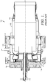
FIG. 2 is a cross section of a gas turbine combustor in accordance with an embodiment of the present invention. -
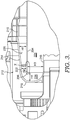
FIG. 3 is a detailed cross section of a portion of the gas turbine combustor ofFIG. 2 in accordance with an embodiment of the present invention. -
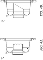
FIG. 4A is a cross section view of a dome assembly in accordance with an embodiment of the present invention. -
FIG. 4B is a cross section view of a dome assembly in accordance with an alternate embodiment of the present invention. -
FIG. 5 is a flow diagram disclosing a process of regulating the fuel-air mixture entering a gas turbine combustor. -
FIG. 6 is a cross section view of a portion of a combustion liner in accordance with the prior art. -
FIG. 7 is a cross section view of a portion of a combustion liner in accordance with an embodiment of the present invention. -
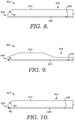
FIG. 8 is a cross section view of a portion of a combustion liner in accordance with an alternate embodiment not according to the present invention. -
FIG. 9 is a cross section view of a portion of a combustion liner in accordance with yet another alternate embodiment of the present invention. -
FIG. 10 is a cross section view of a portion of a combustion liner in accordance with another embodiment not according the present invention. -
FIG. 11 is a flow diagram depicting a process for directing a fuel and air mixture into a combustion liner in accordance with an embodiment of the present invention. - The present invention discloses a system and method for controlling velocity of a fuel-air mixture being injected into a combustion system. That is, a predetermined effective flow area is maintained through two co-axial structures forming an annulus of a known effective flow area through which a fuel-air mixture passes.
- The present invention will now be discussed with respect to
FIGS. 2-8 . An embodiment of a gasturbine combustion system 200 in which the present invention operates is depicted inFIG. 2 . Thecombustion system 200 is an example of a multi-stage combustion system and extends about a longitudinal axis A-A and includes a generallycylindrical flow sleeve 202 for directing a predetermined amount of compressor air along an outer surface of a generally cylindrical andco-axial combustion liner 204. Thecombustion liner 204 has aninlet end 206 and opposingoutlet end 208. Thecombustion system 200 also comprises a set ofmain fuel injectors 210 that are positioned radially outward of thecombustion liner 204 and proximate an upstream end of theflow sleeve 202. The set ofmain fuel injectors 210 direct a controlled amount of fuel into the passing air stream to provide a fuel-air-mixture for thecombustion system 200. - For the embodiment of the present invention shown in
FIG. 2 , themain fuel injectors 210 are located radially outward of thecombustion liner 204 and spread in an annular array about thecombustion liner 204. Themain fuel injectors 210 are divided into two stages with a first stage extending approximately 120 degrees about thecombustion liner 204 and a second stage extending the remaining annular portion, or approximately 240 degrees, about thecombustion liner 204. The first stage of themain fuel injectors 210 are used to generate a Main 1 flame while the second stage of themain fuel injectors 210 generate a Main 2 flame. - The
combustion system 200 also comprises acombustor dome assembly 212, which, as shown inFIGS. 2 and3 , encompasses theinlet end 206 of thecombustion liner 204. More specifically, thedome assembly 212 has an outerannular wall 214 that extends from proximate the set ofmain fuel injectors 210 to a generally hemispherical-shaped cap 216, which is positioned a distance forward of theinlet end 206 of thecombustion liner 204. Thedome assembly 212 turns through the hemispherical-shaped cap 216 and extends a distance into thecombustion liner 204 through a dome assemblyinner wall 218. - As a result of the geometry of the
combustor dome assembly 212 in conjunction with thecombustion liner 204, a series of passageways are formed between parts of thecombustor dome assembly 212 and thecombustion liner 204. Afirst passageway 220 is formed between the outerannular wall 214 and thecombustion liner 204. Referring toFIG. 3 , afirst passageway 220 tapers in size, from a first radial height H1 proximate the set ofmain fuel injectors 210 to a smaller height H2 at asecond passageway 222. Thefirst passageway 220 tapers at an angle to accelerate the flow to a target threshold velocity at a location H2 to provide adequate flashback margin. That is, when velocity of a fuel-air mixture is high enough, should a flashback occur in the combustion system, the velocity of the fuel-air mixture through the second passageway will prevent a flame from being maintained in this region. - The
second passageway 222 is formed between a cylindrical portion of the outerannular wall 214 and thecombustion liner 204, proximate theinlet end 206 of the combustion liner and is in fluid communication with thefirst passageway 220. Thesecond passageway 222 is formed between two cylindrical portions and has a second radial height H2 measured between the outer surface of thecombustion liner 204 and the inner surface of the outerannular wall 214. Thecombustor dome assembly 212 also comprises athird passageway 224 that is also cylindrical and positioned between thecombustion liner 204 and the outerannular wall 214. Thecombustor dome assembly 212 also comprises athird passageway 224 that is also cylindrical and positioned between thecombustion liner 204 andinner wall 218. The third passageway has a third radial height H3, and like the second passageway, is formed by two cylindrical walls -combustion liner 204 and dome assemblyinner wall 218. - As discussed above, the
first passageway 220 tapers into thesecond passageway 222, which is generally cylindrical in nature. The second radial height H2 serves as the limiting region through which the fuel-air mixture must pass. The radial height H2 is regulated and kept consistent from part-to-part by virtue of its geometry, as it is controlled by two cylindrical (i.e. not tapered) surfaces, as shown inFIG. 3 . That is, by utilizing a cylindrical surface as a limiting flow area, better dimensional control is provided because more accurate machining techniques and control of machining tolerances of a cylindrical surface is achievable, compared to that of tapered surfaces. For example, it is well within standard machining capability to hold tolerances of cylindrical surfaces to within +/- 0,00254 cm (0.001 inches). - Utilizing the cylindrical geometry of the
second passageway 222 andthird passageway 224 provides a more effective way to control and regulate the effective flow area and controlling the effective flow area allows for the fuel-air mixture to be maintained at predetermined and known velocities. By being able to regulate the velocity of the mixture, the velocity can be maintained at a rate high enough to ensure flashback of the flame does not occur in thedome assembly 212. - One such way to express these critical passageway geometries shown in
FIGS. 2-4B is through a turning radius ratio of the second passageway height H2 relative to the third passageway height H3. That is, the minimal height relative to the height of the combustion inlet region. For example, in the embodiment of the present invention depicted herein, the ratio of H2/H3 is approximately 0.32. This aspect ratio controls the size of the recirculation and stabilization trapped vortex that resides adjacent to the liner, which effects overall combustor stability. For example, for the embodiment shown inFIGS. 2 and3 , utilizing this geometry permits velocity of the fuel-air mixture in the second passageway to remain within a range of approximately 40-80 meters per second. However, the ratio can vary depending on the desired passageway heights, fuel-air mixture mass flow rate and combustor velocities. For the combustion system disclosed, the ratio of H2/H3 can range from approximately 0.1 to approximately 0.5. More specifically, for an embodiment of the present invention, the first radial height H1 can range from approximately 15 millimeters to approximately 50 millimeters, while the second radial height H2 can range from approximately 10 millimeters to approximately 45 millimeters, and the third radial height H3 can range from approximately 30 millimeters to approximately 100 millimeters. - As discussed above, the combustion system also comprises a
fourth passageway 226 having a fourth height H4, where thefourth passageway 226 is located between theinlet end 206 of the combustion liner and the hemispherical-shapedcap 216. As it can be seen fromFIG. 3 , thefourth passageway 226 is positioned within the hemispherical-shapedcap 216 with the fourth height measured along the distance from theinlet end 206 of the liner to the intersecting location at the hemispherical-shapedcap 216. As such, the fourth height H4 is greater than the second radial height H2, but the fourth height H4 is less than the third radial height H3. This relative height configuration of the second, third and fourth passageways permits the fuel-air mixture to be controlled (at H2), turn through the hemispherical-shaped cap 216 (at H4) and enter the combustion liner 204 (at H3) all in a manner so as to ensure the fuel-air mixture velocity is fast enough that the fuel-air mixture remains attached to the surface of thedome assembly 212, as an unattached, or separated, fuel-air mixture could present a possible condition for supporting a flame in the event of a flashback. - As it can be seen from
FIG. 3 , the height of thefirst passageway 220 tapers as a result, at least in part, of the shape of outerannular wall 214. More specifically, thefirst passageway 220 has its largest height at a region adjacent the set ofmain fuel injectors 210 and its minimum height at the region adjacent the second passageway. Alternate embodiments of thedome cap assembly 212 having the passageway geometry described above are shown in better detail inFIGS. 4A and 4B . - Turning to
FIG. 5 , amethod 500 of controlling a velocity of a fuel-air mixture for a gas turbine combustor is disclosed. Themethod 500 comprises astep 502 of directing a fuel-air mixture through a first passageway that is located radially outward of a combustion liner. Then, in astep 504, the fuel-air mixture is directed from the first passageway and into a second passageway that is also located radially outward of the combustion liner. In astep 506, the fuel-air mixture is directed from the second passageway and into the fourth passageway formed by thehemispherical dome cap 216. As a result, the fuel-air mixture reverses its flow direction to now be directed into the combustion liner. Then, in astep 508, the fuel-air mixture is directed through a third passageway located within the combustion liner such that the fuel-air mixture passes downstream into the combustion liner. - As one skilled in the art understands, a gas turbine engine typically incorporates a plurality of combustors. Generally, for the purpose of discussion, the gas turbine engine may include low emission combustors such as those disclosed herein and may be arranged in a can-annular configuration about the gas turbine engine. One type of gas turbine engine (e.g., heavy duty gas turbine engines) may be typically provided with, but not limited to, six to eighteen individual combustors, each of them fitted with the components outlined above. Accordingly, based on the type of gas turbine engine, there may be several different fuel circuits utilized for operating the gas turbine engine. The
combustion system 200 disclosed inFIGS. 2 and3 is a multi-stage premixing combustion system comprising four stages of fuel injection based on the loading of the engine. However, it is envisioned that the specific fuel circuitry and associated control mechanisms could be modified to include fewer or additional fuel circuits. - Referring now to
FIGS. 6-11 , additional details regarding an aspect of the combustion liner inlet region are depicted and discussed. Turning first toFIG. 6 , a detailed view of the inlet end of a combustion liner of the prior art is shown. More specifically, a combustion liner 600 has a generallyannular body 602 with athickness 604 and athermal barrier coating 606 applied along aninner surface 608 of the generallyannular body 602. The combustion liner 600 has aninlet end 610. In this prior art embodiment, thethermal barrier coating 606 extends to theinlet end 610, and together forms ablunt face 612. That is, for an embodiment of the prior art, theinlet end 610 has a combined thickness (metal + thermal barrier coating) upwards of 0,2286 cm (0.090 inches) or greater, depending on the sheet metal thickness used for the combustion liner 600. When such a combustion liner 600 is used in conjunction with a combustion system ofFIGS. 2-5 , the combustion liner 600 and itsinlet end 610 form a bluff body that can yield undesirable results when the flow of fuel and air pass along and around theinlet end 610. More specifically, as the flow of fuel and air pass around theinlet end 610, the fuel and air mixture tends to separate as it enters the combustion liner 600 due to the bluff body geometry. As one skilled in the art understands, flow separation such as this can help to anchor a flame at or near theinlet end 610. This undesirable result causes theinlet end 610 of the combustion liner 600 to be eroded by the flame formed in this area of recirculation resulting in premature repair or replacement to the combustion liner. - Improvements to the
inlet end 610 of the prior art combustion liner are depicted inFIG. 7 . In an embodiment of the present invention, acombustion liner 700 is provided having a generallyannular body 702 having a thickness T that varies towards aforward region 704. Thecombustion liner 700 also has aninlet end 706 and an opposing outlet end (not shown). The generallyannular body 702 also has aninner surface 708 and an opposing outer surface having a contoured profile proximate theinlet end 706 comprising a firstouter surface 710 and a secondouter surface 712 where the firstouter surface 710 is located radially outward of the secondouter surface 712. - The
forward region 704 of thecombustion liner 700 also has afirst chamfer 714 extending from the firstouter surface 710 towards theinlet end 706, thereby reducing the thickness of thecombustion liner 700 in theforward region 704. For the embodiment depicted inFIG. 7 , thefirst chamfer 714 is oriented at approximately a 5-75 degree angle and reduces the thickness of thecombustion liner 700 from approximately 0,254 - 0,635 cm (0.1-0.25 inches) to approximately 0,0127- 0,254 cm (0.005 - 0.1 inches) at theinlet end 706. The chamfer angle, resulting thickness, and rate of change for the thickness of the combustion liner are merely representative and not meant to be limiting the scope of the present invention. As one skilled in the art will understand, the thickness of the combustion liner, chamfer angle, and rate of thickness change towards theinlet end 706 can vary. However, by tapering the thickness change viafirst chamfer 714 at a first rate, more of the flow of fuel and air passing along the outer surface of the generallyannular body 702 remains attached to theannular body 702 as opposed to prior art designs. - The
combustion liner 700 also comprises acoating 716 applied to theinner surface 708 of the generallyannular body 702. One such coating utilized for thecombustion liner 700 is a thermal barrier coating. Thethermal barrier coating 716 applied to theinner surface 708 comprises abond coating 718 and a ceramictop coating 720. For example, thebond coating 718 can be applied approximately 0,00254 - 0,0254 cm (0.001 - 0.010 inches) thick, while the ceramictop coating 720 can be applied approximately 0,0254-0,508 cm (0.010 - 0.200 inches) thick over thebond coating 718. As one skilled in the art understands, the thermal barrier coating can be a standard commercial coating discussed above or can also be a more advanced thermal barrier coating such as a dense vertically cracked coating. As it can be seen fromFIG. 7 , a portion of the coating proximate theinlet end 706 is tapered via asecond chamfer 722 oriented at an angle of 5-75 degrees, which tapers the coating thickness towards theinlet end 706 at a second rate. Thesecond chamfer 722 can be formed via a machining process, such as grinding to a previously-applied coating, or it can be formed as a result of tapering the layers of bond coating and thermal barrier coating applied. - Therefore, as it can be seen by
FIG. 7 , thefirst chamfer 714 and thesecond chamfer 722 form a reducedbluff body region 724 at theinlet end 706. In an embodiment of the present invention, the reducedbluff body region 724 has a thickness of approximately 0,0508 cm (0.020 inches). However, other reducedbluff body regions 724 can be utilized depending on the desired configuration of thecombustion liner 700. As discussed above, a bluff body region creates a recirculation zone. However, the chamfer angles 714 and 722 of the present invention reduce the size of such a region so as to reduce the tendency for the flow of fuel and air to separate as it passes towards theinlet end 706. - However, with the reduced
bluff body region 724 formed by the present invention, the flow of fuel and air passing along the outer region of the generallyannular body 702 remains along the taperedsurfaces - In an alternate embodiment, the chamfer at the
liner inlet end 706 may instead comprise a rounded bluff body region or a rounded portion of the liner inlet end as shown inFIGS. 8-10 . More specifically, and as shown inFIGS. 8-10 , acombustion liner 800 has aninlet end 806 and instead of the chamfer angles 714 and 722 shown inFIG. 7 , thecombustion liner 800 has one or more radii at theinlet end 806. That is, thecombustion liner 800 comprises a generallyannular body 802 with aninlet end 806 and an outlet end (not shown). Theannular body 802 has aninner surface 808 and anouter surface 810. In this embodiment, theinner surface 808 has athermal barrier coating 820 applied thereto. However, unlike the embodiment ofFIG. 7 , this embodiment includes one or more radii formed into thecombustion liner 800 at the liner inlet. More specifically, inFIG. 8 , which is not part of the present invention, the one or more radii comprise a radius R to the generallyannular body 802 about theouter surface 810proximate inlet end 806. Radius R can vary depending on a variety of factors. However, it is preferred that radius R extends a distance so as to extend generally equivalent to the length of the taperedsurface 714 of the embodiment inFIG. 7 . As such, the radius R covers the same general region of the taperedsurface 714. However, while a radius provides a similar benefit to that of the taperedsurface 714, it is not as advantageous as thetapered surface 714. The radius R increases the risk of separation of the air flow as a result of the curved surface. Also, such a radius negatively affects any flame holding in the area. - Alternatively, and as shown in
FIG. 9 , the one or more radius R to thecombustion liner 800 is formed along thethermal barrier coating 820 applied to theinner surface 808 at theinlet end 806. The radius R of thethermal barrier coating 820 can vary depending on the coating thickness. As with the embodiment ofFIG. 8 , the radius R to the thermal barrier coating also negatively affects flame holding in theinlet end 806. - Then, referring to
FIG. 10 , which is not part of the present invention, the one or more radii R can comprise a first radius R1 and a second radius R2. More specifically, the generallyannular body 802 has a first radius R1 that is generally greater than the radius R2 of thethermal barrier coating 820. As such, the combination of R1 and R2 at theinlet end 806 forms a shape comparable to a bullnose at the inlet to the combustion liner. - The configurations disclosed in
FIGS. 8-10 provide a blunt front edge of the combustion liner that is necessary for the liner structural integrity. However, reducing the front edge thickness prevents premature thermal wear of the combustionliner inlet end 806 by reducing the tendency for flame holding. The radii R, R1 and/or R2 are formed preferably by a grinding process to the liner and/or thermal barrier coating. - Referring now to
FIG. 11 , amethod 1100 of reducing a recirculation zone in a gas turbine combustor is disclosed. More specifically, in astep 1102, a combustion liner is provided having a chamfer along an outer surface of the combustion liner, a coating applied to an inner surface of the combustion liner, and a chamfer to the coating on the inner surface. Then, in astep 1104, a fuel and air mixture is directed along the outer surface of the combustion liner. The fuel and air mixture is then turned about an inlet end of the combustion liner in astep 1106, such that the mixture remains at least in close proximity to the chamfered portions of the combustion liner. Then, in astep 1108, the fuel and air mixture is directed into the combustion liner where it is ignited to supply power to the gas turbine engine. - While the invention has been described in what is known as presently the preferred embodiment, it is to be understood that the invention is not to be limited to the disclosed embodiment but, on the contrary, is intended to cover various modifications and equivalent arrangements within the scope of the following claims. The present invention has been described in relation to particular embodiments, which are intended in all respects to be illustrative rather than restrictive.
Claims (8)
- A combustion liner (700) comprising: a generally annular body (702) having thickness, an inlet end (706), and an opposing outlet end, the generally annular body (702) having an inner surface (708) and an opposing outer surface. the outer surface having a contoured profile proximate the inlet end (706) such that the outer surface comprises a first outer surface (710) and a second outer surface (712) with the first outer surface (710) located radially outward of the second outer surface (712) and a first chamfer (714) extending from the first outer surface (710) to the inlet end (706); and, a coating (716) applied to the inner surface (708), where the coating comprises a bond coating (718) and a ceramic top coating (720), the combustion liner (700) being characterised in at least a portion of the coating proximate the inlet end (706) having a second chamfer (722) thereby tapering a coating thickness towards the inlet end (706).
- The combustion liner of claim 1, wherein the first chamfer (714) and second chamfer (722) form a reduced bluff body region (724) at the inlet end (706); wherein the bluff body region (724) at the inlet end (706) provides for a recirculation zone proximate the inlet end (706) of the combustion liner (700).
- The combustion liner of claim 1, wherein the coating applied to the inner surface (708) of the combustion liner (700) has a dense vertically cracked microstructure.
- A method of reducing a recirculation zone in a combustion liner (700) comprising: providing a combustion liner (700) having a first chamfer (714) along an outer surface of the combustion liner (700), a coating (716) applied to an inner surface (708) of the combustion liner (700), and a second chamfer (722) to at least a portion of the coating (716) on the inner surface (708), directing a fuel and air mixture along the outer surface of the combustion liner (700); turning the fuel and air mixture about an inlet end (706) of the combustion liner (700) such that the mixture remains at least in close proximity to the first chamfer (714) and to the second chamfer (722) of the combustion liner (700); and, directing the mixture into the combustion liner (700).
- The method of claim 4, wherein the inlet end (706) forms a bluff body (724) having a reduced thickness compared to that of the combustion liner (700) and the coating (716).
- The method of claim 5, wherein the bluff body 724 has a thickness of approximately 0,0127 - 0,127 cm (0.005 - 0.050 inches).
- A combustion liner (800) comprising: a generally annular body (802) having thickness, an inlet end (806), and an opposing outlet end, the generally annular body (802) having an inner surface (808) and an opposing outer surface (810), the outer surface (810) having a contoured profile proximate the inlet end (806) such that the outer surface (810) comprises a first outer surface and a second outer surface with the first outer surface located radially outward of the second outer surface and a first chamfer extending from the first outer surface to the inlet end (806); and, a coating (820) applied to the inner surface (808), where the coating (820) comprises a bond coating and a ceramic top coating, the combustion liner (800) being characterised in at least a portion of the coating proximate the inlet end (806) having a radius at the inlet end (806).
- A combustion liner (800) comprising: a generally annular body (802) having a thickness, an inlet end (806), and an opposing outlet end, the generally annular body (802) having an inner surface (808) and an opposing outer surface (810); and a coating (820) applied to the inner surface (808), where the coating (820) comprises a bond coating and a ceramic top coating; the combustion liner (800) being characterised in the outer surface (810) being contoured proximate the inlet end (806) according to a radius, and at least a portion of the coating (820) proximate the inlet end (806) having a chamfer thereby tapering a coating thickness towards the inlet end (806).
Applications Claiming Priority (2)
| Application Number | Priority Date | Filing Date | Title |
|---|---|---|---|
| US14/549,922 US10060630B2 (en) | 2012-10-01 | 2014-11-21 | Flamesheet combustor contoured liner |
| PCT/US2015/061926 WO2016099805A2 (en) | 2014-11-21 | 2015-11-20 | Flamesheet combustor contoured liner |
Publications (3)
| Publication Number | Publication Date |
|---|---|
| EP3221643A2 EP3221643A2 (en) | 2017-09-27 |
| EP3221643A4 EP3221643A4 (en) | 2018-09-05 |
| EP3221643B1 true EP3221643B1 (en) | 2020-02-26 |
Family
ID=56127814
Family Applications (1)
| Application Number | Title | Priority Date | Filing Date |
|---|---|---|---|
| EP15870609.3A Active EP3221643B1 (en) | 2014-11-21 | 2015-11-20 | Combustion liner and method of reducing a recirculation zone of a combustion liner |
Country Status (5)
| Country | Link |
|---|---|
| EP (1) | EP3221643B1 (en) |
| JP (1) | JP6824165B2 (en) |
| KR (1) | KR102405991B1 (en) |
| CN (1) | CN107429920B (en) |
| WO (1) | WO2016099805A2 (en) |
Cited By (1)
| Publication number | Priority date | Publication date | Assignee | Title |
|---|---|---|---|---|
| US11859819B2 (en) | 2021-10-15 | 2024-01-02 | General Electric Company | Ceramic composite combustor dome and liners |
Families Citing this family (2)
| Publication number | Priority date | Publication date | Assignee | Title |
|---|---|---|---|---|
| US10684014B2 (en) * | 2016-08-04 | 2020-06-16 | Raytheon Technologies Corporation | Combustor panel for gas turbine engine |
| US10823410B2 (en) * | 2016-10-26 | 2020-11-03 | Raytheon Technologies Corporation | Cast combustor liner panel radius for gas turbine engine combustor |
Family Cites Families (25)
| Publication number | Priority date | Publication date | Assignee | Title |
|---|---|---|---|---|
| CA1231240A (en) * | 1983-08-26 | 1988-01-12 | Westinghouse Electric Corporation | Varying thickness thermal barrier for combustion turbine baskets |
| US5619855A (en) * | 1995-06-07 | 1997-04-15 | General Electric Company | High inlet mach combustor for gas turbine engine |
| US6047539A (en) * | 1998-04-30 | 2000-04-11 | General Electric Company | Method of protecting gas turbine combustor components against water erosion and hot corrosion |
| JP3364169B2 (en) * | 1999-06-09 | 2003-01-08 | 三菱重工業株式会社 | Gas turbine and its combustor |
| US6408610B1 (en) * | 2000-07-18 | 2002-06-25 | General Electric Company | Method of adjusting gas turbine component cooling air flow |
| US6573474B1 (en) * | 2000-10-18 | 2003-06-03 | Chromalloy Gas Turbine Corporation | Process for drilling holes through a thermal barrier coating |
| US20030203224A1 (en) * | 2001-07-30 | 2003-10-30 | Diconza Paul Josesh | Thermal barrier coating of intermediate density |
| US20030202269A1 (en) * | 2002-04-29 | 2003-10-30 | Jack Chen | Method for storing or rescuing data or information |
| JP2004092392A (en) * | 2002-07-12 | 2004-03-25 | Toshiba Corp | Thermal barrier coating application method |
| US7216485B2 (en) * | 2004-09-03 | 2007-05-15 | General Electric Company | Adjusting airflow in turbine component by depositing overlay metallic coating |
| US7237384B2 (en) * | 2005-01-26 | 2007-07-03 | Peter Stuttaford | Counter swirl shear mixer |
| US7581402B2 (en) * | 2005-02-08 | 2009-09-01 | Siemens Energy, Inc. | Turbine engine combustor with bolted swirlers |
| US20070202269A1 (en) * | 2006-02-24 | 2007-08-30 | Potter Kenneth B | Local repair process of thermal barrier coatings in turbine engine components |
| US7540152B2 (en) * | 2006-02-27 | 2009-06-02 | Mitsubishi Heavy Industries, Ltd. | Combustor |
| US7770395B2 (en) * | 2006-02-27 | 2010-08-10 | Mitsubishi Heavy Industries, Ltd. | Combustor |
| US8146364B2 (en) * | 2007-09-14 | 2012-04-03 | Siemens Energy, Inc. | Non-rectangular resonator devices providing enhanced liner cooling for combustion chamber |
| US8586172B2 (en) * | 2008-05-06 | 2013-11-19 | General Electric Company | Protective coating with high adhesion and articles made therewith |
| US8397511B2 (en) * | 2009-05-19 | 2013-03-19 | General Electric Company | System and method for cooling a wall of a gas turbine combustor |
| WO2011018853A1 (en) * | 2009-08-13 | 2011-02-17 | 三菱重工業株式会社 | Combustor |
| US20110048017A1 (en) * | 2009-08-27 | 2011-03-03 | General Electric Company | Method of depositing protective coatings on turbine combustion components |
| JP5320352B2 (en) * | 2010-07-15 | 2013-10-23 | 三菱重工業株式会社 | Thermal barrier coating member and manufacturing method thereof, thermal barrier coating material, gas turbine, and sintered body |
| US9347669B2 (en) * | 2012-10-01 | 2016-05-24 | Alstom Technology Ltd. | Variable length combustor dome extension for improved operability |
| US10088162B2 (en) * | 2012-10-01 | 2018-10-02 | United Technologies Corporation | Combustor with grommet having projecting lip |
| US9897317B2 (en) * | 2012-10-01 | 2018-02-20 | Ansaldo Energia Ip Uk Limited | Thermally free liner retention mechanism |
| US9765973B2 (en) * | 2013-03-12 | 2017-09-19 | General Electric Company | System and method for tube level air flow conditioning |
-
2015
- 2015-11-20 KR KR1020177016151A patent/KR102405991B1/en not_active Expired - Fee Related
- 2015-11-20 JP JP2017527325A patent/JP6824165B2/en active Active
- 2015-11-20 CN CN201580074243.2A patent/CN107429920B/en active Active
- 2015-11-20 EP EP15870609.3A patent/EP3221643B1/en active Active
- 2015-11-20 WO PCT/US2015/061926 patent/WO2016099805A2/en not_active Ceased
Non-Patent Citations (1)
| Title |
|---|
| None * |
Cited By (1)
| Publication number | Priority date | Publication date | Assignee | Title |
|---|---|---|---|---|
| US11859819B2 (en) | 2021-10-15 | 2024-01-02 | General Electric Company | Ceramic composite combustor dome and liners |
Also Published As
| Publication number | Publication date |
|---|---|
| EP3221643A2 (en) | 2017-09-27 |
| WO2016099805A3 (en) | 2016-10-27 |
| CN107429920A (en) | 2017-12-01 |
| EP3221643A4 (en) | 2018-09-05 |
| CN107429920B (en) | 2019-11-05 |
| JP2017536524A (en) | 2017-12-07 |
| WO2016099805A2 (en) | 2016-06-23 |
| JP6824165B2 (en) | 2021-02-03 |
| KR102405991B1 (en) | 2022-06-10 |
| KR20170106302A (en) | 2017-09-20 |
Similar Documents
| Publication | Publication Date | Title |
|---|---|---|
| EP2904326B1 (en) | Flamesheet combustor dome | |
| US10060630B2 (en) | Flamesheet combustor contoured liner | |
| US8001761B2 (en) | Method and apparatus for actively controlling fuel flow to a mixer assembly of a gas turbine engine combustor | |
| EP1413830B1 (en) | Piloted airblast fuel injector with modified air splitter | |
| EP2971970B1 (en) | Counter swirl doublet combustor | |
| GB2451144A (en) | Method and apparatus for actively controlling fuel flow to a mixer assembly of a gas turbine engine combustor | |
| US9810432B2 (en) | Method for premixing air with a gaseous fuel and burner arrangement for conducting said method | |
| EP3472518B1 (en) | Fuel oil axial stage combustion for improved turbine combustor performance | |
| EP3169938B1 (en) | Axially staged gas turbine combustor with interstage premixer | |
| KR102405991B1 (en) | Flamesheet combustor contoured liner | |
| CA2595061C (en) | Method and apparatus for actively controlling fuel flow to a mixer assembly of a gas turbine engine combustor | |
| US20170051919A1 (en) | Swirler for a burner of a gas turbine engine, burner of a gas turbine engine and gas turbine engine | |
| US20150020501A1 (en) | An annular combustion chamber in a turbine engine | |
| Chin et al. | Design Considerations for Extra High-Pressure Ratio (70) Civil Aero Engine Low-Emission Combustor |
Legal Events
| Date | Code | Title | Description |
|---|---|---|---|
| STAA | Information on the status of an ep patent application or granted ep patent |
Free format text: STATUS: THE INTERNATIONAL PUBLICATION HAS BEEN MADE |
|
| PUAI | Public reference made under article 153(3) epc to a published international application that has entered the european phase |
Free format text: ORIGINAL CODE: 0009012 |
|
| STAA | Information on the status of an ep patent application or granted ep patent |
Free format text: STATUS: REQUEST FOR EXAMINATION WAS MADE |
|
| 17P | Request for examination filed |
Effective date: 20170609 |
|
| AK | Designated contracting states |
Kind code of ref document: A2 Designated state(s): AL AT BE BG CH CY CZ DE DK EE ES FI FR GB GR HR HU IE IS IT LI LT LU LV MC MK MT NL NO PL PT RO RS SE SI SK SM TR |
|
| AX | Request for extension of the european patent |
Extension state: BA ME |
|
| DAV | Request for validation of the european patent (deleted) | ||
| DAX | Request for extension of the european patent (deleted) | ||
| REG | Reference to a national code |
Ref country code: DE Ref legal event code: R079 Ref document number: 602015047929 Country of ref document: DE Free format text: PREVIOUS MAIN CLASS: F23R0003420000 Ipc: F23R0003000000 |
|
| A4 | Supplementary search report drawn up and despatched |
Effective date: 20180807 |
|
| RIC1 | Information provided on ipc code assigned before grant |
Ipc: F23R 3/28 20060101ALI20180801BHEP Ipc: F23R 3/00 20060101AFI20180801BHEP Ipc: F23R 3/46 20060101ALI20180801BHEP |
|
| GRAP | Despatch of communication of intention to grant a patent |
Free format text: ORIGINAL CODE: EPIDOSNIGR1 |
|
| STAA | Information on the status of an ep patent application or granted ep patent |
Free format text: STATUS: GRANT OF PATENT IS INTENDED |
|
| INTG | Intention to grant announced |
Effective date: 20190821 |
|
| GRAJ | Information related to disapproval of communication of intention to grant by the applicant or resumption of examination proceedings by the epo deleted |
Free format text: ORIGINAL CODE: EPIDOSDIGR1 |
|
| GRAL | Information related to payment of fee for publishing/printing deleted |
Free format text: ORIGINAL CODE: EPIDOSDIGR3 |
|
| GRAS | Grant fee paid |
Free format text: ORIGINAL CODE: EPIDOSNIGR3 |
|
| STAA | Information on the status of an ep patent application or granted ep patent |
Free format text: STATUS: REQUEST FOR EXAMINATION WAS MADE |
|
| GRAR | Information related to intention to grant a patent recorded |
Free format text: ORIGINAL CODE: EPIDOSNIGR71 |
|
| STAA | Information on the status of an ep patent application or granted ep patent |
Free format text: STATUS: GRANT OF PATENT IS INTENDED |
|
| GRAA | (expected) grant |
Free format text: ORIGINAL CODE: 0009210 |
|
| STAA | Information on the status of an ep patent application or granted ep patent |
Free format text: STATUS: THE PATENT HAS BEEN GRANTED |
|
| INTC | Intention to grant announced (deleted) | ||
| AK | Designated contracting states |
Kind code of ref document: B1 Designated state(s): AL AT BE BG CH CY CZ DE DK EE ES FI FR GB GR HR HU IE IS IT LI LT LU LV MC MK MT NL NO PL PT RO RS SE SI SK SM TR |
|
| INTG | Intention to grant announced |
Effective date: 20200121 |
|
| REG | Reference to a national code |
Ref country code: GB Ref legal event code: FG4D |
|
| REG | Reference to a national code |
Ref country code: CH Ref legal event code: EP |
|
| REG | Reference to a national code |
Ref country code: AT Ref legal event code: REF Ref document number: 1238084 Country of ref document: AT Kind code of ref document: T Effective date: 20200315 |
|
| REG | Reference to a national code |
Ref country code: IE Ref legal event code: FG4D |
|
| REG | Reference to a national code |
Ref country code: DE Ref legal event code: R096 Ref document number: 602015047929 Country of ref document: DE |
|
| REG | Reference to a national code |
Ref country code: NL Ref legal event code: FP |
|
| PG25 | Lapsed in a contracting state [announced via postgrant information from national office to epo] |
Ref country code: RS Free format text: LAPSE BECAUSE OF FAILURE TO SUBMIT A TRANSLATION OF THE DESCRIPTION OR TO PAY THE FEE WITHIN THE PRESCRIBED TIME-LIMIT Effective date: 20200226 Ref country code: FI Free format text: LAPSE BECAUSE OF FAILURE TO SUBMIT A TRANSLATION OF THE DESCRIPTION OR TO PAY THE FEE WITHIN THE PRESCRIBED TIME-LIMIT Effective date: 20200226 Ref country code: NO Free format text: LAPSE BECAUSE OF FAILURE TO SUBMIT A TRANSLATION OF THE DESCRIPTION OR TO PAY THE FEE WITHIN THE PRESCRIBED TIME-LIMIT Effective date: 20200526 |
|
| REG | Reference to a national code |
Ref country code: LT Ref legal event code: MG4D |
|
| PG25 | Lapsed in a contracting state [announced via postgrant information from national office to epo] |
Ref country code: IS Free format text: LAPSE BECAUSE OF FAILURE TO SUBMIT A TRANSLATION OF THE DESCRIPTION OR TO PAY THE FEE WITHIN THE PRESCRIBED TIME-LIMIT Effective date: 20200626 Ref country code: BG Free format text: LAPSE BECAUSE OF FAILURE TO SUBMIT A TRANSLATION OF THE DESCRIPTION OR TO PAY THE FEE WITHIN THE PRESCRIBED TIME-LIMIT Effective date: 20200526 Ref country code: SE Free format text: LAPSE BECAUSE OF FAILURE TO SUBMIT A TRANSLATION OF THE DESCRIPTION OR TO PAY THE FEE WITHIN THE PRESCRIBED TIME-LIMIT Effective date: 20200226 Ref country code: LV Free format text: LAPSE BECAUSE OF FAILURE TO SUBMIT A TRANSLATION OF THE DESCRIPTION OR TO PAY THE FEE WITHIN THE PRESCRIBED TIME-LIMIT Effective date: 20200226 Ref country code: HR Free format text: LAPSE BECAUSE OF FAILURE TO SUBMIT A TRANSLATION OF THE DESCRIPTION OR TO PAY THE FEE WITHIN THE PRESCRIBED TIME-LIMIT Effective date: 20200226 Ref country code: GR Free format text: LAPSE BECAUSE OF FAILURE TO SUBMIT A TRANSLATION OF THE DESCRIPTION OR TO PAY THE FEE WITHIN THE PRESCRIBED TIME-LIMIT Effective date: 20200527 |
|
| PG25 | Lapsed in a contracting state [announced via postgrant information from national office to epo] |
Ref country code: DK Free format text: LAPSE BECAUSE OF FAILURE TO SUBMIT A TRANSLATION OF THE DESCRIPTION OR TO PAY THE FEE WITHIN THE PRESCRIBED TIME-LIMIT Effective date: 20200226 Ref country code: PT Free format text: LAPSE BECAUSE OF FAILURE TO SUBMIT A TRANSLATION OF THE DESCRIPTION OR TO PAY THE FEE WITHIN THE PRESCRIBED TIME-LIMIT Effective date: 20200719 Ref country code: ES Free format text: LAPSE BECAUSE OF FAILURE TO SUBMIT A TRANSLATION OF THE DESCRIPTION OR TO PAY THE FEE WITHIN THE PRESCRIBED TIME-LIMIT Effective date: 20200226 Ref country code: EE Free format text: LAPSE BECAUSE OF FAILURE TO SUBMIT A TRANSLATION OF THE DESCRIPTION OR TO PAY THE FEE WITHIN THE PRESCRIBED TIME-LIMIT Effective date: 20200226 Ref country code: SM Free format text: LAPSE BECAUSE OF FAILURE TO SUBMIT A TRANSLATION OF THE DESCRIPTION OR TO PAY THE FEE WITHIN THE PRESCRIBED TIME-LIMIT Effective date: 20200226 Ref country code: RO Free format text: LAPSE BECAUSE OF FAILURE TO SUBMIT A TRANSLATION OF THE DESCRIPTION OR TO PAY THE FEE WITHIN THE PRESCRIBED TIME-LIMIT Effective date: 20200226 Ref country code: SK Free format text: LAPSE BECAUSE OF FAILURE TO SUBMIT A TRANSLATION OF THE DESCRIPTION OR TO PAY THE FEE WITHIN THE PRESCRIBED TIME-LIMIT Effective date: 20200226 Ref country code: CZ Free format text: LAPSE BECAUSE OF FAILURE TO SUBMIT A TRANSLATION OF THE DESCRIPTION OR TO PAY THE FEE WITHIN THE PRESCRIBED TIME-LIMIT Effective date: 20200226 Ref country code: LT Free format text: LAPSE BECAUSE OF FAILURE TO SUBMIT A TRANSLATION OF THE DESCRIPTION OR TO PAY THE FEE WITHIN THE PRESCRIBED TIME-LIMIT Effective date: 20200226 |
|
| REG | Reference to a national code |
Ref country code: AT Ref legal event code: MK05 Ref document number: 1238084 Country of ref document: AT Kind code of ref document: T Effective date: 20200226 |
|
| REG | Reference to a national code |
Ref country code: DE Ref legal event code: R097 Ref document number: 602015047929 Country of ref document: DE |
|
| PLBE | No opposition filed within time limit |
Free format text: ORIGINAL CODE: 0009261 |
|
| STAA | Information on the status of an ep patent application or granted ep patent |
Free format text: STATUS: NO OPPOSITION FILED WITHIN TIME LIMIT |
|
| PG25 | Lapsed in a contracting state [announced via postgrant information from national office to epo] |
Ref country code: IT Free format text: LAPSE BECAUSE OF FAILURE TO SUBMIT A TRANSLATION OF THE DESCRIPTION OR TO PAY THE FEE WITHIN THE PRESCRIBED TIME-LIMIT Effective date: 20200226 Ref country code: AT Free format text: LAPSE BECAUSE OF FAILURE TO SUBMIT A TRANSLATION OF THE DESCRIPTION OR TO PAY THE FEE WITHIN THE PRESCRIBED TIME-LIMIT Effective date: 20200226 |
|
| 26N | No opposition filed |
Effective date: 20201127 |
|
| PG25 | Lapsed in a contracting state [announced via postgrant information from national office to epo] |
Ref country code: PL Free format text: LAPSE BECAUSE OF FAILURE TO SUBMIT A TRANSLATION OF THE DESCRIPTION OR TO PAY THE FEE WITHIN THE PRESCRIBED TIME-LIMIT Effective date: 20200226 Ref country code: SI Free format text: LAPSE BECAUSE OF FAILURE TO SUBMIT A TRANSLATION OF THE DESCRIPTION OR TO PAY THE FEE WITHIN THE PRESCRIBED TIME-LIMIT Effective date: 20200226 |
|
| REG | Reference to a national code |
Ref country code: DE Ref legal event code: R082 Ref document number: 602015047929 Country of ref document: DE Representative=s name: DREISS PATENTANWAELTE PARTG MBB, DE Ref country code: DE Ref legal event code: R081 Ref document number: 602015047929 Country of ref document: DE Owner name: H2 IP UK LIMITED, GB Free format text: FORMER OWNER: ANSALDO ENERGIA IP UK LIMITED, LONDON, GB |
|
| PG25 | Lapsed in a contracting state [announced via postgrant information from national office to epo] |
Ref country code: MC Free format text: LAPSE BECAUSE OF FAILURE TO SUBMIT A TRANSLATION OF THE DESCRIPTION OR TO PAY THE FEE WITHIN THE PRESCRIBED TIME-LIMIT Effective date: 20200226 |
|
| REG | Reference to a national code |
Ref country code: CH Ref legal event code: PL |
|
| REG | Reference to a national code |
Ref country code: NL Ref legal event code: PD Owner name: H2 IP UK LIMITED; GB Free format text: DETAILS ASSIGNMENT: CHANGE OF OWNER(S), ASSIGNMENT Effective date: 20210621 |
|
| GBPC | Gb: european patent ceased through non-payment of renewal fee |
Effective date: 20201120 |
|
| PG25 | Lapsed in a contracting state [announced via postgrant information from national office to epo] |
Ref country code: LU Free format text: LAPSE BECAUSE OF NON-PAYMENT OF DUE FEES Effective date: 20201120 |
|
| REG | Reference to a national code |
Ref country code: BE Ref legal event code: MM Effective date: 20201130 |
|
| PG25 | Lapsed in a contracting state [announced via postgrant information from national office to epo] |
Ref country code: LI Free format text: LAPSE BECAUSE OF NON-PAYMENT OF DUE FEES Effective date: 20201130 Ref country code: CH Free format text: LAPSE BECAUSE OF NON-PAYMENT OF DUE FEES Effective date: 20201130 |
|
| PG25 | Lapsed in a contracting state [announced via postgrant information from national office to epo] |
Ref country code: FR Free format text: LAPSE BECAUSE OF NON-PAYMENT OF DUE FEES Effective date: 20201130 Ref country code: IE Free format text: LAPSE BECAUSE OF NON-PAYMENT OF DUE FEES Effective date: 20201120 |
|
| PG25 | Lapsed in a contracting state [announced via postgrant information from national office to epo] |
Ref country code: GB Free format text: LAPSE BECAUSE OF NON-PAYMENT OF DUE FEES Effective date: 20201120 |
|
| PG25 | Lapsed in a contracting state [announced via postgrant information from national office to epo] |
Ref country code: TR Free format text: LAPSE BECAUSE OF FAILURE TO SUBMIT A TRANSLATION OF THE DESCRIPTION OR TO PAY THE FEE WITHIN THE PRESCRIBED TIME-LIMIT Effective date: 20200226 Ref country code: MT Free format text: LAPSE BECAUSE OF FAILURE TO SUBMIT A TRANSLATION OF THE DESCRIPTION OR TO PAY THE FEE WITHIN THE PRESCRIBED TIME-LIMIT Effective date: 20200226 Ref country code: CY Free format text: LAPSE BECAUSE OF FAILURE TO SUBMIT A TRANSLATION OF THE DESCRIPTION OR TO PAY THE FEE WITHIN THE PRESCRIBED TIME-LIMIT Effective date: 20200226 |
|
| PG25 | Lapsed in a contracting state [announced via postgrant information from national office to epo] |
Ref country code: MK Free format text: LAPSE BECAUSE OF FAILURE TO SUBMIT A TRANSLATION OF THE DESCRIPTION OR TO PAY THE FEE WITHIN THE PRESCRIBED TIME-LIMIT Effective date: 20200226 Ref country code: AL Free format text: LAPSE BECAUSE OF FAILURE TO SUBMIT A TRANSLATION OF THE DESCRIPTION OR TO PAY THE FEE WITHIN THE PRESCRIBED TIME-LIMIT Effective date: 20200226 |
|
| PG25 | Lapsed in a contracting state [announced via postgrant information from national office to epo] |
Ref country code: BE Free format text: LAPSE BECAUSE OF NON-PAYMENT OF DUE FEES Effective date: 20201130 |
|
| PG25 | Lapsed in a contracting state [announced via postgrant information from national office to epo] |
Ref country code: IS Free format text: LAPSE BECAUSE OF NON-PAYMENT OF DUE FEES Effective date: 20200626 |
|
| PGFP | Annual fee paid to national office [announced via postgrant information from national office to epo] |
Ref country code: NL Payment date: 20251003 Year of fee payment: 11 |
|
| PGFP | Annual fee paid to national office [announced via postgrant information from national office to epo] |
Ref country code: DE Payment date: 20250923 Year of fee payment: 11 |