EP3221535B1 - Elektromechanischer schlosssatz - Google Patents
Elektromechanischer schlosssatz Download PDFInfo
- Publication number
- EP3221535B1 EP3221535B1 EP15861631.8A EP15861631A EP3221535B1 EP 3221535 B1 EP3221535 B1 EP 3221535B1 EP 15861631 A EP15861631 A EP 15861631A EP 3221535 B1 EP3221535 B1 EP 3221535B1
- Authority
- EP
- European Patent Office
- Prior art keywords
- exterior
- interior
- assembly
- escutcheon
- spindle
- Prior art date
- Legal status (The legal status is an assumption and is not a legal conclusion. Google has not performed a legal analysis and makes no representation as to the accuracy of the status listed.)
- Active
Links
Images


Classifications
-
- E—FIXED CONSTRUCTIONS
- E05—LOCKS; KEYS; WINDOW OR DOOR FITTINGS; SAFES
- E05B—LOCKS; ACCESSORIES THEREFOR; HANDCUFFS
- E05B63/00—Locks or fastenings with special structural characteristics
- E05B63/08—Mortise locks
- E05B63/10—Mortise locks requiring only two cylindrical holes in the wing
-
- E—FIXED CONSTRUCTIONS
- E05—LOCKS; KEYS; WINDOW OR DOOR FITTINGS; SAFES
- E05B—LOCKS; ACCESSORIES THEREFOR; HANDCUFFS
- E05B47/00—Operating or controlling locks or other fastening devices by electric or magnetic means
- E05B47/06—Controlling mechanically-operated bolts by electro-magnetically-operated detents
- E05B47/0676—Controlling mechanically-operated bolts by electro-magnetically-operated detents by disconnecting the handle
- E05B47/068—Controlling mechanically-operated bolts by electro-magnetically-operated detents by disconnecting the handle axially, i.e. with an axially disengaging coupling element
-
- E—FIXED CONSTRUCTIONS
- E05—LOCKS; KEYS; WINDOW OR DOOR FITTINGS; SAFES
- E05B—LOCKS; ACCESSORIES THEREFOR; HANDCUFFS
- E05B47/00—Operating or controlling locks or other fastening devices by electric or magnetic means
- E05B47/0001—Operating or controlling locks or other fastening devices by electric or magnetic means with electric actuators; Constructional features thereof
-
- E—FIXED CONSTRUCTIONS
- E05—LOCKS; KEYS; WINDOW OR DOOR FITTINGS; SAFES
- E05B—LOCKS; ACCESSORIES THEREFOR; HANDCUFFS
- E05B55/00—Locks in which a sliding latch is used also as a locking bolt
- E05B55/005—Cylindrical or tubular locks
-
- G—PHYSICS
- G07—CHECKING-DEVICES
- G07C—TIME OR ATTENDANCE REGISTERS; REGISTERING OR INDICATING THE WORKING OF MACHINES; GENERATING RANDOM NUMBERS; VOTING OR LOTTERY APPARATUS; ARRANGEMENTS, SYSTEMS OR APPARATUS FOR CHECKING NOT PROVIDED FOR ELSEWHERE
- G07C9/00—Individual registration on entry or exit
- G07C9/00174—Electronically operated locks; Circuits therefor; Nonmechanical keys therefor, e.g. passive or active electrical keys or other data carriers without mechanical keys
- G07C9/00944—Details of construction or manufacture
-
- E—FIXED CONSTRUCTIONS
- E05—LOCKS; KEYS; WINDOW OR DOOR FITTINGS; SAFES
- E05B—LOCKS; ACCESSORIES THEREFOR; HANDCUFFS
- E05B47/00—Operating or controlling locks or other fastening devices by electric or magnetic means
- E05B2047/0048—Circuits, feeding, monitoring
-
- E—FIXED CONSTRUCTIONS
- E05—LOCKS; KEYS; WINDOW OR DOOR FITTINGS; SAFES
- E05B—LOCKS; ACCESSORIES THEREFOR; HANDCUFFS
- E05B47/00—Operating or controlling locks or other fastening devices by electric or magnetic means
- E05B2047/0048—Circuits, feeding, monitoring
- E05B2047/0057—Feeding
- E05B2047/0058—Feeding by batteries
-
- E—FIXED CONSTRUCTIONS
- E05—LOCKS; KEYS; WINDOW OR DOOR FITTINGS; SAFES
- E05B—LOCKS; ACCESSORIES THEREFOR; HANDCUFFS
- E05B47/00—Operating or controlling locks or other fastening devices by electric or magnetic means
- E05B2047/0048—Circuits, feeding, monitoring
- E05B2047/0071—Connecting lockparts by electronic communication means only, e.g. bus systems, time multiplexing
-
- E—FIXED CONSTRUCTIONS
- E05—LOCKS; KEYS; WINDOW OR DOOR FITTINGS; SAFES
- E05B—LOCKS; ACCESSORIES THEREFOR; HANDCUFFS
- E05B47/00—Operating or controlling locks or other fastening devices by electric or magnetic means
- E05B2047/0094—Mechanical aspects of remotely controlled locks
-
- E—FIXED CONSTRUCTIONS
- E05—LOCKS; KEYS; WINDOW OR DOOR FITTINGS; SAFES
- E05B—LOCKS; ACCESSORIES THEREFOR; HANDCUFFS
- E05B41/00—Locks with visible indication as to whether the lock is locked or unlocked
-
- G—PHYSICS
- G07—CHECKING-DEVICES
- G07C—TIME OR ATTENDANCE REGISTERS; REGISTERING OR INDICATING THE WORKING OF MACHINES; GENERATING RANDOM NUMBERS; VOTING OR LOTTERY APPARATUS; ARRANGEMENTS, SYSTEMS OR APPARATUS FOR CHECKING NOT PROVIDED FOR ELSEWHERE
- G07C9/00—Individual registration on entry or exit
- G07C9/00174—Electronically operated locks; Circuits therefor; Nonmechanical keys therefor, e.g. passive or active electrical keys or other data carriers without mechanical keys
- G07C9/00309—Electronically operated locks; Circuits therefor; Nonmechanical keys therefor, e.g. passive or active electrical keys or other data carriers without mechanical keys operated with bidirectional data transmission between data carrier and locks
- G07C2009/00365—Electronically operated locks; Circuits therefor; Nonmechanical keys therefor, e.g. passive or active electrical keys or other data carriers without mechanical keys operated with bidirectional data transmission between data carrier and locks in combination with a wake-up circuit
- G07C2009/00373—Electronically operated locks; Circuits therefor; Nonmechanical keys therefor, e.g. passive or active electrical keys or other data carriers without mechanical keys operated with bidirectional data transmission between data carrier and locks in combination with a wake-up circuit whereby the wake-up circuit is situated in the lock
-
- G—PHYSICS
- G07—CHECKING-DEVICES
- G07C—TIME OR ATTENDANCE REGISTERS; REGISTERING OR INDICATING THE WORKING OF MACHINES; GENERATING RANDOM NUMBERS; VOTING OR LOTTERY APPARATUS; ARRANGEMENTS, SYSTEMS OR APPARATUS FOR CHECKING NOT PROVIDED FOR ELSEWHERE
- G07C2209/00—Indexing scheme relating to groups G07C9/00 - G07C9/38
- G07C2209/08—With time considerations, e.g. temporary activation, valid time window or time limitations
-
- Y—GENERAL TAGGING OF NEW TECHNOLOGICAL DEVELOPMENTS; GENERAL TAGGING OF CROSS-SECTIONAL TECHNOLOGIES SPANNING OVER SEVERAL SECTIONS OF THE IPC; TECHNICAL SUBJECTS COVERED BY FORMER USPC CROSS-REFERENCE ART COLLECTIONS [XRACs] AND DIGESTS
- Y10—TECHNICAL SUBJECTS COVERED BY FORMER USPC
- Y10T—TECHNICAL SUBJECTS COVERED BY FORMER US CLASSIFICATION
- Y10T70/00—Locks
- Y10T70/70—Operating mechanism
- Y10T70/7051—Using a powered device [e.g., motor]
- Y10T70/7062—Electrical type [e.g., solenoid]
- Y10T70/7068—Actuated after correct combination recognized [e.g., numerical, alphabetical, or magnet[s] pattern]
-
- Y—GENERAL TAGGING OF NEW TECHNOLOGICAL DEVELOPMENTS; GENERAL TAGGING OF CROSS-SECTIONAL TECHNOLOGIES SPANNING OVER SEVERAL SECTIONS OF THE IPC; TECHNICAL SUBJECTS COVERED BY FORMER USPC CROSS-REFERENCE ART COLLECTIONS [XRACs] AND DIGESTS
- Y10—TECHNICAL SUBJECTS COVERED BY FORMER USPC
- Y10T—TECHNICAL SUBJECTS COVERED BY FORMER US CLASSIFICATION
- Y10T70/00—Locks
- Y10T70/70—Operating mechanism
- Y10T70/7051—Using a powered device [e.g., motor]
- Y10T70/7062—Electrical type [e.g., solenoid]
- Y10T70/7102—And details of blocking system [e.g., linkage, latch, pawl, spring]
-
- Y—GENERAL TAGGING OF NEW TECHNOLOGICAL DEVELOPMENTS; GENERAL TAGGING OF CROSS-SECTIONAL TECHNOLOGIES SPANNING OVER SEVERAL SECTIONS OF THE IPC; TECHNICAL SUBJECTS COVERED BY FORMER USPC CROSS-REFERENCE ART COLLECTIONS [XRACs] AND DIGESTS
- Y10—TECHNICAL SUBJECTS COVERED BY FORMER USPC
- Y10T—TECHNICAL SUBJECTS COVERED BY FORMER US CLASSIFICATION
- Y10T70/00—Locks
- Y10T70/70—Operating mechanism
- Y10T70/7051—Using a powered device [e.g., motor]
- Y10T70/7062—Electrical type [e.g., solenoid]
- Y10T70/713—Dogging manual operator
Definitions
- the present disclosure generally relates to electromechanical locksets, and more particularly but not exclusively relates to electromechanical cylindrical locksets.
- Electromechanical locksets are commonly used to control access to a room or enclosed area. Some such systems have certain limitations including, for example, compatibility with existing door preparations. Therefore, a need remains for further improvements in this area of technology.
- US2012/0006082 A1 discloses an electromechanical lock having a cylindrical nexus.
- US2010/0031713 A1 discloses an electronic lockset having a communication module.
- US2012/212001 discloses an electromechanical lockset having a spindle rotation sensor.
- a lockset of claim 1 is provided. Further embodiments, forms, features and aspects of the present application shall become apparent from the description and figures provided herewith.
- the cylindrical lockset 100 generally includes an exterior assembly 200, a center assembly 300, and an interior assembly 400.
- the lockset 100 may further include a pair of fasteners such as mounting bolts 110 which couple the exterior assembly 200 to the interior assembly 400, an exterior handle 120 coupled to the exterior assembly 200, a latch mechanism 130 coupled to the center assembly 300, and an interior handle 140 coupled to the interior assembly 400.
- the lockset 100 is configured to selectively prevent the exterior handle 120 from actuating the latch mechanism 130.
- the lockset 100 thus controls access through the door 80 such that the door 80 defines a barrier between an unsecured region and a secured region.
- the door 80 includes an exterior surface 82 facing the unsecured region, an interior surface 84 facing the secured region, a free edge 86 positioned adjacent a door jamb (not shown) when the door 80 is closed, and a standard door preparation 90. While other forms are contemplated, the illustrated door preparation 90 includes a cross-bore 92 extending along a longitudinal axis 102, a side bore 94 extending along a lateral axis 104, a pair of fastener bores 96 positioned on opposite sides of the cross-bore 92, and a recess 98 formed in the free edge 86.
- the exterior assembly 200 is seated against the exterior surface 82, the center assembly 300 is positioned in the cross-bore 92, and the interior assembly 400 is seated against the interior surface 84.
- the illustrated door preparation 90 is of a type commonly found in wood-type doors, it is also contemplated that other forms of standard door preparations may be utilized including, for example, those commonly found in metal doors.
- the exterior handle 120 is accessible from the unsecured region when the door 80 is closed, and generally includes a hub portion 121 extending along the longitudinal axis 102, and a lever portion 122 extending from the hub portion 121.
- the hub portion 121 may house a lock cylinder 123 operable by a key 124.
- the lock cylinder 123 includes a shell 126, a selectively rotatable barrel 128 positioned in the shell 126, and a tailpiece 129 rotationally coupled with the barrel 128. When the correct key 124 is inserted, the barrel 128 is free to rotate.
- the exemplary latch mechanism 130 includes a housing 132, a faceplate 134 coupled to the housing 132, and a latch bolt 136 slidably mounted in the housing 132.
- the housing 132 When installed, the housing 132 is seated in the side bore 94 such that a coupling feature 137 attached to the end of the latch bolt 136 extends into the cross-bore 92.
- the faceplate 134 is seated in the recess 98 and may be secured to the door 80 by fasteners 138 such as, for example, screws.
- the exterior assembly 200 generally includes an exterior escutcheon 220, an exterior window 230 mounted on the escutcheon 220, an exterior spring cage 240 seated in the escutcheon 220, an exterior spindle 250 rotationally coupled to the handle 120, a credential reader assembly 260 positioned on the distal side of the window 230, and an exterior backplate 270 which retains the spring cage 240 and credential reader assembly 260 within the escutcheon 220.
- the exterior escutcheon 220 includes a hole 222 configured to receive a portion of the exterior spindle 250, and an opening 224 have a geometry corresponding to that of the exterior window 230.
- the exterior escutcheon 220 may further include a lip 225 defining the opening 224, a guide slot 226 adjacent the opening 224, and/or one or more mounting slots 228 which may be formed in the lip 225.
- the exterior window 230 includes a face 232 configured to permit wireless communication between the credential reader assembly 260 and a credential 210 presented near the window 230.
- the window 230 may further include a lip 235 which engages the exterior escutcheon lip 225, and a post 236 received in the guide slot 226.
- the post 236 may include an opening 237 through which a fastener such as, for example, a screw (not shown) may be passed to secure the window 230 to the exterior escutcheon 220.
- the lip 235 may include a pair of ridges (see ridges 438 in FIG. 6 ) which engage the mounting slots 228 to further secure the window 230 to the escutcheon 220.
- the exterior spring cage 240 generally includes a central opening 242 formed in a plate 243, and a pair of posts 244 extending distally (i.e., toward the center assembly 300) from the plate 243 and positioned on opposite sides of the opening 242.
- the plate 243 may include a pair of holes 247 positioned on opposite sides of the opening 242, and the posts 244 may be configured as lugs mounted to the plate 243 via the holes 247.
- the illustrated spring cage 240 further includes a circumferential lip 245 which abuts the backplate 270 such that the spring cage 240 defines a boundary between an inner region 202 and an outer region 204.
- the spring cage 240 may be rotationally coupled to the exterior escutcheon 220.
- the lip 245 may include one or more grooves 249, and the escutcheon 220 may include a corresponding number of protrusions 229 ( FIG. 3 ).
- the protrusions 229 may be engaged within the grooves 249, thereby preventing rotation of the exterior escutcheon 220 with respect to the spring cage 240.
- the exterior spindle 250 includes a tubular portion 252 configured to be received in the exterior handle hub portion 121.
- the lock cylinder 123 may be housed in the tubular portion 252.
- the exterior spindle 250 further includes a torque plate 254 which may include one or more wings 255 extending radially from the torque plate 254. When assembled, the tubular portion 252 extends through the spring cage central opening 242, and the torque plate 254 is positioned on the distal side of the spring cage plate 243 in the inner region 202.
- the spring cage 240 may house one or more springs (not shown) engaged with the wings 255 such that the exterior spindle 250 is rotationally biased to a home position.
- the spindle 250 may further include one or more channels 257 ( FIG. 3 ) extending proximally from the distal side of the torque plate 254 and into the tubular portion 252.
- the credential reader assembly 260 generally includes a housing 262, a printed circuit board (PCB) 263 seated in the housing 262, a credential reader 264 mounted to the PCB 263, and an exterior jack 266 ( FIG. 3 ) mounted to the PCB 263 and in communication with the credential reader 264.
- the credential reader assembly 260 When assembled, the credential reader assembly 260 is positioned in the outer region 204 on the distal side of the window 230 such that the credential reader 264 is able to communicate wirelessly via the window 230. While other forms are contemplated, the illustrated credential reader 264 is a multi-tech credential reader which supports both smart card and proximity (prox) card protocols.
- the illustrated credential reader 264 is capable of reading each of a smart card 212 and a proximity card 214.
- the credential reader assembly 260 may further include a visual indicator such as, for example, a light emitting diode (LED) 268 aligned with an opening 239 in the window 230, and/or a proximity sensor 269 such as, for example, a capacitance sensor.
- a visual indicator such as, for example, a light emitting diode (LED) 268 aligned with an opening 239 in the window 230
- a proximity sensor 269 such as, for example, a capacitance sensor.
- the exterior backplate 270 is mounted to the distal side of the exterior escutcheon 220 and retains various elements of the exterior assembly 200 within the escutcheon 220.
- the backplate 270 includes a primary opening 272 and a secondary opening 274 that extends from the inner region 202 to the outer region 204. While the illustrated secondary opening 274 is configured as a radial extension of the primary opening 272, it is also contemplated that the secondary opening 274 may be separate from the primary opening 272.
- the secondary opening 274 is aligned with the jack 266 such that when exterior assembly 200 is assembled, the jack 266 is accessible from the distal side of the backplate 270.
- the posts 244 are the only elements of the assembly 200 which extend distally beyond the distal surface of the backplate 270.
- the distal ends of the posts 244 are received in the fastener bores 96, and the backplate 270 may be positioned substantially flush with the door exterior surface 82.
- the center assembly 300 generally includes a chassis 310, an outer drive spindle 320 rotatably mounted on the proximal side of the chassis 310, an inner drive spindle 330 rotatably mounted on the distal side of the chassis 310, and a retractor 340 slidably mounted to the chassis 310 between the outer drive spindle 320 and the inner drive spindle 330.
- the illustrated center assembly 300 further includes a wire harness 350, a key cam 360 rotatably mounted in the outer drive spindle 320, and a sleeve spindle 370 rotatably mounted on the outer drive spindle 320 such that the key cam 360, the outer drive spindle 320, and the sleeve spindle 370 are positioned concentrically about the longitudinal axis 102.
- the center assembly 300 further includes a locking member 380 slidably mounted in the outer drive spindle 320, and an electromechanical actuator 390 positioned in the inner drive spindle 330.
- the locked or unlocked state of the lockset 100 is controlled by the position of the locking member 380, and the actuator 390 is operable to move the locking member 380 between a locking position and an unlocking position.
- the chassis 310 is sized and configured to be mounted in the cross-bore 92 and includes a channel 312 sized and configured to receive a portion of the wire harness 350.
- the illustrated channel 312 is defined by a pair of walls 314 formed on a radially outer surface of the chassis 310.
- One or both of the walls 314 may include a flange 315 extending into the channel 312, such that a slot 316 is defined between the flanges 315.
- the chassis 310 may further include a pair of flat portions 318 by which the chassis 310 may be rotationally coupled to the interior assembly 400.
- the outer drive spindle 320 includes a tubular body 321, an arm 322 extending radially outward from the distal end of the body 321, and a T-shaped opening 324 formed in the distal portion of the body 321.
- the opening 324 includes a longitudinal slot 326 extending in the longitudinal or axial direction, and a circumferential slot 328 extending about at least a portion of the circumference of the body 321.
- the inner drive spindle 330 includes a substantially cylindrical body 331, an arm 332 (obscured from view) extending radially outward from the proximal end of the body 331, and a pair of ridges 334 extending radially outward from the distal portion of the body 331.
- the exemplary inner drive spindle 330 is hollow and houses at least a portion of the actuator 390.
- the retractor 340 is positioned between the outer drive spindle 320 and the inner drive spindle 330.
- the retractor 340 is configured to move laterally in response to rotation of the outer drive spindle 320 or the inner drive spindle 330. More specifically, the retractor 340 includes a pair of shoulders 342, each of which is positioned adjacent one of the arms 322, 332. When the outer drive spindle 320 is rotated, the radial arm 322 engages the shoulder 342 on the proximal side of the retractor 340, thereby causing the retractor 340 to move laterally.
- the retractor 340 also includes a coupling feature 347 configured to matingly engage the coupling feature 137 of the latch bolt 136.
- the latch bolt 136 is coupled to the retractor 340 via the engaged coupling features 137, 347 such that lateral movement of the retractor 340 causes the latch bolt 136 to extend and retract.
- the wire harness 350 is configured to transmit electrical signals and power between the exterior assembly 200, the interior assembly 400, and the actuator 390.
- the wire harness 350 includes an exterior plug 352, an interior plug 354, an actuator plug 356, and a plurality of wires 351 connecting the interior plug 354 to the exterior plug 352 and the actuator plug 356. More specifically, a first strip 358 includes a subset of the wires 351 connecting the interior plug 354 to the exterior plug 352, and a second strip 359 includes a second subset of the wires 351 connecting the interior plug 354 to the actuator plug 356.
- Each of the plugs is configured to engage a corresponding jack such that an electrical connection is formed between the wires of the plug and the wires of the jack.
- the exterior plug 352 is configured to engage the exterior jack 266. While the terms “plug” and “jack” are occasionally used to indicate male and female connections, respectively, the terms as utilized herein refer to mating portions of an electrical junction. Thus, a plug need not be in the form of a male connector so long as it is configured to engage a corresponding jack, which need not necessarily be in the form of a female connector.
- the walls 314 defining the channel 312 may include flanges 315.
- the distance between the flanges 315 may be less than the width of the first strip 358 such that the flanges 315 retain the first strip 358 in the channel 312.
- the key cam 360 is rotatably mounted in the outer drive spindle 320 and is engaged with the lock cylinder 123.
- the tailpiece 129 may be received in a bowtie opening 362 formed in the key cam 360 such that the key cam 360 rotates in response to rotation of the barrel 128 through a predetermined angle.
- the key cam 360 includes a radial post (not illustrated) which extends into a circumferential channel in the outer drive spindle 320, thereby forming a rotational lost motion connection between the key cam 360 and the spindle 320.
- the outer drive spindle 320 may instead include a helical channel into which the radial post extends such that the key cam 360 moves in the longitudinal direction as it rotates.
- the key cam 360 may be engaged with the locking member 380 such that longitudinal movement of the key cam 360 moves the locking member 380 between the locking and unlocking positions.
- the sleeve spindle 370 includes a tubular body 372, a pair of ridges 374 protruding radially from the proximal portion of the body 372, and a longitudinal slot 376 aligned with the outer drive spindle longitudinal slot 326.
- the ridges 374 are received in channels 257 ( FIG. 3 ) formed in the exterior spindle 250, thereby forming a splined connection which rotationally couples the sleeve spindle 370 to the exterior spindle 250.
- the locking member 380 includes a body portion 382 seated in the outer drive spindle 320, and an arm 384 extending radially outward through the T-shaped opening 324.
- the arm 384 further extends into the longitudinal slot 376 formed in the sleeve spindle 370 such that rotation of the sleeve spindle 370 causes the locking member 380 to rotate or pivot about the longitudinal axis 102.
- the locking member 380 is movable between a locking position and an unlocking position to define the locked or unlocked states of the lockset 100.
- the arm 384 When the locking member 380 is in the unlocking position ( FIG. 5 ), the arm 384 extends into the longitudinal slot 376 of the sleeve spindle and through the longitudinal slot 326 of the outer drive spindle. As a result, the locking member 380 rotationally couples the sleeve spindle 370 with the outer drive spindle 320. Rotation of the sleeve spindle 370 (i.e.,, due to rotation of the exterior handle 120) rotates the outer drive spindle 320, which in turn laterally displaces the retractor 340 to thereby retract the latch bolt 136. The lockset 100 is thus positioned in an unlocked state as the exterior handle 120 retracts the latch bolt 136.
- the arm 384 When the locking member 380 is positioned in the locking position (not shown), the arm 384 extends into the longitudinal slot 376 of the sleeve spindle and through the circumferential slot 328 of the outer drive spindle. In this state, the arm 384 will travel along the circumferential slot 328 when one of the outer drive spindle 320 and the sleeve spindle 370 is rotated. Thus, rotation of one of the outer drive spindle 320 and the sleeve spindle 370 is not transmitted to the other of the outer drive spindle 320 and the sleeve spindle 370.
- the arm 384 does not extend through the longitudinal slot 376 of the sleeve spindle, and the sleeve spindle 370 and the exterior handle 120 are free to rotate when the locking member 380 is positioned in the locking state. It is also contemplated that when positioned in the locking state, the arm 384 may extend through the longitudinal slot 376 of the sleeve spindle and into a channel (not shown) formed in the chassis 310. In such forms, interference between the chassis 310 and the locking member 380 may prevent the sleeve spindle 370 and the exterior handle 120 from rotating when the lockset 100 is in the locked state. In either case, the sleeve spindle 370 is rotationally decoupled from the outer drive spindle 320, and the exterior handle 120 is in turn not operable to retract the latch bolt 136.
- the actuator 390 is connected to the locking member 380 and is configured to move the locking member 380 between the locking and unlocking positions.
- the actuator 390 includes a rotary motor 391 operable to rotate a shaft.
- a helical spring 392 extends between the locking member 380 and the motor 391 through a tube 394.
- the distal end of the spring 392 is rotationally coupled to the motor shaft, and the proximal end of the spring 392 is engaged with the locking member 380 such that the locking member 380 moves longitudinally in response to rotation of the spring 392.
- the locking member 380 may include a pin engaged with the coils of the spring 392 such that the coils urge the locking member 380 longitudinally as the spring 392 rotates.
- a plurality of wires 395 connect the motor 391 with an actuator jack 396.
- the actuator 390 may move the locking member 380 between the locking and unlocking positions in another manner.
- the actuator 390 may instead include a solenoid which holds the locking member 380 in one position when energized, and returns the locking member 380 to another position when de-energized.
- the actuator 390 may include a bi-stable solenoid or an electromagnet which moves the locking member 380 between the locking and unlocking positions.
- the interior assembly 400 generally includes an interior escutcheon 420, a window 430 mounted to the escutcheon 420, a spring cage 440 seated in the escutcheon 420, an interior spindle 450 rotationally coupled to the interior handle 140, a control assembly 460 positioned on the proximal side of the window 430, and an interior backplate 470 which retains the spring cage 440 and control assembly 460 within the escutcheon 420.
- the interior assembly 400 may further include an onboard power supply 480 which provides electrical power to various elements of the lockset 100.
- the interior escutcheon 420, the window 430, the spring cage 440 and the spindle 450 are substantially similar to the above-described exterior escutcheon 220, window 230, spring cage 240 and spindle 250. Similar reference characters are utilized to indicate similar elements and features. In the interests of conciseness, the following description focuses primarily on features which are different than those described above with regard to the exterior assembly 200.
- the interior escutcheon 420 may include an extension portion 421 which may be formed adjacent the lower portion of the escutcheon 420.
- the power supply 480 may be mounted in the extension portion 421, as described below.
- the interior spring cage 440 includes a lip 445 which abuts the interior backplate 470 such that the spring cage 440 defines a boundary between an inner region 402 and an outer region 404. While the exterior spring cage 240 includes distally-extending posts 244, the illustrated interior spring cage 440 need not include posts. Instead, the illustrated interior spring cage 440 includes holes 447 aligned with the posts 244. As described in further detail below, during installation of the lockset 100, the mounting bolts 110 are passed through the interior spring cage holes 447 and the fastener bores 96, and into engagement with the posts 244.
- the control assembly 460 generally includes subsystems for data processing, access control, internal and external data communication, and/or power management. More specifically, the control assembly 460 includes a housing 462, one or more printed circuit boards (PCB) 463 seated in the housing 462, a controller 465 mounted to the PCB 463, and an interior jack 466 mounted to the PCB 463 and in communication with the controller 465.
- the control assembly 460 may further include a power jack 467 which may be configured for connection with the onboard power supply 480 or an external power supply such as, for example, line power.
- the control assembly 460 may further include a wireless transceiver 464 which enables wireless communication such as, for example via WiFi and/or Bluetooth low energy (BLE) protocols.
- the wireless transceiver 464 is aligned with the interior window 430 such that the transceiver 464 is able to wirelessly communicate with external devices 410 through the window 430.
- the control assembly 460 need not include the wireless transceiver 464, but may instead include a connection to an external control system, and/or a port configured for a hardwired connection with the external device 410.
- the interior window 430 may be omitted, and the interior escutcheon 420 may be configured to cover the control assembly 460.
- the interior backplate 470 is configured to retain various elements of the interior assembly 400 within the interior escutcheon 420.
- the interior backplate 470 includes a primary opening 472, a secondary opening 474, and a pair of holes 478 positioned on opposite sides of the primary opening 472.
- the secondary opening 474 is aligned with the lip 445 of the interior spring cage 440 and extends between the inner region 402 and the outer region 404.
- the secondary opening 474 provides a gap between the lip 445 and the door interior surface 84, thereby defining a channel through which the wires 351 may pass from the inner region 402 to the outer region 404.
- the holes 478 are aligned with the interior spring cage holes 447, with each hole sized and configured to receive one of the mounting bolts 110.
- the backplate 470 may further include a pair of lugs 476 extending proximally from opposite sides of the primary opening 472. When the lockset 100 is assembled, the lugs 476 may extend into the cross-bore 92 and engage the flat portions 318 of the chassis 310, thereby rotationally coupling the chassis 310 with the interior assembly 400.
- the onboard power supply 480 is configured to provide electrical power to various elements of the lockset 100.
- the power supply 480 may be housed in the interior escutcheon 420 between the extension 421 and a cover plate 481.
- the power supply 480 includes a case 482 which houses one or more batteries 484, and a power plug 487 configured to engage the power jack 467.
- the power supply 480 may utilize another form of energy storage device in addition to or in place of the batteries 484, and that the case 482 may be omitted.
- the onboard power supply 480 may instead include one or more capacitors or super capacitors in a power supply module.
- the exterior assembly 200 is mounted on the door exterior surface 82
- the center assembly 300 is mounted in the door cross-bore 92
- the interior assembly 400 is mounted on the door interior surface 84.
- the latch mechanism 130 is mounted in the door preparation 90 in the manner described above, and the latch bolt 136 is coupled to the retractor 340 via the coupling features 137, 347. With the latch bolt 136 coupled to the retractor 340, rotation of the center assembly 300 about the longitudinal axis 102 is inhibited.
- each of the backplates 270, 470 abuts the corresponding door surface 82, 84.
- the spring cages 240, 440 are positioned such that the holes 247, 447 are aligned with the fastener bores 96.
- the posts 244 may be aligned with the holes 447 and the fastener bores 96.
- Each of the posts 244 extends distally from the exterior spring cage 240 and into one of the fastener bores 96.
- each post 244 may be substantially equal to that of the fastener bores 96 such that each post 244 is closely engaged with the corresponding fastener bore 96, thereby inhibiting rotation of the exterior spring cage 240. With the exterior spring cage 240 rotationally coupled to the exterior escutcheon 220, rotation of the exterior assembly 200 is substantially prevented.
- each of the mounting bolts 110 extends proximally through the interior spring cage holes 447 and into one of the fastener bores 96. While the illustrated posts 244 are associated with the exterior spring cage 240 and the mounting bolts 110 pass through the interior spring cage 440, it is also contemplated that these positions may be reversed.
- the mounting bolts 110 may include an enlarged diameter portion 112 and a reduced diameter portion 114 including a threaded portion 116.
- the enlarged diameter portion 112 may have a diameter corresponding to that of the fastener bores 96, and the reduced diameter portion 114 may have a diameter corresponding to that of the post bores 241.
- each mounting bolt 110 is threaded into the corresponding post bore 241 such that the exterior and interior spring cages 240, 440, and thus the exterior and interior assemblies 200, 400 , are securely mounted on the door 80 and rotationally coupled with one another.
- the exterior spindle 250 is rotationally coupled to the sleeve spindle 370, and the interior spindle 450 is rotationally coupled to the inner drive spindle 330.
- the proximal end of the sleeve spindle 370 includes a first geometry including the ridges 374
- the distal end of the exterior spindle 250 includes a second geometry including the channels 257.
- the first and second geometries are configured to matingly engage with one another. It is also contemplated that rotational coupling of the spindles may be configured in a manner which need not include ridges and channels.
- the control assembly 460 is in communication with the credential reader assembly 260 via the wire harness 350. More specifically, the exterior plug 352 is engaged with the exterior jack 266, the interior plug 354 is engaged with the interior jack 466, and the first strip 358 connects the exterior plug 352 and the interior plug 354.
- the exterior jack 266 includes a port configured to couple the credential reader assembly 260 with the control assembly 460 via the first strip 358.
- the interior jack 466 includes a port configured to couple the control assembly 460 with the credential reader assembly 260 via the first strip 358.
- the exterior PCB 263 is in communication with the interior PCB 463 via the first strip 358, which in turn runs through the channel 312.
- the channel 312 With the channel 312 formed on the outer periphery of the chassis 310, the channel 312 provides a clear passage for the first strip 358 through the cross-bore 92, while isolating the wire harness 350 from the moving parts within the chassis 310.
- the control assembly 460 can thus communicate with and transmit power to the credential reader assembly 260 without requiring modification of the standard door preparation 90. While the illustrated control assembly 460 is in communication with the credential reader assembly 260 via the wire harness 350, it is also contemplated that the control assembly 460 may be in wireless communication with the credential reader assembly 260. In such embodiments, the credential reader assembly 260 may include a wireless transceiver operable to communicate with the wireless transceiver 464, for example via BLE protocols.
- the control assembly 460 is also in communication with the actuator 390 via the wire harness 350. More specifically, the actuator plug 356 is engaged with the actuator jack 396, the interior plug 354 is engaged with the interior jack 466, and the second strip 359 connects the actuator plug 356 and the interior plug 354.
- the actuator jack 396 includes a port configured to couple the actuator 390 with the control assembly 460 via the second strip 359.
- the interior jack 466 includes a port configured to couple the control assembly 460 with the actuator 390 via the second strip 359.
- the control assembly 460 may have a low-power or sleep mode. In such forms, the control assembly 460 may provide the credential reader assembly 260 with a reduced amount of power when operating in the sleep mode such as, for example, if a credential 210 has not been presented for a predetermined amount of time. The control assembly 460 may then provide the credential reader assembly 260 with full power in response to an awakening event or input such as, for example, an event or input detected by the proximity sensor 268.
- the awakening event or input 611 may be a detected change in capacitance such as would occur in response to a user presenting a credential 210 in close proximity to the window 230.
- the exterior spring cage 240 may be substantially prevented from rotating via close engagement between the posts 244 and the fastener bores 96.
- the exterior spring cage 240 may in turn substantially prevent rotation of the exterior escutcheon 220 such as, for example, via the above-described rotational coupling provided by the protrusions 229 and grooves 249.
- rotation of the interior assembly 400 is substantially prevented by the lugs 476 which rotationally couple the backplate 470 to the chassis 310.
- Rotation of the interior assembly 400 may be further inhibited by the mounting bolts 110 which are engaged with the posts 244 and rotationally couple the exterior and interior assemblies 200, 400 to the door 80. As such, no additional fasteners, and therefore no modification of the standard door preparation 90, need be utilized to prevent rotation of the exterior and interior assemblies 200, 400.
- the exterior assembly 200 may be more vulnerable to vandalism and/or tampering than the interior assembly 400 which faces the secured region.
- a person may manually apply torque to the exterior escutcheon 220 in an attempt to damage or remove the exterior assembly 200.
- Various features described herein may enable a more compact construction of the exterior escutcheon 220, thereby reducing the amount of torque that a person can manually apply to the exterior assembly 200.
- the greatest dimension of the exterior escutcheon 220 in a direction perpendicular to a rotational axis of the exterior spindle 250 may be less than about six (6) inches.
- the maximum height of the exterior escutcheon 220 in the illustrated Z direction may be about five (5) inches or less.
- FIG. 9 illustrates a schematic block diagram of a computing device 500.
- the computing device 500 may be configured as a computer, a server, a mobile device, a reader device, or an equipment configuration which may be utilized in connection with the credential 210, the credential reader assembly 260, the external device 410, or the control assembly 460 of the lockset100.
- the computing device 500 includes a processing device 502, an input/output device 504, memory 506, and operating logic 508. Furthermore, the computing device 500 may communicate with one or more external devices 510.
- the input/output device 504 allows the computing device 500 to communicate with the external device 510.
- the input/output device 504 may be a network adapter, network card, interface, or a port (e.g., a USB port, serial port, parallel port, an analog port, a digital port, VGA, DVI, HDMI, FireWire, CAT 5, or any other type of port or interface).
- the input/output device 504 may include hardware, software, and/or firmware. It is also contemplated that the input/output device 504 may include more than one of these adapters, cards, or ports.
- the external device 510 may be configured as any type of device that allows data to be inputted or outputted from the computing device 500.
- the external device 510 may be a mobile device, a reader device, equipment, a handheld computer, a diagnostic tool, a controller, a computer, a server, a printer, a display, an alarm, an illuminated indicator such as a status indicator, a keyboard, a mouse, or a touch screen display.
- the external device 510 may be integrated into the computing device 500. It is further contemplated that there may be more than one external device in communication with the computing device 500.
- the processing device 502 can be of a programmable type, a dedicated/hardwired state machine, or a combination of these, and can further include multiple processors, Arithmetic-Logic Units (ALUs), Central Processing Units (CPUs), Digital Signal Processors (DSPs) or the like. For forms of the processing device 502 with multiple processing units, distributed, pipelined, and/or parallel processing can be utilized as appropriate.
- the processing device 502 may be dedicated to performance of just the operations described herein or may be utilized in one or more additional applications. In the depicted form, the processing device 502 is of a programmable variety that executes algorithms and processes data in accordance with operating logic 508 as defined by programming instructions (such as software or firmware) stored in memory 506.
- the operating logic 508 for the processing device 502 is at least partially defined by hardwired logic or other hardware.
- the processing device 502 can include one or more components of any type suitable to process the signals received from input/output device 504 or elsewhere, and may provide desired output signals. Such components may include digital circuitry, analog circuitry, or a combination of both.
- the memory 506 may be of one or more types, such as a solid-state variety, electromagnetic variety, optical variety, or a combination of these forms. Furthermore, the memory 506 can be volatile, nonvolatile, or a combination of these types, and some or all of memory 506 can be of a portable variety, such as a disk, tape, memory stick, cartridge, or the like. Additionally, the memory 506 can store data that is manipulated by the operating logic 508 of the processing device 502, such as data representative of signals received from and/or sent to the input/output device 504 in addition to or in lieu of storing programming instructions defining the operating logic 508. As shown in FIG. 9 , the memory 506 may be included with the processing device 502 and/or coupled to the processing device 502.
- modules represent software elements as a computer program encoded on a computer readable medium, wherein the credential 210, the credential reader assembly 260, the external device 410, and/or the control assembly 460 performs the described operations when executing the computer program.
- an exemplary process 600 which may be performed using the lockset 100 is illustrated therein.
- Operations illustrated for the processes in the present application are understood to be exemplary only, and operations may be combined or divided, added or removed, and/or re-ordered in whole or in part, unless explicitly stated to the contrary.
- certain operations or steps performed in the process 600 may be performed wholly by the credential 210, the credential reader assembly 260, the actuator 390, the external device 410, and/or the control assembly 460, and/or that the operations or steps may be distributed among one or more of the elements and/or additional devices or systems not specifically illustrated in FIGS. 1-9 .
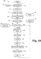
- FIG. 10 illustrates a schematic flow diagram of the exemplary process 600.
- the control assembly 460 may operate in a sleep mode in which it supplies a reduced amount of power to the credential reader assembly 260.
- the process 600 may begin with an operation 610 in which the presence of a user is detected. The presence may, for example, be detected in response to an awakening event or input 611 such as, for example, as detected by the proximity sensor 268.
- the process 600 may continue to an operation 612 which includes waking up the credential reader assembly 260, for example, by providing the credential reader assembly 260 with an increased amount of power via the first strip 358.
- the operation 612 may further include providing an indication to the user that the credential reader assembly 260 is operational such as, for example, by illuminating the LED 268 with a first color.
- the process 600 may then proceed to an operation 614 which includes reading the credential 210.
- the credential reader 264 may attempt to read the smart card 212, and then attempt to read the proximity card 214 if no smart card 212 is detected. In other forms, the credential reader 264 may attempt to read the proximity card 214 first, or may attempt to read both the smart card 212 and proximity card 214 contemporaneously.
- the process 600 may proceed to an operation 616 which includes transmitting credential data 618 from the credential reader assembly 260 to the control assembly 460 such as, for example, via the first strip 358.
- the process 600 may then proceed to an operation 620 which includes comparing the credential data 618 to one or more authorized credentials 622, and then determining whether the credential data 618 matches one of the authorized credentials 622.
- Data relating to one or more authorized credentials 622 may be stored on internal memory of the control assembly 460 such as, for example, the above-described memory 506.
- the data relating to the authorized credentials 622 may be provided to the control assembly 460 from an external source such as, for example, via the wireless transceiver 464.
- the operation 620 yields a negative result 620N.
- the process 600 may reactivate the sleep mode in an operation 626 such as, for example, after waiting a predetermined amount of time t 0 in an operation 624.
- the process 600 may further include providing an indication to the user that the credential 210 is not authorized such as, for example, by illuminating the LED 268 with a second color.
- the operation 620 yields a positive result 620Y.
- the process 600 may continue to an operation 630 in which the controller 465 issues a first signal 632 to at least the actuator 390.
- the first signal 632 may also be sent to the credential reader assembly 260, and the credential reader assembly 260 may provide an indication to the user that the credential 210 is authorized.
- the indication may include illuminating the LED 268 with a third color.
- the actuator 390 performs an operation 634 which includes moving the locking member 380 from the locking position to the unlocking position.
- the process 600 may proceed to an operation 640 in which the controller 465 may issue a second signal 642 to at least the actuator 390.
- the actuator 390 performs an operation 644 which includes moving the locking member 380 from the unlocking position to the locking position.
- the second signal 642 may also be sent to the credential reader assembly 260, and the credential reader assembly 260 may provide an indication to the user that the lockset 100 is transitioning to the locked state.
- the indication may include illuminating the LED 268 with the first color.
- the process 600 may proceed to the operation 626 and reactivate the sleep mode such as, for example, after the predetermined time t 0 has elapsed in the operation 624. While the illustrated process 600 includes various operations to provide the lockset 100 with a sleep mode, the lockset 100 need not necessarily include a sleep mode. In such embodiments, various operations, such as the operations 610, 612, 624, and 626, may be omitted.
- the illustrated actuator 390 includes a rotary motor 391.
- the first signal 632 may include power of a first polarity
- the second signal 642 may include power of an inverted polarity.
- the motor 391 may rotate in a first direction in response to the first signal 632, and may rotate in an opposite direction in response to the second signal 642.
- one of the first and second signals 632, 642 may include power being supplied to the actuator 390, and the other of first and second signals 632, 642 may include power being removed from the actuator 390.
- the first signal 632 may include supplying power to the actuator 390.
- the locking member 380 may be biased to the locking position such that when the solenoid is unpowered, the lockset 100 is in the locked state.
Landscapes
- Engineering & Computer Science (AREA)
- Structural Engineering (AREA)
- Manufacturing & Machinery (AREA)
- Physics & Mathematics (AREA)
- General Physics & Mathematics (AREA)
- Lock And Its Accessories (AREA)
Claims (12)
- Schlosssatz (100), umfassend:eine äußere Baugruppe (200), die zur Montage an einer äußeren Fläche (82) einer Tür (80) konfiguriert ist, die eine standardmäßige Türausführung mit einer standardmäßigen Querbohrung (92) und einem Paar standardmäßiger Befestigungsbohrungen (96) aufweist, die auf gegenüberliegenden Seiten der standardmäßigen Querbohrung (92) angeordnet sind, wobei die äußere Baugruppe Folgendes umfasst:einen äußeren Beschlag (220);einen äußeren Federkäfig (240), der in dem äußeren Beschlag (220) untergebracht ist;eine äußere Spindel (250), die drehbar an dem äußeren Federkäfig (240) montiert ist und sich durch den äußeren Beschlag hindurch erstreckt; undeine äußere Rückplatte (270), die mit dem äußeren Beschlag (220) gekoppelt ist und den äußeren Federkäfig (240) und den Multi-Tech-Berechtigungsnachweisleser innerhalb des äußeren Beschlags (220) hält;eine innere Baugruppe (400), die zur Montage an einer inneren Fläche (84) der Tür konfiguriert ist, wobei die innere Baugruppe Folgendes umfasst:einen inneren Beschlag (420);eine Steueranordnung (460);einen inneren Federkäfig (440), der in dem inneren Beschlag (420) untergebracht ist;eine innere Spindel (450), die drehbar an dem inneren Federkäfig (440) montiert ist und sich durch den inneren Beschlag (420) hindurch erstreckt; undeine innere Rückplatte (470), die mit dem inneren Beschlag (420) gekoppelt ist und den inneren Federkäfig (440) innerhalb des inneren Beschlags hält;eine zentrale Baugruppe (300), die zur Montage an der Tür (80) der standardisierten Türausführung konfiguriert ist, wobei die zentrale Baugruppe (300) Folgendes umfasst:ein Gehäuse (310), das zur Montage in der standardmäßigen Querbohrung (92) konfiguriert ist und eine Außenfläche aufweist, die einen Kanal (312) definiert, der sich in einer Längsrichtung erstreckt, und wobei sich die erste Vielzahl von Drähten entlang des Kanals (312) erstreckt;ein Verriegelungselement (380) mit einer Entriegelungsposition und einer Verriegelungsposition; undein elektronisches Stellglied (390) in Verbindung mit der Steueranordnung (460) über eine zweite Vielzahl von Drähten, wobei die Steuerung so konfiguriert ist, dass das Signal über mindestens einen Draht aus der zweiten Vielzahl von Drähten abgegeben wird, und wobei das elektromechanische Stellglied (390) so konfiguriert ist, dass das Verriegelungselement als Reaktion auf das Signal zwischen der Verriegelungsposition und der Entwicklungsposition bewegt wird; undeinen Retraktor (340), der verschiebbar an dem Gehäuse (310) montiert und so konfiguriert ist, dass er sich als Reaktion auf eine Drehung der inneren Spindel seitlich bewegt;wobei, wenn das Verriegelungselement (380) sich in der Entriegelungsposition befindet, eine Drehung der äußeren Spindel (250) betätigt werden kann, um den Retraktor (340) seitlich zu bewegen; undwobei, wenn das Verriegelungselement (380) sich in der Entriegelungsposition befindet, die äußere Spindel (250) nicht betätigbar ist, um den Retraktor (340) seitlich zu bewegen;ein Paar von Pfosten (244), die sich in Längsrichtung von entweder dem äußeren Federkäfig (240) oder von dem inneren Federkäfig (440) aus erstrecken, wobei die beiden Pfosten (244) so konfiguriert sind, dass sie in den beiden standardmäßigen Befestigungsbohrungen (96) aufgenommen werden können; undein Paar von Befestigungselementen (110) die sich in Längsrichtung von dem anderen von dem äußeren Federkäfig (240 und dem inneren Federkäfig (440) aus erstrecken; wobei jedes Befestigungselement (110) mit einem entsprechenden der Pfosten (244) im Eingriff steht,
dadurch gekennzeichnet, dassdie äußere Baugruppe (200) ferner ein äußeres Fenster (230), das an dem äußeren Beschlag (220) angebracht ist, und eine zum Lesen des Berechtigungsnachweises vorgesehene Anordnung (260) umfasst, die einen Multi-Tech-Berechtigungsnachweisleser enthält, der in dem äußeren Beschlag (220) positioniert und zu dem äußeren Fenster (230) ausgerichtet ist, wobei der Multi-Tech-Berechtigungsnachweisleser zum Lesen eines Berechtigungsnachweises (210) über jedes von einem ersten Protokoll und von einem zweiten Protokoll und zum Übertragen von Daten in Bezug auf den Berechtigungsnachweis (210) als Reaktion auf das Lesen des Berechtigungsnachweises (210) betätigbar ist; undwobei die Steueranordnung (460) in dem inneren Beschlag (420) untergebracht ist und über eine Vielzahl von Drähten mit der zum Lesen des Berechtigungsnachweis vorgesehenen Anordnung (260) in Verbindung steht, wobei die Steueranordnung (460) eine Steuerung enthält, die zum Empfangen der Daten von dem Berechtigungsnachweis so konfiguriert ist, um die Daten zum Berechtigungsnachweis mit einem autorisierten Berechtigungsnachweis zu vergleichen und ein Signal als Antwort auf die verglichenen Daten zum Berechtigungsnachweis auszugeben, wobei die innere Rückplatte (470) auch die Steuerungsanordnung (460) innerhalb des inneren Beschlags (420) hält. - Schlosssatz nach Anspruch 1, wobei die zentrale Baugruppe (300) ferner Folgendes umfasst:eine innere Antriebsspindel (330) die drehbar an dem Gehäuse (310) montiert und drehbar mit der inneren Spindel gekoppelt ist, wobei der Retraktor (340) so konfiguriert ist, dass er sich als Reaktion auf die Drehung der inneren Antriebsspindel (330) seitlich bewegt; undeine äußere Antriebsspindel (320), die drehbar in dem Gehäuse (310) montiert ist, wobei der Retraktor (340) ferner so konfiguriert ist, dass er sich als Reaktion auf die Drehung der äußeren Antriebsspindel (320) seitlich bewegt; und wobei, wenn sich das Verriegelungselement (380) in der Entriegelungsposition befindet, die äußere Antriebsspindel (320) drehbar mit der äußeren Spindel (250) gekoppelt ist undwobei, wenn sich das Verriegelungselement (380) in der Verriegelungsposition befindet, die äußere Antriebsspindel (320) von der äußeren Spindel (250) drehbar entkoppelt ist.
- Schlosssatz nach Anspruch 2, wobei die zentrale Baugruppe (300) ferner eine hülsenförmige Spindel (370) umfasst, die drehbar mit der äußeren Spindel (250) gekoppelt ist; und
wobei, wenn sich das Verriegelungselement (380) in der Entriegelungsposition befindet, die äußere Antriebsspindel (320) in Rotationsrichtung mit der hülsenförmigen Spindel (370) gekoppelt ist; und
wobei, wenn sich das Verriegelungselement (380) in der Verriegelungsposition befindet, die äußere Antriebsspindel (320) in Rotationsrichtung von der hülsenförmige in Spindel (370) entkoppelt ist. - Schlosssatz nach Anspruch 1, ferner umfassend:einen Kabelstrang (350), umfassend einen ersten Streifen (358) mit der ersten Vielzahl von Drähten, einen zweiten Streifen (359) mit der zweiten Vielzahl von Drähten, einen äußeren Stecker (352), der mit der zum Lesen des Berechtigungsnachweises dienenden Anordnung (260) verbunden ist, einen inneren Stecker (354), der mit der Steueranordnung (460) in Eingriff steht, und einen Stellgliedstecker (356), der mit dem elektromechanischen Stellglied (390) in Eingriff steht; undwobei der erste Streifen (358) den äußeren Stecker (352) und den inneren Stecker (354) miteinander verbindet, undwobei der zweite Streifen (359) den inneren Stecker (354) und den Stellgliedstecker (356) miteinander verbindet.
- Schlosssatz nach Anspruch 4,
wobei das Gehäuse (310) ferner ein Paar von Flanschen (315) umfasst, die den Kanal (312) teilweise einschließen; und
wobei der Abstand zwischen den Flanschen (315) kleiner als eine Breite des ersten Streifens (358) ist. - Schlosssatz nach einem der vorhergehenden Ansprüche, wobei der äußere Federkäfig (240) eine Lippe (245) umfasst, die an der äußeren Rückplatte (270) anliegt;
wobei die äußere Rückplatte (270) eine Öffnung (272) aufweist, die zu der Lippe (245) ausgerichtet ist; und
wobei sich die erste Vielzahl von Drähten durch die Öffnung (272) hindurch erstreckt. - Schlosssatz nach Anspruch 6, wobei der innere Federkäfig (440) eine zweite Lippe (445) umfasst, die an der inneren Rückplatte (470) anliegt;
wobei die innere Rückplatte (470) eine zweite Öffnung (474) aufweist, die zu der zweiten Lippe (445) ausgerichtet ist; und
wobei sich die erste Vielzahl von Drähten und die zweite Vielzahl von Drähten durch die zweite Öffnung (474) hindurch erstrecken. - Schlosssatz nach Anspruch 1,
wobei die innere Rückplatte (470) ein Paar von Stollen (476) enthält, die die innere Rückplatte drehbar mit dem Gehäuse (310) koppelt. - Schlosssatz nach einem der vorhergehenden Ansprüche, wobei die innere Baugruppe (400) ferner ein inneres Fenster (430) umfasst, das an dem inneren Beschlag (420) angebracht ist;
wobei die Steueranordnung ferner einen drahtlosen Sendeempfänger (464) umfasst, der im Wesentlichen zu dem inneren Fenster (430) ausgerichtet ist; und
wobei die Steueranordnung (460) so konfiguriert ist, dass sie drahtlos mit einem externen Gerät über den drahtlosen Sendeempfänger (464) kommunizieren kann. - Schlosssatz nach einem der vorhergehenden Ansprüche, ferner umfassend ein Behältnis (482), das in dem inneren Beschlag (420) untergebracht ist, und einen Draht, der elektrisch mit der Steueranordnung (460) gekoppelt ist, wobei das Behältnis (482) so konfiguriert ist, dass es eine Energiespeichervorrichtung (484) aufnehmen kann, und wobei der Draht so konfiguriert ist, dass er die Steueranordnung (460) elektrisch mit der Energiespeichervorrichtung (484) koppelt.
- Schlosssatz nach Anspruch 10, ferner umfassend eine Energiespeichervorrichtung (484), die in das Behältnis (482) eingesetzt ist und elektrisch mit der Steueranordnung (460) gekoppelt ist.
- Schlosssatz nach einem der vorhergehenden Ansprüche, wobei der äußere Federkäfig (240) ein erstes Eingriffsteil umfasst;
wobei der äußere Beschlag (220) ein zweites Eingriffsteil umfasst; und
wobei das erste und das zweite Eingriffsteil miteinander in Eingriff stehen und eine Drehung des äußeren Beschlags (220) relativ zu dem äußeren Federkäfig (240) verhindern.
Priority Applications (1)
| Application Number | Priority Date | Filing Date | Title |
|---|---|---|---|
| EP21167012.0A EP3901396B1 (de) | 2014-11-21 | 2015-11-23 | Elektromechanischer schlosssatz |
Applications Claiming Priority (2)
| Application Number | Priority Date | Filing Date | Title |
|---|---|---|---|
| US14/550,477 US9562370B2 (en) | 2014-11-21 | 2014-11-21 | Electromechanical lockset |
| PCT/US2015/062149 WO2016081935A1 (en) | 2014-11-21 | 2015-11-23 | Electromechanical lockset |
Related Child Applications (1)
| Application Number | Title | Priority Date | Filing Date |
|---|---|---|---|
| EP21167012.0A Division EP3901396B1 (de) | 2014-11-21 | 2015-11-23 | Elektromechanischer schlosssatz |
Publications (3)
| Publication Number | Publication Date |
|---|---|
| EP3221535A1 EP3221535A1 (de) | 2017-09-27 |
| EP3221535A4 EP3221535A4 (de) | 2018-06-13 |
| EP3221535B1 true EP3221535B1 (de) | 2021-04-07 |
Family
ID=56009663
Family Applications (2)
| Application Number | Title | Priority Date | Filing Date |
|---|---|---|---|
| EP21167012.0A Active EP3901396B1 (de) | 2014-11-21 | 2015-11-23 | Elektromechanischer schlosssatz |
| EP15861631.8A Active EP3221535B1 (de) | 2014-11-21 | 2015-11-23 | Elektromechanischer schlosssatz |
Family Applications Before (1)
| Application Number | Title | Priority Date | Filing Date |
|---|---|---|---|
| EP21167012.0A Active EP3901396B1 (de) | 2014-11-21 | 2015-11-23 | Elektromechanischer schlosssatz |
Country Status (7)
| Country | Link |
|---|---|
| US (4) | US9562370B2 (de) |
| EP (2) | EP3901396B1 (de) |
| CN (1) | CN107208430B (de) |
| CA (1) | CA2968671C (de) |
| MX (1) | MX392590B (de) |
| SA (1) | SA517381577B1 (de) |
| WO (1) | WO2016081935A1 (de) |
Families Citing this family (30)
| Publication number | Priority date | Publication date | Assignee | Title |
|---|---|---|---|---|
| US9879445B2 (en) * | 2014-05-02 | 2018-01-30 | Schlage Lock Company Llc | Status-indicating cylindrical lock assembly |
| US9562370B2 (en) | 2014-11-21 | 2017-02-07 | Schlage Lock Company Llc | Electromechanical lockset |
| CA3236029A1 (en) | 2015-04-14 | 2016-10-14 | Hanchett Entry Systems, Inc. | Power controller for a door lock and method of conserving power |
| WO2017184507A1 (en) * | 2016-04-18 | 2017-10-26 | Spectrum Brands, Inc. | Electronic lock with wireless exterior to interior door communication |
| US10494836B2 (en) * | 2016-09-07 | 2019-12-03 | Sargent Manufacturing Company | Bored lock occupancy indicator |
| US11377875B2 (en) | 2016-09-19 | 2022-07-05 | Level Home, Inc. | Deadbolt position sensing |
| TWI745456B (zh) | 2016-10-19 | 2021-11-11 | 美商貝斯特艾瑟斯解決方案股份有限公司 | 電機式鎖芯裝置、系統及操作電機式鎖芯裝置之方法 |
| TWM543909U (zh) * | 2016-12-19 | 2017-06-21 | I-Tek Metal Manufacturing Co Ltd | 模組化電子式門鎖 |
| US10267063B2 (en) * | 2016-12-19 | 2019-04-23 | I-Tek Metal Mfg. Co., Ltd. | Electric door lock |
| CN107435467B (zh) * | 2017-07-27 | 2023-03-17 | 深圳家卫士科技有限公司 | 一种防盗门智能锁 |
| WO2019051337A1 (en) | 2017-09-08 | 2019-03-14 | Dormakaba Usa Inc. | CENTRAL ELECTROMECHANICAL LOCK SECTION |
| US11414889B2 (en) * | 2017-11-21 | 2022-08-16 | Taiwan Colour & Imaging Technology Corporation | Electronic lock apparatus |
| CN112752891B (zh) | 2018-04-13 | 2022-08-05 | 多玛卡巴美国公司 | 机电锁芯 |
| US11466473B2 (en) | 2018-04-13 | 2022-10-11 | Dormakaba Usa Inc | Electro-mechanical lock core |
| US11643845B2 (en) | 2018-09-10 | 2023-05-09 | Spectrum Brands, Inc. | Locking assembly with spring mechanism |
| USD885865S1 (en) * | 2019-01-16 | 2020-06-02 | SimpliSafe, Inc. | Door lock |
| USD887248S1 (en) * | 2019-01-16 | 2020-06-16 | SimpliSafe, Inc. | Door lock |
| USD887249S1 (en) * | 2019-01-16 | 2020-06-16 | SimpliSafe, Inc. | Door lock |
| USD888537S1 (en) * | 2019-01-16 | 2020-06-30 | SimpliSafe, Inc. | Door lock |
| US10657795B1 (en) | 2019-02-01 | 2020-05-19 | SimpliSafe, Inc. | Alarm system with first responder code for building access |
| US10794085B2 (en) | 2019-02-18 | 2020-10-06 | Schlage Lock Company Llc | Internet of things lock module |
| US11639617B1 (en) | 2019-04-03 | 2023-05-02 | The Chamberlain Group Llc | Access control system and method |
| US11933092B2 (en) | 2019-08-13 | 2024-03-19 | SimpliSafe, Inc. | Mounting assembly for door lock |
| US11072944B2 (en) * | 2019-08-29 | 2021-07-27 | Fu Chang Locks Mfg. Corp. | Electronic lock |
| CA3158971A1 (en) * | 2019-11-22 | 2021-05-27 | Alan Uyeda | Sealing of an electronic lock |
| CN111197431A (zh) * | 2019-12-30 | 2020-05-26 | 厦门美科物联科技有限公司 | 一种新型电子锁结构 |
| CA3198381A1 (en) * | 2020-10-06 | 2022-04-14 | Assa Abloy Access And Egress Hardware Group, Inc. | Electronic locking device |
| CN112302423B (zh) * | 2020-10-30 | 2023-06-09 | 广州朗国电子科技股份有限公司 | 一种免插线的门锁固定结构 |
| CA3230147A1 (en) * | 2021-09-09 | 2023-03-16 | Assa Abloy Americas Residential Inc. | Electronic lock assembly and method of installing the same |
| CN117306952B (zh) * | 2023-10-30 | 2025-08-01 | 浙江瀚运五金有限公司 | 一种锁具和门锁 |
Family Cites Families (35)
| Publication number | Priority date | Publication date | Assignee | Title |
|---|---|---|---|---|
| US3559430A (en) * | 1968-08-08 | 1971-02-02 | Russell S Waller | Locking mechanism |
| US5421178A (en) | 1993-01-19 | 1995-06-06 | Best Lock Corporation | Motorized lock actuator for cylindrical lockset |
| US5931430A (en) * | 1996-04-25 | 1999-08-03 | Best Lock Corporation | Motor assembly for cylindrical lockset |
| US5782118A (en) | 1996-07-16 | 1998-07-21 | Schlage Lock Company | Lockset with motorized system for locking and unlocking |
| CN1268616A (zh) * | 1999-03-29 | 2000-10-04 | 深圳市兆凯电子有限公司 | 电脑控制机械电子混合门锁 |
| ES2189571B2 (es) | 1999-12-31 | 2004-06-01 | Escudos Kala Internacional, S.L. | Mecanismo de embrague para cerraduras electronicas. |
| US6418765B1 (en) | 2000-07-03 | 2002-07-16 | Ming-Hsiang Chiu | Motor-driven lock |
| JP2004076277A (ja) * | 2002-08-09 | 2004-03-11 | Yunirekku:Kk | 施錠装置 |
| US20060114099A1 (en) | 2003-03-21 | 2006-06-01 | Deng Sheng B | Door lock and operation mechanism |
| US7984631B2 (en) * | 2003-12-22 | 2011-07-26 | Yale Security Inc. | Modular escutcheon |
| US6935149B1 (en) * | 2004-03-23 | 2005-08-30 | Fu Chang Peng | Electric door lock openable by key |
| US7152891B2 (en) | 2004-09-09 | 2006-12-26 | Newfrey Llc | Field-reversible locking mechanism |
| US20060226948A1 (en) * | 2005-04-08 | 2006-10-12 | Computerized Security Systems | Door lock with RFID key |
| US20070163863A1 (en) * | 2006-01-17 | 2007-07-19 | Computerized Security Systems, Inc. | Water resistant keycard reader assembly for an electronic lock |
| TWM327398U (en) * | 2007-07-27 | 2008-02-21 | Tong Lung Metal Ind Co Ltd | Clutch mechanism for electric lock |
| NZ615317A (en) | 2008-06-27 | 2014-12-24 | Schlage Lock Co | Electronic door lock with modular components |
| US8141400B2 (en) | 2009-04-10 | 2012-03-27 | Emtek Products, Inc. | Keypad lockset |
| US20100307206A1 (en) * | 2009-06-08 | 2010-12-09 | Harrow Products Llc | Electronic door lock for reduced power consumption |
| CA2770691C (en) * | 2009-08-20 | 2018-10-09 | Sargent Manufacturing Company | Locking device with integrated circuit board |
| EP2494132A1 (de) * | 2009-10-28 | 2012-09-05 | UTC Fire & Security Corporation | Drahtlosfähige antenne für eine sicherheitstür |
| US8621900B2 (en) | 2010-04-22 | 2014-01-07 | Tong Lung Metal Industry Co., Ltd. | Electric door lock |
| US8356499B2 (en) | 2010-07-08 | 2013-01-22 | Fu Chang Locks Mfg Corp. | Electric lock |
| US8051689B1 (en) * | 2010-11-11 | 2011-11-08 | I-Tek Metal Mfg. Co., Ltd. | Cylindrical lock with automatic electronic locking function |
| US8690205B2 (en) * | 2011-02-21 | 2014-04-08 | Yale Security Inc. | Door lockset |
| KR102206369B1 (ko) * | 2012-10-23 | 2021-01-22 | 스펙트럼 브랜즈, 인크. | 소프트웨어 기반 자동 멀티-무선 프로파일 검출 및 설정을 갖는 전자식 잠금장치 |
| US9273489B2 (en) | 2012-12-18 | 2016-03-01 | Stanley Security Solutions, Inc. | Lock assembly having motor inside interior operator handle |
| CA2903911C (en) * | 2013-03-11 | 2022-05-17 | Spectrum Brands, Inc. | Electronic deadbolt |
| US9725928B2 (en) * | 2013-03-15 | 2017-08-08 | Schlage Lock Company Llc | Adjustment plate gauge insert and adapter for hands-free lock installation |
| US9487971B2 (en) * | 2013-03-15 | 2016-11-08 | Spectrum Brands, Inc. | Electro-mechanical locks with bezel turning function |
| US9199575B2 (en) * | 2013-11-27 | 2015-12-01 | GM Global Technology Operations LLC | Vehicle lamp assembly with flexible lens |
| US9790713B2 (en) | 2014-02-25 | 2017-10-17 | Schlage Lock Company Llc | Simplified lever handing apparatus |
| US10047544B2 (en) * | 2014-04-17 | 2018-08-14 | Tlhm Co., Ltd. | Transmission device of electronic lock |
| US9879445B2 (en) * | 2014-05-02 | 2018-01-30 | Schlage Lock Company Llc | Status-indicating cylindrical lock assembly |
| TWI544131B (zh) * | 2014-08-06 | 2016-08-01 | 台灣福興工業股份有限公司 | 把手裝置及其復位機構 |
| US9562370B2 (en) * | 2014-11-21 | 2017-02-07 | Schlage Lock Company Llc | Electromechanical lockset |
-
2014
- 2014-11-21 US US14/550,477 patent/US9562370B2/en active Active
-
2015
- 2015-11-23 WO PCT/US2015/062149 patent/WO2016081935A1/en not_active Ceased
- 2015-11-23 CA CA2968671A patent/CA2968671C/en active Active
- 2015-11-23 EP EP21167012.0A patent/EP3901396B1/de active Active
- 2015-11-23 CN CN201580074182.XA patent/CN107208430B/zh active Active
- 2015-11-23 EP EP15861631.8A patent/EP3221535B1/de active Active
- 2015-11-23 MX MX2017006647A patent/MX392590B/es unknown
-
2017
- 2017-02-07 US US15/426,742 patent/US10370870B2/en active Active
- 2017-05-21 SA SA517381577A patent/SA517381577B1/ar unknown
-
2019
- 2019-08-06 US US16/533,333 patent/US10871008B2/en active Active
-
2020
- 2020-12-22 US US17/131,003 patent/US12565795B2/en active Active
Non-Patent Citations (1)
| Title |
|---|
| None * |
Also Published As
| Publication number | Publication date |
|---|---|
| US20160145898A1 (en) | 2016-05-26 |
| US12565795B2 (en) | 2026-03-03 |
| EP3901396A1 (de) | 2021-10-27 |
| US20200032550A1 (en) | 2020-01-30 |
| CA2968671A1 (en) | 2016-05-26 |
| EP3901396B1 (de) | 2026-02-18 |
| WO2016081935A1 (en) | 2016-05-26 |
| EP3221535A4 (de) | 2018-06-13 |
| CA2968671C (en) | 2019-04-02 |
| EP3221535A1 (de) | 2017-09-27 |
| SA517381577B1 (ar) | 2020-11-08 |
| US20170145714A1 (en) | 2017-05-25 |
| US10871008B2 (en) | 2020-12-22 |
| MX392590B (es) | 2025-03-21 |
| CN107208430B (zh) | 2020-05-19 |
| US10370870B2 (en) | 2019-08-06 |
| CN107208430A (zh) | 2017-09-26 |
| US20210285257A1 (en) | 2021-09-16 |
| US9562370B2 (en) | 2017-02-07 |
| MX2017006647A (es) | 2018-05-02 |
Similar Documents
| Publication | Publication Date | Title |
|---|---|---|
| US12565795B2 (en) | Electromechanical lockset | |
| US20230258024A1 (en) | Motorized electric strike | |
| US20210174620A1 (en) | Electronic lock with clutch | |
| US10858862B2 (en) | Lockset with powered retraction | |
| US20180225899A1 (en) | Access control device commissioning | |
| AU2023206922B2 (en) | Lockset assembly and installation | |
| US12448815B2 (en) | Bolt actuation assembly | |
| US20250376875A1 (en) | Lock module with mechanical override | |
| JP6494500B2 (ja) | 錠装置のベース部材およびそれを用いた錠装置 | |
| US20250223839A1 (en) | Electrified latch assembly | |
| US20230167657A1 (en) | Lock with override mechanism | |
| US20180047231A1 (en) | History management system of electronic locking device | |
| JP6445951B2 (ja) | 電子式シリンダー錠 |
Legal Events
| Date | Code | Title | Description |
|---|---|---|---|
| STAA | Information on the status of an ep patent application or granted ep patent |
Free format text: STATUS: THE INTERNATIONAL PUBLICATION HAS BEEN MADE |
|
| PUAI | Public reference made under article 153(3) epc to a published international application that has entered the european phase |
Free format text: ORIGINAL CODE: 0009012 |
|
| STAA | Information on the status of an ep patent application or granted ep patent |
Free format text: STATUS: REQUEST FOR EXAMINATION WAS MADE |
|
| 17P | Request for examination filed |
Effective date: 20170621 |
|
| AK | Designated contracting states |
Kind code of ref document: A1 Designated state(s): AL AT BE BG CH CY CZ DE DK EE ES FI FR GB GR HR HU IE IS IT LI LT LU LV MC MK MT NL NO PL PT RO RS SE SI SK SM TR |
|
| AX | Request for extension of the european patent |
Extension state: BA ME |
|
| RIN1 | Information on inventor provided before grant (corrected) |
Inventor name: OHL, JAMES, D. Inventor name: KINCAID, RYAN, C. Inventor name: EVENSON, JOHN Inventor name: BAUMGARTE, JOSEPH, WAYNE Inventor name: DEXTER, MATTHEW Inventor name: WHITE, RICHARD, A. |
|
| DAV | Request for validation of the european patent (deleted) | ||
| DAX | Request for extension of the european patent (deleted) | ||
| A4 | Supplementary search report drawn up and despatched |
Effective date: 20180514 |
|
| RIC1 | Information provided on ipc code assigned before grant |
Ipc: E05B 41/00 20060101ALN20180508BHEP Ipc: E05B 63/10 20060101ALI20180508BHEP Ipc: E05B 49/02 20060101ALI20180508BHEP Ipc: E05B 15/00 20060101AFI20180508BHEP Ipc: E05B 47/00 20060101ALI20180508BHEP Ipc: G07C 9/00 20060101ALI20180508BHEP Ipc: E05B 47/06 20060101ALI20180508BHEP |
|
| STAA | Information on the status of an ep patent application or granted ep patent |
Free format text: STATUS: EXAMINATION IS IN PROGRESS |
|
| 17Q | First examination report despatched |
Effective date: 20190116 |
|
| GRAJ | Information related to disapproval of communication of intention to grant by the applicant or resumption of examination proceedings by the epo deleted |
Free format text: ORIGINAL CODE: EPIDOSDIGR1 |
|
| GRAP | Despatch of communication of intention to grant a patent |
Free format text: ORIGINAL CODE: EPIDOSNIGR1 |
|
| GRAP | Despatch of communication of intention to grant a patent |
Free format text: ORIGINAL CODE: EPIDOSNIGR1 |
|
| STAA | Information on the status of an ep patent application or granted ep patent |
Free format text: STATUS: GRANT OF PATENT IS INTENDED |
|
| RIC1 | Information provided on ipc code assigned before grant |
Ipc: E05B 41/00 20060101ALN20200703BHEP Ipc: E05B 15/00 20060101AFI20200703BHEP Ipc: E05B 47/00 20060101ALI20200703BHEP Ipc: E05B 63/10 20060101ALI20200703BHEP Ipc: E05B 47/06 20060101ALI20200703BHEP Ipc: G07C 9/00 20200101ALI20200703BHEP Ipc: E05B 49/02 20060101ALI20200703BHEP |
|
| RIC1 | Information provided on ipc code assigned before grant |
Ipc: E05B 41/00 20060101ALN20200715BHEP Ipc: E05B 63/10 20060101ALI20200715BHEP Ipc: E05B 47/00 20060101ALI20200715BHEP Ipc: E05B 15/00 20060101AFI20200715BHEP Ipc: G07C 9/00 20200101ALI20200715BHEP Ipc: E05B 47/06 20060101ALI20200715BHEP Ipc: E05B 49/02 20060101ALI20200715BHEP |
|
| RIC1 | Information provided on ipc code assigned before grant |
Ipc: E05B 49/02 20060101ALI20200717BHEP Ipc: E05B 47/00 20060101ALI20200717BHEP Ipc: E05B 15/00 20060101AFI20200717BHEP Ipc: G07C 9/00 20200101ALI20200717BHEP Ipc: E05B 63/10 20060101ALI20200717BHEP Ipc: E05B 41/00 20060101ALN20200717BHEP Ipc: E05B 47/06 20060101ALI20200717BHEP |
|
| INTG | Intention to grant announced |
Effective date: 20200804 |
|
| GRAJ | Information related to disapproval of communication of intention to grant by the applicant or resumption of examination proceedings by the epo deleted |
Free format text: ORIGINAL CODE: EPIDOSDIGR1 |
|
| STAA | Information on the status of an ep patent application or granted ep patent |
Free format text: STATUS: EXAMINATION IS IN PROGRESS |
|
| GRAP | Despatch of communication of intention to grant a patent |
Free format text: ORIGINAL CODE: EPIDOSNIGR1 |
|
| STAA | Information on the status of an ep patent application or granted ep patent |
Free format text: STATUS: GRANT OF PATENT IS INTENDED |
|
| INTC | Intention to grant announced (deleted) | ||
| RIC1 | Information provided on ipc code assigned before grant |
Ipc: E05B 15/00 20060101AFI20200925BHEP Ipc: E05B 47/00 20060101ALI20200925BHEP Ipc: E05B 63/10 20060101ALI20200925BHEP Ipc: E05B 47/06 20060101ALI20200925BHEP Ipc: E05B 41/00 20060101ALN20200925BHEP Ipc: G07C 9/00 20200101ALI20200925BHEP Ipc: E05B 49/02 20060101ALI20200925BHEP |
|
| INTG | Intention to grant announced |
Effective date: 20201020 |
|
| GRAS | Grant fee paid |
Free format text: ORIGINAL CODE: EPIDOSNIGR3 |
|
| GRAA | (expected) grant |
Free format text: ORIGINAL CODE: 0009210 |
|
| STAA | Information on the status of an ep patent application or granted ep patent |
Free format text: STATUS: THE PATENT HAS BEEN GRANTED |
|
| AK | Designated contracting states |
Kind code of ref document: B1 Designated state(s): AL AT BE BG CH CY CZ DE DK EE ES FI FR GB GR HR HU IE IS IT LI LT LU LV MC MK MT NL NO PL PT RO RS SE SI SK SM TR |
|
| REG | Reference to a national code |
Ref country code: GB Ref legal event code: FG4D |
|
| REG | Reference to a national code |
Ref country code: AT Ref legal event code: REF Ref document number: 1379883 Country of ref document: AT Kind code of ref document: T Effective date: 20210415 Ref country code: CH Ref legal event code: EP |
|
| REG | Reference to a national code |
Ref country code: DE Ref legal event code: R096 Ref document number: 602015067918 Country of ref document: DE |
|
| REG | Reference to a national code |
Ref country code: IE Ref legal event code: FG4D |
|
| REG | Reference to a national code |
Ref country code: LT Ref legal event code: MG9D |
|
| REG | Reference to a national code |
Ref country code: NL Ref legal event code: MP Effective date: 20210407 Ref country code: AT Ref legal event code: MK05 Ref document number: 1379883 Country of ref document: AT Kind code of ref document: T Effective date: 20210407 |
|
| PG25 | Lapsed in a contracting state [announced via postgrant information from national office to epo] |
Ref country code: HR Free format text: LAPSE BECAUSE OF FAILURE TO SUBMIT A TRANSLATION OF THE DESCRIPTION OR TO PAY THE FEE WITHIN THE PRESCRIBED TIME-LIMIT Effective date: 20210407 Ref country code: AT Free format text: LAPSE BECAUSE OF FAILURE TO SUBMIT A TRANSLATION OF THE DESCRIPTION OR TO PAY THE FEE WITHIN THE PRESCRIBED TIME-LIMIT Effective date: 20210407 Ref country code: BG Free format text: LAPSE BECAUSE OF FAILURE TO SUBMIT A TRANSLATION OF THE DESCRIPTION OR TO PAY THE FEE WITHIN THE PRESCRIBED TIME-LIMIT Effective date: 20210707 Ref country code: FI Free format text: LAPSE BECAUSE OF FAILURE TO SUBMIT A TRANSLATION OF THE DESCRIPTION OR TO PAY THE FEE WITHIN THE PRESCRIBED TIME-LIMIT Effective date: 20210407 Ref country code: LT Free format text: LAPSE BECAUSE OF FAILURE TO SUBMIT A TRANSLATION OF THE DESCRIPTION OR TO PAY THE FEE WITHIN THE PRESCRIBED TIME-LIMIT Effective date: 20210407 Ref country code: NL Free format text: LAPSE BECAUSE OF FAILURE TO SUBMIT A TRANSLATION OF THE DESCRIPTION OR TO PAY THE FEE WITHIN THE PRESCRIBED TIME-LIMIT Effective date: 20210407 |
|
| PG25 | Lapsed in a contracting state [announced via postgrant information from national office to epo] |
Ref country code: SE Free format text: LAPSE BECAUSE OF FAILURE TO SUBMIT A TRANSLATION OF THE DESCRIPTION OR TO PAY THE FEE WITHIN THE PRESCRIBED TIME-LIMIT Effective date: 20210407 Ref country code: RS Free format text: LAPSE BECAUSE OF FAILURE TO SUBMIT A TRANSLATION OF THE DESCRIPTION OR TO PAY THE FEE WITHIN THE PRESCRIBED TIME-LIMIT Effective date: 20210407 Ref country code: NO Free format text: LAPSE BECAUSE OF FAILURE TO SUBMIT A TRANSLATION OF THE DESCRIPTION OR TO PAY THE FEE WITHIN THE PRESCRIBED TIME-LIMIT Effective date: 20210707 Ref country code: PT Free format text: LAPSE BECAUSE OF FAILURE TO SUBMIT A TRANSLATION OF THE DESCRIPTION OR TO PAY THE FEE WITHIN THE PRESCRIBED TIME-LIMIT Effective date: 20210809 Ref country code: PL Free format text: LAPSE BECAUSE OF FAILURE TO SUBMIT A TRANSLATION OF THE DESCRIPTION OR TO PAY THE FEE WITHIN THE PRESCRIBED TIME-LIMIT Effective date: 20210407 Ref country code: LV Free format text: LAPSE BECAUSE OF FAILURE TO SUBMIT A TRANSLATION OF THE DESCRIPTION OR TO PAY THE FEE WITHIN THE PRESCRIBED TIME-LIMIT Effective date: 20210407 Ref country code: IS Free format text: LAPSE BECAUSE OF FAILURE TO SUBMIT A TRANSLATION OF THE DESCRIPTION OR TO PAY THE FEE WITHIN THE PRESCRIBED TIME-LIMIT Effective date: 20210807 Ref country code: GR Free format text: LAPSE BECAUSE OF FAILURE TO SUBMIT A TRANSLATION OF THE DESCRIPTION OR TO PAY THE FEE WITHIN THE PRESCRIBED TIME-LIMIT Effective date: 20210708 |
|
| REG | Reference to a national code |
Ref country code: DE Ref legal event code: R097 Ref document number: 602015067918 Country of ref document: DE |
|
| PG25 | Lapsed in a contracting state [announced via postgrant information from national office to epo] |
Ref country code: SK Free format text: LAPSE BECAUSE OF FAILURE TO SUBMIT A TRANSLATION OF THE DESCRIPTION OR TO PAY THE FEE WITHIN THE PRESCRIBED TIME-LIMIT Effective date: 20210407 Ref country code: SM Free format text: LAPSE BECAUSE OF FAILURE TO SUBMIT A TRANSLATION OF THE DESCRIPTION OR TO PAY THE FEE WITHIN THE PRESCRIBED TIME-LIMIT Effective date: 20210407 Ref country code: CZ Free format text: LAPSE BECAUSE OF FAILURE TO SUBMIT A TRANSLATION OF THE DESCRIPTION OR TO PAY THE FEE WITHIN THE PRESCRIBED TIME-LIMIT Effective date: 20210407 Ref country code: DK Free format text: LAPSE BECAUSE OF FAILURE TO SUBMIT A TRANSLATION OF THE DESCRIPTION OR TO PAY THE FEE WITHIN THE PRESCRIBED TIME-LIMIT Effective date: 20210407 Ref country code: EE Free format text: LAPSE BECAUSE OF FAILURE TO SUBMIT A TRANSLATION OF THE DESCRIPTION OR TO PAY THE FEE WITHIN THE PRESCRIBED TIME-LIMIT Effective date: 20210407 Ref country code: RO Free format text: LAPSE BECAUSE OF FAILURE TO SUBMIT A TRANSLATION OF THE DESCRIPTION OR TO PAY THE FEE WITHIN THE PRESCRIBED TIME-LIMIT Effective date: 20210407 Ref country code: ES Free format text: LAPSE BECAUSE OF FAILURE TO SUBMIT A TRANSLATION OF THE DESCRIPTION OR TO PAY THE FEE WITHIN THE PRESCRIBED TIME-LIMIT Effective date: 20210406 |
|
| PLBE | No opposition filed within time limit |
Free format text: ORIGINAL CODE: 0009261 |
|
| STAA | Information on the status of an ep patent application or granted ep patent |
Free format text: STATUS: NO OPPOSITION FILED WITHIN TIME LIMIT |
|
| 26N | No opposition filed |
Effective date: 20220110 |
|
| PG25 | Lapsed in a contracting state [announced via postgrant information from national office to epo] |
Ref country code: IS Free format text: LAPSE BECAUSE OF FAILURE TO SUBMIT A TRANSLATION OF THE DESCRIPTION OR TO PAY THE FEE WITHIN THE PRESCRIBED TIME-LIMIT Effective date: 20210807 Ref country code: AL Free format text: LAPSE BECAUSE OF FAILURE TO SUBMIT A TRANSLATION OF THE DESCRIPTION OR TO PAY THE FEE WITHIN THE PRESCRIBED TIME-LIMIT Effective date: 20210407 |
|
| PG25 | Lapsed in a contracting state [announced via postgrant information from national office to epo] |
Ref country code: MC Free format text: LAPSE BECAUSE OF FAILURE TO SUBMIT A TRANSLATION OF THE DESCRIPTION OR TO PAY THE FEE WITHIN THE PRESCRIBED TIME-LIMIT Effective date: 20210407 |
|
| REG | Reference to a national code |
Ref country code: CH Ref legal event code: PL |
|
| PG25 | Lapsed in a contracting state [announced via postgrant information from national office to epo] |
Ref country code: LU Free format text: LAPSE BECAUSE OF NON-PAYMENT OF DUE FEES Effective date: 20211123 Ref country code: BE Free format text: LAPSE BECAUSE OF NON-PAYMENT OF DUE FEES Effective date: 20211130 |
|
| REG | Reference to a national code |
Ref country code: BE Ref legal event code: MM Effective date: 20211130 |
|
| PG25 | Lapsed in a contracting state [announced via postgrant information from national office to epo] |
Ref country code: IE Free format text: LAPSE BECAUSE OF NON-PAYMENT OF DUE FEES Effective date: 20211123 |
|
| PG25 | Lapsed in a contracting state [announced via postgrant information from national office to epo] |
Ref country code: HU Free format text: LAPSE BECAUSE OF FAILURE TO SUBMIT A TRANSLATION OF THE DESCRIPTION OR TO PAY THE FEE WITHIN THE PRESCRIBED TIME-LIMIT; INVALID AB INITIO Effective date: 20151123 |
|
| PG25 | Lapsed in a contracting state [announced via postgrant information from national office to epo] |
Ref country code: CY Free format text: LAPSE BECAUSE OF FAILURE TO SUBMIT A TRANSLATION OF THE DESCRIPTION OR TO PAY THE FEE WITHIN THE PRESCRIBED TIME-LIMIT Effective date: 20210407 |
|
| PG25 | Lapsed in a contracting state [announced via postgrant information from national office to epo] |
Ref country code: LI Free format text: LAPSE BECAUSE OF NON-PAYMENT OF DUE FEES Effective date: 20220701 Ref country code: CH Free format text: LAPSE BECAUSE OF NON-PAYMENT OF DUE FEES Effective date: 20220701 |
|
| PG25 | Lapsed in a contracting state [announced via postgrant information from national office to epo] |
Ref country code: MK Free format text: LAPSE BECAUSE OF FAILURE TO SUBMIT A TRANSLATION OF THE DESCRIPTION OR TO PAY THE FEE WITHIN THE PRESCRIBED TIME-LIMIT Effective date: 20210407 |
|
| PG25 | Lapsed in a contracting state [announced via postgrant information from national office to epo] |
Ref country code: TR Free format text: LAPSE BECAUSE OF FAILURE TO SUBMIT A TRANSLATION OF THE DESCRIPTION OR TO PAY THE FEE WITHIN THE PRESCRIBED TIME-LIMIT Effective date: 20210407 |
|
| PG25 | Lapsed in a contracting state [announced via postgrant information from national office to epo] |
Ref country code: MT Free format text: LAPSE BECAUSE OF FAILURE TO SUBMIT A TRANSLATION OF THE DESCRIPTION OR TO PAY THE FEE WITHIN THE PRESCRIBED TIME-LIMIT Effective date: 20210407 |
|
| PGFP | Annual fee paid to national office [announced via postgrant information from national office to epo] |
Ref country code: DE Payment date: 20251022 Year of fee payment: 11 |
|
| PGFP | Annual fee paid to national office [announced via postgrant information from national office to epo] |
Ref country code: GB Payment date: 20251023 Year of fee payment: 11 |
|
| PGFP | Annual fee paid to national office [announced via postgrant information from national office to epo] |
Ref country code: IT Payment date: 20251022 Year of fee payment: 11 |
|
| PGFP | Annual fee paid to national office [announced via postgrant information from national office to epo] |
Ref country code: FR Payment date: 20251022 Year of fee payment: 11 |