EP3220515A1 - Demountable electric motor - Google Patents
Demountable electric motor Download PDFInfo
- Publication number
- EP3220515A1 EP3220515A1 EP17161871.3A EP17161871A EP3220515A1 EP 3220515 A1 EP3220515 A1 EP 3220515A1 EP 17161871 A EP17161871 A EP 17161871A EP 3220515 A1 EP3220515 A1 EP 3220515A1
- Authority
- EP
- European Patent Office
- Prior art keywords
- housing
- rolling device
- shaft
- electric motor
- centering
- Prior art date
- Legal status (The legal status is an assumption and is not a legal conclusion. Google has not performed a legal analysis and makes no representation as to the accuracy of the status listed.)
- Granted
Links
- 238000005096 rolling process Methods 0.000 claims abstract description 58
- 238000007789 sealing Methods 0.000 claims description 4
- 238000006073 displacement reaction Methods 0.000 claims description 3
- 238000012423 maintenance Methods 0.000 description 5
- 238000000605 extraction Methods 0.000 description 3
- 239000002184 metal Substances 0.000 description 2
- 235000020004 porter Nutrition 0.000 description 2
- 125000006850 spacer group Chemical group 0.000 description 2
- 230000015556 catabolic process Effects 0.000 description 1
- 238000001816 cooling Methods 0.000 description 1
- 238000006731 degradation reaction Methods 0.000 description 1
- 239000004519 grease Substances 0.000 description 1
- 239000000314 lubricant Substances 0.000 description 1
- 230000001050 lubricating effect Effects 0.000 description 1
- 238000000034 method Methods 0.000 description 1
Images


Classifications
-
- H—ELECTRICITY
- H02—GENERATION; CONVERSION OR DISTRIBUTION OF ELECTRIC POWER
- H02K—DYNAMO-ELECTRIC MACHINES
- H02K5/00—Casings; Enclosures; Supports
- H02K5/04—Casings or enclosures characterised by the shape, form or construction thereof
- H02K5/15—Mounting arrangements for bearing-shields or end plates
-
- H—ELECTRICITY
- H02—GENERATION; CONVERSION OR DISTRIBUTION OF ELECTRIC POWER
- H02K—DYNAMO-ELECTRIC MACHINES
- H02K15/00—Methods or apparatus specially adapted for manufacturing, assembling, maintaining or repairing of dynamo-electric machines
- H02K15/0006—Disassembling, repairing or modifying dynamo-electric machines
-
- H—ELECTRICITY
- H02—GENERATION; CONVERSION OR DISTRIBUTION OF ELECTRIC POWER
- H02K—DYNAMO-ELECTRIC MACHINES
- H02K5/00—Casings; Enclosures; Supports
- H02K5/04—Casings or enclosures characterised by the shape, form or construction thereof
- H02K5/16—Means for supporting bearings, e.g. insulating supports or means for fitting bearings in the bearing-shields
- H02K5/173—Means for supporting bearings, e.g. insulating supports or means for fitting bearings in the bearing-shields using bearings with rolling contact, e.g. ball bearings
- H02K5/1732—Means for supporting bearings, e.g. insulating supports or means for fitting bearings in the bearing-shields using bearings with rolling contact, e.g. ball bearings radially supporting the rotary shaft at both ends of the rotor
Definitions
- Electric motors of this type are used in particular for the propulsion of railway vehicles. They are located at the level of bogies and receive electrical power supplied by a current generator or directly supplied by a high-voltage line. They convert this electrical power into mechanical power intended to drive the wheels in rotation, by means of the rotation of a rotor driving a shaft carried by bearings and causing itself to rotate one or more wheels, for example by through a gearbox.
- Rolling bearings of electric motors require regular maintenance, such as a renewal of the lubricating grease or a change of worn rolling parts, in order to avoid a decrease in performance, for example because of a seizing of the bearings, or damage to the engine.
- the disassembly of the rolling devices for their maintenance or replacement generally requires disassembly of the rotor with its shaft to allow the extraction of the bearing. Therefore, the maintenance or replacement time of bearings is important and requires the intervention of qualified personnel and specific handling means.
- the presence of permanent magnets on the rotor makes the operation even more complex, and is a source of accident risk for operators or damage to the engine during handling.
- An object of the invention is thus to provide a bearing device fitted to an electric motor and to disassemble the bearings without requiring disassembly of the rest of the rotating part of the engine.
- the subject of the invention is an electric motor of the aforementioned type, characterized in that the rolling device is movable between a mounting position, in which at least one centering bearing surface of the rolling device bears against at least one centering span of the housing so that the rolling device is fixed to the housing in the mounting position, and a disassembly position, in which the centering bearing surface of the rolling device is arranged opposite a housing cavity and the bearing centering the housing is arranged opposite a cavity of the device of rolling, so that the rolling device is movable in translation along the axis relative to the housing and the shaft, in disassembly position.
- An engine of this type makes it possible to extract the bearing by sliding it along the shaft, without having to disassemble the rotor with its shaft.
- An engine 10 shown on the figure 1 transforms an electrical power into mechanical power by the rotation of a rotor 12 driven by a stator 14 electrically powered.
- the rotor 12 and the stator 14 are separated by an air gap whose width is denoted e.
- the rotor 12 is carried by a shaft 16, itself carried by at least one rolling device 18.
- the motor 10 represented on the figure 1 is schematic and not all elements of it have been represented.
- the motor 10 also comprises, inter alia, a cooling circuit and electrical supply means connected to the stator 14.
- each end flange 22 is closed by the rolling device 18 which comprises a housing 23 containing a rolling bearing 24.
- the shaft 16 carrying the rotor 12 is substantially cylindrical, extending along a longitudinal axis A-A ', and free to rotate with respect to the housing 20, about the axis AA' thanks to the action of the or rolling bearings 24.
- the rolling bearing 24 comprises an inner ring 26 and an outer ring 28 enclosing a plurality of rolling elements 30.
- the inner ring 26 is clamped around the shaft 16, bearing on a shoulder 32 of the shaft 16 which blocks its axial displacement.
- the outer ring 28 is contained in the housing 23, and positioned facing the inner ring 26.
- the rolling elements 30 are metal balls, free to roll in the rail formed by the inner ring 26 and the outer ring 28 with friction reduced by the addition of a lubricant.
- the inner ring is rotatable about the axis AA 'relative to the outer ring.
- the rolling elements 30 are metal cylinders whose axes are parallel to the axis AA 'of the shaft 16.
- the housing 23 is held fixed to the flange 22, bearing on a shoulder 34 of the housing 23, for example by means of screws passing through orifices 36 drilled in the shoulder 34, and engaged in threads 38 of the end flange 22.
- the housing 23 has at least one cavity 40, on a portion of a circumferential contact surface with the flange 22, for example recessed sectors.
- sector recessed we mean that the distance between the wall of the cavity 40 and the axis AA 'is smaller than the distance between the axis AA' and the circumferential wall of the rest of the housing 23.
- the flange 22 has at least one cavity 42, for example recessed areas, on a part of the circumferential contact surface with the housing 23.
- this time means that the distance between the wall of the cavity 42 and the axis AA 'is larger than the distance between the axis AA' and the circumferential wall of the remainder of the flange 22.
- the housing 23 also has at least one centering surface 44 on the remainder of the circumferential contact surface with the flange 22, and the flange 22 likewise has at least one centering surface 46 on the remainder of the circumferential contact surface. with the housing 23.
- the distance between the axis AA 'and the centering surface 44 of the housing 23 is substantially equal to the distance between the axis AA' and the centering surface 46 of the flange 22.
- This distance between the axis AA 'and the centering bearings 44, 46 is greater than the distance between the axis AA' and the wall of the cavity 40 of the housing 23, and less than the distance between the axis AA 'and the wall of the cavity 42 flange 22.
- the housing 23 and the flange 22 have several recessed sectors 40, 42 and several centering surfaces 44, 46 distributed regularly around the axis A-A '.
- the housing 23 and the flange 22 have the same number of recessed sectors 40, 42 and centering bearings 44, 46, alternately distributed over their respective circumferences.
- Each of the recessed sectors 40, 42 and centering spans are separated by the same angle measured around the axis A-A '.
- the housing 23 and the flange 22 each have three recessed sectors 40, 42, and three centering lands 44, 46, each extending over an angular sector of 60 ° measured with respect to the axis.
- A-A ' alternately distributed every 60 ° around the axis A-A'.
- the housing 23 can be moved between a mounting configuration, shown on the figures 2 and 3 , and a disassembly configuration shown on the figure 4 .
- the recessed sectors 40 of the housing 23 are arranged facing the recessed sectors 42 of the flange 22, and cooperate to form conduits 48.
- the centering bearing surfaces 44 of the housing 23 are then arranged in abutment against the centering bearings 46 of the flange 22.
- the centering of the axis 16 and the fixing of the housing 23 to the housing 20 are then provided by the cooperation of the centering surfaces 44, 46, allowing the electric motor 10 to operate optimally. Indeed, the rotation of the shaft 16 relative to the casing 20 is then allowed by the rotation of the inner ring 26 of the rolling bearing 24 in the outer ring 28 thanks to the rolling elements 30.
- the housing 23 can be passed in disassembly configuration by a rotation of 60 ° around the axis A-A 'starting from the mounting configuration.
- the centering bearing surfaces 44 of the housing 23 are facing the recessed sectors 42 of the flange 22, and the centering bearing surfaces 46 of the flange 22 are facing recessed sectors 40 of the housing 23.
- the housing 23 and the flange 22 then have a clearance between them whose width is noted j.
- the clearance between the housing 23 and the flange 22 is sufficient to axially move the housing 23 along the shaft 16, to the free end of the shaft 16, to disassemble the rolling bearing 24 for the purpose of maintenance or replacement.
- the housing 23 contains, in addition to the rolling bearing 24, a fixed deflector 50, which bears axially against the outer ring 28 of the bearing.
- the fixed deflector 50 is positioned between the housing 23 and a rotating spacer 52 associated with the shaft 16 and surrounding the shaft 16.
- the tightness of the casing 20 is furthermore reinforced by an internal deflector 54 and an external deflector 56, both of which are clamped around the shaft 16.
- the casing 23 has internal grooves 57 on its internal face which extend circumferentially around each other. the axis A-A '.
- the internal deflector 54 has ribs parallel to the grooves 57, which penetrate into the grooves 57 to form a set of internal sealing baffles 58.
- the housing 23 is closed by a cover 60 which has external grooves 61 which extend circumferentially around the axis A-A '.
- the outer baffle 56 has ribs parallel to the grooves 61, which penetrate the grooves 61 to form an outer baffle assembly 62 as shown. figure 2 .
- the housing 20 advantageously comprises a pre-centering ring 64, fixed or integrated to the flange 22.
- This pre-centering ring 64 is configured to carry the shaft 16 bearing on the inner baffle 54, in the disassembly position when the case 23 is removed.
- the pre-centering ring 64 has a shoulder 66 for centering it in the flange 22.
- the ring 64 can directly carry the shaft 16 in the disassembly position when the casing 23 is removed.
- the housing 10 is devoid of pre-centering ring 64.
- the stator 14 has a bore configured to directly carry the shaft 16 in disassembly position when the housing 23 is removed.
- the clearance j between the housing 23 and the flange 22 is greater than the air gap e separating the stator 14 from the rotor 12.
- each cavity 40 and each centering surface 44 is located on the circumferential wall of the shoulder 34, and is intended to cooperate with the flange 22 in mounting configuration.
- each cavity 42 and each centering surface 46 is located on the inner wall of the flange 22 facing the circumferential wall of the shoulder 34.
- the conduits 48 are therefore, in the mounting position, at the level of the Shoulder 34.
- the invention described allows the provision of an electric motor whose bearings are easily removable for maintenance or replacement. Disassembly does not require in particular removal of the shaft and removal of the rotor, which is a complex step requiring qualified personnel and important security means.
- the engine according to the invention thus makes it possible to save significant personnel and equipment.
Abstract
Moteur électrique comprenant un carter; un arbre (16) mobile en rotation autour d'un axe; un dispositif de roulement permettant la rotation de l'arbre (16). Le dispositif de roulement est déplaçable entre une position de montage, dans laquelle les portées de centrage (44) du dispositif de roulement sont en appui contre les portées de centrage (46) du carter, de sorte que le dispositif de roulement est fixé au carter, et une position de démontage, dans laquelle les portées de centrage (44) du dispositif de roulement sont disposées en regard des cavités (42) du carter et les portées de centrage (44) du carter sont disposées en regard des cavités (40) du dispositif de roulement, de sorte que le dispositif de roulement est mobile en translation selon l'axe par rapport au carter et à l'arbre (16).Electric motor comprising a housing; a shaft (16) rotatable about an axis; a rolling device for rotating the shaft (16). The rolling device is movable between a mounting position, in which the bearing surfaces (44) of the rolling device bear against the centering bearing surfaces (46) of the casing, so that the rolling device is fixed to the casing. , and a disassembly position, in which the centering bearing surfaces (44) of the rolling device are arranged facing the cavities (42) of the casing and the centering bearing surfaces (44) of the casing are arranged facing cavities (40). of the rolling device, so that the rolling device is movable in translation along the axis relative to the housing and to the shaft (16).
Description
La présente invention concerne un moteur électrique comprenant :
- un carter de moteur ;
- un arbre mobile en rotation autour d'un axe par rapport au carter ; et
- un dispositif de roulement fixé au carter, positionné autour de l'arbre de façon à permettre la rotation de l'arbre autour de l'axe par rapport au carter.
- a motor housing;
- a shaft rotatable about an axis relative to the housing; and
- a bearing device fixed to the housing, positioned around the shaft so as to allow rotation of the shaft about the axis relative to the housing.
Les moteurs électriques de ce type sont utilisés en particulier pour la propulsion de véhicules ferroviaires. Ils sont situés au niveau des bogies et reçoivent une puissance électrique fournie par une génératrice de courant ou bien directement fournie par une ligne à haute tension. Ils convertissent cette puissance électrique en puissance mécanique destinée à entrainer les roues en rotation, par le biais de la rotation d'un rotor entrainant un arbre porté par des roulements et entrainant lui-même la rotation d'une ou plusieurs roues, par exemple par l'intermédiaire d'un réducteur.Electric motors of this type are used in particular for the propulsion of railway vehicles. They are located at the level of bogies and receive electrical power supplied by a current generator or directly supplied by a high-voltage line. They convert this electrical power into mechanical power intended to drive the wheels in rotation, by means of the rotation of a rotor driving a shaft carried by bearings and causing itself to rotate one or more wheels, for example by through a gearbox.
Les paliers à roulement des moteurs électriques nécessitent un entretien régulier, tel qu'un renouvellement de la graisse lubrifiante ou un changement de pièces de roulement usées, afin d'éviter une baisse de performance, par exemple du fait d'un grippage des roulements, ou un endommagement du moteur.Rolling bearings of electric motors require regular maintenance, such as a renewal of the lubricating grease or a change of worn rolling parts, in order to avoid a decrease in performance, for example because of a seizing of the bearings, or damage to the engine.
Avec un tel moteur électrique, le démontage des dispositifs de roulement pour leur entretien ou leur remplacement nécessite généralement le démontage du rotor avec son arbre afin de permettre l'extraction du roulement. Par conséquent, le temps d'entretien ou de remplacement des roulements est important et nécessite l'intervention de personnel qualifié et de moyens de manutention spécifiques. La présence d'aimants permanents sur le rotor rend l'opération encore plus complexe, et est une source de risque d'accident pour les opérateurs ou d'endommagement du moteur au cours de la manipulation.With such an electric motor, the disassembly of the rolling devices for their maintenance or replacement generally requires disassembly of the rotor with its shaft to allow the extraction of the bearing. Therefore, the maintenance or replacement time of bearings is important and requires the intervention of qualified personnel and specific handling means. The presence of permanent magnets on the rotor makes the operation even more complex, and is a source of accident risk for operators or damage to the engine during handling.
Un but de l'invention est ainsi de fournir un dispositif de roulements équipant un moteur électrique et permettant le démontage des roulements sans nécessiter le démontage du reste de la partie tournante du moteur.An object of the invention is thus to provide a bearing device fitted to an electric motor and to disassemble the bearings without requiring disassembly of the rest of the rotating part of the engine.
Ainsi, l'invention a pour objet un moteur électrique du type précité, caractérisé en ce que le dispositif de roulement est déplaçable entre une position de montage, dans laquelle au moins une portée de centrage du dispositif de roulement est en appui contre au moins une portée de centrage du carter de sorte que le dispositif de roulement est fixé au carter en position de montage, et une position de démontage, dans laquelle la portée de centrage du dispositif de roulement est disposée en regard d'une cavité du carter et la portée de centrage du carter est disposée en regard d'une cavité du dispositif de roulement, de sorte que le dispositif de roulement est mobile en translation selon l'axe par rapport au carter et à l'arbre, en position de démontage.Thus, the subject of the invention is an electric motor of the aforementioned type, characterized in that the rolling device is movable between a mounting position, in which at least one centering bearing surface of the rolling device bears against at least one centering span of the housing so that the rolling device is fixed to the housing in the mounting position, and a disassembly position, in which the centering bearing surface of the rolling device is arranged opposite a housing cavity and the bearing centering the housing is arranged opposite a cavity of the device of rolling, so that the rolling device is movable in translation along the axis relative to the housing and the shaft, in disassembly position.
Un moteur de ce type permet d'extraire le roulement en le faisant coulisser le long de l'arbre, sans avoir besoin de démonter le rotor avec son arbre.An engine of this type makes it possible to extract the bearing by sliding it along the shaft, without having to disassemble the rotor with its shaft.
Selon des modes de réalisation particuliers, le moteur selon l'invention présente l'une ou plusieurs des caractéristiques suivantes, prises isolément ou selon toute configuration techniquement possible :
- le déplacement du dispositif de roulement entre sa position de montage et sa position de démontage se fait par rotation du dispositif de roulement autour de l'axe ;
- en position de montage, la cavité du carter est disposée en regard de la cavité du dispositif de roulement, lesdites cavités du carter et du dispositif de roulement définissant entre elles au moins un conduit ;
- le carter comprend une bague de pré-centrage, ladite bague étant configurée pour porter l'arbre en position de démontage lorsque le dispositif de roulement est retiré ;
- en position de démontage, l'arbre est en appui contre la bague de pré-centrage par l'intermédiaire du déflecteur interne ;
- le moteur comprend un stator et un rotor séparés par un entrefer ;
- le stator comprend un alésage configuré pour porter l'arbre en position de démontage lorsque le dispositif de roulement est retiré ;
- le moteur présente un jeu entre le boitier et le flasque en position de démontage, le jeu étant supérieur à l'entrefer ;
- le dispositif de roulement comporte un couvercle présentant des rainures externes qui coopèrent avec un déflecteur externe monté sur l'arbre pour former un ensemble de chicanes d'étanchéité externe ;
- le dispositif de roulement comporte des rainures internes coopérant avec un déflecteur interne monté sur l'arbre pour former un ensemble de chicanes d'étanchéité interne ; et
- le dispositif de roulement présente plusieurs cavités et un même nombre de portées de centrage et le carter présente le même nombre de cavités et de portées de centrage.
- the displacement of the rolling device between its mounting position and its disassembly position is by rotation of the rolling device around the axis;
- in the mounting position, the housing cavity is disposed opposite the cavity of the rolling device, said housing cavities and the rolling device defining between them at least one duct;
- the casing comprises a pre-centering ring, said ring being configured to carry the shaft in disassembly position when the rolling device is removed;
- in the disassembly position, the shaft bears against the pre-centering ring via the internal deflector;
- the motor comprises a stator and a rotor separated by an air gap;
- the stator comprises a bore configured to carry the shaft in disassembly position when the rolling device is removed;
- the motor has a clearance between the housing and the flange in disassembly position, the clearance being greater than the gap;
- the rolling device comprises a cover having external grooves which cooperate with an outer baffle mounted on the shaft to form a set of external sealing baffles;
- the rolling device has internal grooves cooperating with an inner baffle mounted on the shaft to form a set of internal sealing baffles; and
- the rolling device has several cavities and the same number of centering spans and the housing has the same number of cavities and centering spans.
L'invention sera mieux comprise à la lecture de la description qui va suivre, faite en référence aux dessins annexés, parmi lesquels :
- la
figure 1 est une représentation schématique en coupe longitudinale d'un moteur électrique ; - la
figure 2 est une vue en coupe longitudinale détaillée d'un flasque d'extrémité et d'un dispositif de roulement du moteur de lafigure 1 ; - la
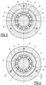
figure 3 est une vue en coupe transversale du dispositif de roulement de lafigure 2 ; - la
figure 4 est une vue en coupe transversale du dispositif de roulement de lafigure 3 en position de démontage ; et - la
figure 5 est une vue en coupe longitudinale détaillée d'un flasque d'extrémité et d'un dispositif de roulement d'une variante du moteur selon l'invention.
- the
figure 1 is a schematic representation in longitudinal section of an electric motor; - the
figure 2 is a detailed longitudinal sectional view of an end flange and a motor rolling device of thefigure 1 ; - the
figure 3 is a cross-sectional view of the rolling device of thefigure 2 ; - the
figure 4 is a cross-sectional view of the rolling device of thefigure 3 in disassembly position; and - the
figure 5 is a detailed longitudinal sectional view of an end flange and a rolling device of a variant of the engine according to the invention.
Un moteur 10 représenté sur la
Comme représenté
L'arbre 16 portant le rotor 12 est sensiblement cylindrique, s'étendant le long d'un axe longitudinal A-A', et libre en rotation par rapport au carter 20, autour de l'axe A-A' grâce à l'action du ou des paliers à roulement 24.The
Le palier à roulement 24 comprend une bague interne 26 et une bague externe 28 enserrant une pluralité d'éléments roulants 30.The rolling
Comme représenté
Le boitier 23 est maintenu fixé au flasque 22, en appui sur un épaulement 34 du boitier 23, par exemple au moyen de vis passant à travers des orifices 36 percés dans l'épaulement 34, et engagées dans des filetages 38 du flasque d'extrémité 22.The
Comme représenté
De même le flasque 22 présente au moins une cavité 42, par exemple des secteurs en retrait, sur une partie de la surface de contact circonférentielle avec le boitier 23. Par secteur en retrait, on entend cette fois-ci que la distance entre la paroi de la cavité 42 et l'axe A-A' est plus importante que la distance entre l'axe A-A' et la paroi circonférentielle du reste du flasque 22.Similarly, the
Le boitier 23 présente en outre au moins une portée de centrage 44 sur le reste de la surface de contact circonférentielle avec le flasque 22, et le flasque 22 présente de même au moins une portée de centrage 46 sur le reste de la surface de contact circonférentielle avec le boitier 23. La distance entre l'axe A-A' et la portée de centrage 44 du boitier 23 est sensiblement égale à la distance entre l'axe A-A' et la portée de centrage 46 du flasque 22. Cette distance entre l'axe A-A' et les portées de centrage 44, 46 est supérieure à la distance entre l'axe A-A' et la paroi de la cavité 40 du boitier 23, et inférieure à la distance entre l'axe A-A' et la paroi de la cavité 42 du flasque 22.The
Avantageusement, le boitier 23 et le flasque 22 présentent plusieurs secteurs en retrait 40, 42 et plusieurs portées de centrage 44, 46, repartis régulièrement autour de l'axe A-A'. Par exemple, le boitier 23 et le flasque 22 présentent le même nombre de secteurs en retrait 40, 42 et de portées de centrage 44, 46, alternativement réparties sur leur circonférence respectives. Chacun des secteurs en retrait 40, 42 et des portées de centrage sont séparés d'un même angle mesuré autour de l'axe A-A'.Advantageously, the
Dans l'exemple représenté, le boitier 23 et le flasque 22 présentent chacun trois secteurs en retrait 40, 42, et trois portées de centrage 44, 46, s'étendant chacun sur un secteur angulaire de 60° mesuré par rapport à l'axe A-A', répartis en alternance tous les 60° autour de l'axe A-A'.In the example shown, the
Le boitier 23 peut être déplacé entre une configuration de montage, représentée sur les
Dans la configuration de montage, les secteurs en retrait 40 du boitier 23 sont disposés en regard des secteurs en retrait 42 du flasque 22, et coopèrent pour former des conduits 48. Les portées de centrage 44 du boitier 23 sont alors disposées en appui contre les portées de centrage 46 du flasque 22. Le centrage de l'axe 16 et la fixation du boitier 23 au carter 20 sont alors assurés par la coopération des portées de centrage 44, 46, permettant au moteur électrique 10 de fonctionner de manière optimale. En effet, la rotation de l'arbre 16 par rapport au carter 20 est alors permise par la rotation de la bague interne 26 du palier de roulement 24 dans la bague externe 28 grâce aux éléments de roulement 30.In the mounting configuration, the recessed
Le boitier 23 peut être passé en configuration de démontage par une rotation de 60° autour de l'axe A-A' en partant de la configuration de montage.The
Dans la configuration de démontage, les portées de centrage 44 du boitier 23 sont en regard des secteurs en retrait 42 du flasque 22, et les portées de centrage 46 du flasque 22 sont en regard des secteurs en retrait 40 du boitier 23. Le boitier 23 et le flasque 22 présentent alors un jeu entre eux dont la largeur est notée j. Le jeu entre le boitier 23 et le flasque 22 est suffisant pour déplacer axialement le boitier 23 le long de l'arbre 16, jusqu'à l'extrémité libre de l'arbre 16, pour démonter le palier à roulement 24 dans un but d'entretien ou de remplacement.In the disassembly configuration, the centering bearing surfaces 44 of the
Le boitier 23 contient, en plus du palier à roulement 24, un déflecteur fixe 50, qui vient en appui axialement contre la bague extérieure 28 du roulement. Le déflecteur fixe 50 est positionné entre le boîtier 23 et une entretoise tournante 52 associée à l'arbre 16 et entourant l'arbre 16.The
L'étanchéité du carter 20 est en outre renforcée par un déflecteur interne 54 et un déflecteur externe 56, tous deux enserrés autour de l'arbre 16. Le boitier 23 présente sur une face interne des rainures internes 57 qui s'étendent circonférentiellement autour de l'axe A-A'. Le déflecteur interne 54 présente des nervures parallèles aux rainures 57, qui pénètrent dans les rainures 57 pour former un ensemble de chicanes d'étanchéité internes 58.Le boitier 23 est fermé par un couvercle 60 qui présente des rainures externes 61 qui s'étendent circonférentiellement autour de l'axe A-A'. Le déflecteur externe 56 présente des nervures parallèles aux rainures 61, qui pénètrent dans les rainures 61 pour former un ensemble de chicanes d'étanchéité externe 62 comme représenté
Le carter 20 comporte avantageusement une bague de pré-centrage 64, fixée ou intégrée au flasque 22. Cette bague de pré-centrage 64 est configurée pour porter l'arbre 16 en appui sur le déflecteur interne 54, en position de démontage lorsque le boitier de roulement 23 est retiré. Avantageusement, la bague de pré-centrage 64 présente un épaulement 66 permettant de la centrer dans le flasque 22. En variante, la bague 64 peut porter directement l'arbre 16 en position de démontage lorsque le boîtier 23 est retiré.The
Selon une variante correspondant notamment au cas où le moteur est un moteur asynchrone, le carter 10 est dépourvu de bague de pré-centrage 64. Le stator 14 présente un alésage configuré pour porter directement l'arbre 16 en position de démontage lorsque le boîtier 23 est retiré. Dans cette variante, le jeu j entre le boitier 23 et le flasque 22 est supérieur à l'entrefer e séparant le stator 14 du rotor 12. Ainsi, en position de démontage, le rotor 12 vient en appui sur l'alésage du stator 14, et le jeu entre le boitier 23 et le flasque 22 est suffisant pour procéder au retrait du boitier 23.According to a variant corresponding in particular to the case where the motor is an asynchronous motor, the
Selon une autre variante représentée sur la
Le procédé de démontage du palier de roulement 24 se déroule selon les étapes suivantes :
- démontage et retrait du couvercle 60 et désengagement des rainures externes 61 des nervures du déflecteur externe 56 ;
- démontage et retrait du déflecteur externe 56, de l'entretoise 52 et du déflecteur fixe 50 ;
- retrait des vis de fixation du boitier 23 des filetages 38 du flasque 22 ;- rotation du boitier 23 d'un angle de 60° par
rapport au flasque 22, par exemple au moyen d'un outil inséré dans les orifices 36 ; - retrait du boitier 23 le long de l'arbre 16, et désengagement des rainures internes 57 des nervures du déflecteur
interne 54 ; et - extraction du palier de roulement 24 hors du
boitier 23.
- disassembling and removing the
cover 60 and disengaging theouter grooves 61 from the ribs of theouter baffle 56; - disassembly and removal of the
outer baffle 56, thespacer 52 and the fixedbaffle 50; - removal of the fastening screws of the
housing 23 of thethreads 38 of theflange 22. - rotation of thehousing 23 by an angle of 60 ° relative to theflange 22, for example by means of a tool inserted into theorifices 36; - removing the
housing 23 along theshaft 16, and disengaging theinternal grooves 57 from the ribs of theinner baffle 54; and - extraction of the rolling
bearing 24 out of thehousing 23.
Lors du remontage, aucun effort axial ni radial n'est appliqué entre le boîtier 23 et le flasque 22. Ceci permet d'éviter tout risque de dégradation du roulement 24 lors du remontage.During reassembly, no axial or radial force is applied between the
L'invention décrite permet la fourniture d'un moteur électrique dont les roulements sont facilement démontables pour l'entretien ou le remplacement. Le démontage ne nécessite notamment pas de retrait de l'arbre et de dépose du rotor, qui est une étape complexe nécessitant un personnel qualifiés et des moyens de sécurité important. Le moteur selon l'invention permet ainsi de réaliser des économies de personnel et de matériel notables.The invention described allows the provision of an electric motor whose bearings are easily removable for maintenance or replacement. Disassembly does not require in particular removal of the shaft and removal of the rotor, which is a complex step requiring qualified personnel and important security means. The engine according to the invention thus makes it possible to save significant personnel and equipment.
Claims (10)
Applications Claiming Priority (1)
| Application Number | Priority Date | Filing Date | Title |
|---|---|---|---|
| FR1652346A FR3049126B1 (en) | 2016-03-18 | 2016-03-18 | REMOVABLE ELECTRIC MOTOR |
Publications (2)
| Publication Number | Publication Date |
|---|---|
| EP3220515A1 true EP3220515A1 (en) | 2017-09-20 |
| EP3220515B1 EP3220515B1 (en) | 2020-11-25 |
Family
ID=56119544
Family Applications (1)
| Application Number | Title | Priority Date | Filing Date |
|---|---|---|---|
| EP17161871.3A Active EP3220515B1 (en) | 2016-03-18 | 2017-03-20 | Demountable electric motor |
Country Status (5)
| Country | Link |
|---|---|
| EP (1) | EP3220515B1 (en) |
| JP (1) | JP7195723B2 (en) |
| CN (1) | CN107404177B (en) |
| ES (1) | ES2854753T3 (en) |
| FR (1) | FR3049126B1 (en) |
Cited By (1)
| Publication number | Priority date | Publication date | Assignee | Title |
|---|---|---|---|---|
| CN115632523A (en) * | 2022-09-07 | 2023-01-20 | 扬州市华胜机电科技有限公司 | Motor convenient to shell dismouting |
Families Citing this family (2)
| Publication number | Priority date | Publication date | Assignee | Title |
|---|---|---|---|---|
| JP7302235B2 (en) * | 2019-03-29 | 2023-07-04 | 株式会社デンソー | Rotating electric machine |
| JP7252056B2 (en) * | 2019-05-21 | 2023-04-04 | 株式会社日立産機システム | Linear motor, linear compressor using this linear motor, and air suspension using linear compressor |
Citations (4)
| Publication number | Priority date | Publication date | Assignee | Title |
|---|---|---|---|---|
| EP1460747A1 (en) * | 2003-03-19 | 2004-09-22 | Minebea Co., Ltd. | Bearing holder and casing of a electric motor |
| US20120062076A1 (en) * | 2010-09-09 | 2012-03-15 | Takashi Nagayama | Motor |
| US20150123517A1 (en) * | 2012-05-29 | 2015-05-07 | Mitsubishi Electric Corporation | Rotary electric machine and bearing changing method |
| FR3024611A1 (en) * | 2014-08-01 | 2016-02-05 | Alstom Transp Tech | ELECTRIC MOTOR AND DISASSEMBLY METHOD |
Family Cites Families (2)
| Publication number | Priority date | Publication date | Assignee | Title |
|---|---|---|---|---|
| DE102005030217A1 (en) * | 2005-06-29 | 2007-01-04 | Robert Bosch Gmbh | Electric motor and gear drive unit for actuators in the motor vehicle |
| JP5958048B2 (en) * | 2012-04-26 | 2016-07-27 | 富士電機株式会社 | Bearing support structure for rotating electrical machines |
-
2016
- 2016-03-18 FR FR1652346A patent/FR3049126B1/en not_active Expired - Fee Related
-
2017
- 2017-03-17 CN CN201710161838.2A patent/CN107404177B/en active Active
- 2017-03-17 JP JP2017052485A patent/JP7195723B2/en active Active
- 2017-03-20 ES ES17161871T patent/ES2854753T3/en active Active
- 2017-03-20 EP EP17161871.3A patent/EP3220515B1/en active Active
Patent Citations (4)
| Publication number | Priority date | Publication date | Assignee | Title |
|---|---|---|---|---|
| EP1460747A1 (en) * | 2003-03-19 | 2004-09-22 | Minebea Co., Ltd. | Bearing holder and casing of a electric motor |
| US20120062076A1 (en) * | 2010-09-09 | 2012-03-15 | Takashi Nagayama | Motor |
| US20150123517A1 (en) * | 2012-05-29 | 2015-05-07 | Mitsubishi Electric Corporation | Rotary electric machine and bearing changing method |
| FR3024611A1 (en) * | 2014-08-01 | 2016-02-05 | Alstom Transp Tech | ELECTRIC MOTOR AND DISASSEMBLY METHOD |
Cited By (2)
| Publication number | Priority date | Publication date | Assignee | Title |
|---|---|---|---|---|
| CN115632523A (en) * | 2022-09-07 | 2023-01-20 | 扬州市华胜机电科技有限公司 | Motor convenient to shell dismouting |
| CN115632523B (en) * | 2022-09-07 | 2023-10-20 | 扬州市华胜机电科技有限公司 | Motor convenient to shell dismouting |
Also Published As
| Publication number | Publication date |
|---|---|
| CN107404177B (en) | 2021-01-05 |
| ES2854753T3 (en) | 2021-09-22 |
| FR3049126B1 (en) | 2020-12-04 |
| JP7195723B2 (en) | 2022-12-26 |
| JP2017175905A (en) | 2017-09-28 |
| FR3049126A1 (en) | 2017-09-22 |
| CN107404177A (en) | 2017-11-28 |
| EP3220515B1 (en) | 2020-11-25 |
Similar Documents
| Publication | Publication Date | Title |
|---|---|---|
| EP3220515B1 (en) | Demountable electric motor | |
| FR3087226A1 (en) | AIRCRAFT TURBOMACHINE WITH MECHANICAL REDUCER AND CONTRAROTATIVE TURBINE | |
| FR2933544A1 (en) | Machine e.g. alternating current asynchronous electrical motor, for rail transit car, has fixed rim fixed to carcass outside extension of exterior space of bearings, and rotating rim fixed to shaft remote from internal ring of bearings | |
| EP3007331A1 (en) | Electric motor and disassembling method | |
| FR3057029A1 (en) | TURBOPROPULSEUR COMPRISING AN INTEGRATED ELECTRICITY GENERATOR | |
| FR2851377A1 (en) | DYNAMOELECTRIC MACHINE | |
| EP3601747B1 (en) | Accessory gearbox for a gas turbine engine | |
| EP2186705B1 (en) | Instrumented roller bearing assembly for railway axle and corresponding method of assembling | |
| EP3735379B1 (en) | Turboprop with an integrated electric generator | |
| EP2723995B1 (en) | Accessory relay having an extended service life | |
| EP3645903B1 (en) | Motor vehicle rotary electric machine drive assembly | |
| EP1981151A1 (en) | Rotating machine having an explosion-proof cover | |
| EP4069945B1 (en) | Rigid bar for electrically connecting a machine in an aircraft turbine engine | |
| EP3926793A1 (en) | Electrical equipment with improved thermal tolerance, and associated vehicle | |
| EP3990792B1 (en) | Rotating electrical machine equipped with a rolling bearing pretensioning member | |
| EP3819148A1 (en) | Device for cooling an electric traction motor of a vehicle, associated motor assembly, vehicle and replacement method | |
| FR3084977A1 (en) | ELECTRIC MOTOR FOR AN AIRCRAFT | |
| WO2016207544A1 (en) | Bearing support | |
| EP2060747B1 (en) | Attachment of a bearing supporting a rotor on a turbomachine | |
| WO2017134376A1 (en) | Pulley assembly for a rotating electrical machine | |
| EP3817201A1 (en) | Electric traction motor of a vehicle | |
| EP4020772A1 (en) | Electric motor and vehicle provided with such a motor | |
| FR3087224A1 (en) | SYSTEM FOR FIXING A SHAFT OF A CONTRAROTATIVE TURBINE FOR AN AIRCRAFT TURBOMACHINE | |
| FR3124036A1 (en) | MULTIPLE AXIAL FLOW ELECTRIC ROTATING MACHINE WITH A HOLLOW CONFIGURATION | |
| FR3124542A1 (en) | AIRCRAFT TURBOMACHINE EQUIPPED WITH AN ELECTRIC MACHINE |
Legal Events
| Date | Code | Title | Description |
|---|---|---|---|
| PUAI | Public reference made under article 153(3) epc to a published international application that has entered the european phase |
Free format text: ORIGINAL CODE: 0009012 |
|
| STAA | Information on the status of an ep patent application or granted ep patent |
Free format text: STATUS: THE APPLICATION HAS BEEN PUBLISHED |
|
| STAA | Information on the status of an ep patent application or granted ep patent |
Free format text: STATUS: REQUEST FOR EXAMINATION WAS MADE |
|
| AK | Designated contracting states |
Kind code of ref document: A1 Designated state(s): AL AT BE BG CH CY CZ DE DK EE ES FI FR GB GR HR HU IE IS IT LI LT LU LV MC MK MT NL NO PL PT RO RS SE SI SK SM TR |
|
| AX | Request for extension of the european patent |
Extension state: BA ME |
|
| 17P | Request for examination filed |
Effective date: 20170829 |
|
| RBV | Designated contracting states (corrected) |
Designated state(s): AL AT BE BG CH CY CZ DE DK EE ES FI FR GB GR HR HU IE IS IT LI LT LU LV MC MK MT NL NO PL PT RO RS SE SI SK SM TR |
|
| STAA | Information on the status of an ep patent application or granted ep patent |
Free format text: STATUS: EXAMINATION IS IN PROGRESS |
|
| 17Q | First examination report despatched |
Effective date: 20180911 |
|
| GRAP | Despatch of communication of intention to grant a patent |
Free format text: ORIGINAL CODE: EPIDOSNIGR1 |
|
| STAA | Information on the status of an ep patent application or granted ep patent |
Free format text: STATUS: GRANT OF PATENT IS INTENDED |
|
| INTG | Intention to grant announced |
Effective date: 20200108 |
|
| GRAJ | Information related to disapproval of communication of intention to grant by the applicant or resumption of examination proceedings by the epo deleted |
Free format text: ORIGINAL CODE: EPIDOSDIGR1 |
|
| STAA | Information on the status of an ep patent application or granted ep patent |
Free format text: STATUS: EXAMINATION IS IN PROGRESS |
|
| INTC | Intention to grant announced (deleted) | ||
| GRAP | Despatch of communication of intention to grant a patent |
Free format text: ORIGINAL CODE: EPIDOSNIGR1 |
|
| STAA | Information on the status of an ep patent application or granted ep patent |
Free format text: STATUS: GRANT OF PATENT IS INTENDED |
|
| INTG | Intention to grant announced |
Effective date: 20200708 |
|
| GRAS | Grant fee paid |
Free format text: ORIGINAL CODE: EPIDOSNIGR3 |
|
| GRAA | (expected) grant |
Free format text: ORIGINAL CODE: 0009210 |
|
| STAA | Information on the status of an ep patent application or granted ep patent |
Free format text: STATUS: THE PATENT HAS BEEN GRANTED |
|
| AK | Designated contracting states |
Kind code of ref document: B1 Designated state(s): AL AT BE BG CH CY CZ DE DK EE ES FI FR GB GR HR HU IE IS IT LI LT LU LV MC MK MT NL NO PL PT RO RS SE SI SK SM TR |
|
| REG | Reference to a national code |
Ref country code: GB Ref legal event code: FG4D Free format text: NOT ENGLISH |
|
| REG | Reference to a national code |
Ref country code: CH Ref legal event code: EP |
|
| REG | Reference to a national code |
Ref country code: AT Ref legal event code: REF Ref document number: 1339413 Country of ref document: AT Kind code of ref document: T Effective date: 20201215 |
|
| REG | Reference to a national code |
Ref country code: DE Ref legal event code: R096 Ref document number: 602017028066 Country of ref document: DE |
|
| REG | Reference to a national code |
Ref country code: IE Ref legal event code: FG4D Free format text: LANGUAGE OF EP DOCUMENT: FRENCH |
|
| REG | Reference to a national code |
Ref country code: CH Ref legal event code: NV Representative=s name: NOVAGRAAF INTERNATIONAL SA, CH |
|
| REG | Reference to a national code |
Ref country code: SE Ref legal event code: TRGR |
|
| REG | Reference to a national code |
Ref country code: DE Ref legal event code: R082 Ref document number: 602017028066 Country of ref document: DE Representative=s name: WR SERVICES GMBH, DE |
|
| REG | Reference to a national code |
Ref country code: NL Ref legal event code: FP |
|
| PG25 | Lapsed in a contracting state [announced via postgrant information from national office to epo] |
Ref country code: FI Free format text: LAPSE BECAUSE OF FAILURE TO SUBMIT A TRANSLATION OF THE DESCRIPTION OR TO PAY THE FEE WITHIN THE PRESCRIBED TIME-LIMIT Effective date: 20201125 Ref country code: GR Free format text: LAPSE BECAUSE OF FAILURE TO SUBMIT A TRANSLATION OF THE DESCRIPTION OR TO PAY THE FEE WITHIN THE PRESCRIBED TIME-LIMIT Effective date: 20210226 Ref country code: PT Free format text: LAPSE BECAUSE OF FAILURE TO SUBMIT A TRANSLATION OF THE DESCRIPTION OR TO PAY THE FEE WITHIN THE PRESCRIBED TIME-LIMIT Effective date: 20210325 Ref country code: RS Free format text: LAPSE BECAUSE OF FAILURE TO SUBMIT A TRANSLATION OF THE DESCRIPTION OR TO PAY THE FEE WITHIN THE PRESCRIBED TIME-LIMIT Effective date: 20201125 Ref country code: NO Free format text: LAPSE BECAUSE OF FAILURE TO SUBMIT A TRANSLATION OF THE DESCRIPTION OR TO PAY THE FEE WITHIN THE PRESCRIBED TIME-LIMIT Effective date: 20210225 |
|
| PG25 | Lapsed in a contracting state [announced via postgrant information from national office to epo] |
Ref country code: BG Free format text: LAPSE BECAUSE OF FAILURE TO SUBMIT A TRANSLATION OF THE DESCRIPTION OR TO PAY THE FEE WITHIN THE PRESCRIBED TIME-LIMIT Effective date: 20210225 Ref country code: PL Free format text: LAPSE BECAUSE OF FAILURE TO SUBMIT A TRANSLATION OF THE DESCRIPTION OR TO PAY THE FEE WITHIN THE PRESCRIBED TIME-LIMIT Effective date: 20201125 Ref country code: LV Free format text: LAPSE BECAUSE OF FAILURE TO SUBMIT A TRANSLATION OF THE DESCRIPTION OR TO PAY THE FEE WITHIN THE PRESCRIBED TIME-LIMIT Effective date: 20201125 Ref country code: IS Free format text: LAPSE BECAUSE OF FAILURE TO SUBMIT A TRANSLATION OF THE DESCRIPTION OR TO PAY THE FEE WITHIN THE PRESCRIBED TIME-LIMIT Effective date: 20210325 |
|
| REG | Reference to a national code |
Ref country code: LT Ref legal event code: MG9D |
|
| PG25 | Lapsed in a contracting state [announced via postgrant information from national office to epo] |
Ref country code: HR Free format text: LAPSE BECAUSE OF FAILURE TO SUBMIT A TRANSLATION OF THE DESCRIPTION OR TO PAY THE FEE WITHIN THE PRESCRIBED TIME-LIMIT Effective date: 20201125 |
|
| PG25 | Lapsed in a contracting state [announced via postgrant information from national office to epo] |
Ref country code: SK Free format text: LAPSE BECAUSE OF FAILURE TO SUBMIT A TRANSLATION OF THE DESCRIPTION OR TO PAY THE FEE WITHIN THE PRESCRIBED TIME-LIMIT Effective date: 20201125 Ref country code: RO Free format text: LAPSE BECAUSE OF FAILURE TO SUBMIT A TRANSLATION OF THE DESCRIPTION OR TO PAY THE FEE WITHIN THE PRESCRIBED TIME-LIMIT Effective date: 20201125 Ref country code: SM Free format text: LAPSE BECAUSE OF FAILURE TO SUBMIT A TRANSLATION OF THE DESCRIPTION OR TO PAY THE FEE WITHIN THE PRESCRIBED TIME-LIMIT Effective date: 20201125 Ref country code: LT Free format text: LAPSE BECAUSE OF FAILURE TO SUBMIT A TRANSLATION OF THE DESCRIPTION OR TO PAY THE FEE WITHIN THE PRESCRIBED TIME-LIMIT Effective date: 20201125 Ref country code: EE Free format text: LAPSE BECAUSE OF FAILURE TO SUBMIT A TRANSLATION OF THE DESCRIPTION OR TO PAY THE FEE WITHIN THE PRESCRIBED TIME-LIMIT Effective date: 20201125 |
|
| REG | Reference to a national code |
Ref country code: DE Ref legal event code: R097 Ref document number: 602017028066 Country of ref document: DE |
|
| PG25 | Lapsed in a contracting state [announced via postgrant information from national office to epo] |
Ref country code: DK Free format text: LAPSE BECAUSE OF FAILURE TO SUBMIT A TRANSLATION OF THE DESCRIPTION OR TO PAY THE FEE WITHIN THE PRESCRIBED TIME-LIMIT Effective date: 20201125 |
|
| REG | Reference to a national code |
Ref country code: ES Ref legal event code: FG2A Ref document number: 2854753 Country of ref document: ES Kind code of ref document: T3 Effective date: 20210922 |
|
| PLBE | No opposition filed within time limit |
Free format text: ORIGINAL CODE: 0009261 |
|
| STAA | Information on the status of an ep patent application or granted ep patent |
Free format text: STATUS: NO OPPOSITION FILED WITHIN TIME LIMIT |
|
| PG25 | Lapsed in a contracting state [announced via postgrant information from national office to epo] |
Ref country code: AL Free format text: LAPSE BECAUSE OF FAILURE TO SUBMIT A TRANSLATION OF THE DESCRIPTION OR TO PAY THE FEE WITHIN THE PRESCRIBED TIME-LIMIT Effective date: 20201125 Ref country code: MC Free format text: LAPSE BECAUSE OF FAILURE TO SUBMIT A TRANSLATION OF THE DESCRIPTION OR TO PAY THE FEE WITHIN THE PRESCRIBED TIME-LIMIT Effective date: 20201125 |
|
| 26N | No opposition filed |
Effective date: 20210826 |
|
| GBPC | Gb: european patent ceased through non-payment of renewal fee |
Effective date: 20210320 |
|
| PG25 | Lapsed in a contracting state [announced via postgrant information from national office to epo] |
Ref country code: SI Free format text: LAPSE BECAUSE OF FAILURE TO SUBMIT A TRANSLATION OF THE DESCRIPTION OR TO PAY THE FEE WITHIN THE PRESCRIBED TIME-LIMIT Effective date: 20201125 |
|
| REG | Reference to a national code |
Ref country code: BE Ref legal event code: MM Effective date: 20210331 |
|
| PG25 | Lapsed in a contracting state [announced via postgrant information from national office to epo] |
Ref country code: LU Free format text: LAPSE BECAUSE OF NON-PAYMENT OF DUE FEES Effective date: 20210320 Ref country code: GB Free format text: LAPSE BECAUSE OF NON-PAYMENT OF DUE FEES Effective date: 20210320 Ref country code: IE Free format text: LAPSE BECAUSE OF NON-PAYMENT OF DUE FEES Effective date: 20210320 |
|
| PG25 | Lapsed in a contracting state [announced via postgrant information from national office to epo] |
Ref country code: IS Free format text: LAPSE BECAUSE OF FAILURE TO SUBMIT A TRANSLATION OF THE DESCRIPTION OR TO PAY THE FEE WITHIN THE PRESCRIBED TIME-LIMIT Effective date: 20210325 |
|
| PG25 | Lapsed in a contracting state [announced via postgrant information from national office to epo] |
Ref country code: BE Free format text: LAPSE BECAUSE OF NON-PAYMENT OF DUE FEES Effective date: 20210331 |
|
| REG | Reference to a national code |
Ref country code: AT Ref legal event code: UEP Ref document number: 1339413 Country of ref document: AT Kind code of ref document: T Effective date: 20201125 |
|
| PGFP | Annual fee paid to national office [announced via postgrant information from national office to epo] |
Ref country code: FR Payment date: 20230324 Year of fee payment: 7 Ref country code: CZ Payment date: 20230313 Year of fee payment: 7 Ref country code: AT Payment date: 20230322 Year of fee payment: 7 |
|
| PG25 | Lapsed in a contracting state [announced via postgrant information from national office to epo] |
Ref country code: HU Free format text: LAPSE BECAUSE OF FAILURE TO SUBMIT A TRANSLATION OF THE DESCRIPTION OR TO PAY THE FEE WITHIN THE PRESCRIBED TIME-LIMIT; INVALID AB INITIO Effective date: 20170320 |
|
| PGFP | Annual fee paid to national office [announced via postgrant information from national office to epo] |
Ref country code: SE Payment date: 20230314 Year of fee payment: 7 Ref country code: IT Payment date: 20230328 Year of fee payment: 7 Ref country code: DE Payment date: 20230321 Year of fee payment: 7 |
|
| PG25 | Lapsed in a contracting state [announced via postgrant information from national office to epo] |
Ref country code: CY Free format text: LAPSE BECAUSE OF FAILURE TO SUBMIT A TRANSLATION OF THE DESCRIPTION OR TO PAY THE FEE WITHIN THE PRESCRIBED TIME-LIMIT Effective date: 20201125 |
|
| PGFP | Annual fee paid to national office [announced via postgrant information from national office to epo] |
Ref country code: NL Payment date: 20230321 Year of fee payment: 7 |
|
| PGFP | Annual fee paid to national office [announced via postgrant information from national office to epo] |
Ref country code: ES Payment date: 20230529 Year of fee payment: 7 Ref country code: CH Payment date: 20230401 Year of fee payment: 7 |
|
| P01 | Opt-out of the competence of the unified patent court (upc) registered |
Effective date: 20230823 |
|
| PGFP | Annual fee paid to national office [announced via postgrant information from national office to epo] |
Ref country code: NL Payment date: 20240320 Year of fee payment: 8 |