EP3990792B1 - Rotating electrical machine equipped with a rolling bearing pretensioning member - Google Patents
Rotating electrical machine equipped with a rolling bearing pretensioning member Download PDFInfo
- Publication number
- EP3990792B1 EP3990792B1 EP20733645.4A EP20733645A EP3990792B1 EP 3990792 B1 EP3990792 B1 EP 3990792B1 EP 20733645 A EP20733645 A EP 20733645A EP 3990792 B1 EP3990792 B1 EP 3990792B1
- Authority
- EP
- European Patent Office
- Prior art keywords
- bearing
- rolling bearing
- recess
- holding
- holding member
- Prior art date
- Legal status (The legal status is an assumption and is not a legal conclusion. Google has not performed a legal analysis and makes no representation as to the accuracy of the status listed.)
- Active
Links
- 238000005096 rolling process Methods 0.000 title claims 13
- 239000000463 material Substances 0.000 claims description 7
- 238000004804 winding Methods 0.000 description 10
- 230000004323 axial length Effects 0.000 description 2
- 238000001816 cooling Methods 0.000 description 2
- 210000003298 dental enamel Anatomy 0.000 description 2
- 230000033001 locomotion Effects 0.000 description 2
- 229910052782 aluminium Inorganic materials 0.000 description 1
- XAGFODPZIPBFFR-UHFFFAOYSA-N aluminium Chemical compound [Al] XAGFODPZIPBFFR-UHFFFAOYSA-N 0.000 description 1
- 230000005540 biological transmission Effects 0.000 description 1
- 238000003475 lamination Methods 0.000 description 1
- 229910052751 metal Inorganic materials 0.000 description 1
- 239000002184 metal Substances 0.000 description 1
- 230000002441 reversible effect Effects 0.000 description 1
- 229910000859 α-Fe Inorganic materials 0.000 description 1
Images


Classifications
-
- F—MECHANICAL ENGINEERING; LIGHTING; HEATING; WEAPONS; BLASTING
- F16—ENGINEERING ELEMENTS AND UNITS; GENERAL MEASURES FOR PRODUCING AND MAINTAINING EFFECTIVE FUNCTIONING OF MACHINES OR INSTALLATIONS; THERMAL INSULATION IN GENERAL
- F16C—SHAFTS; FLEXIBLE SHAFTS; ELEMENTS OR CRANKSHAFT MECHANISMS; ROTARY BODIES OTHER THAN GEARING ELEMENTS; BEARINGS
- F16C25/00—Bearings for exclusively rotary movement adjustable for wear or play
- F16C25/06—Ball or roller bearings
- F16C25/08—Ball or roller bearings self-adjusting
- F16C25/083—Ball or roller bearings self-adjusting with resilient means acting axially on a race ring to preload the bearing
-
- F—MECHANICAL ENGINEERING; LIGHTING; HEATING; WEAPONS; BLASTING
- F16—ENGINEERING ELEMENTS AND UNITS; GENERAL MEASURES FOR PRODUCING AND MAINTAINING EFFECTIVE FUNCTIONING OF MACHINES OR INSTALLATIONS; THERMAL INSULATION IN GENERAL
- F16C—SHAFTS; FLEXIBLE SHAFTS; ELEMENTS OR CRANKSHAFT MECHANISMS; ROTARY BODIES OTHER THAN GEARING ELEMENTS; BEARINGS
- F16C27/00—Elastic or yielding bearings or bearing supports, for exclusively rotary movement
- F16C27/04—Ball or roller bearings, e.g. with resilient rolling bodies
-
- F—MECHANICAL ENGINEERING; LIGHTING; HEATING; WEAPONS; BLASTING
- F16—ENGINEERING ELEMENTS AND UNITS; GENERAL MEASURES FOR PRODUCING AND MAINTAINING EFFECTIVE FUNCTIONING OF MACHINES OR INSTALLATIONS; THERMAL INSULATION IN GENERAL
- F16C—SHAFTS; FLEXIBLE SHAFTS; ELEMENTS OR CRANKSHAFT MECHANISMS; ROTARY BODIES OTHER THAN GEARING ELEMENTS; BEARINGS
- F16C35/00—Rigid support of bearing units; Housings, e.g. caps, covers
- F16C35/04—Rigid support of bearing units; Housings, e.g. caps, covers in the case of ball or roller bearings
- F16C35/06—Mounting or dismounting of ball or roller bearings; Fixing them onto shaft or in housing
- F16C35/07—Fixing them on the shaft or housing with interposition of an element
- F16C35/077—Fixing them on the shaft or housing with interposition of an element between housing and outer race ring
-
- H—ELECTRICITY
- H02—GENERATION; CONVERSION OR DISTRIBUTION OF ELECTRIC POWER
- H02K—DYNAMO-ELECTRIC MACHINES
- H02K5/00—Casings; Enclosures; Supports
- H02K5/04—Casings or enclosures characterised by the shape, form or construction thereof
- H02K5/16—Means for supporting bearings, e.g. insulating supports or means for fitting bearings in the bearing-shields
- H02K5/173—Means for supporting bearings, e.g. insulating supports or means for fitting bearings in the bearing-shields using bearings with rolling contact, e.g. ball bearings
- H02K5/1732—Means for supporting bearings, e.g. insulating supports or means for fitting bearings in the bearing-shields using bearings with rolling contact, e.g. ball bearings radially supporting the rotary shaft at both ends of the rotor
-
- F—MECHANICAL ENGINEERING; LIGHTING; HEATING; WEAPONS; BLASTING
- F16—ENGINEERING ELEMENTS AND UNITS; GENERAL MEASURES FOR PRODUCING AND MAINTAINING EFFECTIVE FUNCTIONING OF MACHINES OR INSTALLATIONS; THERMAL INSULATION IN GENERAL
- F16C—SHAFTS; FLEXIBLE SHAFTS; ELEMENTS OR CRANKSHAFT MECHANISMS; ROTARY BODIES OTHER THAN GEARING ELEMENTS; BEARINGS
- F16C2326/00—Articles relating to transporting
- F16C2326/01—Parts of vehicles in general
-
- F—MECHANICAL ENGINEERING; LIGHTING; HEATING; WEAPONS; BLASTING
- F16—ENGINEERING ELEMENTS AND UNITS; GENERAL MEASURES FOR PRODUCING AND MAINTAINING EFFECTIVE FUNCTIONING OF MACHINES OR INSTALLATIONS; THERMAL INSULATION IN GENERAL
- F16C—SHAFTS; FLEXIBLE SHAFTS; ELEMENTS OR CRANKSHAFT MECHANISMS; ROTARY BODIES OTHER THAN GEARING ELEMENTS; BEARINGS
- F16C2326/00—Articles relating to transporting
- F16C2326/20—Land vehicles
-
- F—MECHANICAL ENGINEERING; LIGHTING; HEATING; WEAPONS; BLASTING
- F16—ENGINEERING ELEMENTS AND UNITS; GENERAL MEASURES FOR PRODUCING AND MAINTAINING EFFECTIVE FUNCTIONING OF MACHINES OR INSTALLATIONS; THERMAL INSULATION IN GENERAL
- F16C—SHAFTS; FLEXIBLE SHAFTS; ELEMENTS OR CRANKSHAFT MECHANISMS; ROTARY BODIES OTHER THAN GEARING ELEMENTS; BEARINGS
- F16C2380/00—Electrical apparatus
- F16C2380/26—Dynamo-electric machines or combinations therewith, e.g. electro-motors and generators
Definitions
- the present invention relates to a rotating electrical machine provided with a bearing prestressing member.
- the invention finds a particularly advantageous, but not exclusive, application with rotating electrical machines fitted to motor vehicles.
- a rotating electrical machine comprises a stator and a rotor secured to a shaft.
- the rotor may be integral with a driving and/or driven shaft and may belong to a rotating electric machine in the form of an alternator, an electric motor, or a reversible machine that can operate in both modes.
- the rotor comprises a body formed by a stack of sheet metal sheets held in the form of a package by means of a suitable fastening system, such as rivets.
- the rotor comprises poles formed for example by permanent magnets housed in cavities made in the magnetic mass of the rotor, as described for example in the document EP0803962 .
- the poles are formed by coils wound around the arms of the rotor.
- the stator comprises a body consisting of a stack of thin laminations forming a crown, the inner face of which is provided with slots open inwards to receive a winding.
- the winding is obtained for example from a continuous wire covered with enamel or pins welded together.
- the winding may comprise polyphase windings connected in star or in triangle, the outputs of which are connected to an electronic control module comprising a power inverter which can also operate in rectifier mode.
- the stator is mounted in a casing comprising bearings configured to carry the shaft in rotation via bearings.
- a bearing of the rotating electrical machine ensuring the rotational guidance of the shaft must operate under mechanical stress.
- axial and/or radial For electrical machines constituting alternators, the mechanical stress is applied by the belt motion transmission system interposed between the pulley of the accessories front of the thermal engine and a pulley mounted on the shaft of the electrical machine.
- the invention thus makes it possible to facilitate the assembly of the electric machine by allowing manipulation of the assembly formed by "the bearing, the bearing retaining member, and the prestressing member" without risk of the prestress during handling and this while maintaining immobile the shaft with its bearing and the active parts (stator and rotor) when fitting the bearings of the rotating electrical machine.
- the bearing comprising an inner ring, an outer ring, and a seal disposed between the inner ring and the outer ring, the prestressing member is configured to apply an axial force on the outer ring of the bearing without coming into contact with the gasket. This extends the life of the bearing.
- the prestressing member is a wave washer or a conical washer.
- the retaining member is made of a material having a thermal expansion capacity greater than that of the bearing, to compensate for clearances between the bearing and the bearing likely to appear during expansion of the bearing at high temperature.
- the holding member is made of a plastic material.
- the holding member has a body of annular shape provided with an axial holding means for holding said holding member axially with respect to the housing.
- the retaining member consists of a tolerance ring.
- the holding member is circumscribed entirely inside the housing without protruding axially or radially from the side of a bottom of said housing.
- the invention also relates to a rotating electrical machine comprising an assembly as previously defined.
- FIG. 1 shows a rotating electric machine 10 comprising a polyphase stator 11 surrounding a rotor 12 mounted on a shaft 13 of axis X corresponding to the axis of the electric machine 10.
- the stator 11 surrounds the rotor 12 with the presence of an air gap between the inner periphery of stator 11 and outer periphery of rotor 12.
- the rotor 12 comprises, in a manner known per se, a body 15 in the form of a stack of sheets. Permanent magnets 16 are implanted in cavities of the body 15.
- the permanent magnets 16 may be made of rare earths or ferrite depending on the applications and the desired power of the electric machine 10.
- the stator 11 comprises a body 18 as well as a winding 19.
- the body 18 comprises a plurality of notches open axially and radially for mounting the stator winding 19.
- the winding 19 is formed by pins welded together.
- the winding could be formed from a continuous wire covered with enamel or from coils wound around the teeth of the body 18.
- the winding 19 could comprise polyphase windings connected in a star or in a triangle, the outputs of which are connected to an electronic control module comprising a power inverter which can also operate in rectifier mode.
- the electric machine 10 also comprises a front bearing 21 and a rear bearing 22 made for example of an aluminum-based material.
- the front bearing 21 and the rear bearing 22 are each provided with a housing 23 intended to receive a bearing 24, in particular a ball bearing, ensuring rotational guidance of the shaft 13.
- a bearing 24 comprises an inner ring 24.1, an outer ring 24.2, balls 24.3 allowing relative rotational movement between the two rings 24.1, 24.2, and a seal 24.4 arranged between the inner ring 24.1 and the outer ring 24.2.
- the front bearing 21 is located on the output side of the shaft 13 intended to cooperate with an external element of the electric machine 10, such as a gear of a gearbox, while the rear bearing 22 is located on the opposite side with respect to the output of the shaft 13.
- a bearing 21, 22 comprises a wall 26 of transverse orientation with respect to the axis X centrally comprising the housing 23 of a bearing 24 and from which comes an annular side wall 27 of axial orientation by relative to the X axis.
- a cooling chamber 29 is delimited by the outer periphery of the side wall 27 of the front bearing 21 and the inner periphery of the side wall 27 of the rear bearing 22.
- This cooling chamber 29 is hermetically closed at its axial ends by two seals 30
- the stator 11 is preferably shrunk mounted inside the front bearing 21 so as to establish intimate contact between the outer periphery of the stator body 11 and the inner periphery of the side wall 27 of the front bearing 21.
- a prestressing member 32 is arranged axially between the bottom of the housing 23 of the rear bearing 22 and the corresponding bearing 24 so as to apply an axial force on the bearing 24.
- a retaining member 33 of the bearing 24 is arranged radially between the bearing 24 and a side wall of the housing 23. The retaining member 33 is arranged to allow the preloading member 32 to be axially maintained in the housing 23 of the bearing rear 22 before the bearing 24 is inserted into the housing 23 during an assembly phase of the rotary electrical machine 10.
- an external diameter D1 of the prestressing member 32 is greater than an internal diameter D2 of the holding member 33 and less than or equal to an external diameter D3 of the holding member 33.
- the external diameter D3 of the holding member 33 is substantially equal to the internal diameter of the housing 23.
- the prestressing member 32 can thus rest on an axial end of the retaining member 33 when the "bearing 22, prestressing member 32, and retaining member 33" assembly is placed vertically so as to cooperate with a bearing 24 of shaft 13 on which rotor 12 is mounted.
- the prestressing member 32 is configured to apply an axial force on the outer ring 24.2 of the bearing 24 without coming into contact with the seal 24.4. This extends the life of the bearing 24.
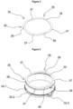
- the preloader 32 is preferably a wave washer, as shown in the figures. figure 2 , 4, and 5 .
- the washer 32 thus has a plurality of undulations 35 formed by a succession of peaks 36 and hollows 37.
- the number of undulations 35 of the washer 32 for example between 3 and 8, depends on the application and in particular of the force to be applied to bearing 24.
- washer 32 may be a conical washer.
- the retaining member 33 is arranged so as not to be in contact with the prestressing member 32 when the bearing 24 is inserted into the housing 23 of the bearing.
- the retaining member 33 has an axial length L1 less than the axial length L2 of the outer race 24.2 of the bearing 24, as shown in the picture 2 .
- the holding member 33 is made of a material, in particular a plastic material, the thermal expansion of which is greater than that of the bearing 24, to compensate for clearances between the bearing 24 and the bearing 22 likely to appear during expansion. bearing 22 at high temperature.
- the holding member 33 has a body 33.1 of annular shape provided with an axial holding means 33.2 for axially holding said holding member 33 with respect to the housing 23.
- the axial holding means 33.2 may for example be constituted by a rim intended to fit into a groove 39 of corresponding shape provided in the housing 23 (cf. figure 2 ).
- the holding member 33 may also include an anti-rotation means 33.3 consisting of a lug inserted into a recess of corresponding shape made in the housing 23.
- the presence of the anti-rotation means 33.3 is not however essential. .
- the holding member 33 is circumscribed entirely inside the housing 23 without protruding axially or radially from the side of a bottom of said housing 23.
- the holding member 33 consists of a tolerance ring.
- This tolerance ring comprises an elastically deformable annular portion to adapt to the variations in dimensions of the housing 23 during its expansion as well as a plurality of elements implanted in the internal periphery of the annular portion. These internal elements are also elastically deformable in order to guarantee contact with the bearing 24.
- the preceding description has been given by way of example only and does not limit the field of the invention, which would not be departed from by replacing the various elements by all other equivalents.
Description
La présente invention porte sur une machine électrique tournante munie d'un organe de précontrainte de roulement. L'invention trouve une application particulièrement avantageuse, mais non exclusive, avec les machines électriques tournantes équipant les véhicules automobiles.The present invention relates to a rotating electrical machine provided with a bearing prestressing member. The invention finds a particularly advantageous, but not exclusive, application with rotating electrical machines fitted to motor vehicles.
De façon connue en soi, une machine électrique tournante comporte un stator et un rotor solidaire d'un arbre. Le rotor pourra être solidaire d'un arbre menant et/ou mené et pourra appartenir à une machine électrique tournante sous la forme d'un alternateur, d'un moteur électrique, ou d'une machine réversible pouvant fonctionner dans les deux modes.In a manner known per se, a rotating electrical machine comprises a stator and a rotor secured to a shaft. The rotor may be integral with a driving and/or driven shaft and may belong to a rotating electric machine in the form of an alternator, an electric motor, or a reversible machine that can operate in both modes.
Le rotor comporte un corps formé par un empilage de feuilles de tôles maintenues sous forme de paquet au moyen d'un système de fixation adapté, tel que des rivets. Le rotor comporte des pôles formés par exemple par des aimants permanents logés dans des cavités ménagées dans la masse magnétique du rotor, comme cela est décrit par exemple dans le document
Par ailleurs, le stator comporte un corps constitué par un empilage de tôles minces formant une couronne, dont la face intérieure est pourvue d'encoches ouvertes vers l'intérieur pour recevoir un bobinage. Le bobinage est obtenu par exemple à partir d'un fil continu recouvert d'émail ou d'épingles soudées entre elles. Le bobinage pourra comporter des enroulements polyphasés connectés en étoile ou en triangle dont les sorties sont reliées à un module électronique de commande comportant un onduleur de puissance pouvant également fonctionner en mode redresseur.Furthermore, the stator comprises a body consisting of a stack of thin laminations forming a crown, the inner face of which is provided with slots open inwards to receive a winding. The winding is obtained for example from a continuous wire covered with enamel or pins welded together. The winding may comprise polyphase windings connected in star or in triangle, the outputs of which are connected to an electronic control module comprising a power inverter which can also operate in rectifier mode.
Le stator est monté dans un carter comportant des paliers configurés pour porter à rotation l'arbre par l'intermédiaire de roulements. Afin d'optimiser sa durée de vie, un roulement de la machine électrique tournante assurant le guidage en rotation de l'arbre doit fonctionner sous une contrainte mécanique axiale et/ou radiale. Pour les machines électriques constituant des alternateurs, la contrainte mécanique est appliquée par le système de transmission de mouvement à courroie interposé entre la poulie de la façade accessoires du moteur thermique et une poulie montée sur l'arbre de la machine électrique.The stator is mounted in a casing comprising bearings configured to carry the shaft in rotation via bearings. In order to optimize its service life, a bearing of the rotating electrical machine ensuring the rotational guidance of the shaft must operate under mechanical stress. axial and/or radial. For electrical machines constituting alternators, the mechanical stress is applied by the belt motion transmission system interposed between the pulley of the accessories front of the thermal engine and a pulley mounted on the shaft of the electrical machine.
Toutefois, pour certaines architectures de traction comprenant une machine électrique en prise avec un engrenage, notamment un engrenage d'une boîte de vitesses, il a été observé de nombreuses situations de vie dans lesquelles aucun couple n'est appliqué à la machine électrique tournante de sorte que le roulement n'est pas sous contrainte mécanique.However, for certain traction architectures comprising an electrical machine meshed with a gear, in particular a gear of a gearbox, many life situations have been observed in which no torque is applied to the rotating electrical machine of so that the bearing is not under mechanical stress.
La demanderesse a donc disposé un organe de précontrainte à l'intérieur d'un logement de roulement. Toutefois, cela a posé des problèmes de montage dans la mesure où il était nécessaire de déplacer l'ensemble des parties actives (rotor et stator) par rapport au palier pour faire coopérer l'arbre et un roulement correspondant d'un palier.The applicant has therefore placed a prestressing member inside a bearing housing. However, this posed assembly problems insofar as it was necessary to move all of the active parts (rotor and stator) relative to the bearing to make the shaft and a corresponding bearing of a bearing cooperate.
La présente invention vise à remédier efficacement à cet inconvénient en proposant un ensemble pour machine électrique tournante comportant :
- un palier comportant un logement pour un roulement,
- un organe de précontrainte du roulement destiné à être disposé axialement entre le fond du logement et le roulement, et
- un organe de maintien du roulement destiné à être disposé radialement entre le roulement et une paroi latérale du logement, l'organe de maintien du roulement étant agencé pour permettre de maintenir axialement l'organe de précontrainte dans le logement du palier avant que le roulement soit inséré dans le logement, pendant une phase d'assemblage de la machine électrique tournante, l'organe de maintien étant agencé de façon à ne pas être en contact avec l'organe de précontrainte lorsque le roulement est inséré dans le logement du palier.
- a bearing comprising a housing for a bearing,
- a bearing prestressing member intended to be arranged axially between the bottom of the housing and the bearing, and
- a bearing-holding member intended to be arranged radially between the bearing and a side wall of the housing, the bearing-holding member being arranged to enable the preloading member to be axially held in the housing of the bearing before the bearing is inserted into the housing, during an assembly phase of the rotary electrical machine, the holding member being arranged so as not to be in contact with the preloading member when the bearing is inserted into the housing of the bearing.
Un ensemble pour une machine électrique tournante selon le préambule de la revendication 1 est connu par le document
L'invention permet ainsi de faciliter le montage de la machine électrique en autorisant à manipuler l'ensemble formé par "le palier, l'organe de maintien du roulement, et l'organe de précontrainte" sans risque de chute de l'organe de précontrainte lors de la manipulation et cela tout en maintenant immobiles l'arbre avec son roulement et les parties actives (stator et rotor) lors de la mise en place des paliers de la machine électrique tournante.The invention thus makes it possible to facilitate the assembly of the electric machine by allowing manipulation of the assembly formed by "the bearing, the bearing retaining member, and the prestressing member" without risk of the prestress during handling and this while maintaining immobile the shaft with its bearing and the active parts (stator and rotor) when fitting the bearings of the rotating electrical machine.
Selon une réalisation, le roulement comportant une bague intérieure, une bague extérieure, et un joint disposé entre la bague intérieure et la bague extérieure, l'organe de précontrainte est configuré pour appliquer un effort axial sur la bague extérieure du roulement sans venir en contact avec le joint. Cela permet de prolonger la durée de vie du roulement.According to one embodiment, the bearing comprising an inner ring, an outer ring, and a seal disposed between the inner ring and the outer ring, the prestressing member is configured to apply an axial force on the outer ring of the bearing without coming into contact with the gasket. This extends the life of the bearing.
Selon une réalisation, l'organe de précontrainte est une rondelle ondulée ou une rondelle conique.According to one embodiment, the prestressing member is a wave washer or a conical washer.
Selon une réalisation, l'organe de maintien est réalisé dans un matériau présentant une capacité de dilatation thermique supérieure à celle du roulement, pour compenser des jeux entre le roulement et le palier susceptibles d'apparaître lors d'une dilatation du palier à haute température. Selon une réalisation, l'organe de maintien est réalisé dans un matériau plastique.According to one embodiment, the retaining member is made of a material having a thermal expansion capacity greater than that of the bearing, to compensate for clearances between the bearing and the bearing likely to appear during expansion of the bearing at high temperature. . According to one embodiment, the holding member is made of a plastic material.
Selon une réalisation, l'organe de maintien présente un corps de forme annulaire muni d'un moyen de maintien axial pour maintenir axialement ledit organe de maintien par rapport au logement.According to one embodiment, the holding member has a body of annular shape provided with an axial holding means for holding said holding member axially with respect to the housing.
Selon une réalisation, l'organe de maintien est constitué par une bague de tolérance.According to one embodiment, the retaining member consists of a tolerance ring.
Selon une réalisation, l'organe de maintien est circonscrit entièrement à l'intérieur du logement sans dépasser axialement ni radialement du côté d'un fond dudit logement.According to one embodiment, the holding member is circumscribed entirely inside the housing without protruding axially or radially from the side of a bottom of said housing.
L'invention porte également sur une machine électrique tournante comportant un ensemble tel que précédemment défini.The invention also relates to a rotating electrical machine comprising an assembly as previously defined.
L'invention sera mieux comprise à la lecture de la description qui suit et à l'examen des figures qui l'accompagnent. Ces figures ne sont données qu'à titre illustratif mais nullement limitatif de l'invention.
- La
figure 1 est une vue en coupe longitudinale d'une machine électrique tournante selon la présente invention ; - La
figure 2 est une vue en coupe détaillée du logement du roulement dans lequel sont disposés un organe de maintien du roulement et un organe de précontrainte selon la présente invention ; - La
figure 3 est une vue en perspective d'un organe de maintien du roulement destiné à être intégré dans la machine électrique tournante selon l'invention ; - La
figure 4 est une vue en perspective d'un organe de précontrainte du roulement destiné à être intégré dans la machine électrique tournante selon l'invention ; - La
figure 5 est une vue en perspective de l'organe de maintien du roulement et de l'organe de précontrainte destinés à être intégrés dans la machine électrique tournante selon l'invention.
- There
figure 1 is a longitudinal sectional view of a rotary electrical machine according to the present invention; - There
picture 2 is a detailed sectional view of the bearing housing in which are arranged a bearing retaining member and a preloading member according to the present invention; - There
picture 3 is a perspective view of a bearing retaining member intended to be integrated into the rotary electrical machine according to the invention; - There
figure 4 is a perspective view of a bearing prestressing member intended to be integrated into the rotary electrical machine according to the invention; - There
figure 5 is a perspective view of the bearing retaining member and of the preloading member intended to be integrated into the rotary electrical machine according to the invention.
Les éléments identiques, similaires, ou analogues conservent la même référence d'une figure à l'autre.Identical, similar or analogous elements retain the same reference from one figure to another.
La
Le rotor 12 comporte, de façon connue en soi, un corps 15 sous la forme d'un paquet de tôles. Des aimants permanents 16 sont implantés dans des cavités du corps 15. Les aimants permanents 16 pourront être en terres rares ou en ferrite selon les applications et la puissance recherchée de la machine électrique 10.The
Par ailleurs, le stator 11 comporte un corps 18 ainsi qu'un bobinage 19. Le corps 18 comporte une pluralité d'encoches ouvertes axialement et radialement pour le montage du bobinage statorique 19. En l'occurrence, le bobinage 19 est formé par des épingles soudées entre elles. En variante, le bobinage pourra être formé à partir d'un fil continu recouvert d'émail ou de bobines enroulées autour des dents du corps 18. Le bobinage 19 pourra comporter des enroulements polyphasés connectés en étoile ou en triangle dont les sorties sont reliées à un module électronique de commande comportant un onduleur de puissance pouvant également fonctionner en mode redresseur.Furthermore, the
La machine électrique 10 comporte également un palier avant 21 et un palier arrière 22 réalisés par exemple dans un matériau à base d'aluminium. Le palier avant 21 et le palier arrière 22 sont munis chacun d'un logement 23 destiné à recevoir un roulement 24, notamment un roulement à billes, assurant un guidage en rotation de l'arbre 13.The
Un roulement 24 comporte une bague intérieure 24.1, une bague extérieure 24.2, des billes 24.3 permettant le mouvement de rotation relatif entre les deux bagues 24.1, 24.2, et un joint 24.4 disposé entre la bague intérieure 24.1 et la bague extérieure 24.2.A
Le palier avant 21 est situé du côté de la sortie de l'arbre 13 destinée à coopérer avec un élément externe de la machine électrique 10, tel qu'un engrenage d'une boîte de vitesses, tandis que le palier arrière 22 est situé du côté opposé par rapport à la sortie de l'arbre 13.The front bearing 21 is located on the output side of the
En l'occurrence, un palier 21, 22 comporte une paroi 26 d'orientation transversale par rapport à l'axe X comprenant centralement le logement 23 d'un roulement 24 et de laquelle est issue une paroi latérale 27 annulaire d'orientation axiale par rapport à l'axe X.In this case, a
Une chambre de refroidissement 29 est délimitée par la périphérie externe de la paroi latérale 27 du palier avant 21 et la périphérie interne de la paroi latérale 27 du palier arrière 22. Cette chambre de refroidissement 29 est fermée hermétiquement à ses extrémités axiales par deux joints 30. Le stator 11 est monté de préférence fretté à l'intérieur du palier avant 21 de manière à établir un contact intime entre la périphérie externe du corps de stator 11 et la périphérie interne de la paroi latérale 27 du palier avant 21.A
Comme on peut le voir sur la
L'organe de précontrainte 32 pourra ainsi reposer sur une extrémité axiale de l'organe de maintien 33 lorsque l'ensemble "palier 22, organe de précontrainte 32, et organe de maintien 33" est placé à la verticale de façon à coopérer avec un roulement 24 de l'arbre 13 sur lequel est monté le rotor 12.The prestressing
L'organe de précontrainte 32 est configuré pour appliquer un effort axial sur la bague extérieure 24.2 du roulement 24 sans venir en contact avec le joint 24.4. Cela permet de prolonger la durée de vie du roulement 24. L'organe de précontrainte 32 est de préférence une rondelle ondulée, tel que cela est montré sur les
Selon l'invention, l'organe de maintien 33 est agencé de façon à ne pas être en contact avec l'organe de précontrainte 32 lorsque le roulement 24 est inséré dans le logement 23 du palier. A cet effet, l'organe de maintien 33 présente une longueur axiale L1 inférieure à la longueur axiale L2 de la bague extérieure 24.2 du roulement 24, tel que montré sur la
L'organe de maintien 33 est réalisé dans un matériau, notamment un matériau plastique, dont la dilatation thermique est supérieure à celle du roulement 24, pour compenser des jeux entre le roulement 24 et le palier 22 susceptibles d'apparaître lors d'une dilatation du palier 22 à haute température.The holding
En l'occurrence, comme on peut le voir sur les
L'organe de maintien 33 pourra également comporter un moyen d'anti-rotation 33.3 consistant en un ergot inséré dans une creusure de forme correspondante ménagée dans le logement 23. La présence du moyen d'anti-rotation 33.3 n'est toutefois pas indispensable.The holding
L'organe de maintien 33 est circonscrit entièrement à l'intérieur du logement 23 sans dépasser axialement ni radialement du côté d'un fond dudit logement 23.The holding
En variante, l'organe de maintien 33 est constitué par une bague de tolérance. Cette bague de tolérance comporte une portion annulaire élastiquement déformable pour s'adapter aux variations de dimensions du logement 23 lors de sa dilatation ainsi qu'une pluralité d'éléments implantés en périphérie interne de la portion annulaire. Ces éléments internes sont également élastiquement déformables afin de garantir le contact avec le roulement 24. Bien entendu, la description qui précède a été donnée à titre d'exemple uniquement et ne limite pas le domaine de l'invention dont on ne sortirait pas en remplaçant les différents éléments par tous autres équivalents.As a variant, the holding
En outre, les différentes caractéristiques, variantes, et/ou formes de réalisation de la présente invention peuvent être associées les unes avec les autres selon diverses combinaisons, dans le cadre de l'invention telle que définies par les revendications ci-jointes.Further, the various features, variations, and/or embodiments of the present invention may be associated with each other in various combinations, within the scope of the invention as defined by the appended claims.
Claims (9)
- Assembly for a rotary electric machine (10), having:- a bearing (22) having a recess (23) for a rolling bearing (24),- a member (32) for preloading the rolling bearing (24), intended to be disposed axially between the end wall of the recess (23) and the rolling bearing (24), and- a member (33) for holding the rolling bearing (24), intended to be disposed radially between the rolling bearing (24) and a lateral wall of the recess (23),the member (33) for holding the rolling bearing (24) being arranged so as to make it possible to axially hold the preloading member (32) in the recess (23) of the bearing (22) before the rolling bearing (24) is inserted into the recess (23), during a phase of assembly of the rotary electric machine (10), characterized in thatthe holding member (33) is arranged so as not to be in contact with the preloading member (32) when the rolling bearing (24) is inserted into the recess (23) of the bearing (22).
- Assembly according to Claim 1, characterized in that, the rolling bearing (24) having an inner ring (24.1), an outer ring (24.2), and a seal (24.4) disposed between the inner ring (24.1) and the outer ring (24.2), the preloading member (32) is configured to apply an axial force to the outer ring (24.2) of the rolling bearing (24) without coming into contact with the seal (24.4).
- Assembly according to either one of Claims 1 and 2, characterized in that the preloading member (32) is a wave washer or a tapered washer.
- Assembly according to any one of Claims 1 to 3, characterized in that the holding member (33) is made of a material having a thermal expansion capacity greater than that of the rolling bearing (24), so as to compensate for clearances between the rolling bearing (24) and the bearing (22) that are likely to arise during expansion of the bearing (22) at high temperature.
- Assembly according to Claim 4, characterized in that the holding member (33) is made of a plastic material.
- Assembly according to any one of Claims 1 to 5, characterized in that the holding member (33) has a body (33.1) of annular shape, provided with an axial holding means (33.2) for axially holding said holding member (33) relative to the recess (23).
- Assembly according to any one of Claims 1 to 5, characterized in that the holding member (33) consists of a tolerance ring.
- Assembly according to any one of Claims 1 to 7, characterized in that the holding member (33) is circumscribed entirely inside the recess (23) without extending axially or radially beyond the side of an end wall of said recess (23).
- Rotary electric machine (10) having an assembly as defined in any one of the preceding claims.
Applications Claiming Priority (2)
| Application Number | Priority Date | Filing Date | Title |
|---|---|---|---|
| FR1906880A FR3097912B1 (en) | 2019-06-25 | 2019-06-25 | ROTATING ELECTRIC MACHINE EQUIPPED WITH A BEARING PRE-TENSIONING BODY |
| PCT/EP2020/067561 WO2020260320A1 (en) | 2019-06-25 | 2020-06-23 | Rotating electrical machine equipped with a rolling bearing pretensioning member |
Publications (2)
| Publication Number | Publication Date |
|---|---|
| EP3990792A1 EP3990792A1 (en) | 2022-05-04 |
| EP3990792B1 true EP3990792B1 (en) | 2023-05-24 |
Family
ID=67999912
Family Applications (1)
| Application Number | Title | Priority Date | Filing Date |
|---|---|---|---|
| EP20733645.4A Active EP3990792B1 (en) | 2019-06-25 | 2020-06-23 | Rotating electrical machine equipped with a rolling bearing pretensioning member |
Country Status (7)
| Country | Link |
|---|---|
| US (1) | US20220252105A1 (en) |
| EP (1) | EP3990792B1 (en) |
| JP (1) | JP2022538108A (en) |
| KR (1) | KR20220024137A (en) |
| CN (1) | CN113939662A (en) |
| FR (1) | FR3097912B1 (en) |
| WO (1) | WO2020260320A1 (en) |
Families Citing this family (1)
| Publication number | Priority date | Publication date | Assignee | Title |
|---|---|---|---|---|
| DE102022109632A1 (en) | 2022-04-21 | 2023-10-26 | Schaeffler Technologies AG & Co. KG | Rolling bearing arrangement and electrical machine |
Family Cites Families (19)
| Publication number | Priority date | Publication date | Assignee | Title |
|---|---|---|---|---|
| DD151209A5 (en) * | 1979-06-30 | 1981-10-08 | Siemens Ag | DEVICE FOR COMPENSATING THE RADIAL GAME OF A BODY BEARING IN A BEARING BORE |
| JPS59110921A (en) * | 1982-12-13 | 1984-06-27 | Matsushita Electric Ind Co Ltd | Ball bearing device |
| JPS6055257U (en) * | 1983-09-20 | 1985-04-18 | 三洋電機株式会社 | Motor bearing structure |
| JP2924221B2 (en) * | 1991-03-05 | 1999-07-26 | 日本精工株式会社 | Resin composition for resin wound bearing |
| JPH08149741A (en) * | 1994-11-14 | 1996-06-07 | Matsushita Electric Ind Co Ltd | Bearing for motor |
| IT240620Y1 (en) | 1996-04-23 | 2001-04-02 | Bamo Elettroutensili S R L | POLAR PACK STRUCTURE, FOR DIALTERNATOR AND SIMILAR PERMANENT MAGNET ROTORS |
| JP2001304254A (en) * | 2000-04-21 | 2001-10-31 | Asmo Co Ltd | Pre-loading member for radial ball bearing |
| DE10260904A1 (en) * | 2002-12-20 | 2004-07-01 | Karl Heinz Linnig Gmbh & Co. Kg | Compressor for vehicle air conditioning system has crankshaft roller bearing held in contact with bearing race surface by spring washer |
| DE10324621A1 (en) * | 2003-05-28 | 2004-12-16 | Robert Bosch Gmbh | Electrical machine |
| DE502005003462D1 (en) * | 2005-05-11 | 2008-05-08 | Vdo Automotive Ag | A preloaded ball bearing electric machine and method of making the same |
| JP2007189793A (en) * | 2006-01-12 | 2007-07-26 | Yaskawa Electric Corp | Rotary electric machine |
| JP2008271747A (en) * | 2007-04-24 | 2008-11-06 | Asmo Co Ltd | Rotary electric machine and washer member |
| US8851227B2 (en) * | 2009-01-23 | 2014-10-07 | Aktiebolaget Skf | Bearing assembly for a power steering mechanism |
| AU2011253647B2 (en) * | 2010-11-30 | 2014-02-27 | Joy Global Surface Mining Inc | Bearing retainer assembly |
| US8840312B1 (en) * | 2013-03-13 | 2014-09-23 | Regal Beloit America, Inc. | Electric machine and associated method |
| JP2014234920A (en) * | 2013-06-05 | 2014-12-15 | 株式会社ジェイテクト | Motor |
| WO2015043629A1 (en) * | 2013-09-25 | 2015-04-02 | Aktiebolaget Skf | Rolling bearing with pre-stressing member |
| DE102016220066A1 (en) * | 2016-10-14 | 2018-04-19 | Schaeffler Technologies AG & Co. KG | Release bearing for a friction clutch |
| JP2019027523A (en) * | 2017-07-31 | 2019-02-21 | 日本電産サンキョー株式会社 | Bearing assembly and motor |
-
2019
- 2019-06-25 FR FR1906880A patent/FR3097912B1/en active Active
-
2020
- 2020-06-23 WO PCT/EP2020/067561 patent/WO2020260320A1/en unknown
- 2020-06-23 JP JP2021576508A patent/JP2022538108A/en active Pending
- 2020-06-23 EP EP20733645.4A patent/EP3990792B1/en active Active
- 2020-06-23 US US17/621,943 patent/US20220252105A1/en active Pending
- 2020-06-23 CN CN202080038855.7A patent/CN113939662A/en active Pending
- 2020-06-23 KR KR1020217041876A patent/KR20220024137A/en active Search and Examination
Also Published As
| Publication number | Publication date |
|---|---|
| FR3097912B1 (en) | 2021-06-18 |
| JP2022538108A (en) | 2022-08-31 |
| US20220252105A1 (en) | 2022-08-11 |
| WO2020260320A1 (en) | 2020-12-30 |
| FR3097912A1 (en) | 2021-01-01 |
| EP3990792A1 (en) | 2022-05-04 |
| KR20220024137A (en) | 2022-03-03 |
| CN113939662A (en) | 2022-01-14 |
Similar Documents
| Publication | Publication Date | Title |
|---|---|---|
| EP2153076B1 (en) | Indexation instrumented bearing device | |
| EP3280034B1 (en) | Rotary electric motor provided with an interconnector having supporting jacks | |
| EP3990792B1 (en) | Rotating electrical machine equipped with a rolling bearing pretensioning member | |
| EP2856613B1 (en) | Rotor of an electric machine and associated permanent magnet retaining spring | |
| FR3054745A1 (en) | ROTATING ELECTRIC MACHINE HAVING AN INTERCHARGER WITH A NUT HOOK | |
| EP3320601B1 (en) | Rotating electric machine having a centring element | |
| EP3539200A1 (en) | Rotating electrical machine comprising a speed reducer casing | |
| EP3280033A1 (en) | Rotary electric motor provided with a self-stripping interconnector | |
| EP3320602B1 (en) | Rotary electric machine provided with a reservoir of lubricant for lubricating a rolling bearing and for cooling the machine | |
| EP3320604B1 (en) | Rotary electric machine equipped with a means of adjusting the angular position of the shaft | |
| EP3850727B1 (en) | Rotating electrical machine provided with a bearing produced from two overmoulded parts | |
| EP3662565A1 (en) | Rotary electric machine equipped with a protective cover fastened by snap-fastening | |
| WO2018150128A1 (en) | Inverter for rotary electrical machine having improved cooling | |
| FR3086128A1 (en) | ROTATING ELECTRIC MACHINE WITH AT LEAST ONE LUBRICANT RESERVE THROAT | |
| FR3075501A1 (en) | ROTATING ELECTRIC MACHINE HAVING A DEVICE FOR HOLDING A SENSOR SUPPORT FOR MEASURING THE ANGULAR POSITION OF THE ROTOR | |
| FR2894007A1 (en) | Driving unit e.g. drive pulley, assembling method for e.g. alternator of motor vehicle, involves screwing pulley on shaft to transmit torque at level of front face in contact with pulley and screw between shaft and pulley | |
| FR3039938A1 (en) | ASSEMBLY FOR ROTATING ELECTRICAL MACHINE COMPRISING A FIXED COLLECTOR USING A PEN | |
| WO2018146391A1 (en) | Rotor for a rotating electrical machine provided with balancing holes | |
| WO2020245122A1 (en) | Rotating electric machine provided with a cooling chamber | |
| FR3080719A1 (en) | ROTOR OF ELECTRIC ROTATING MACHINE WITH PERMANENT SURFACE MAGNETS | |
| FR3131124A1 (en) | Stator of a rotating electrical machine equipped with an insulator of an excitation winding | |
| FR3080714A1 (en) | ROTATING ELECTRIC MACHINE STATOR WITH COIL INSULATION | |
| FR3062755A1 (en) | IMPROVED ASSEMBLY OF ROTOR OF ROTATING ELECTRICAL MACHINE | |
| FR3038792A1 (en) | ROTATING ELECTRICAL MACHINE WITH MODIFIED BEARING | |
| FR3062968A1 (en) | ROTOR OF ROTATING ELECTRIC MACHINE WITH MAGNETIC ELEMENT SUPPORT |
Legal Events
| Date | Code | Title | Description |
|---|---|---|---|
| STAA | Information on the status of an ep patent application or granted ep patent |
Free format text: STATUS: UNKNOWN |
|
| STAA | Information on the status of an ep patent application or granted ep patent |
Free format text: STATUS: THE INTERNATIONAL PUBLICATION HAS BEEN MADE |
|
| STAA | Information on the status of an ep patent application or granted ep patent |
Free format text: STATUS: THE INTERNATIONAL PUBLICATION HAS BEEN MADE |
|
| PUAI | Public reference made under article 153(3) epc to a published international application that has entered the european phase |
Free format text: ORIGINAL CODE: 0009012 |
|
| STAA | Information on the status of an ep patent application or granted ep patent |
Free format text: STATUS: REQUEST FOR EXAMINATION WAS MADE |
|
| 17P | Request for examination filed |
Effective date: 20211209 |
|
| AK | Designated contracting states |
Kind code of ref document: A1 Designated state(s): AL AT BE BG CH CY CZ DE DK EE ES FI FR GB GR HR HU IE IS IT LI LT LU LV MC MK MT NL NO PL PT RO RS SE SI SK SM TR |
|
| DAV | Request for validation of the european patent (deleted) | ||
| DAX | Request for extension of the european patent (deleted) | ||
| GRAP | Despatch of communication of intention to grant a patent |
Free format text: ORIGINAL CODE: EPIDOSNIGR1 |
|
| STAA | Information on the status of an ep patent application or granted ep patent |
Free format text: STATUS: GRANT OF PATENT IS INTENDED |
|
| INTG | Intention to grant announced |
Effective date: 20221220 |
|
| GRAS | Grant fee paid |
Free format text: ORIGINAL CODE: EPIDOSNIGR3 |
|
| GRAA | (expected) grant |
Free format text: ORIGINAL CODE: 0009210 |
|
| STAA | Information on the status of an ep patent application or granted ep patent |
Free format text: STATUS: THE PATENT HAS BEEN GRANTED |
|
| AK | Designated contracting states |
Kind code of ref document: B1 Designated state(s): AL AT BE BG CH CY CZ DE DK EE ES FI FR GB GR HR HU IE IS IT LI LT LU LV MC MK MT NL NO PL PT RO RS SE SI SK SM TR |
|
| REG | Reference to a national code |
Ref country code: GB Ref legal event code: FG4D Free format text: NOT ENGLISH |
|
| REG | Reference to a national code |
Ref country code: CH Ref legal event code: EP |
|
| REG | Reference to a national code |
Ref country code: DE Ref legal event code: R096 Ref document number: 602020011126 Country of ref document: DE |
|
| REG | Reference to a national code |
Ref country code: AT Ref legal event code: REF Ref document number: 1569651 Country of ref document: AT Kind code of ref document: T Effective date: 20230615 |
|
| REG | Reference to a national code |
Ref country code: IE Ref legal event code: FG4D Free format text: LANGUAGE OF EP DOCUMENT: FRENCH |
|
| P01 | Opt-out of the competence of the unified patent court (upc) registered |
Effective date: 20230528 |
|
| PGFP | Annual fee paid to national office [announced via postgrant information from national office to epo] |
Ref country code: FR Payment date: 20230630 Year of fee payment: 4 Ref country code: DE Payment date: 20230613 Year of fee payment: 4 |
|
| REG | Reference to a national code |
Ref country code: LT Ref legal event code: MG9D |
|
| REG | Reference to a national code |
Ref country code: NL Ref legal event code: MP Effective date: 20230524 |
|
| REG | Reference to a national code |
Ref country code: AT Ref legal event code: MK05 Ref document number: 1569651 Country of ref document: AT Kind code of ref document: T Effective date: 20230524 |
|
| PG25 | Lapsed in a contracting state [announced via postgrant information from national office to epo] |
Ref country code: SE Free format text: LAPSE BECAUSE OF FAILURE TO SUBMIT A TRANSLATION OF THE DESCRIPTION OR TO PAY THE FEE WITHIN THE PRESCRIBED TIME-LIMIT Effective date: 20230524 Ref country code: PT Free format text: LAPSE BECAUSE OF FAILURE TO SUBMIT A TRANSLATION OF THE DESCRIPTION OR TO PAY THE FEE WITHIN THE PRESCRIBED TIME-LIMIT Effective date: 20230925 Ref country code: NO Free format text: LAPSE BECAUSE OF FAILURE TO SUBMIT A TRANSLATION OF THE DESCRIPTION OR TO PAY THE FEE WITHIN THE PRESCRIBED TIME-LIMIT Effective date: 20230824 Ref country code: NL Free format text: LAPSE BECAUSE OF FAILURE TO SUBMIT A TRANSLATION OF THE DESCRIPTION OR TO PAY THE FEE WITHIN THE PRESCRIBED TIME-LIMIT Effective date: 20230524 Ref country code: ES Free format text: LAPSE BECAUSE OF FAILURE TO SUBMIT A TRANSLATION OF THE DESCRIPTION OR TO PAY THE FEE WITHIN THE PRESCRIBED TIME-LIMIT Effective date: 20230524 Ref country code: AT Free format text: LAPSE BECAUSE OF FAILURE TO SUBMIT A TRANSLATION OF THE DESCRIPTION OR TO PAY THE FEE WITHIN THE PRESCRIBED TIME-LIMIT Effective date: 20230524 |
|
| PG25 | Lapsed in a contracting state [announced via postgrant information from national office to epo] |
Ref country code: RS Free format text: LAPSE BECAUSE OF FAILURE TO SUBMIT A TRANSLATION OF THE DESCRIPTION OR TO PAY THE FEE WITHIN THE PRESCRIBED TIME-LIMIT Effective date: 20230524 Ref country code: PL Free format text: LAPSE BECAUSE OF FAILURE TO SUBMIT A TRANSLATION OF THE DESCRIPTION OR TO PAY THE FEE WITHIN THE PRESCRIBED TIME-LIMIT Effective date: 20230524 Ref country code: LV Free format text: LAPSE BECAUSE OF FAILURE TO SUBMIT A TRANSLATION OF THE DESCRIPTION OR TO PAY THE FEE WITHIN THE PRESCRIBED TIME-LIMIT Effective date: 20230524 Ref country code: LT Free format text: LAPSE BECAUSE OF FAILURE TO SUBMIT A TRANSLATION OF THE DESCRIPTION OR TO PAY THE FEE WITHIN THE PRESCRIBED TIME-LIMIT Effective date: 20230524 Ref country code: IS Free format text: LAPSE BECAUSE OF FAILURE TO SUBMIT A TRANSLATION OF THE DESCRIPTION OR TO PAY THE FEE WITHIN THE PRESCRIBED TIME-LIMIT Effective date: 20230924 Ref country code: HR Free format text: LAPSE BECAUSE OF FAILURE TO SUBMIT A TRANSLATION OF THE DESCRIPTION OR TO PAY THE FEE WITHIN THE PRESCRIBED TIME-LIMIT Effective date: 20230524 Ref country code: GR Free format text: LAPSE BECAUSE OF FAILURE TO SUBMIT A TRANSLATION OF THE DESCRIPTION OR TO PAY THE FEE WITHIN THE PRESCRIBED TIME-LIMIT Effective date: 20230825 |
|
| PG25 | Lapsed in a contracting state [announced via postgrant information from national office to epo] |
Ref country code: FI Free format text: LAPSE BECAUSE OF FAILURE TO SUBMIT A TRANSLATION OF THE DESCRIPTION OR TO PAY THE FEE WITHIN THE PRESCRIBED TIME-LIMIT Effective date: 20230524 |
|
| PG25 | Lapsed in a contracting state [announced via postgrant information from national office to epo] |
Ref country code: SK Free format text: LAPSE BECAUSE OF FAILURE TO SUBMIT A TRANSLATION OF THE DESCRIPTION OR TO PAY THE FEE WITHIN THE PRESCRIBED TIME-LIMIT Effective date: 20230524 |
|
| PG25 | Lapsed in a contracting state [announced via postgrant information from national office to epo] |
Ref country code: SM Free format text: LAPSE BECAUSE OF FAILURE TO SUBMIT A TRANSLATION OF THE DESCRIPTION OR TO PAY THE FEE WITHIN THE PRESCRIBED TIME-LIMIT Effective date: 20230524 Ref country code: SK Free format text: LAPSE BECAUSE OF FAILURE TO SUBMIT A TRANSLATION OF THE DESCRIPTION OR TO PAY THE FEE WITHIN THE PRESCRIBED TIME-LIMIT Effective date: 20230524 Ref country code: RO Free format text: LAPSE BECAUSE OF FAILURE TO SUBMIT A TRANSLATION OF THE DESCRIPTION OR TO PAY THE FEE WITHIN THE PRESCRIBED TIME-LIMIT Effective date: 20230524 Ref country code: EE Free format text: LAPSE BECAUSE OF FAILURE TO SUBMIT A TRANSLATION OF THE DESCRIPTION OR TO PAY THE FEE WITHIN THE PRESCRIBED TIME-LIMIT Effective date: 20230524 Ref country code: DK Free format text: LAPSE BECAUSE OF FAILURE TO SUBMIT A TRANSLATION OF THE DESCRIPTION OR TO PAY THE FEE WITHIN THE PRESCRIBED TIME-LIMIT Effective date: 20230524 Ref country code: CZ Free format text: LAPSE BECAUSE OF FAILURE TO SUBMIT A TRANSLATION OF THE DESCRIPTION OR TO PAY THE FEE WITHIN THE PRESCRIBED TIME-LIMIT Effective date: 20230524 |
|
| REG | Reference to a national code |
Ref country code: CH Ref legal event code: PL |
|
| REG | Reference to a national code |
Ref country code: BE Ref legal event code: MM Effective date: 20230630 |
|
| REG | Reference to a national code |
Ref country code: DE Ref legal event code: R097 Ref document number: 602020011126 Country of ref document: DE |
|
| PG25 | Lapsed in a contracting state [announced via postgrant information from national office to epo] |
Ref country code: MC Free format text: LAPSE BECAUSE OF FAILURE TO SUBMIT A TRANSLATION OF THE DESCRIPTION OR TO PAY THE FEE WITHIN THE PRESCRIBED TIME-LIMIT Effective date: 20230524 |
|
| PG25 | Lapsed in a contracting state [announced via postgrant information from national office to epo] |
Ref country code: MC Free format text: LAPSE BECAUSE OF FAILURE TO SUBMIT A TRANSLATION OF THE DESCRIPTION OR TO PAY THE FEE WITHIN THE PRESCRIBED TIME-LIMIT Effective date: 20230524 |
|
| PG25 | Lapsed in a contracting state [announced via postgrant information from national office to epo] |
Ref country code: LU Free format text: LAPSE BECAUSE OF NON-PAYMENT OF DUE FEES Effective date: 20230623 |
|
| REG | Reference to a national code |
Ref country code: IE Ref legal event code: MM4A |
|
| PG25 | Lapsed in a contracting state [announced via postgrant information from national office to epo] |
Ref country code: LU Free format text: LAPSE BECAUSE OF NON-PAYMENT OF DUE FEES Effective date: 20230623 |
|
| PLBE | No opposition filed within time limit |
Free format text: ORIGINAL CODE: 0009261 |
|
| STAA | Information on the status of an ep patent application or granted ep patent |
Free format text: STATUS: NO OPPOSITION FILED WITHIN TIME LIMIT |
|
| PG25 | Lapsed in a contracting state [announced via postgrant information from national office to epo] |
Ref country code: IE Free format text: LAPSE BECAUSE OF NON-PAYMENT OF DUE FEES Effective date: 20230623 |