EP3220471A1 - Method of charging a battery of electrochemical accumulators and device for controlling the charging - Google Patents
Method of charging a battery of electrochemical accumulators and device for controlling the charging Download PDFInfo
- Publication number
- EP3220471A1 EP3220471A1 EP17161451.4A EP17161451A EP3220471A1 EP 3220471 A1 EP3220471 A1 EP 3220471A1 EP 17161451 A EP17161451 A EP 17161451A EP 3220471 A1 EP3220471 A1 EP 3220471A1
- Authority
- EP
- European Patent Office
- Prior art keywords
- battery
- voltage
- pause
- charge
- charging
- Prior art date
- Legal status (The legal status is an assumption and is not a legal conclusion. Google has not performed a legal analysis and makes no representation as to the accuracy of the status listed.)
- Granted
Links
Images

Classifications
-
- H—ELECTRICITY
- H01—ELECTRIC ELEMENTS
- H01M—PROCESSES OR MEANS, e.g. BATTERIES, FOR THE DIRECT CONVERSION OF CHEMICAL ENERGY INTO ELECTRICAL ENERGY
- H01M10/00—Secondary cells; Manufacture thereof
- H01M10/42—Methods or arrangements for servicing or maintenance of secondary cells or secondary half-cells
- H01M10/46—Accumulators structurally combined with charging apparatus
- H01M10/465—Accumulators structurally combined with charging apparatus with solar battery as charging system
-
- H—ELECTRICITY
- H01—ELECTRIC ELEMENTS
- H01M—PROCESSES OR MEANS, e.g. BATTERIES, FOR THE DIRECT CONVERSION OF CHEMICAL ENERGY INTO ELECTRICAL ENERGY
- H01M10/00—Secondary cells; Manufacture thereof
- H01M10/42—Methods or arrangements for servicing or maintenance of secondary cells or secondary half-cells
- H01M10/44—Methods for charging or discharging
-
- H—ELECTRICITY
- H01—ELECTRIC ELEMENTS
- H01M—PROCESSES OR MEANS, e.g. BATTERIES, FOR THE DIRECT CONVERSION OF CHEMICAL ENERGY INTO ELECTRICAL ENERGY
- H01M10/00—Secondary cells; Manufacture thereof
- H01M10/42—Methods or arrangements for servicing or maintenance of secondary cells or secondary half-cells
- H01M10/48—Accumulators combined with arrangements for measuring, testing or indicating the condition of cells, e.g. the level or density of the electrolyte
-
- H—ELECTRICITY
- H02—GENERATION; CONVERSION OR DISTRIBUTION OF ELECTRIC POWER
- H02J—CIRCUIT ARRANGEMENTS OR SYSTEMS FOR SUPPLYING OR DISTRIBUTING ELECTRIC POWER; SYSTEMS FOR STORING ELECTRIC ENERGY
- H02J7/00—Circuit arrangements for charging or depolarising batteries or for supplying loads from batteries
- H02J7/0047—Circuit arrangements for charging or depolarising batteries or for supplying loads from batteries with monitoring or indicating devices or circuits
- H02J7/0048—Detection of remaining charge capacity or state of charge [SOC]
-
- H—ELECTRICITY
- H02—GENERATION; CONVERSION OR DISTRIBUTION OF ELECTRIC POWER
- H02J—CIRCUIT ARRANGEMENTS OR SYSTEMS FOR SUPPLYING OR DISTRIBUTING ELECTRIC POWER; SYSTEMS FOR STORING ELECTRIC ENERGY
- H02J7/00—Circuit arrangements for charging or depolarising batteries or for supplying loads from batteries
- H02J7/34—Parallel operation in networks using both storage and other dc sources, e.g. providing buffering
- H02J7/35—Parallel operation in networks using both storage and other dc sources, e.g. providing buffering with light sensitive cells
-
- E—FIXED CONSTRUCTIONS
- E06—DOORS, WINDOWS, SHUTTERS, OR ROLLER BLINDS IN GENERAL; LADDERS
- E06B—FIXED OR MOVABLE CLOSURES FOR OPENINGS IN BUILDINGS, VEHICLES, FENCES OR LIKE ENCLOSURES IN GENERAL, e.g. DOORS, WINDOWS, BLINDS, GATES
- E06B9/00—Screening or protective devices for wall or similar openings, with or without operating or securing mechanisms; Closures of similar construction
- E06B9/56—Operating, guiding or securing devices or arrangements for roll-type closures; Spring drums; Tape drums; Counterweighting arrangements therefor
- E06B9/68—Operating devices or mechanisms, e.g. with electric drive
-
- H—ELECTRICITY
- H01—ELECTRIC ELEMENTS
- H01M—PROCESSES OR MEANS, e.g. BATTERIES, FOR THE DIRECT CONVERSION OF CHEMICAL ENERGY INTO ELECTRICAL ENERGY
- H01M10/00—Secondary cells; Manufacture thereof
- H01M10/05—Accumulators with non-aqueous electrolyte
- H01M10/052—Li-accumulators
- H01M10/0525—Rocking-chair batteries, i.e. batteries with lithium insertion or intercalation in both electrodes; Lithium-ion batteries
-
- Y—GENERAL TAGGING OF NEW TECHNOLOGICAL DEVELOPMENTS; GENERAL TAGGING OF CROSS-SECTIONAL TECHNOLOGIES SPANNING OVER SEVERAL SECTIONS OF THE IPC; TECHNICAL SUBJECTS COVERED BY FORMER USPC CROSS-REFERENCE ART COLLECTIONS [XRACs] AND DIGESTS
- Y02—TECHNOLOGIES OR APPLICATIONS FOR MITIGATION OR ADAPTATION AGAINST CLIMATE CHANGE
- Y02E—REDUCTION OF GREENHOUSE GAS [GHG] EMISSIONS, RELATED TO ENERGY GENERATION, TRANSMISSION OR DISTRIBUTION
- Y02E60/00—Enabling technologies; Technologies with a potential or indirect contribution to GHG emissions mitigation
- Y02E60/10—Energy storage using batteries
Definitions
- the invention relates to a method for charging a battery with electrochemical accumulators, in particular a lithium battery, and a device for controlling the charge of the battery. It also relates to a particular application of such a device for controlling the load to a control system of a movable closure element, occultation, sun protection or screen.
- a second known method relies on coulometric counting.
- the charging current of the battery is measured and integrated over time using software and / or hardware means.
- the temperature and the load regime having an influence on the treatment and the state of charge resulting from the counting of coulombs, this method also uses cartographies to take into account these influences.
- Such a solution is expensive in hardware and memory location. On the other hand, it does not require to modify during the life of the battery the cartographies which are independent of the aging of this one.
- the present invention improves the situation.
- the charging and measuring steps are executed.
- the invention enables the battery to be charged to a state of charge equal to or substantially equal to a desired target charge state by taking only measurements of the battery voltage. It does not require significant processing and computing resources.
- the end of charge criterion relating to the target voltage is progressively achieved by a succession of alternating charges and pauses, the voltage of the battery after the break, and therefore after relaxation, getting closer to the target voltage.
- the end of charge criterion is that the difference between the target voltage and the measured voltage the battery at the end of the pause must be less than or equal to a predefined limit deviation.
- a pause is initiated and, after the pause, the battery voltage is tested again, minus the does the phenomenon of relaxation. If the difference between the battery voltage after the pause and the target voltage is sufficiently small (ie less than the set limit deviation), the load is stopped because it is estimated that the charge of the battery is then equal to or very close (for example within 10%) of the desired target charge state.
- the charge is resumed in the same way as previously, it that is to say with a momentary interruption of the charge to pause as soon as the battery voltage reaches the target voltage again and then, after the pause, the performance of a test to check whether the limit difference between the battery voltage after the pause and the target voltage is sufficiently low.
- the first measurement step comprises a succession of measurements carried out concomitantly with the charging step, with a sampling frequency of at least one sample per minute. With this, it is detected with a desired accuracy when the battery voltage reaches the target voltage (or a voltage substantially equal to the target voltage).
- Said limit difference is advantageously less than or equal to 10% of the target voltage, advantageously still less than or equal to 5%.
- the first step of measuring the voltage of the battery under charge makes spaced measurements, separated by a fixed time interval greater than or equal to 1 minute, advantageously greater than or equal to 3 minutes, advantageously even greater or equal to 5 minutes, and the first test is for detecting when the measured voltage of the charged battery exceeds for the first time said target voltage.
- the charging step is repeated directly after the first pause.
- the charge is resumed. The charge is stopped only after the battery voltage after the pause remains greater than or equal to the target voltage.
- the duration of the first pause is advantageously less than or equal to 2 minutes, advantageously still less than or equal to 1 minute.
- the target charging state of the battery may be between 30% and 85%, advantageously between 50% and 80%, and advantageously between 65% and 75%. Thanks to this, the aging of the battery is slowed down and its life is increased.
- the method comprises a preliminary configuration step in which correlation data are determined between the state of charge of the battery and the open circuit voltage of the battery.
- This configuration step can be performed in the laboratory or in the factory, on the battery itself or on an identical reference battery.
- the power source is advantageously arranged to deliver a variable current. It may include a device for producing intermittent electrical energy.
- the power source can be arranged to generate an electric charge current from a renewable energy source. It can includes a photovoltaic module.
- the invention also relates to a system comprising an element for supplying electrical energy, a battery of electrochemical accumulators, in particular a lithium battery, intended to be charged by connection to an external power source and to supply electrical energy to said element, and a device for controlling the charge of the battery as defined above.
- the element to supply electrical energy is a driving motor of a movable element for closing, concealment, sun protection or screen.
- the invention relates to an installation comprising a movable closure member, occultation, sun protection or screen and the system defined above.
- the installation comprises a power source arranged to generate an electric charge current from a renewable energy source, in particular a photovoltaic module.
- the invention makes it possible to charge a battery of electrochemical accumulators 1, in particular a lithium battery, up to a target charge state strictly less than 100%, denoted SOCcible.
- SOCcible a target charge state strictly less than 100%.
- the state of charge target SOCcible is for example equal to 70%.
- the battery 1 is for example a lithium-ion battery. In the particular embodiment described here, it is supplied with electrical energy by a photovoltaic module 2. As an illustrative example of application, the battery 1 can equip a plant 200 of the "solar shutter" type which recovers the solar energy thanks to the photovoltaic module 2 placed for example on the shutter box.
- the invention could be applied to any other movable closure element, occultation, sun protection or screen, instead of the shutter.
- the battery 1 has the role of electrically powering the engine. In addition, here it also serves to supply the various electrical elements of the installation 200, including the control device 100 and the control unit 20.
- the installation 200 is thus energy-independent.
- the electrical energy produced by the photovoltaic module 2 from the recovered solar energy makes it possible to charge the battery 1 with the aid of an electric charge current which is variable (that is to say which varies in the time).
- the battery is charged by the photovoltaic module 2 by the implementation of a charging method, described below, for charging the battery 1 to a predefined SOC0 target charge state in a simple manner and economic, without significant resources of calculations and memories.
- the control unit 20 of the installation 200 is connected to the various elements of the installation and intended to control the operation of these elements. It includes a microprocessor. Its role is notably to control the operation of the motor 4 for driving the shutter 3 and the device 100 for controlling the charge of the battery 1.
- control module 9 is here connected to the central control unit 20.
- control module 20 is a software module comprising software instructions intended to be executed by the central processing unit. control 20 to control the charging of the battery according to the method of the invention.
- control device 100 could comprise a processing unit, such as a microprocessor, distinct from the control unit 20.
- control module 9 The function of the control module 9 is to control the operation of the controllable connection / disconnection element 5, the voltage measurement sensor 6 and the test module 7 so as to implement the method of charging the battery 1 of the invention.
- the control device 100 may also comprise a user interface 10 comprising software and hardware means for entering and retrieving information.
- a user interface 10 comprising software and hardware means for entering and retrieving information.
- charging instructions for example a manual charge instruction or a charge programming instruction
- other data useful for charging the battery for example a target charge state of the charge.
- charging instructions and data are here stored in the storage memory 8.
- the assembly comprising the driving motor 4, the battery 1, the device 100 for controlling the charge of the battery 1 and the control unit 20 form a system for controlling the shutter 3.
- the method of charging the battery 1 comprises a preliminary CONFIG configuration step in which correlation data between the state of charge or SOC of the battery 1 and the open circuit voltage VOC of the battery 1 are determined.
- This configuration step can be done in the factory or in laboratory, prior to the installation of the battery 1 on site. It can be performed on the battery 1 itself or on a reference battery identical to the battery 1.
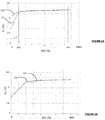
- the correlation data between state of charge SOC and open circuit voltage VOC of battery 1 can be represented by correlation curves.
- two correlation curves C1, C2 are shown for two different battery temperatures, respectively 25 ° C and 10 ° C. It emerges from this Figure 1A that the correlation between the open circuit voltage VOC of the battery 1 and its state of charge SOC does not depend on the temperature over a wide useful range of SOC, here between 10% and 85%.
- the correlation between the open circuit voltage VOC of the battery 1 and its state of charge SOC does not depend either on the state of health or SOH (of the "State Of Health") of the battery, as is apparent of the Figure 1B on which there are shown two correlation curves between the open circuit voltage VOC of the battery 1 and its state of charge SOC, denoted C3 and C4, corresponding to two SOH of the battery respectively equal to 76% and 100%.
- a particular method consists in initially charging the battery 1, preferably to a state of charge of 100%. Once the battery is charged, it is discharged gradually by a succession of discharging operations, spaced by pauses during which the battery is not connected and at rest (without discharge or charge), and the battery voltage decreases and stabilizes due to a relaxation phenomenon within the battery. During each discharge operation, the amount of electric charge delivered by the battery, for example by a coulometric counting method, is measured in order to evaluate the SOC of the battery at the end of the discharge operation.
- the relaxation periods of the battery must be of sufficient duration to reach a complete or almost complete relaxation of the battery and thus obtain a stabilization of the open circuit voltage of the battery.
- each pause between two successive discharge operations has a duration of about 2 hours.
- the duration of breaks may be shorter or longer, depending on the type of battery.
- the open circuit voltage VOC of the battery is measured using a voltage measurement sensor.
- a set of pairs of associated or corresponding SOC and VOC voltage values of the battery is thus obtained.
- the correlation data between the state of charge SOC and the open circuit voltage VOC of the battery 1 could be provided by the manufacturer of the battery.
- the correlation data between the state of charge SOC and the open circuit voltage VOC of the battery 1 can be recorded in a memory of the control device 100, here in the memory 8.
- a memory of the control device 100 here in the memory 8.
- only the open circuit voltage V0 associated with the target state of charge SOC0 is stored in the memory 8.
- the charging method enables the battery 1 to be charged to a predefined target charge state. It is implemented by the load control device 100, under the control of the control module 9.
- the target charge state SOC0 is equal to 70%. It is associated with the target open circuit voltage V0 in the correlation data. It is assumed that initially, before the charging method is implemented, the state of charge of the battery 1 is strictly lower than the target charge state SOC0.
- the control module 9 triggers the start of the charging process.
- the load can be programmed to be triggered automatically at one hour fixed, for example once a day, at a scheduled time. In a first variant, it could be triggered on detecting a state of charge of the battery 1 lower than a fixed minimum charge state. In a second variant, the load is triggered manually, on a user's specific command by means of the user interface 10.
- the method then comprises a step E1 of testing or checking the state of the battery 1 (which may be in a state of charge, rest or discharge) to verify that the battery 1 is not discharged.
- the battery 1 is discharged when it electrically feeds the drive motor 3 of the flap for winding or unrolling.
- Ibatt the current entering the battery 1. It is measured by the sensor 6 '.
- the verification E1 consists in checking whether the current Ibatt is zero (battery at rest) or greater than zero (battery in charge).
- the test E1 is executed by the test module E7, on command of the control module 9.
- step E2 of charging the battery 1.
- the battery 1 is connected to the power source 2, in The photovoltaic module, by closing the switch 5.
- the source 2 provides the battery 1 a load current Ibatt greater than zero. This charging current varies over time, depending on the solar energy recovered by the photovoltaic module 2.
- the voltage measurement sensor 6 measures the voltage Vbatt across the terminals of the battery 1 in charge, during a measurement step E3.
- first voltage is the voltage of the battery 1 measured during charging, the battery being under load current.
- the test module 7 performs a first test E4 intended to detect when the measured voltage Vbatt is equal to or substantially equal to a predetermined target voltage V0, stored in the memory 8.
- This target voltage V0 is equal to the open circuit voltage VOC of the battery 1 when the state of charge of the battery 1 is equal to the target charging state SOC0 (here 70%).
- the target voltage V0 corresponds to the voltage associated with the SOC0 target charge state, here by 70%, in the previously determined correlation data.
- the step E3 for measuring the voltage Vbatt is adapted to enable detection when the voltage Vbatt of the battery under load reaches the target voltage V0.
- the measurement step E3 comprises a succession of measurements made with a sufficiently high sampling frequency, advantageously greater than or equal to one sample per minute.
- a pause step E5 is initiated.
- the charge of the battery 1 is paused, momentarily interrupted.
- the battery 1 is disconnected from the power source 2, by opening the switch 5, in order to interrupt the charge and remains at rest (that is to say, neither charging, neither in landfill).
- the battery 1 is then in the relaxation phase, which has the effect of lowering its voltage Vbatt.
- the pause E5 has a predefined period of time, for example equal to five minutes.
- This period of time is adapted so that the voltage of the battery 1 at the end of the break is close to the voltage final battery after complete relaxation.
- close is meant to mean that the difference between the voltage of the battery at the end of the pause and the final voltage after complete relaxation is less than or equal to 10% of this final voltage.
- the duration of the pause may vary. It is generally greater than or equal to three minutes, advantageously greater than or equal to five minutes.
- the maximum pause time can advantageously be 20 minutes, preferably 15 minutes and still preferably 10 minutes. This limits the overall duration of the charging process. However, the pause time may be greater than the maximum values indicated.
- the voltage of the battery Vbatt is measured by the sensor 6, during a measurement step E6, under the control of the control module 9.
- the method then comprises a second test step E7 consisting in checking whether the voltage of the battery Vbatt measured after the pause E5, in other words of the relaxed battery, satisfies a criterion of end of charge relative to the target voltage V0.
- the end of charge criterion is that the difference between the target voltage V0 and the measured voltage Vbatt after the pause E5 must be less than or equal to a predefined limit deviation ⁇ . In other words, the end of charge criterion is satisfied (positive test E7), if the difference between the target voltage V0 and the second measured voltage Vbatt is less than or equal to the limit difference ⁇ .
- the limit difference ⁇ is preferably less than or equal to 10% of the target voltage V0, advantageously still less than or equal to 5%.
- step E8 of stopping the charge under control of the control module 9.
- the charging process returns to the state test step E1, under the control of the control module 9, the state test E1 being followed , if it is positive, by the following steps E2 to E7 previously described.
- the steps E1 to E7 are thus repeated until the end of charge criterion (difference between the target voltage V0 and the second measured voltage Vbatt2 less than or equal to the limit difference ⁇ ) is satisfied.
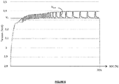
- the evolution of the voltage Vbatt of the battery 1 during the charge process just described, according to an example of implementation, is represented in a simplified manner.
- the figure 4 represents the charge profile of the battery 1 during the implementation of the charging method of the invention according to the first embodiment described.
- the voltage Vbatt of the battery 1 increases continuously until reaching the target voltage V0.
- the voltage Vbatt of the battery 1 oscillates, by the implementation of a succession of alternating charges and pauses, as follows: at each oscillation , the voltage increases to the target voltage V0, during a charging operation E2, then decreases slightly, during a break E5.
- the voltage decreased after each break E5 is gradually approaching the target voltage V0.
- the charge is stopped when the voltage of the battery decreased after a pause is close to the target voltage V0, the difference between these two voltages being less than ⁇ .
- the charging method makes it possible to charge the battery 1 to a target charge state SOC0 equal to 70%. It is assumed that initially, before the charging method is implemented, the state of charge of the battery is strictly lower than the target charging state SOC0.
- control device 100 integrates a time counter 11.
- Step E10 the control device 100 controls the start of the charging process.
- Step E10 is analogous to step E0 previously described.
- the method then comprises a step E12 for testing or checking the state of the battery 1, which battery can be in charge, at rest or in discharge, in order to verify that the battery 1 is not being discharged.
- the E12 test consists of checking whether the current entering the battery 1, Ibatt, is zero (battery at rest) or greater than zero (battery in charge).
- step E20 If the state test E12 is negative (branch N on the figure 5 ), the battery 1 being discharged, the charging process is immediately stopped (step E20).
- step E13 of charging the battery 1.
- the switch 5 under the control of the control module 9, the switch 5 is closed and the battery 1 is connected to the power source 2 (here the photovoltaic module) which delivers a charge current Ibatt strictly greater than zero.
- This charging current Ibatt battery 1 varies over time, depending on the solar energy recovered by the photovoltaic module 2.
- a test step E14 is performed on the charging time in order to check whether the charging time tch has reached a fixed duration ⁇ .
- This duration ⁇ corresponds to the duration of a period or a time interval separating two Successive measurements of the battery voltage 1.
- the duration ⁇ is of the order of a few minutes, in this case of 5 minutes.
- the test E14 consists of checking if tch ⁇ ⁇ .
- test E14 If the test E14 is positive, in other words as soon as the charging time tch is equal to or greater than the duration ⁇ of the measurement period, the control module 9 triggers a measurement of the voltage Vbatt of the battery in charge by the sensor 6, during a first measurement step E15.
- the first step E15 for measuring the voltage Vbatt of the battery 1 under load makes spaced measurements, separated by a fixed time interval, predefined ⁇ .
- This time interval is advantageously greater than or equal to 1 minute, advantageously still greater than or equal to 3 minutes, preferably greater than or equal to 5 minutes. Because of this, the number of measurements of the voltage Vbatt is limited.
- the measurement step E15 is followed by a first test step on the voltage E16.
- the test E16 aims to detect when the voltage Vbatt of the battery measured during step E15 exceeds for the first time the target voltage V0 preset. As a reminder, the target voltage V0 is equal to the open circuit voltage VOC of the battery 1 when the state of charge of the battery 1 is equal to the target charge state (here 70%).
- the control module 9 triggers a break step E17 (branch Y on the figure 5 ).
- pause E17 the charge of the battery 1 is momentarily interrupted.
- the battery 1 is disconnected from the power source 2, here by opening the switch 5, under the control of the control module 9.
- the battery 1 is at rest (it is ie neither in charge nor in discharge). The battery 1 is then in the relaxation phase, which has the effect of lowering the voltage Vbatt.
- the pause E17 has a total predefined duration, for example equal to five minutes.
- This total pause time is adapted so that the voltage of the battery 1 at the end of the pause period is close to the final theoretical voltage of the battery after a complete relaxation requiring a pause of several hours, ie the voltage that the battery would reach theoretically if it was totally relaxed.
- close is meant to mean that the difference between the voltage of the battery at the end of the pause and the final voltage after complete relaxation is less than or equal to 10% of this final voltage.
- the duration of the pause may vary. It is generally greater than or equal to three minutes, advantageously greater than or equal to five minutes.
- the maximum pause time can advantageously be 20 minutes, preferably 15 minutes and still preferably 10 minutes. This limits the overall duration of the charging process.
- the pause time may be greater than the maximum values indicated.
- the pause step E17 is split into two successive pauses E170, E173.
- the first break E170 is short-lived. Its duration d1 is less than the duration d2 of the second break E173.
- the duration d1 of the first pause step is one minute and the duration d2 of the second break E173 is four minutes.
- the duration d1 of the first pause is advantageously less than or equal to 2 minutes, advantageously still less than or equal to 1 minute.
- the sum of the respective durations d1 and d2 of the two pauses E170 and E173 is equal to the fixed pause time.
- the voltage of the battery Vbatt is measured in a step E171 by the sensor 6. Then the test module 7 performs an intermediate test step E172 to verify whether the measured voltage Vbatt is always greater than or equal to the target voltage V0.
- the control device 100 implements the second pause step E173 of a duration d2.
- the second pause E173 is performed only if the intermediate test is positive, ie only if the voltage Vbatt after the first pause is always greater than the target voltage V0.
- This alternative embodiment reduces the total time of pause during charging to maximize the solar energy during charging.
- the voltage of the battery Vbatt is measured by the sensor 6, during a measurement step E18.
- step E17 could comprise only one pause of duration of pause.
- the method then comprises a test step E19 consisting in checking whether the voltage Vbatt measured during the step E18, in other words the battery voltage after the pause E17, satisfies a criterion of end of charge.
- This step is implemented by the test module 7, under the control of the control module 9.
- the end of charge criterion is that the voltage Vbatt of the battery 1 measured after the pause E17, and therefore after relaxation, must be greater than or equal to the target voltage V0. In other words, the end of charge criterion is satisfied (test E19 positive) if the voltage Vbatt of the battery 1 after the pause E17 is greater than or equal to the target voltage V0.
- test E19 is positive (branch Y on the figure 5 ), ie if the voltage Vbatt of the battery 1 after the pause E17 is greater than or equal to the target voltage V0, the charging process is stopped (step E20 of stopping the charge).
- the steps E12 and following are then repeated.
- the figure 6 represents the charge profile of the battery 1 during the implementation of the charging method of the invention according to the second embodiment.
- the voltage Vbatt of the battery 1 increases continuously until slightly exceed the target voltage V0.
- the voltage Vbatt of the battery 1 oscillates around the target voltage V0, by a succession of charging operations separated by pauses.
- the voltage Vbatt increases and exceeds the target voltage V0, during each charging operation, then decreases during each pause by going back below the target voltage V0.
- the charge is stopped as soon as the voltage of the battery decreased after a pause remains higher than the target voltage V0.
- the target state of charge is 70%.
- the target state of charge of the battery could be between 30% and 85%, advantageously still between 50% and 80%, advantageously still between 65% and 75%.
- the invention can be applied to any type of power source. It finds an interesting application for a variable current power source but could also apply to a fixed current power source.
- the power source is not limited to a photovoltaic module. It could use any other renewable energy source and be adapted to generate a charging electric current from this renewable energy source.
- the battery 1 is intended to charge the drive motor 4 with a mobile closure, concealment, sun protection or screen element.
- the invention could be applied to any other element to supply electrical energy using the battery 1, for example a parking meter, a street lamp or other street furniture, or even a door or window motor.
- the invention therefore also relates to a system comprising an element for supplying electrical energy, a battery of electrochemical accumulators, in particular a lithium battery, intended to be charged by connection to an external power source and to supply electrical energy to this element. , and a device for controlling the charge of the battery as previously described.
- the present invention can be applied to any type of battery, especially Lithium batteries such as Lithium-Ion batteries, but also lead batteries, NiMH.
Abstract
Le procédé permet de charger une batterie d'accumulateurs électrochimiques, notamment une batterie lithium, à l'aide d'une source d'alimentation. Il comprend une étape de charge de la batterie par connexion à la source d'alimentation ; une première étape de mesure d'une tension de la batterie en charge ; un premier test permettant de détecter si la tension mesurée de la batterie en charge est égale ou supérieure à une tension cible ; si le premier test est positif, une étape de pause, ayant une durée prédéfinie, durant laquelle la batterie est déconnectée de la source d'alimentation et au repos ; une deuxième étape de mesure de la tension de la batterie en fin de pause ; un deuxième test consistant à vérifier si la tension de la batterie mesurée en fin de pause satisfait un critère de fin de charge relatif à la tension cible.The method can charge a battery of electrochemical accumulators, including a lithium battery, using a power source. It includes a step of charging the battery by connection to the power source; a first step of measuring a voltage of the battery in charge; a first test for detecting whether the measured voltage of the battery under charge is equal to or greater than a target voltage; if the first test is positive, a pause step, having a predefined duration, during which the battery is disconnected from the power source and at rest; a second step of measuring the voltage of the battery at the end of the pause; a second test consisting of checking whether the voltage of the battery measured at the end of the pause satisfies a criterion of end of charge relative to the target voltage.
Description
L'invention concerne un procédé de charge d'une batterie à accumulateurs électrochimiques, notamment une batterie lithium, et un dispositif de pilotage de la charge de la batterie. Elle concerne aussi une application particulière d'un tel dispositif de pilotage de la charge à un système de commande d'un élément mobile de fermeture, d'occultation, de protection solaire ou d'écran.The invention relates to a method for charging a battery with electrochemical accumulators, in particular a lithium battery, and a device for controlling the charge of the battery. It also relates to a particular application of such a device for controlling the load to a control system of a movable closure element, occultation, sun protection or screen.
Le vieillissement d'une batterie lithium, ou plus généralement d'une batterie d'accumulateurs électrochimiques, est fortement accéléré lorsque la batterie est totalement ou quasi-totalement chargée, même en dehors de toute utilisation de la batterie. Afin de ralentir ce vieillissement et donc augmenter la durée de vie de la batterie, une solution consiste à ne pas charger pleinement la batterie et à arrêter la charge lorsque la batterie a atteint un état de charge, ou SOC (State of Charge), cible strictement inférieur à 100%.The aging of a lithium battery, or more generally of an electrochemical accumulator battery, is greatly accelerated when the battery is totally or almost totally charged, even when no use is made of the battery. In order to slow down this aging and thus increase the life of the battery, one solution is to not fully charge the battery and stop the charge when the battery has reached a state of charge, or SOC (State of Charge), target strictly less than 100%.
Il existe différentes méthodes connues pour arrêter la charge d'une batterie à un état de charge cible ou souhaité.There are various known methods for stopping charging a battery to a target or desired state of charge.
Une première méthode, décrite dans le document
- elle requiert une capacité de stockage importante et des moyens de traitement ;
- elle nécessite une adaptation régulière des cartographies pour tenir compte du vieillissement de la batterie.
- it requires a large storage capacity and processing means;
- it requires a regular adaptation of the maps to take account of the aging of the battery.
Une deuxième méthode connue repose sur le comptage coulométrique. Le courant de charge de la batterie est mesuré et intégré dans le temps à l'aide de moyens logiciels et/ou matériels. La température et le régime de charge ayant une influence sur le traitement et l'état de charge issu du comptage de coulombs, cette méthode utilise également des cartographies pour prendre en compte ces influences. Une telle solution est coûteuse en matériel et en emplacement mémoire. En revanche, elle ne nécessite pas de modifier au cours de la vie de la batterie les cartographies qui sont indépendantes du vieillissement de la celle-ci.A second known method relies on coulometric counting. The charging current of the battery is measured and integrated over time using software and / or hardware means. The temperature and the load regime having an influence on the treatment and the state of charge resulting from the counting of coulombs, this method also uses cartographies to take into account these influences. Such a solution is expensive in hardware and memory location. On the other hand, it does not require to modify during the life of the battery the cartographies which are independent of the aging of this one.
Les méthodes connues nécessitent de nombreuses mesures (courant, température) et d'importantes ressources en mémoire et en traitement et/ou calcul. Or, pour certaines applications, on peut souhaiter mettre en oeuvre une méthode plus simple et plus économique en capacité de stockage, en puissance de calcul et/ou en mesures.The known methods require numerous measurements (current, temperature) and important resources in memory and in processing and / or calculation. However, for some applications, one may wish to implement a simpler and more economical method in storage capacity, computing power and / or measurements.
La présente invention vient améliorer la situation.The present invention improves the situation.
A cet effet, l'invention concerne un procédé de charge d'une batterie d'accumulateurs électrochimiques, notamment une batterie lithium, à l'aide d'une source d'alimentation, caractérisé en ce qu'il comprend
- une étape de charge de la batterie par connexion à la source d'alimentation ;
- une première étape de mesure d'une tension de la batterie en charge ;
- un premier test permettant de détecter si la tension mesurée de la batterie en charge est égale ou supérieure à une tension cible qui est égale à une tension en circuit ouvert de la batterie à un état de charge cible souhaité ;
- si le premier test est positif, une étape de pause, ayant une durée prédéfinie, durant laquelle la batterie est déconnectée de la source d'alimentation et au repos ;
- une deuxième étape de mesure de la tension de la batterie en fin de pause ;
- un deuxième test consistant à vérifier si la tension de la batterie mesurée en fin de pause satisfait un critère de fin de charge relatif à la tension cible ;
- si le deuxième test est positif, le procédé de charge est arrêté ;
- si le deuxième test est négatif, l'étape de charge est réitérée.
- a step of charging the battery by connection to the power source;
- a first step of measuring a voltage of the battery in charge;
- a first test for detecting whether the measured voltage of the battery under charge is equal to or greater than a target voltage which is equal to an open circuit voltage of the battery at a desired target charge state;
- if the first test is positive, a pause step, having a predefined duration, during which the battery is disconnected from the power source and at rest;
- a second step of measuring the voltage of the battery at the end of the pause;
- a second test consisting in checking whether the voltage of the battery measured at the end of the pause satisfies a criterion of end of charge relative to the target voltage;
- if the second test is positive, the charging process is stopped;
- if the second test is negative, the charging step is repeated.
Avantageusement, tant que le premier test est négatif, autrement dit tant que la tension de la batterie en charge est strictement inférieure à la tension cible, les étapes de charge et de mesure sont exécutées.Advantageously, as long as the first test is negative, in other words as long as the voltage of the battery under charge is strictly lower than the target voltage, the charging and measuring steps are executed.
L'invention permet de charger la batterie jusqu'à un état de charge égal ou sensiblement égal à un état de charge cible souhaité, en procédant uniquement à des mesures de la tension de la batterie. Elle ne nécessite pas de ressources de traitement et de calcul importantes. Généralement, le critère de fin de charge relatif à la tension cible est atteint progressivement par une succession de charges et de pauses alternées, la tension de la batterie après la pause, et donc après relaxation, se rapprochant petit à petit de la tension cible.The invention enables the battery to be charged to a state of charge equal to or substantially equal to a desired target charge state by taking only measurements of the battery voltage. It does not require significant processing and computing resources. Generally, the end of charge criterion relating to the target voltage is progressively achieved by a succession of alternating charges and pauses, the voltage of the battery after the break, and therefore after relaxation, getting closer to the target voltage.
Dans un premier mode de réalisation, lors du premier test, on détecte lorsque ladite tension de la batterie en charge atteint ladite tension cible, et en ce que le critère de fin de charge est que l'écart entre la tension cible et la tension mesurée de la batterie en fin de pause doit être inférieur ou égal à un écart limite prédéfini.In a first embodiment, during the first test, it is detected when said voltage of the battery under charge reaches said target voltage, and in that the end of charge criterion is that the difference between the target voltage and the measured voltage the battery at the end of the pause must be less than or equal to a predefined limit deviation.
Dans ce premier mode de réalisation, dès qu'il est détecté pendant la charge que la tension de la batterie a atteint la tension cible, on déclenche une pause et, après la pause, on teste de nouveau la tension de la batterie, diminuée du fait du phénomène de relaxation. Si l'écart entre la tension de la batterie après la pause et la tension cible est suffisamment faible (c'est-à-dire inférieur à l'écart limite fixé), la charge est arrêtée car il est estimé que l'état de charge de la batterie est alors égal ou très proche (par exemple à 10% près) de l'état de charge cible souhaité. Si l'écart entre la tension de la batterie après la pause et la tension cible est trop important (c'est-à-dire supérieur à l'écart limite fixé), la charge est reprise de la même manière que précédemment, c'est-à-dire avec une interruption momentanée de la charge pour réaliser une pause dès que la tension de la batterie atteint de nouveau la tension cible puis, après la pause, la réalisation d'un test pour vérifier si l'écart limite entre la tension de la batterie après la pause et la tension cible est suffisamment faible.In this first embodiment, as soon as it is detected during charging that the voltage of the battery has reached the target voltage, a pause is initiated and, after the pause, the battery voltage is tested again, minus the does the phenomenon of relaxation. If the difference between the battery voltage after the pause and the target voltage is sufficiently small (ie less than the set limit deviation), the load is stopped because it is estimated that the charge of the battery is then equal to or very close (for example within 10%) of the desired target charge state. If the difference between the voltage of the battery after the pause and the target voltage is too great (ie greater than the fixed limit deviation), the charge is resumed in the same way as previously, it that is to say with a momentary interruption of the charge to pause as soon as the battery voltage reaches the target voltage again and then, after the pause, the performance of a test to check whether the limit difference between the battery voltage after the pause and the target voltage is sufficiently low.
Avantageusement, la première étape de mesure comprend une succession de mesures réalisées concomitamment à l'étape de charge, avec une fréquence d'échantillonnage d'au moins un échantillon par minute. Grâce à cela, on détecte avec une précision souhaitée le moment où la tension de la batterie atteint la tension cible (ou une tension sensiblement égale à la tension cible).Advantageously, the first measurement step comprises a succession of measurements carried out concomitantly with the charging step, with a sampling frequency of at least one sample per minute. With this, it is detected with a desired accuracy when the battery voltage reaches the target voltage (or a voltage substantially equal to the target voltage).
Ledit écart limite est avantageusement inférieur ou égal à 10% de la tension cible, avantageusement encore inférieure ou égal à 5%.Said limit difference is advantageously less than or equal to 10% of the target voltage, advantageously still less than or equal to 5%.
La durée de l'étape de pause est avantageusement :
- supérieure à trois minutes, avantageusement égale ou supérieure à cinq minutes ;
- inférieure ou égale à 20 minutes, de préférence inférieure ou égale à 15 minutes et encore avantageusement inférieure ou égale à 10 minutes.
- greater than three minutes, advantageously equal to or greater than five minutes;
- less than or equal to 20 minutes, preferably less than or equal to 15 minutes and still advantageously less than or equal to 10 minutes.
Dans un deuxième mode de réalisation, la première étape de mesure de la tension de la batterie en charge réalise des mesures espacées, séparées par un intervalle de temps fixé supérieur ou égal à 1 minute, avantageusement supérieur ou égal à 3 minutes, avantageusement encore supérieur ou égal à 5 minutes, et le premier test est destiné à détecter lorsque la tension mesurée de la batterie en charge dépasse pour la première fois ladite tension cible.In a second embodiment, the first step of measuring the voltage of the battery under charge makes spaced measurements, separated by a fixed time interval greater than or equal to 1 minute, advantageously greater than or equal to 3 minutes, advantageously even greater or equal to 5 minutes, and the first test is for detecting when the measured voltage of the charged battery exceeds for the first time said target voltage.
Avantageusement, l'étape de pause comprend :
- une première pause, suivie d'une étape de mesure de la tension de la batterie et d'une étape de test intermédiaire pour vérifier si la tension mesurée après la première pause est supérieure ou égale à la tension cible, et
- une deuxième pause mise en oeuvre seulement si le test intermédiaire est positif,
- a first pause, followed by a step of measuring the voltage of the battery and an intermediate test step to check if the voltage measured after the first pause is greater than or equal to the target voltage, and
- a second pause implemented only if the intermediate test is positive,
Avantageusement encore, si le test intermédiaire est négatif, l'étape de charge est réitérée directement après la première pause.Advantageously, if the intermediate test is negative, the charging step is repeated directly after the first pause.
Suite à la première pause, si la tension de la batterie passe en dessous de la tension cible, la charge est reprise. La charge n'est arrêtée qu'une fois que la tension de la batterie après la pause demeure supérieure ou égale à la tension cible.After the first pause, if the battery voltage drops below the target voltage, the charge is resumed. The charge is stopped only after the battery voltage after the pause remains greater than or equal to the target voltage.
La durée de la première pause est avantageusement inférieure ou égale à 2 minutes, avantageusement encore inférieure ou égale à 1 minute.The duration of the first pause is advantageously less than or equal to 2 minutes, advantageously still less than or equal to 1 minute.
L'état de charge cible de la batterie peut être compris entre 30% et 85%, avantageusement entre 50% et 80%, avantageusement encore entre 65% et 75%. Grâce à cela, le vieillissement de la batterie est ralenti et sa durée de vie est donc augmentée.The target charging state of the battery may be between 30% and 85%, advantageously between 50% and 80%, and advantageously between 65% and 75%. Thanks to this, the aging of the battery is slowed down and its life is increased.
Avantageusement encore, le procédé comprend une étape préalable de configuration lors de laquelle on détermine des données de corrélation entre l'état de charge de la batterie et la tension en circuit ouvert de la batterie. Cette étape de configuration peut être réalisée en laboratoire ou en usine, sur la batterie elle-même ou sur une batterie de référence identique.Advantageously, the method comprises a preliminary configuration step in which correlation data are determined between the state of charge of the battery and the open circuit voltage of the battery. This configuration step can be performed in the laboratory or in the factory, on the battery itself or on an identical reference battery.
La source d'alimentation est avantageusement agencée pour délivrer un courant variable. Elle peut comprend un dispositif de production d'énergie électrique intermittente.The power source is advantageously arranged to deliver a variable current. It may include a device for producing intermittent electrical energy.
La source d'alimentation peut être agencée pour générer un courant électrique de charge à partir d'une source d'énergie renouvelable. Elle peut comprend un module photovoltaïque.The power source can be arranged to generate an electric charge current from a renewable energy source. It can includes a photovoltaic module.
L'invention concerne aussi un dispositif de pilotage de la charge d'une batterie d'accumulateurs électrochimiques, notamment une batterie lithium, à l'aide d'une source d'alimentation, destiné à charger ladite batterie jusqu'à un état de charge cible prédéfini, caractérisé en ce qu'il comprend :
- un élément pilotable de connexion et de déconnexion de la batterie à la source d'alimentation ;
- un capteur de mesure de la tension de la batterie ;
- un module de test de la tension mesurée reliée à une mémoire de stockage d'une tension cible égale à la tension en circuit ouvert de la batterie à un état de charge cible souhaité ;
- un module de commande destiné à commander l'élément pilotable de connexion et de déconnexion, le capteur de mesure de la tension et le module de test pour mettre en oeuvre le procédé tel que précédemment défini.
- a controllable element for connecting and disconnecting the battery to the power source;
- a sensor for measuring the voltage of the battery;
- a measured voltage test module connected to a storage memory of a target voltage equal to the open circuit voltage of the battery to a desired target charge state;
- a control module for controlling the controllable connection and disconnection element, the voltage measurement sensor and the test module for implement the method as defined above.
L'invention concerne aussi un système comportant un élément à alimenter en énergie électrique, une batterie d'accumulateurs électrochimiques, notamment une batterie lithium, destinée à être chargée par connexion à une source d'alimentation externe et à alimenter en énergie électrique ledit élément, et un dispositif de pilotage de la charge de la batterie tel que défini ci-dessus.The invention also relates to a system comprising an element for supplying electrical energy, a battery of electrochemical accumulators, in particular a lithium battery, intended to be charged by connection to an external power source and to supply electrical energy to said element, and a device for controlling the charge of the battery as defined above.
Dans un mode de réalisation particulier, l'élément à alimenter en énergie électrique est un moteur d'entraînement d'un élément mobile de fermeture, d'occultation, de protection solaire ou d'écran.In a particular embodiment, the element to supply electrical energy is a driving motor of a movable element for closing, concealment, sun protection or screen.
L'invention concerne enfin une installation comprenant un élément mobile de fermeture, d'occultation, de protection solaire ou d'écran et le système défini ci-dessus. Dans une forme de réalisation particulière, l'installation comprend une source d'alimentation agencée pour générer un courant électrique de charge à partir d'une source d'énergie renouvelable, notamment un module photovoltaïque.Finally, the invention relates to an installation comprising a movable closure member, occultation, sun protection or screen and the system defined above. In a particular embodiment, the installation comprises a power source arranged to generate an electric charge current from a renewable energy source, in particular a photovoltaic module.
L'invention sera mieux comprise à l'aide de la description suivante du procédé de charge d'une batterie, d'un dispositif de pilotage de la charge d'une batterie et d'une installation intégrant une batterie et un tel dispositif de pilotage, selon différents variantes de réalisation de l'invention, en référence aux dessins annexés sur lesquels :
- les
figures 1A et 1B représentent des courbes de corrélation entre l'état de charge (SOC) et la tension en circuit ouvert de la batterie, respectivement pour différentes températures de la batterie et pour différents états de santé (SOH) de la batterie ; - la
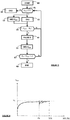
figure 2 représente un schéma d'une installation intégrant la batterie ; - la
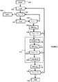
figure 3 représente un organigramme du procédé de charge selon un premier mode de réalisation de l'invention ; - la
figure 4 représente l'évolution de la tension de la batterie lors d'une charge selon le procédé de lafigure 3 ; - la
figure 5 représente un organigramme du procédé de charge selon un deuxième mode de réalisation de l'invention ; - la
figure 6 représente l'évolution de la tension de la batterie lors d'une charge selon le procédé de lafigure 4 .
- the
Figures 1A and 1B represent correlation curves between the state of charge (SOC) and the open circuit voltage of the battery, respectively for different battery temperatures and for different states of health (SOH) of the battery; - the
figure 2 represents a diagram of an installation integrating the battery; - the
figure 3 represents a flowchart of the charging method according to a first embodiment of the invention; - the
figure 4 represents the evolution of the voltage of the battery during a charge according to the method of thefigure 3 ; - the
figure 5 represents a flowchart of the charging method according to a second embodiment of the invention; - the
figure 6 represents the evolution of the voltage of the battery during a charge according to the method of thefigure 4 .
L'invention permet de charger une batterie d'accumulateurs électrochimiques 1, notamment une batterie lithium, jusqu'à un état de charge cible strictement inférieur à 100%, noté SOCcible. L'état de charge cible SOCcible est par exemple égal à 70%.The invention makes it possible to charge a battery of
La batterie 1 est par exemple une batterie lithium-ion. Dans l'exemple de réalisation particulier décrit ici, elle est alimentée en énergie électrique par un module photovoltaïque 2. A titre d'exemple illustratif d'application, la batterie 1 peut équiper une installation 200 de type « volet solaire » qui récupère l'énergie solaire grâce au module photovoltaïque 2 placé par exemple sur le coffre du volet.The
L'installation 200 comprend les éléments suivants :
un volet roulant 3 ;un dispositif 4 d'actionnement du volet roulant 3, comportant un moteur d'entraînement en déplacement du volet roulant 3 ;- la batterie lithium-
ion 1 d'alimentation électrique du moteur ; le module photovoltaïque 2 ;un dispositif 100 de pilotage de la charge de labatterie 1 ;- une unité de commande 20.
- a
shutter 3; - a
device 4 for actuating theshutter 3, comprising a drive motor moving theshutter 3; - the lithium-
ion battery 1 power supply motor; - the
photovoltaic module 2; - a
device 100 for controlling the charge of thebattery 1; - a
control unit 20.
L'invention pourrait s'appliquer à tout autre élément mobile de fermeture, d'occultation, de protection solaire ou d'écran, à la place du volet roulant.The invention could be applied to any other movable closure element, occultation, sun protection or screen, instead of the shutter.
La batterie 1 a pour rôle d'alimenter électriquement le moteur. En outre, ici elle a également pour rôle d'alimenter les différents éléments électriques de l'installation 200, notamment le dispositif de pilotage 100 et l'unité de commande 20. L'installation 200 est ainsi autonome sur le plan énergétique.The
L'énergie électrique produite par le module photovoltaïque 2 à partir de l'énergie solaire récupérée permet de charger la batterie 1 à l'aide d'un courant électrique de charge qui est variable (c'est-à-dire qui varie dans le temps). Selon l'invention, la batterie est chargée par le module photovoltaïque 2 par la mise en oeuvre d'un procédé de charge, décrit plus loin, permettant de charger la batterie 1 jusqu'à un état de charge cible SOC0 prédéfini de façon simple et économique, sans ressources importantes de calculs et de mémoires.The electrical energy produced by the
L'unité de commande 20 de l'installation 200 est reliée aux différents éléments de l'installation et destinée à contrôler le fonctionnement de ces éléments. Elle comprend ici un microprocesseur. Elle a notamment pour rôle de commander le fonctionnement du moteur 4 d'entraînement du volet roulant 3 et le dispositif 100 de pilotage de la charge de la batterie 1.The
Le dispositif de pilotage de la charge 100 comprend :
- un élément pilotable 5 de connexion et de déconnexion de la batterie 1
au module photovoltaïque 2, en l'espèce un interrupteur, interposé entre la batterie 1 et lemodule photovoltaïque 2 ; un capteur 6 de mesure de la tension de labatterie 1 ;- ici un capteur 6' de mesure du courant entrant dans
la batterie 1 ; - un module de test 7, relié aux capteurs 6 et 6' et destiné à réaliser des tests sur la tension ou le courant mesurés par les capteurs ;
- une mémoire de stockage 8, stockant notamment une tension cible V0, reliée au module de test 7 ;
- un module de commande 9.
- a controllable element 5 for connection and disconnection of the
battery 1 to thephotovoltaic module 2, in this case a switch, interposed between thebattery 1 and thephotovoltaic module 2; - a
sensor 6 for measuring the voltage of thebattery 1; - here a sensor 6 'for measuring the current entering the
battery 1; - a test module 7, connected to the
sensors 6 and 6 'and intended to perform tests on the voltage or current measured by the sensors; - a
storage memory 8, in particular storing a target voltage V0, connected to the test module 7; - a
control module 9.
Le module de commande 9 est ici relié à l'unité centrale de commande 20. Dans l'exemple de réalisation particulier décrit ici, le module de commande 20 est un module logiciel comportant des instructions logicielles destinées à être exécutées par l'unité centrale de commande 20 afin de piloter la charge de la batterie selon le procédé de l'invention. En variante, le dispositif de pilotage 100 pourrait comprendre une unité de traitement, telle qu'un microprocesseur, distincte de l'unité de commande 20.The
Le module de commande 9 a pour fonction de contrôler le fonctionnement de l'élément pilotable de connexion/déconnexion 5, du capteur de mesure de tension 6 et du module de test 7 de manière à mettre en oeuvre le procédé de charge de la batterie 1 de l'invention.The function of the
Le dispositif de pilotage 100 peut également comprendre une interface utilisateur 10 comportant des moyens logiciels et matériels permettant de saisir et de restituer des informations. Elle permet notamment à un utilisateur de saisir des instructions de charge (par exemple une instruction de charge manuelle ou une instruction de programmation de charges) ou d'autres données utiles pour la charge de la batterie (par exemple un état de charge cible de la batterie 1). Ces instructions et données sont ici enregistrées dans la mémoire de stockage 8.The
L'ensemble comportant le moteur d'entraînement 4, la batterie d'alimentation 1, le dispositif 100 de pilotage de la charge de la batterie 1 et l'unité de commande 20 forme un système destiné à commander le volet roulant 3.The assembly comprising the driving
Le procédé de charge de la batterie 1 comprend une étape préalable de configuration CONFIG lors de laquelle des données de corrélation entre l'état de charge ou SOC de la batterie 1 et la tension en circuit ouvert VOC de la batterie 1 sont déterminées. Cette étape de configuration peut être réalisée en usine ou en laboratoire, préalablement à l'installation de la batterie 1 sur site. Elle peut être réalisée sur la batterie 1 elle-même ou sur une batterie de référence identique à la batterie 1.The method of charging the
Les données de corrélation entre état de charge SOC et tension en circuit ouvert VOC de la batterie 1 peuvent être représentées par des courbes de corrélation. Sur la
Pour obtenir ces données de corrélation, une méthode particulière consiste à charger initialement la batterie 1, de préférence jusqu'à un état de charge de 100%. Une fois la batterie chargée, on la décharge de façon progressive par une succession d'opérations de décharge, espacées par des pauses durant lesquelles la batterie est non connectée et au repos (sans décharge ou charge), et la tension de la batterie diminue et se stabilise du fait d'un phénomène de relaxation au sein de la batterie. Lors de chaque opération de décharge, on mesure la quantité de charge électrique délivrée par la batterie, par exemple par une méthode de comptage coulométrique, afin d'évaluer le SOC de la batterie à la fin de l'opération de décharge. Les pauses de relaxation de la batterie doivent être d'une durée suffisante pour atteindre une relaxation complète ou quasi-complète de la batterie et ainsi obtenir une stabilisation de la tension en circuit ouvert de la batterie. Par exemple, chaque pause séparant deux opérations de décharge successives a une durée d'environ 2 heures. La durée des pauses pourrait toutefois être plus courte ou plus longue, selon le type de batterie. A l'issue de chaque pause entre deux décharges, la tension en circuit ouvert VOC de la batterie est mesurée à l'aide d'un capteur de mesure de tension. On obtient ainsi un ensemble de couples de valeurs associées ou correspondantes de SOC et de tension VOC de la batterie. Par extrapolation, on peut en déduire les données de corrélation entre le SOC et la tension VOC de la batterie sur toute la plage de SOC analysée, allant de préférence de 100% à 0%.To obtain these correlation data, a particular method consists in initially charging the
Les données de corrélation entre l'état de charge SOC et la tension en circuit ouvert VOC de la batterie 1 pourraient être fournies par le fabricant de la batterie.The correlation data between the state of charge SOC and the open circuit voltage VOC of the
Les données de corrélation entre l'état de charge SOC et la tension en circuit ouvert VOC de la batterie 1 peuvent être enregistrées dans une mémoire du dispositif de pilotage 100, ici dans la mémoire 8. En variante, seule la tension en circuit ouvert V0 associée à l'état de charge cible SOC0 est enregistrée dans la mémoire 8.The correlation data between the state of charge SOC and the open circuit voltage VOC of the
On va maintenant décrire, en référence à la
Lors d'une étape initiale E0, le module de commande 9 déclenche le démarrage du procédé de charge. La charge peut être programmée pour être déclenchée de façon automatique à une heure fixée, par exemple une fois par jour, à une heure programmée. Dans une première variante, elle pourrait être déclenchée sur détection d'un état de charge de la batterie 1 inférieur à un état de charge minimal fixé. Dans une deuxième variante, la charge est déclenchée de façon manuelle, sur commande spécifique d'un utilisateur au moyen de l'interface utilisateur 10.During an initial step E0, the
Le procédé comprend ensuite une étape E1 de test ou de vérification de l'état de la batterie 1 (qui peut être dans un état de charge, de repos ou de décharge) afin de vérifier que la batterie 1 n'est pas en décharge. Par exemple, la batterie 1 est en décharge lorsqu'elle alimente électriquement le moteur 3 d'entraînement du volet pour l'enrouler ou le dérouler. Notons « Ibatt » le courant entrant dans la batterie 1. Il est mesuré par le capteur 6'. La vérification E1 consiste à vérifier si le courant Ibatt est nul (batterie au repos) ou supérieur à zéro (batterie en charge). Le test E1 est exécuté par le module de test E7, sur commande du module de commande 9.The method then comprises a step E1 of testing or checking the state of the battery 1 (which may be in a state of charge, rest or discharge) to verify that the
Si le test d'état est négatif (branche N sur la
Si le test d'état est positif (branche Y sur la
Durant l'étape de charge E2, le capteur de mesure de tension 6 mesure la tension Vbatt aux bornes de la batterie 1 en charge, lors d'une étape de mesure E3. Par définition, on appelle « première tension » la tension de la batterie 1 mesurée pendant la charge, la batterie étant sous courant de charge.During the charging step E2, the
Parallèlement aux étapes de charge E2 et de mesure E3, sous la commande du module de commande 9, le module de test 7 exécute un premier test E4 destiné à détecter lorsque la tension mesurée Vbatt est égale ou sensiblement égale à une tension cible V0 prédéfinie, mémorisée dans la mémoire 8. Cette tension cible V0 est égale à la tension en circuit ouvert VOC de la batterie 1 lorsque l'état de charge de la batterie 1 est égal à l'état de charge cible SOC0 (ici 70%). Autrement dit, la tension cible V0 correspond à la tension associée à l'état de charge cible SOC0, ici de 70%, dans les données de corrélation précédemment déterminées.In parallel with the steps of charging E2 and measuring E3, under the control of the
L'étape E3 de mesure de la tension Vbatt est adaptée pour permettre de détecter lorsque la tension Vbatt de la batterie en charge atteint la tension cible V0. Par exemple, l'étape de mesure E3 comprend une succession de mesures réalisées avec une fréquence d'échantillonnage suffisamment élevée, avantageusement supérieure ou égale à un échantillon par minute.The step E3 for measuring the voltage Vbatt is adapted to enable detection when the voltage Vbatt of the battery under load reaches the target voltage V0. For example, the measurement step E3 comprises a succession of measurements made with a sufficiently high sampling frequency, advantageously greater than or equal to one sample per minute.
Tant que le test E4 est négatif (branche N sur la
Si le test E4 est positif (branche Y sur la
A l'issue de l'étape de pause E5, la tension de la batterie Vbatt est mesurée par le capteur 6, lors d'une étape de mesure E6, sous la commande du module de commande 9.At the end of the pause step E5, the voltage of the battery Vbatt is measured by the
Le procédé comprend ensuite une deuxième étape de test E7 consistant à vérifier si la tension de la batterie Vbatt mesurée après la pause E5, autrement dit de la batterie relaxée, satisfait un critère de fin de charge relatif à la tension cible V0. Dans le premier mode de réalisation décrit ici, le critère de fin de charge est que l'écart entre la tension cible V0 et la tension mesurée Vbatt après la pause E5 doit être inférieur ou égal à un écart limite prédéfini ε. Autrement dit, le critère de fin de charge est satisfait (test E7 positif), si l'écart entre la tension cible V0 et la deuxième tension mesurée Vbatt est inférieur ou égal à l'écart limite ε.The method then comprises a second test step E7 consisting in checking whether the voltage of the battery Vbatt measured after the pause E5, in other words of the relaxed battery, satisfies a criterion of end of charge relative to the target voltage V0. In the first embodiment described here, the end of charge criterion is that the difference between the target voltage V0 and the measured voltage Vbatt after the pause E5 must be less than or equal to a predefined limit deviation ε. In other words, the end of charge criterion is satisfied (positive test E7), if the difference between the target voltage V0 and the second measured voltage Vbatt is less than or equal to the limit difference ε.
L'écart limite ε est de préférence inférieur ou égal à 10% de la tension cible V0, avantageusement encore inférieure ou égal à 5%.The limit difference ε is preferably less than or equal to 10% of the target voltage V0, advantageously still less than or equal to 5%.
Si le test E7 est positif (branche Y sur la
Si le test E7 est négatif (branche N sur la
Sur la
On va maintenant décrire en référence aux
Dans l'exemple de réalisation décrit ici, non limitatif, le procédé de charge permet de charger la batterie 1 jusqu'à un état de charge cible SOC0 égal à 70%. On suppose qu'initialement, avant la mise en oeuvre du procédé de charge, l'état de charge de la batterie est strictement inférieur à l'état de charge cible SOC0.In the embodiment described here, which is not limiting, the charging method makes it possible to charge the
Pour la mise en oeuvre de ce deuxième mode de réalisation du procédé de charge, le dispositif de pilotage 100 intègre un compteur de temps 11.For the implementation of this second embodiment of the charging method, the
Lors d'une étape initiale E10, le dispositif de pilotage 100 commande le démarrage du procédé de charge. L'étape E10 est analogue à l'étape E0 précédemment décrite. Suite au démarrage de la charge, le dispositif de pilotage 100 déclenche un compteur de temps de charge tch lors d'une étape E11. Initialement, le temps de charge tch est nul (tch=0).During an initial step E10, the
Le procédé comprend ensuite une étape E12 de test ou de vérification de l'état de la batterie 1, celle-ci pouvant être en charge, au repos ou en décharge, afin de vérifier que la batterie 1 n'est pas en cours de décharge. Le test E12 consiste à vérifier si le courant entrant dans la batterie 1, Ibatt, est nul (batterie au repos) ou supérieur à zéro (batterie en charge).The method then comprises a step E12 for testing or checking the state of the
Si le test d'état E12 est négatif (branche N sur la
Si le test d'état E12 est positif (branche Y sur la
Durant l'étape de charge E13, on réalise une étape de test E14 sur le temps de charge afin de vérifier si le temps de charge tch a atteint une durée fixée τ. Cette durée τ correspond à la durée d'une période ou d'un intervalle de temps séparant deux mesures successives de la tension de la batterie 1. Par exemple, la durée τ est de l'ordre de quelques minutes, ici de 5 minutes. Autrement dit, le test E14 consiste à vérifier si tch ≥ τ.During the charging step E13, a test step E14 is performed on the charging time in order to check whether the charging time tch has reached a fixed duration τ. This duration τ corresponds to the duration of a period or a time interval separating two Successive measurements of the
Tant que le test E14 est négatif, autrement dit tant que le temps de charge tch reste inférieur à la durée τ de la période de mesure, le procédé revient à l'étape de test d'état E12 et la charge E13 est poursuivie tant que ce test d'état E12 est positif.As long as the test E14 is negative, in other words as long as the charging time tch remains lower than the duration τ of the measurement period, the process returns to the state test step E12 and the charge E13 is continued as long as this E12 state test is positive.
Si le test E14 est positif, autrement dit dès que le temps de charge tch est égal ou supérieur à la durée τ de la période de mesure, le module de commande 9 déclenche une mesure de la tension Vbatt de la batterie en charge par le capteur 6, lors d'une première étape de mesure E15.If the test E14 is positive, in other words as soon as the charging time tch is equal to or greater than the duration τ of the measurement period, the
Ainsi, la première étape E15 de mesure de la tension Vbatt de la batterie 1 en charge réalise des mesures espacées, séparées par un intervalle de temps fixé, prédéfini τ. Cet intervalle de temps est avantageusement supérieur ou égal à 1 minute, avantageusement encore supérieur ou égal à 3 minutes, de préférence supérieur ou égal à 5 minutes. Grâce à cela, on limite le nombre de mesures de la tension Vbatt.Thus, the first step E15 for measuring the voltage Vbatt of the
L'étape de mesure E15 est suivie d'une première étape de test sur la tension E16. Le test E16 vise à détecter lorsque la tension Vbatt de la batterie mesurée lors de l'étape E15 dépasse pour la première fois la tension cible V0 prédéfinie. Pour rappel, la tension cible V0 est égale à la tension en circuit ouvert VOC de la batterie 1 lorsque l'état de charge de la batterie 1 est égal à l'état de charge cible (ici 70%).The measurement step E15 is followed by a first test step on the voltage E16. The test E16 aims to detect when the voltage Vbatt of the battery measured during step E15 exceeds for the first time the target voltage V0 preset. As a reminder, the target voltage V0 is equal to the open circuit voltage VOC of the
Tant que le test E16 est négatif (branche N sur la
Dès que le test E16 devient positif, autrement dit dès qu'il est détecté pour la première fois que la tension Vbatt de la batterie 1 en charge a atteint ou dépassé la tension cible V0, autrement dit est supérieure ou égale à la tension cible V0, le module de commande 9 déclenche une étape de pause E17 (branche Y sur la
La pause E17 a une durée totale dpause prédéfinie, par exemple égale à cinq minutes. Cette durée totale de pause dpause est adaptée de sorte à ce que la tension de la batterie 1 en fin de période de pause soit proche de la tension théorique finale de la batterie après une relaxation complète nécessitant une pause de plusieurs heures, autrement dit la tension que la batterie atteindrait théoriquement si elle était totalement relaxée. Par « proche » on entend signifier que l'écart entre la tension de la batterie en fin de pause et la tension finale après relaxation complète est inférieur ou égal à 10% de cette tension finale. Selon la batterie utilisée, la durée de la pause peut varier. Elle est généralement supérieure ou égale à trois minutes, avantageusement supérieure ou égale à cinq minutes. La durée maximale de pause dpause peut avantageusement être de 20 minutes, de préférence 15 minutes et encore avantageusement de 10 minutes. Cela permet de limiter la durée globale du procédé de charge.The pause E17 has a total predefined duration, for example equal to five minutes. This total pause time is adapted so that the voltage of the
Toutefois, la durée de pause pourrait être supérieure aux valeurs maximales indiquées.However, the pause time may be greater than the maximum values indicated.
Dans une variante de réalisation, représentée sur la
A la fin de la première pause E170, sous la commande du module de commande 9, la tension de la batterie Vbatt est mesurée lors d'une étape E171 par le capteur 6. Puis le module de test 7 exécute une étape de test intermédiaire E172 afin de vérifier si la tension mesurée Vbatt est toujours supérieure ou égale à la tension cible V0.At the end of the first break E170, under control of the
Si le test E172 est négatif (branche N sur la
Si le test E172 est positif (branche Y sur la
Cette variante de réalisation permet de réduire le temps total de pause durant la charge afin de bénéficier au maximum de l'énergie solaire durant la charge.This alternative embodiment reduces the total time of pause during charging to maximize the solar energy during charging.
A la fin de la deuxième étape de pause E173, sous la commande du module de commande 9, la tension de la batterie Vbatt est mesurée par le capteur 6, lors d'une étape de mesure E18.At the end of the second pause step E173, under control of the
Comme précédemment indiqué, l'étape E17 pourrait ne comprendre qu'une seule pause de durée dpause.As previously indicated, step E17 could comprise only one pause of duration of pause.
Le procédé comprend ensuite une étape de test E19 consistant à vérifier si la tension Vbatt mesurée lors de l'étape E18, autrement dit la tension de la batterie après la pause E17, satisfait un critère de fin de charge. Cette étape est mise en oeuvre par le module de test 7, sous la commande du module de commande 9.The method then comprises a test step E19 consisting in checking whether the voltage Vbatt measured during the step E18, in other words the battery voltage after the pause E17, satisfies a criterion of end of charge. This step is implemented by the test module 7, under the control of the
Dans le deuxième mode de réalisation décrit ici, le critère de fin de charge est que la tension Vbatt de la batterie 1 mesurée après la pause E17, et donc après relaxation, doit être supérieure ou égale à la tension cible V0. Autrement dit, le critère de fin de charge est satisfait (test E19 positif) si la tension Vbatt de la batterie 1 après la pause E17 est supérieure ou égale à la tension cible V0.In the second embodiment described here, the end of charge criterion is that the voltage Vbatt of the
Si le test E19 est positif (branche Y sur la
Si le test E19 est négatif (branche N sur la
Sur la
Dans la description qui précède, l'état de charge cible est de 70%. L'état de charge cible de la batterie pourrait être compris entre 30% et 85%, avantageusement encore entre 50% et 80%, avantageusement encore entre 65% et 75%.In the above description, the target state of charge is 70%. The target state of charge of the battery could be between 30% and 85%, advantageously still between 50% and 80%, advantageously still between 65% and 75%.
L'invention peut s'appliquer à tout type de source d'alimentation. Elle trouve une application intéressante pour une source d'alimentation à courant variable mais pourrait également s'appliquer à une source d'alimentation à courant fixe.The invention can be applied to any type of power source. It finds an interesting application for a variable current power source but could also apply to a fixed current power source.
La source d'alimentation n'est pas limitée à un module photovoltaïque. Elle pourrait utilisée tout autre source d'énergie renouvelable et être adaptée pour générer un courant électrique de charge à partir de cette source d'énergie renouvelable.The power source is not limited to a photovoltaic module. It could use any other renewable energy source and be adapted to generate a charging electric current from this renewable energy source.
Dans la description qui précède, la batterie 1 est destinée à charger le moteur 4 d'entraînement d'un élément mobile de fermeture, d'occultation, de protection solaire ou d'écran. L'invention pourrait s'appliquer à tout autre élément à alimenter en énergie électrique à l'aide de la batterie 1, par exemple un parcmètre, un lampadaire ou autre mobilier urbain, ou bien encore un moteur de porte ou de fenêtre. L'invention concerne donc aussi un système comportant un élément à alimenter en énergie électrique, une batterie d'accumulateurs électrochimiques, notamment une batterie lithium, destinée à être chargée par connexion à une source d'alimentation externe et à alimenter en énergie électrique cet élément, et un dispositif de pilotage de la charge de la batterie tel que précédemment décrit. En outre, la présente invention peut s'appliquer à tout type de batterie, notamment aux batteries Lithium telles que les batteries Lithium-Ion, mais aussi aux batteries au plomb, NiMH.In the foregoing description, the
Claims (15)
Priority Applications (1)
| Application Number | Priority Date | Filing Date | Title |
|---|---|---|---|
| PL17161451T PL3220471T3 (en) | 2016-03-18 | 2017-03-16 | Method of charging a battery of electrochemical accumulators and device for controlling the charging |
Applications Claiming Priority (1)
| Application Number | Priority Date | Filing Date | Title |
|---|---|---|---|
| FR1652325A FR3049115A1 (en) | 2016-03-18 | 2016-03-18 | METHOD FOR CHARGING A BATTERY OF ELECTROCHEMICAL BATTERIES AND DEVICE FOR CONTROLLING THE LOAD |
Publications (2)
| Publication Number | Publication Date |
|---|---|
| EP3220471A1 true EP3220471A1 (en) | 2017-09-20 |
| EP3220471B1 EP3220471B1 (en) | 2018-10-31 |
Family
ID=55808750
Family Applications (1)
| Application Number | Title | Priority Date | Filing Date |
|---|---|---|---|
| EP17161451.4A Active EP3220471B1 (en) | 2016-03-18 | 2017-03-16 | Method of charging a battery of electrochemical accumulators and device for controlling the charging |
Country Status (4)
| Country | Link |
|---|---|
| EP (1) | EP3220471B1 (en) |
| ES (1) | ES2708681T3 (en) |
| FR (1) | FR3049115A1 (en) |
| PL (1) | PL3220471T3 (en) |
Cited By (2)
| Publication number | Priority date | Publication date | Assignee | Title |
|---|---|---|---|---|
| CN112378177A (en) * | 2020-10-20 | 2021-02-19 | 常州百利锂电智慧工厂有限公司 | Washing system, processing system and processing technology of lithium battery ternary material |
| FR3118500A1 (en) * | 2020-12-30 | 2022-07-01 | Somfy Activites Sa | Method for controlling in operation a motorized drive device and motorized drive device implementing such a method |
Citations (4)
| Publication number | Priority date | Publication date | Assignee | Title |
|---|---|---|---|---|
| US5945805A (en) * | 1996-06-24 | 1999-08-31 | Sony Corporation | Cell evaluating method and cell evaluating apparatus |
| DE19913627A1 (en) * | 1999-03-25 | 2000-10-26 | Siemens Ag | Electric battery charging method |
| WO2011051575A2 (en) | 2009-10-29 | 2011-05-05 | Commissariat A L'energie Atomique Et Aux Energies Alternatives | Method for charging or discharging a battery in order to determine the end of charging or discharging on the basis of measurements of current and temperature |
| WO2013186319A1 (en) * | 2012-06-13 | 2013-12-19 | Somfy Sas | Element for mounting a battery in a winding tube of a home-automation screen |
-
2016
- 2016-03-18 FR FR1652325A patent/FR3049115A1/en not_active Withdrawn
-
2017
- 2017-03-16 PL PL17161451T patent/PL3220471T3/en unknown
- 2017-03-16 EP EP17161451.4A patent/EP3220471B1/en active Active
- 2017-03-16 ES ES17161451T patent/ES2708681T3/en active Active
Patent Citations (4)
| Publication number | Priority date | Publication date | Assignee | Title |
|---|---|---|---|---|
| US5945805A (en) * | 1996-06-24 | 1999-08-31 | Sony Corporation | Cell evaluating method and cell evaluating apparatus |
| DE19913627A1 (en) * | 1999-03-25 | 2000-10-26 | Siemens Ag | Electric battery charging method |
| WO2011051575A2 (en) | 2009-10-29 | 2011-05-05 | Commissariat A L'energie Atomique Et Aux Energies Alternatives | Method for charging or discharging a battery in order to determine the end of charging or discharging on the basis of measurements of current and temperature |
| WO2013186319A1 (en) * | 2012-06-13 | 2013-12-19 | Somfy Sas | Element for mounting a battery in a winding tube of a home-automation screen |
Cited By (3)
| Publication number | Priority date | Publication date | Assignee | Title |
|---|---|---|---|---|
| CN112378177A (en) * | 2020-10-20 | 2021-02-19 | 常州百利锂电智慧工厂有限公司 | Washing system, processing system and processing technology of lithium battery ternary material |
| FR3118500A1 (en) * | 2020-12-30 | 2022-07-01 | Somfy Activites Sa | Method for controlling in operation a motorized drive device and motorized drive device implementing such a method |
| WO2022144405A1 (en) | 2020-12-30 | 2022-07-07 | Somfy Activites Sa | Method for controlling the operation of a motorised drive device and motorised drive device implementing such a method |
Also Published As
| Publication number | Publication date |
|---|---|
| EP3220471B1 (en) | 2018-10-31 |
| FR3049115A1 (en) | 2017-09-22 |
| ES2708681T3 (en) | 2019-04-10 |
| PL3220471T3 (en) | 2019-04-30 |
Similar Documents
| Publication | Publication Date | Title |
|---|---|---|
| CA2594826C (en) | Method for the balanced charging of a lithium-ion or lithium-polymer battery | |
| EP2087574B1 (en) | Method for managing charging of a rechargeable battery | |
| EP1774353B1 (en) | Method for managing a rechargeable battery storage | |
| EP1685622B1 (en) | Equilibrated charging method for a lithium-ion or lithium-polymer battery | |
| EP0626746B1 (en) | Charge control method of a sealed nickel storage cell and charger therefor | |
| EP2707935B1 (en) | Method for battery management and diagnosis | |
| FR2860301A1 (en) | APPARATUS FOR MONITORING THE CONDITION OF AN AUTOMOTIVE BATTERY | |
| EP2122379A1 (en) | Method for determining the discharge end threshold of a rechargeable battery | |
| EP0498715B1 (en) | Process for optimizing the charge of an accumulator battery and apparatus for carrying out the process | |
| WO2017050944A1 (en) | Method and device for determining a state-of-health indicator for a lithium battery | |
| FR2929409A1 (en) | METHOD FOR ESTIMATING THE CHARGE OF A BATTERY OF A MOTOR VEHICLE | |
| EP3220471B1 (en) | Method of charging a battery of electrochemical accumulators and device for controlling the charging | |
| EP3234622B1 (en) | Method and system for charging and balancing a battery module and/or pack comprising electrochemical elements | |
| EP3667345B1 (en) | Method for determining the state of health of the cells of a battery | |
| FR3001086A1 (en) | MANAGING THE CHARGE OF A BATTERY. | |
| FR2907272A1 (en) | METHOD FOR MANAGING THE END OF DISCHARGE OF A RECHARGEABLE BATTERY | |
| EP0980130B1 (en) | Method for controlling the rapid charging of an alkaline electrolyte industrial accumulator | |
| EP3235048B1 (en) | Pulsed charging method for lithium ion batteries and apparatus therefor | |
| FR2683093A1 (en) | Rapid-charging method for batteries | |
| FR2974248A1 (en) | METHOD FOR OPTIMALLY CHARGING AN ELECTROCHEMICAL BATTERY | |
| EP3936878A1 (en) | Method for determining an ageing function of an accumulator | |
| FR2722336A1 (en) | Process for maintaining battery charge at predetermined minimum level | |
| WO2004081585A2 (en) | Method and installation for lead battery state monitoring and management |
Legal Events
| Date | Code | Title | Description |
|---|---|---|---|
| PUAI | Public reference made under article 153(3) epc to a published international application that has entered the european phase |
Free format text: ORIGINAL CODE: 0009012 |
|
| STAA | Information on the status of an ep patent application or granted ep patent |
Free format text: STATUS: THE APPLICATION HAS BEEN PUBLISHED |
|
| AK | Designated contracting states |
Kind code of ref document: A1 Designated state(s): AL AT BE BG CH CY CZ DE DK EE ES FI FR GB GR HR HU IE IS IT LI LT LU LV MC MK MT NL NO PL PT RO RS SE SI SK SM TR |
|
| AX | Request for extension of the european patent |
Extension state: BA ME |
|
| STAA | Information on the status of an ep patent application or granted ep patent |
Free format text: STATUS: REQUEST FOR EXAMINATION WAS MADE |
|
| 17P | Request for examination filed |
Effective date: 20171003 |
|
| RBV | Designated contracting states (corrected) |
Designated state(s): AL AT BE BG CH CY CZ DE DK EE ES FI FR GB GR HR HU IE IS IT LI LT LU LV MC MK MT NL NO PL PT RO RS SE SI SK SM TR |
|
| RIC1 | Information provided on ipc code assigned before grant |
Ipc: H02J 7/00 20060101ALI20180312BHEP Ipc: H01M 10/44 20060101AFI20180312BHEP Ipc: H01M 10/0525 20100101ALN20180312BHEP Ipc: H01M 10/48 20060101ALI20180312BHEP Ipc: E06B 9/68 20060101ALI20180312BHEP Ipc: H01M 10/46 20060101ALI20180312BHEP Ipc: H02J 7/35 20060101ALI20180312BHEP |
|
| GRAP | Despatch of communication of intention to grant a patent |
Free format text: ORIGINAL CODE: EPIDOSNIGR1 |
|
| RIC1 | Information provided on ipc code assigned before grant |
Ipc: H01M 10/46 20060101ALI20180321BHEP Ipc: H01M 10/0525 20100101ALN20180321BHEP Ipc: H01M 10/44 20060101AFI20180321BHEP Ipc: H02J 7/35 20060101ALI20180321BHEP Ipc: E06B 9/68 20060101ALI20180321BHEP Ipc: H02J 7/00 20060101ALI20180321BHEP Ipc: H01M 10/48 20060101ALI20180321BHEP |
|
| STAA | Information on the status of an ep patent application or granted ep patent |
Free format text: STATUS: GRANT OF PATENT IS INTENDED |
|
| INTG | Intention to grant announced |
Effective date: 20180426 |
|
| GRAS | Grant fee paid |
Free format text: ORIGINAL CODE: EPIDOSNIGR3 |
|
| GRAA | (expected) grant |
Free format text: ORIGINAL CODE: 0009210 |
|
| STAA | Information on the status of an ep patent application or granted ep patent |
Free format text: STATUS: THE PATENT HAS BEEN GRANTED |
|
| AK | Designated contracting states |
Kind code of ref document: B1 Designated state(s): AL AT BE BG CH CY CZ DE DK EE ES FI FR GB GR HR HU IE IS IT LI LT LU LV MC MK MT NL NO PL PT RO RS SE SI SK SM TR |
|
| REG | Reference to a national code |
Ref country code: CH Ref legal event code: EP Ref country code: GB Ref legal event code: FG4D Free format text: NOT ENGLISH |
|
| REG | Reference to a national code |
Ref country code: AT Ref legal event code: REF Ref document number: 1060507 Country of ref document: AT Kind code of ref document: T Effective date: 20181115 |
|
| REG | Reference to a national code |
Ref country code: DE Ref legal event code: R096 Ref document number: 602017000739 Country of ref document: DE |
|
| REG | Reference to a national code |
Ref country code: IE Ref legal event code: FG4D Free format text: LANGUAGE OF EP DOCUMENT: FRENCH |
|
| REG | Reference to a national code |
Ref country code: NL Ref legal event code: MP Effective date: 20181031 |
|
| REG | Reference to a national code |
Ref country code: LT Ref legal event code: MG4D |
|
| REG | Reference to a national code |
Ref country code: ES Ref legal event code: FG2A Ref document number: 2708681 Country of ref document: ES Kind code of ref document: T3 Effective date: 20190410 |
|
| REG | Reference to a national code |
Ref country code: AT Ref legal event code: MK05 Ref document number: 1060507 Country of ref document: AT Kind code of ref document: T Effective date: 20181031 |
|
| PG25 | Lapsed in a contracting state [announced via postgrant information from national office to epo] |
Ref country code: LV Free format text: LAPSE BECAUSE OF FAILURE TO SUBMIT A TRANSLATION OF THE DESCRIPTION OR TO PAY THE FEE WITHIN THE PRESCRIBED TIME-LIMIT Effective date: 20181031 Ref country code: HR Free format text: LAPSE BECAUSE OF FAILURE TO SUBMIT A TRANSLATION OF THE DESCRIPTION OR TO PAY THE FEE WITHIN THE PRESCRIBED TIME-LIMIT Effective date: 20181031 Ref country code: NO Free format text: LAPSE BECAUSE OF FAILURE TO SUBMIT A TRANSLATION OF THE DESCRIPTION OR TO PAY THE FEE WITHIN THE PRESCRIBED TIME-LIMIT Effective date: 20190131 Ref country code: BG Free format text: LAPSE BECAUSE OF FAILURE TO SUBMIT A TRANSLATION OF THE DESCRIPTION OR TO PAY THE FEE WITHIN THE PRESCRIBED TIME-LIMIT Effective date: 20190131 Ref country code: FI Free format text: LAPSE BECAUSE OF FAILURE TO SUBMIT A TRANSLATION OF THE DESCRIPTION OR TO PAY THE FEE WITHIN THE PRESCRIBED TIME-LIMIT Effective date: 20181031 Ref country code: LT Free format text: LAPSE BECAUSE OF FAILURE TO SUBMIT A TRANSLATION OF THE DESCRIPTION OR TO PAY THE FEE WITHIN THE PRESCRIBED TIME-LIMIT Effective date: 20181031 Ref country code: AT Free format text: LAPSE BECAUSE OF FAILURE TO SUBMIT A TRANSLATION OF THE DESCRIPTION OR TO PAY THE FEE WITHIN THE PRESCRIBED TIME-LIMIT Effective date: 20181031 Ref country code: IS Free format text: LAPSE BECAUSE OF FAILURE TO SUBMIT A TRANSLATION OF THE DESCRIPTION OR TO PAY THE FEE WITHIN THE PRESCRIBED TIME-LIMIT Effective date: 20190228 |
|
| PG25 | Lapsed in a contracting state [announced via postgrant information from national office to epo] |
Ref country code: NL Free format text: LAPSE BECAUSE OF FAILURE TO SUBMIT A TRANSLATION OF THE DESCRIPTION OR TO PAY THE FEE WITHIN THE PRESCRIBED TIME-LIMIT Effective date: 20181031 Ref country code: GR Free format text: LAPSE BECAUSE OF FAILURE TO SUBMIT A TRANSLATION OF THE DESCRIPTION OR TO PAY THE FEE WITHIN THE PRESCRIBED TIME-LIMIT Effective date: 20190201 Ref country code: SE Free format text: LAPSE BECAUSE OF FAILURE TO SUBMIT A TRANSLATION OF THE DESCRIPTION OR TO PAY THE FEE WITHIN THE PRESCRIBED TIME-LIMIT Effective date: 20181031 Ref country code: RS Free format text: LAPSE BECAUSE OF FAILURE TO SUBMIT A TRANSLATION OF THE DESCRIPTION OR TO PAY THE FEE WITHIN THE PRESCRIBED TIME-LIMIT Effective date: 20181031 Ref country code: PT Free format text: LAPSE BECAUSE OF FAILURE TO SUBMIT A TRANSLATION OF THE DESCRIPTION OR TO PAY THE FEE WITHIN THE PRESCRIBED TIME-LIMIT Effective date: 20190301 Ref country code: AL Free format text: LAPSE BECAUSE OF FAILURE TO SUBMIT A TRANSLATION OF THE DESCRIPTION OR TO PAY THE FEE WITHIN THE PRESCRIBED TIME-LIMIT Effective date: 20181031 |
|
| PG25 | Lapsed in a contracting state [announced via postgrant information from national office to epo] |
Ref country code: CZ Free format text: LAPSE BECAUSE OF FAILURE TO SUBMIT A TRANSLATION OF THE DESCRIPTION OR TO PAY THE FEE WITHIN THE PRESCRIBED TIME-LIMIT Effective date: 20181031 Ref country code: DK Free format text: LAPSE BECAUSE OF FAILURE TO SUBMIT A TRANSLATION OF THE DESCRIPTION OR TO PAY THE FEE WITHIN THE PRESCRIBED TIME-LIMIT Effective date: 20181031 |
|
| REG | Reference to a national code |
Ref country code: DE Ref legal event code: R097 Ref document number: 602017000739 Country of ref document: DE |
|
| PG25 | Lapsed in a contracting state [announced via postgrant information from national office to epo] |
Ref country code: SK Free format text: LAPSE BECAUSE OF FAILURE TO SUBMIT A TRANSLATION OF THE DESCRIPTION OR TO PAY THE FEE WITHIN THE PRESCRIBED TIME-LIMIT Effective date: 20181031 Ref country code: EE Free format text: LAPSE BECAUSE OF FAILURE TO SUBMIT A TRANSLATION OF THE DESCRIPTION OR TO PAY THE FEE WITHIN THE PRESCRIBED TIME-LIMIT Effective date: 20181031 Ref country code: SM Free format text: LAPSE BECAUSE OF FAILURE TO SUBMIT A TRANSLATION OF THE DESCRIPTION OR TO PAY THE FEE WITHIN THE PRESCRIBED TIME-LIMIT Effective date: 20181031 Ref country code: RO Free format text: LAPSE BECAUSE OF FAILURE TO SUBMIT A TRANSLATION OF THE DESCRIPTION OR TO PAY THE FEE WITHIN THE PRESCRIBED TIME-LIMIT Effective date: 20181031 |
|
| PLBE | No opposition filed within time limit |
Free format text: ORIGINAL CODE: 0009261 |
|
| STAA | Information on the status of an ep patent application or granted ep patent |
Free format text: STATUS: NO OPPOSITION FILED WITHIN TIME LIMIT |
|
| 26N | No opposition filed |
Effective date: 20190801 |
|
| PG25 | Lapsed in a contracting state [announced via postgrant information from national office to epo] |
Ref country code: SI Free format text: LAPSE BECAUSE OF FAILURE TO SUBMIT A TRANSLATION OF THE DESCRIPTION OR TO PAY THE FEE WITHIN THE PRESCRIBED TIME-LIMIT Effective date: 20181031 Ref country code: MC Free format text: LAPSE BECAUSE OF FAILURE TO SUBMIT A TRANSLATION OF THE DESCRIPTION OR TO PAY THE FEE WITHIN THE PRESCRIBED TIME-LIMIT Effective date: 20181031 |
|
| PG25 | Lapsed in a contracting state [announced via postgrant information from national office to epo] |
Ref country code: LU Free format text: LAPSE BECAUSE OF NON-PAYMENT OF DUE FEES Effective date: 20190316 |
|
| REG | Reference to a national code |
Ref country code: BE Ref legal event code: MM Effective date: 20190331 |
|
| PG25 | Lapsed in a contracting state [announced via postgrant information from national office to epo] |
Ref country code: IE Free format text: LAPSE BECAUSE OF NON-PAYMENT OF DUE FEES Effective date: 20190316 |
|
| PG25 | Lapsed in a contracting state [announced via postgrant information from national office to epo] |
Ref country code: BE Free format text: LAPSE BECAUSE OF NON-PAYMENT OF DUE FEES Effective date: 20190331 |
|
| PG25 | Lapsed in a contracting state [announced via postgrant information from national office to epo] |
Ref country code: TR Free format text: LAPSE BECAUSE OF FAILURE TO SUBMIT A TRANSLATION OF THE DESCRIPTION OR TO PAY THE FEE WITHIN THE PRESCRIBED TIME-LIMIT Effective date: 20181031 |
|
| PG25 | Lapsed in a contracting state [announced via postgrant information from national office to epo] |
Ref country code: MT Free format text: LAPSE BECAUSE OF FAILURE TO SUBMIT A TRANSLATION OF THE DESCRIPTION OR TO PAY THE FEE WITHIN THE PRESCRIBED TIME-LIMIT Effective date: 20181031 |
|
| REG | Reference to a national code |
Ref country code: CH Ref legal event code: PL |
|
| PG25 | Lapsed in a contracting state [announced via postgrant information from national office to epo] |
Ref country code: CH Free format text: LAPSE BECAUSE OF NON-PAYMENT OF DUE FEES Effective date: 20200331 Ref country code: LI Free format text: LAPSE BECAUSE OF NON-PAYMENT OF DUE FEES Effective date: 20200331 |
|
| PG25 | Lapsed in a contracting state [announced via postgrant information from national office to epo] |
Ref country code: CY Free format text: LAPSE BECAUSE OF FAILURE TO SUBMIT A TRANSLATION OF THE DESCRIPTION OR TO PAY THE FEE WITHIN THE PRESCRIBED TIME-LIMIT Effective date: 20181031 |
|
| PG25 | Lapsed in a contracting state [announced via postgrant information from national office to epo] |
Ref country code: HU Free format text: LAPSE BECAUSE OF FAILURE TO SUBMIT A TRANSLATION OF THE DESCRIPTION OR TO PAY THE FEE WITHIN THE PRESCRIBED TIME-LIMIT; INVALID AB INITIO Effective date: 20170316 |
|
| GBPC | Gb: european patent ceased through non-payment of renewal fee |
Effective date: 20210316 |
|
| PG25 | Lapsed in a contracting state [announced via postgrant information from national office to epo] |
Ref country code: GB Free format text: LAPSE BECAUSE OF NON-PAYMENT OF DUE FEES Effective date: 20210316 |
|
| PG25 | Lapsed in a contracting state [announced via postgrant information from national office to epo] |
Ref country code: MK Free format text: LAPSE BECAUSE OF FAILURE TO SUBMIT A TRANSLATION OF THE DESCRIPTION OR TO PAY THE FEE WITHIN THE PRESCRIBED TIME-LIMIT Effective date: 20181031 |
|
| PGFP | Annual fee paid to national office [announced via postgrant information from national office to epo] |
Ref country code: FR Payment date: 20230322 Year of fee payment: 7 |
|
| PGFP | Annual fee paid to national office [announced via postgrant information from national office to epo] |
Ref country code: PL Payment date: 20230309 Year of fee payment: 7 Ref country code: DE Payment date: 20230320 Year of fee payment: 7 |
|
| PGFP | Annual fee paid to national office [announced via postgrant information from national office to epo] |
Ref country code: IT Payment date: 20230331 Year of fee payment: 7 Ref country code: ES Payment date: 20230414 Year of fee payment: 7 |