EP2087574B1 - Method for managing charging of a rechargeable battery - Google Patents
Method for managing charging of a rechargeable battery Download PDFInfo
- Publication number
- EP2087574B1 EP2087574B1 EP07870241.2A EP07870241A EP2087574B1 EP 2087574 B1 EP2087574 B1 EP 2087574B1 EP 07870241 A EP07870241 A EP 07870241A EP 2087574 B1 EP2087574 B1 EP 2087574B1
- Authority
- EP
- European Patent Office
- Prior art keywords
- charge
- slope
- voltage
- battery
- charging
- Prior art date
- Legal status (The legal status is an assumption and is not a legal conclusion. Google has not performed a legal analysis and makes no representation as to the accuracy of the status listed.)
- Not-in-force
Links
Images


Classifications
-
- H—ELECTRICITY
- H01—ELECTRIC ELEMENTS
- H01M—PROCESSES OR MEANS, e.g. BATTERIES, FOR THE DIRECT CONVERSION OF CHEMICAL ENERGY INTO ELECTRICAL ENERGY
- H01M10/00—Secondary cells; Manufacture thereof
- H01M10/42—Methods or arrangements for servicing or maintenance of secondary cells or secondary half-cells
- H01M10/44—Methods for charging or discharging
-
- H—ELECTRICITY
- H02—GENERATION; CONVERSION OR DISTRIBUTION OF ELECTRIC POWER
- H02J—CIRCUIT ARRANGEMENTS OR SYSTEMS FOR SUPPLYING OR DISTRIBUTING ELECTRIC POWER; SYSTEMS FOR STORING ELECTRIC ENERGY
- H02J7/00—Circuit arrangements for charging or depolarising batteries or for supplying loads from batteries
- H02J7/007—Regulation of charging or discharging current or voltage
- H02J7/00711—Regulation of charging or discharging current or voltage with introduction of pulses during the charging process
-
- H—ELECTRICITY
- H02—GENERATION; CONVERSION OR DISTRIBUTION OF ELECTRIC POWER
- H02J—CIRCUIT ARRANGEMENTS OR SYSTEMS FOR SUPPLYING OR DISTRIBUTING ELECTRIC POWER; SYSTEMS FOR STORING ELECTRIC ENERGY
- H02J7/00—Circuit arrangements for charging or depolarising batteries or for supplying loads from batteries
- H02J7/007—Regulation of charging or discharging current or voltage
- H02J7/00712—Regulation of charging or discharging current or voltage the cycle being controlled or terminated in response to electric parameters
- H02J7/007182—Regulation of charging or discharging current or voltage the cycle being controlled or terminated in response to electric parameters in response to battery voltage
- H02J7/007184—Regulation of charging or discharging current or voltage the cycle being controlled or terminated in response to electric parameters in response to battery voltage in response to battery voltage gradient
-
- Y—GENERAL TAGGING OF NEW TECHNOLOGICAL DEVELOPMENTS; GENERAL TAGGING OF CROSS-SECTIONAL TECHNOLOGIES SPANNING OVER SEVERAL SECTIONS OF THE IPC; TECHNICAL SUBJECTS COVERED BY FORMER USPC CROSS-REFERENCE ART COLLECTIONS [XRACs] AND DIGESTS
- Y02—TECHNOLOGIES OR APPLICATIONS FOR MITIGATION OR ADAPTATION AGAINST CLIMATE CHANGE
- Y02E—REDUCTION OF GREENHOUSE GAS [GHG] EMISSIONS, RELATED TO ENERGY GENERATION, TRANSMISSION OR DISTRIBUTION
- Y02E60/00—Enabling technologies; Technologies with a potential or indirect contribution to GHG emissions mitigation
- Y02E60/10—Energy storage using batteries
Description
L'invention concerne un procédé de gestion de charge d'une batterie rechargeable, comportant au moins une phase de charge, et éventuellement une phase préalable d'estimation de l'état de charge de la batterie.The invention relates to a charge management method of a rechargeable battery, comprising at least one charging phase, and possibly a preliminary phase for estimating the state of charge of the battery.
La charge ou la recharge d'une batterie est classiquement réalisée sous le contrôle d'un régulateur de charge. Les divers modes de gestion de charge d'une batterie actuellement utilisés sont fondés soit sur la mesure de la tension aux bornes de la batterie soit sur la mesure du courant de charge de la batterie, et diffèrent par le critère de fin de charge utilisé.Charging or charging a battery is conventionally performed under the control of a charge controller. The various charge management modes of a battery currently used are based either on the measurement of the voltage at the battery terminals or on the measurement of the charge current of the battery, and differ by the end of charge criterion used.
Un premier mode de gestion connu est de type connexion/déconnexion ("On/Off"), basé sur l'interruption de la charge lorsque la tension atteint un seuil haut et sa reprise lorsque la tension atteint un seuil de tension de reconhexion. Dans ce mode de gestion, facile à mettre en oeuvre, les seuils de tension sont souvent mal ajustés et il est difficile d'atteindre la charge complète de la batterie. En effet, un ajustement optimal de ces seuils de tension est très délicat. Si ces seuils de tension tiennent compte en effet de la technologie de la batterie ou encore du dimensionnement du système, ils sont néanmoins maintenus constants durant toute la durée de fonctionnement de la batterie. Or, la tension d'une batterie dépend à la fois de sa technologie, mais également de ses conditions de fonctionnement, à savoir le courant de charge ou de décharge, la période de relaxation, la température, et pour finir de son état de santé, ou état d'usure SOH (« state of health » en anglais).A first known management mode is of type connection / disconnection ("On / Off"), based on the interruption of the load when the voltage reaches a high threshold and its recovery when the voltage reaches a threshold of reconhexion voltage. In this management mode, easy to implement, the voltage thresholds are often poorly adjusted and it is difficult to reach the full charge of the battery. Indeed, an optimal adjustment of these voltage thresholds is very delicate. If these voltage thresholds take into account the battery technology or the sizing of the system, they are nevertheless maintained constant throughout the battery operation. However, the voltage of a battery depends both on its technology, but also on its operating conditions, namely the charging or discharging current, the relaxation period, the temperature, and finally his state of health, or state of health SOH (state of health).
Un autre mode de gestion appelé « floating » consiste en l'application d'un courant constant jusqu'à une certaine valeur de tension et puis le maintien de cette tension pendant un certain temps afin de finir la charge de la batterie. Le temps pendant lequel le courant est maintenu n'est pas bien optimisé et ce type de gestion, même s'il diminue le phénomène de dégazage, par exemple pour les batteries au plomb, conduit souvent à la corrosion de la grille positive et donc à la dégradation de la batterie. Le temps de recharge de la deuxième phase reste très long car la valeur de courant est très faible. Le critère de fin de charge n'est donc pas satisfaisant et reste imprécis.Another management mode called "floating" consists of the application of a constant current up to a certain value of voltage and then maintaining this voltage for a certain time in order to finish charging the battery. The time during which the current is maintained is not well optimized and this type of management, even if it reduces the degassing phenomenon, for example for lead-acid batteries, often leads to the corrosion of the positive grid and therefore to the degradation of the battery. The cooldown of the second phase is very long because the current value is very low. The end of charge criterion is therefore not satisfactory and remains imprecise.
D'autres méthodes de gestion sont basées sur le comptage des ampères-heures introduits dans la batterie. Cette méthode de gestion consiste à prédéterminer la quantité de charge à fournir à la batterie pour la recharger pleinement. Un coefficient de surcharge est souvent appliqué de sorte à compenser le courant utilisé par les réactions parasites (par exemple celle de l'électrolyse de l'eau dans le cas des batteries à électrolyte aqueux), au détriment de la réaction principale. L'optimisation du coefficient de surcharge est très délicate et le calcul des ampères-heures demeure imprécis à cause de la dérive de la mesure de courant. Le critère de fin de charge reste non optimisé, ce qui conduit dans la plupart des cas à une surcharge excessive de la batterie conduisant à une détérioration de la batterie.Other management methods are based on the counting of amperes-hours introduced into the battery. This management method consists of predetermining the amount of charge to be supplied to the battery to recharge it fully. An overload coefficient is often applied to compensate for the current used by the spurious reactions (for example that of the electrolysis of water in the case of aqueous electrolyte batteries), to the detriment of the main reaction. The optimization of the overload coefficient is very delicate and the calculation of the amperes-hours remains imprecise because of the drift of the current measurement. The end of charge criterion remains unoptimized, which in most cases leads to excessive battery overcharging leading to battery damage.
Une autre méthode de gestion utilisée notamment pour la charge rapide des véhicules électriques consiste en l'utilisation d'un courant pulsé. Par exemple, le document
Le brevet
L'objet de l'invention consiste à réaliser un procédé de gestion de charge d'une batterie rechargeable remédiant aux inconvénients de l'art antérieur, en particulier utilisant un critère de fin de charge et/ou un critère d'estimation de l'état de charge qui soient simples, précis et rapides.The object of the invention is to provide a charge management method of a rechargeable battery that overcomes the drawbacks of the prior art, in particular using an end of charge criterion and / or a criterion for estimating the charge. state of charge that are simple, precise and fast.
Selon l'invention, ce but est atteint par le fait que la phase de charge comprend au moins :
- une étape de charge par impulsions rectangulaires périodiques de courant, prenant alternativement une première amplitude pendant une première période et une deuxième amplitude pendant une deuxième période,
- la mesure périodique de la tension aux bornes de la batterie,
- le calcul, à partir desdites mesures de tension, d'une valeur de pente représentative de la variation de la tension en fonction du temps,
- la comparaison de la valeur absolue de la pente à la fin de chaque période avec un seuil prédéterminé de pleine charge représentatif de la pleine charge de la batterie,
- et l'interruption de ladite étape de charge par impulsions de courant lorsque ladite valeur absolue de la pente est supérieure ou égale audit seuil de pleine charge.
- a periodical rectangular current pulse charging step, alternately taking a first amplitude during a first period and a second amplitude during a second period,
- the periodic measurement of the voltage at the terminals of the battery,
- calculating, from said voltage measurements, a slope value representative of the variation of the voltage as a function of time,
- comparing the absolute value of the slope at the end of each period with a predetermined threshold of full charge representative of the full charge of the battery,
- and interrupting said current pulse charging step when said absolute value of the slope is greater than or equal to said full load threshold.
Le critère de fin de charge utilisé dans ce procédé est la comparaison, avec un seuil prédéterminé de pleine charge, de la valeur absolue de la pente de la tension aux bornes de la batterie mesurée lors de l'application d'impulsions de courant.The end of charge criterion used in this method is the comparison, with a predetermined threshold of full load, of the absolute value of the slope of the voltage at the terminals of the battery measured during the application of current pulses.
L'invention a également pour objet un procédé de gestion de la charge comprenant une phase préalable d'estimation de l'état de charge de la batterie, dans laquelle le critère d'estimation de l'état de charge, c'est-à-dire le critère de passage à la phase de charge, est analogue au précédent, à savoir la comparaison, avec un seuil prédéterminé de pleine charge, de la valeur absolue de la pente de la tension aux bornes de la batterie mesurée lors de l'application d'impulsions de courant.The subject of the invention is also a charge management method comprising a preliminary phase for estimating the state of charge of the battery, in which the criterion for estimating the state of charge, that is to say the criterion for switching to the charging phase is analogous to the previous one, namely the comparison, with a predetermined threshold of full charge, of the absolute value of the slope of the voltage at the terminals of the battery measured during the application of current pulses.
D'autres avantages et caractéristiques ressortiront plus clairement de la description qui va suivre d'un mode particulier de réalisation de l'invention donné à titre d'exemple non limitatif et représenté aux dessins annexés, dans lesquels :
- la
figure 1 illustre schématiquement les variations, en fonction du temps, du courant de charge I d'une batterie chargée pendant la phase de charge du procédé selon l'invention, ainsi que les variations correspondantes de la tension U, - la
figure 2 illustre les variations, en fonction du temps, de la tension U aux bornes de la batterie chargée par le procédé selon l'invention, pendant l'étape de charge par impulsions de courant, - la
figure 3 illustre la réponse en tension de batteries à des impulsions de courant pour différents états de charge, - les
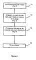
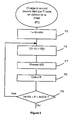
figures 4 à 7 représentent des organigrammes d'un mode préférentiel de réalisation du procédé selon l'invention.
- the
figure 1 schematically illustrates the variations, as a function of time, of the charging current I of a charged battery during the charging phase of the method according to the invention, as well as the corresponding variations of the voltage U, - the
figure 2 illustrates the variations, as a function of time, of the voltage U at the terminals of the battery charged by the method according to the invention, during the pulse current charging step, - the
figure 3 illustrates the voltage response of batteries to current pulses for different states of charge, - the
Figures 4 to 7 represent flowcharts of a preferred embodiment of the method according to the invention.
Dans le mode préféré de réalisation représenté sur les figures, une batterie présentant un état de charge inférieur à 100% est chargée dans une phase de charge qui sera décrite ci-après. Dans cette phase de charge, représentée sur la
Dans l'exemple illustré, l'application du courant constant à la valeur 13 constitue une étape de charge à courant constant. Cette étape est suivie, après le point A, d'une étape de charge par impulsions de courant aux amplitudes I1 et 12. Ces deux étapes constituent la phase de charge du procédé de gestion de charge ici décrit.In the example illustrated, the application of the constant current to the
Comme l'illustre la
Comme illustré à la
Pour déterminer, en temps réel, si l'état de charge de la batterie, pendant l'étape de charge par impulsions de courant, correspond à un état de pleine charge de la batterie, la valeur absolue de la pente P calculée ci-dessus à la fin de chaque période t1, t2 est comparée à un seuil prédéterminé de pleine charge, par exemple de 300mV/s, représentatif de la pleine charge de la batterie. Si la valeur absolue de la pente P est supérieure au seuil de pleine charge, l'étape de charge par impulsions de courant est interrompue.To determine, in real time, whether the state of charge of the battery, during the current pulse charging step, corresponds to a state of full charge of the battery, the absolute value of the slope P calculated above at the end of each period t1, t2 is compared with a predetermined threshold of full charge, for example 300mV / s, representative of the full charge of the battery. If the absolute value of the slope P is greater than the full load threshold, the step of charging by current pulses is interrupted.
En effet, comme représenté sur la
Pendant l'étape de charge à courant constant I3, c'est-à-dire avant le point A de la
Les
Comme illustré à la
Sur la
Lorsque l'étape F2 est interrompue par l'entrée de la valeur absolue de la pente P3 (ou plus généralement P) dans la plage correspondante, le régulateur contrôle, dans une étape F3, la charge de la batterie avec un courant pulsé. Le courant pulsé correspond à l'application d'impulsions rectangulaires périodiques de courant, ayant une première amplitude I1 pendant une première période t1, et une première amplitude 12 pendant une seconde période t2. I2 est avantageusement nulle mais elle peut aussi être non nulle. L'étape F3 est réalisée par le régulateur tant que la valeur absolue de la pente P1, P2 (ou plus généralement P) calculée à la fin de chaque période t1, t2 reste inférieure à un seuil prédéterminé de pleine charge, de préférence égal à 300mV/s. Ce seuil correspond physiquement, comme expliqué précédemment, à un état de charge SOC de la batterie de l'exemple égal à 100%.When the step F2 is interrupted by the entry of the absolute value of the slope P3 (or more generally P) in the corresponding range, the regulator controls, in a step F3, the charging of the battery with a pulsed current. The pulsed current corresponds to the application of periodic periodic pulses of current, having a first amplitude I1 during a first period t1, and a
Lorsque l'étape F3 est interrompue par l'égalité ou le dépassement de la valeur absolue de pente P1, P2 (ou plus généralement P), calculée à la fin de chaque période t1, t2, par rapport au seuil prédéterminé de 300mV/s, le régulateur passe à une étape F4 de fin de charge et la batterie est considérée comme pleinement chargée.When the step F3 is interrupted by the equality or the exceeding of the absolute value of slope P1, P2 (or more generally P), calculated at the end of each period t1, t2, with respect to the predetermined threshold of 300mV / s , the controller goes to a step F4 end of charge and the battery is considered fully charged.
Des exemples de réalisation des étapes F1 à F3 sont illustrés plus en détail respectivement sur les
Comme représenté à la ![]()
![]()
Lorsque, dans l'étape F9, le régulateur constate que la valeur absolue de la pente P est entrée dans la plage prédéterminée (sortie Oui de l'étape F9), l'étape F2 se termine et le régulateur passe alors à l'étape F3. Comme représenté à la
Dès que la batterie est soumise à la première impulsion de courant (laquelle, dans l'exemple illustré à la
Le régulateur passe ensuite à l'étape F12 dans laquelle la valeur de pente P est calculée en fin de période, ici t2 (P2 de la
Lorsque, dans l'étape F13, le régulateur constate que la valeur absolue de la pente P devient supérieure à 300mV/s (sortie Oui de l'étape F13), l'étape F3 se termine et le régulateur passe alors à l'étape F4 de fin de charge et la batterie est considérée comme pleinement chargée.When, in step F13, the controller finds that the absolute value of the slope P becomes greater than 300mV / s (Yes output of step F13), the step F3 ends and the regulator then proceeds to the step F4 end of charge and the battery is considered fully charged.
Dans une première étape F1 (
Comme illustré à la
Dès que la batterie est soumise à la première impulsion de courant de test, le régulateur passe à une étape F15 dans laquelle un nombre n est mis à zéro, puis à une étape F16 dans laquelle le régulateur réalise des mesures périodiques de la tension U(t) aux bornes de la batterie en cours de test. La tension U(t) évolue alors en réponse aux impulsions de courant de test d'amplitudes 14, 15 et le profil de U(t) est, de manière analogue à l'application d'impulsions de courant de charge d'amplitudes I1, I2, similaire à la courbe de la
Le régulateur passe ensuite à l'étape F17 dans laquelle la valeur de pente P, représentative de la variation de la tension en fonction du temps, est calculée en fin de période. La valeur absolue de la valeur de pente P calculée à l'étape F17 à la fin de la première période t3 ou t4 (suivant que le courant de test appliqué débute par une impulsion d'amplitude 14 ou bien une impulsion d'amplitude 15) est ensuite comparée, dans une étape F18, au seuil de pleine charge de 300mV/s. Si la valeur absolue de P est supérieure à 300mV/s, (sortie Oui de F18), le régulateur passe à une étape F19 correspondant à un état de charge de la batterie d'au moins 100%.The regulator then proceeds to step F17 in which the value of slope P, representative of the variation of the voltage as a function of time, is calculated at the end of the period. The absolute value of the slope value P calculated in step F17 at the end of the first period t3 or t4 (depending on whether the test current applied starts with an amplitude pulse 14 or an amplitude pulse 15) is then compared, in a step F18, to the full load threshold of 300mV / s. If the absolute value of P is greater than 300mV / s, (Yes output of F18), the controller goes to a step F19 corresponding to a state of charge of the battery of at least 100%.
Par contre, si la valeur absolue de P est inférieure à 300mV/s, (sortie Non de F18), le régulateur passe à une étape F21 dans laquelle le régulateur vérifie si le nombre n est égal à un nombre prédéterminé, par exemple 20. Une étape F20 peut éventuellement être intercalée entre les étapes F18 et F21, dans laquelle l'état de charge de la batterie testée est déterminé par comparaison de la valeur absolue de la pente P, calculée à l'étape 17, avec une table prédéterminée qui associe l'état de charge normal d'une batterie en fonction de la valeur absolue de la pente, en fin de période, de la réponse en tension à un courant pulsé. Cette détermination peut correspondre à des critères de décision d'opérations ultérieures à pratiquer sur la batterie, comme par exemple un boost de charge ou la réhabilitation de la batterie.On the other hand, if the absolute value of P is less than 300mV / s (output No of F18), the controller goes to a step F21 in which the regulator checks whether the number n is equal to a predetermined number, for example 20. A step F20 may optionally be interposed between steps F18 and F21, in which the state of charge of the tested battery is determined by comparing the absolute value of the slope P, calculated in step 17, with a predetermined table which associates the normal state of charge of a battery according to the absolute value of the slope, at the end of the period, of the voltage response to a pulsating current. This determination may correspond to decision criteria for subsequent operations to be practiced on the battery, such as for example a charge boost or the rehabilitation of the battery.
Lorsque, dans l'étape F21, le régulateur constate que le nombre n est inférieur à 20 (sortie Non de l'étape F21), il se reboucle sur l'étape F16 en pratiquant au préalable une étape F22 d'incrémentation du nombre n (n=n+1). Le régulateur continue d'appliquer le courant puisé de test à la batterie et assure de nouvelles mesures de la tension U(t) sur la période suivante, pour calculer une nouvelle valeur de P à la fin de cette période. La succession d'étapes F16 à F21 se répète à la fin de chaque période t3, t4 tant que le nombre n est inférieur à 20.When, in step F21, the controller finds that the number n is less than 20 (No output of step F21), it loops back to step F16 by first practicing a step F22 of incrementing the number n (n = n + 1). The controller continues to apply the pulsed test current to the battery and provides new measurements of the voltage U (t) over the next period, to calculate a new value of P at the end of this period. The succession of steps F16 to F21 is repeated at the end of each period t3, t4 as long as the number n is less than 20.
Lorsque, dans l'étape F21, le régulateur constate que le nombre n est égal à 20 (sortie Oui de l'étape F21), l'étape F1 se termine et le régulateur passe alors à l'étape F2 de charge à courant constant 13 et la phase de charge débute.When, in the step F21, the regulator finds that the number n is equal to 20 (Yes output of the step F21), the step F1 ends and the regulator then passes to the constant current
L'étape F1, qui comprend par exemple les étapes F14 à F22, constitue une phase d'estimation de l'état de charge de la batterie dont l'état de charge est inconnu et qui est éventuellement à charger. Le principe d'incrémentation du nombre n est un exemple de réalisation qui permet de s'assurer, qu'en pratique, la décision du passage à la phase de charge est prise après un petit nombre (20 dans l'exemple ci-dessus) d'impulsions de courant de test, suffisant pour s'affranchir de tout risque d'anomalie ou d'erreur. Pour des impulsions de test de 1 Hz de fréquence, le seuil 20 pour le nombre n correspond à une durée de 10s pour la phase d'estimation de l'état de charge de la batterie. Il est ainsi possible d'avoir une estimation rapide de l'état de charge d'une batterie.Step F1, which comprises, for example, steps F14 to F22, constitutes a phase for estimating the state of charge of the battery, the state of charge of which is unknown and which may possibly be charged. The principle of incrementing the number n is an exemplary embodiment which makes it possible to ascertain that, in practice, the decision to switch to the charging phase is taken after a small number (20 in the example above). test current pulses, sufficient to overcome any risk of abnormality or error. For test pulses of 1 Hz frequency, the
Lors de l'application pratique du procédé, pendant une période t1 à t4, la tension varie d'abord très rapidement avec une valeur absolue de pente P élevée, puis présente au moins une rupture de pente. La pente P (P1, P2, P3) à prendre en considération dans l'application du procédé de l'invention est celle mesurée à la fin de la période ou plus généralement dans la dernière partie de la période après la rupture de pente. La décision de la pente à utiliser, pour chaque période, peut se faire en fonction du temps, ou après la détection d'une rupture de pente (ce qui implique plusieurs mesures de la pente) ou simplement en prenant la dernière mesure effectuée durant la période. La dernière solution est la plus simple à mettre en oeuvre. D'autre part, on veillera à appliquer la même méthode sur toutes les périodes.During the practical application of the method, during a period t1 to t4, the voltage first varies very rapidly with an absolute value of high slope P, then has at least one slope break. The slope P (P1, P2, P3) to be taken into account in the application of the method of the invention is that measured at the end of the period or more generally in the last part of the period after the break of slope. The decision of the slope to be used, for each period, can be made as a function of time, or after the detection of a slope break (which involves several measurements of the slope) or simply by taking the last measurement made during the period. The last solution is the simplest to implement. On the other hand, we will take care to apply the same method on all periods.
Le procédé de gestion de charge décrit ci-dessus comporte ainsi une étape de charge par impulsions de courant, comportant la mesure de la tension U aux bornes de la batterie, la détermination de la pente P de la tension U à la fin de chaque période, la comparaison de la valeur absolue de la pente P de la tension U à un seuil prédéterminé de pleine charge et l'interruption de la charge lorsque la valeur absolue de la pente P est supérieure à ce seuil.The charge management method described above thus comprises a step of charging by current pulses, comprising the measurement of the voltage U at the terminals of the battery, the determination of the slope P of the voltage U at the end of each period. comparing the absolute value of the slope P of the voltage U with a predetermined threshold of full load and the interruption of the load when the absolute value of the slope P is greater than this threshold.
Ce procédé de gestion de charge, utilisant comme critère de fin de charge la valeur absolue de la pente P de la tension U aux bornes de la batterie lors de l'application d'un courant pulsé I, est, de préférence, utilisé avec une phase préalable d'estimation de l'état de charge utilisant le même critère. Il peut néanmoins être utilisé avec d'autres procédés d'estimation de l'état de charge utilisant d'autres critères.This charge management method, using as end of charge criterion the absolute value of the slope P of the voltage U at the terminals of the battery during the application of a pulsed current I, is preferably used with a previous stage of estimation of the state of charge using the same criterion. It can nevertheless be used with other state of charge estimation methods using other criteria.
Parallèlement, la phase d'estimation de la charge décrite ci-dessus, c'est-à-dire utilisant comme critère d'estimation de l'état de charge la valeur absolue de la pente de la réponse en tension à quelques impulsions de courant de test, peut être utilisée en association avec tout type de procédé de gestion de charge, qu'il utilise ou non le critère de fin de charge décrit ci dessus.At the same time, the load estimation phase described above, that is to say using, as criterion for estimating the state of charge, the absolute value of the slope of the voltage response to a few current pulses. test, may be used in combination with any type of charge management method, whether or not it uses the end of charge criterion described above.
Ainsi, le critère de fin de charge du procédé de gestion de charge et le critère de passage à la phase de charge dans une phase préalable d'estimation de charge appliquée à une batterie dont l'état de charge est inconnu, sont analogues. Dans tous les cas, ce critère comporte la comparaison, avec un seuil prédéterminé de pleine charge, de la valeur absolue de la pente de la tension aux bornes de la batterie, mesurée lors de l'application d'impulsions de courant.Thus, the end of charge criterion of the charge management method and the criterion of switching to the charge phase in a prior load estimation phase applied to a battery whose state of charge is unknown, are similar. In all cases, this criterion comprises comparing, with a predetermined threshold of full load, the absolute value of the slope of the voltage across the battery, measured during the application of current pulses.
Tandis que dans le document
Claims (6)
- A method for managing charging of a rechargeable battery, comprising at least one charging phase, said charging phase comprising at least;- a charging step by periodic rectangular current pulses (F3) alternately taking a first amplitude (I1) during a first period (t1) and a second amplitude (I2) during a second period (t2), the second amplitude being lower than the first,- periodic measurement of the voltage at the battery terminals,- calculation, from said voltage measurements, of a slope value (P) representative of the voltage variation versus time, characterized in that said charging phase comprises:- comparison of the absolute value of the slope (P) at the end of each period (t1, t2) with a predetermined full-charge threshold representative of full charge of the battery,- and interrupting said charging step by current pulses (F3) when said absolute value of the slope (P) is greater than or equal to said full-charge threshold.
- The method according to claim 1, characterized in that the full-charge threshold is equal to 300mV/s.
- The method according to one of claims 1 and 2, characterized in that the charging phase comprises a charging step at constant current (F2), before the charging step by current pulses (F3), the absolute value of the voltage slope (P), measured periodically during said charging step at constant current (F2), being compared with a predetermined range, and switching to the charging step by current pulses (F3) taking place when the absolute value of the slope (P) enters said predetermined range.
- The method according to claim 3, characterized in that the predetermined range is comprised between 1 mV/s and 6mV/s.
- The method according to any ane of claims 1 to 4, characterized in that before the charging phase, the method comprises a prior phase of estimating the state of charge of the battery, which comprises:- application of a few periodic rectangular test current pulses alternately taking the first amplitude (I4) during the first period (t3) and the second amplitude (I5) during the second period (t4),- periodic measurement of the voltage at the battery terminals,- calculation, from said voltage measurements, of the voltage slope value (P),- comparison of the absolute value of the slope (P) with said full-charge threshold,- and switching to charging phase when said absolute value of the slope (P) is lower than said full-charge threshold.
- A method for managing charging of a rechargeable battery, comprising at least one charging phase and a prior phase of estimating the state of charge of the battery, the prior phase of estimating the state of charge comprising :- application of a few periodic rectangular test current pulses alternately taking the first amplitude (I4) during a first period (t3) and the second amplitude (15) during a second period (t4),- periodic measurement of the voltage at the battery terminals,- calculation, from said voltage measurements, of the voltage slope value (P) representative of the variation of the voltage versus time,- comparison of the absolute value of the slope (P) with a predetermined full-charge threshold,- and switching to charging phase when said absolute value of the slope (P) is lower than said full-charge threshold.
Applications Claiming Priority (2)
| Application Number | Priority Date | Filing Date | Title |
|---|---|---|---|
| FR0609668A FR2908243B1 (en) | 2006-11-06 | 2006-11-06 | METHOD FOR MANAGING THE CHARGE OF A RECHARGEABLE BATTERY |
| PCT/FR2007/001821 WO2008065273A2 (en) | 2006-11-06 | 2007-11-05 | Method for managing charging of a rechargeable battery |
Publications (2)
| Publication Number | Publication Date |
|---|---|
| EP2087574A2 EP2087574A2 (en) | 2009-08-12 |
| EP2087574B1 true EP2087574B1 (en) | 2015-01-07 |
Family
ID=38519832
Family Applications (1)
| Application Number | Title | Priority Date | Filing Date |
|---|---|---|---|
| EP07870241.2A Not-in-force EP2087574B1 (en) | 2006-11-06 | 2007-11-05 | Method for managing charging of a rechargeable battery |
Country Status (5)
| Country | Link |
|---|---|
| US (1) | US8093866B2 (en) |
| EP (1) | EP2087574B1 (en) |
| JP (1) | JP2010508807A (en) |
| FR (1) | FR2908243B1 (en) |
| WO (1) | WO2008065273A2 (en) |
Families Citing this family (29)
| Publication number | Priority date | Publication date | Assignee | Title |
|---|---|---|---|---|
| FR2936110B1 (en) | 2008-09-16 | 2010-10-01 | Commissariat Energie Atomique | AUTONOMOUS SYSTEM COMPRISING A BATTERY AND A SUPERCAPACITY AND A CHARGING METHOD. |
| RU2437190C2 (en) * | 2009-08-07 | 2011-12-20 | Геннадий Дмитриевич Платонов | Storage battery restoration method and device for its implementation |
| JP2011109833A (en) * | 2009-11-18 | 2011-06-02 | Sony Corp | Method and device for charging secondary battery |
| CN102292863B (en) * | 2009-12-14 | 2014-05-07 | 松下电器产业株式会社 | Method for determining completion of charging and discharging of lithium-ion secondary battery, charge control circuit, discharge control circuit, and power supply |
| JP5506498B2 (en) * | 2010-03-30 | 2014-05-28 | パナソニック株式会社 | Secondary battery charging device and charging method |
| US11397216B2 (en) | 2010-05-21 | 2022-07-26 | Qnovo Inc. | Battery adaptive charging using a battery model |
| US9142994B2 (en) | 2012-09-25 | 2015-09-22 | Qnovo, Inc. | Method and circuitry to adaptively charge a battery/cell |
| US10067198B2 (en) | 2010-05-21 | 2018-09-04 | Qnovo Inc. | Method and circuitry to adaptively charge a battery/cell using the state of health thereof |
| US8791669B2 (en) | 2010-06-24 | 2014-07-29 | Qnovo Inc. | Method and circuitry to calculate the state of charge of a battery/cell |
| US8638070B2 (en) | 2010-05-21 | 2014-01-28 | Qnovo Inc. | Method and circuitry to adaptively charge a battery/cell |
| US11397215B2 (en) | 2010-05-21 | 2022-07-26 | Qnovo Inc. | Battery adaptive charging using battery physical phenomena |
| US10389156B2 (en) | 2010-05-21 | 2019-08-20 | Qnovo Inc. | Method and circuitry to adaptively charge a battery/cell |
| US11791647B2 (en) | 2010-05-21 | 2023-10-17 | Qnovo Inc. | Method and circuitry to adaptively charge a battery/cell |
| US8970178B2 (en) | 2010-06-24 | 2015-03-03 | Qnovo Inc. | Method and circuitry to calculate the state of charge of a battery/cell |
| US8872518B2 (en) * | 2010-06-25 | 2014-10-28 | Atieva, Inc. | Determining the state of-charge of batteries via selective sampling of extrapolated open circuit voltage |
| US9063018B1 (en) | 2012-10-22 | 2015-06-23 | Qnovo Inc. | Method and circuitry to determine temperature and/or state of health of a battery/cell |
| DE102012024378A1 (en) * | 2012-12-12 | 2014-06-12 | Leopold Kostal Gmbh & Co. Kg | Battery management system for rechargeable battery with battery cell, has control unit, battery charger connected with external power source, current sensor and voltage sensors, where battery charger stores charge current in battery |
| US9461492B1 (en) | 2013-04-19 | 2016-10-04 | Qnovo Inc. | Method and circuitry to adaptively charge a battery/cell using a charge-time parameter |
| US20140361752A1 (en) * | 2013-06-07 | 2014-12-11 | International Battery Corporation | Battery charging method and apparatus |
| US10574079B1 (en) | 2014-06-20 | 2020-02-25 | Qnovo Inc. | Wireless charging techniques and circuitry for a battery |
| DE102014012542A1 (en) | 2014-08-28 | 2016-03-03 | Deutsches Zentrum für Luft- und Raumfahrt e.V. (DLR) | Method for determining an operating state of a battery system |
| FR3035550B1 (en) | 2015-04-27 | 2019-05-03 | Commissariat A L'energie Atomique Et Aux Energies Alternatives | METHOD FOR ELECTRICALLY CHARGING A BATTERY WITH AN INTERMITTENT ENERGY SOURCE AND CORRESPONDING CHARGE CONTROL DEVICE |
| US11063458B1 (en) * | 2015-08-26 | 2021-07-13 | Google Llc | Systems and methods for dynamic pulse charging |
| JP6573120B2 (en) * | 2016-01-26 | 2019-09-11 | 株式会社Gsユアサ | State estimation device, power storage element module, vehicle, and state estimation method |
| KR102441469B1 (en) * | 2017-11-13 | 2022-09-06 | 주식회사 엘지에너지솔루션 | Battery charging method and battery charging apparatus |
| DE102018209461A1 (en) | 2018-06-13 | 2019-12-19 | Bayerische Motoren Werke Aktiengesellschaft | Method for impedance-controlled rapid charging, control unit for a charging system, energy storage and working device |
| DE102018211265A1 (en) * | 2018-07-09 | 2020-01-09 | Volkswagen Aktiengesellschaft | Method of charging a battery and control unit |
| DE102018211264A1 (en) * | 2018-07-09 | 2020-01-09 | Volkswagen Aktiengesellschaft | Method of charging a battery and control unit |
| CN112731155B (en) * | 2020-12-08 | 2022-02-22 | 浙江南都电源动力股份有限公司 | Method for judging charge-discharge state of lithium iron phosphate battery |
Family Cites Families (16)
| Publication number | Priority date | Publication date | Assignee | Title |
|---|---|---|---|---|
| JPS5425437A (en) * | 1977-07-28 | 1979-02-26 | Suwa Seikosha Kk | Method of charging |
| JPS54119637A (en) * | 1978-03-08 | 1979-09-17 | Sansha Electric Mfg Co Ltd | Method of detecting completion of charge for storage battery |
| US5686815A (en) * | 1991-02-14 | 1997-11-11 | Chartec Laboratories A/S | Method and apparatus for controlling the charging of a rechargeable battery to ensure that full charge is achieved without damaging the battery |
| JPH09233725A (en) * | 1996-02-20 | 1997-09-05 | Brother Ind Ltd | Quick charge circuit |
| JPH09308123A (en) * | 1996-05-20 | 1997-11-28 | Toyota Motor Corp | Charger |
| US5900718A (en) * | 1996-08-16 | 1999-05-04 | Total Battery Management, | Battery charger and method of charging batteries |
| JP3506916B2 (en) * | 1998-07-03 | 2004-03-15 | 株式会社マキタ | Charging device |
| JP3941324B2 (en) * | 2000-03-23 | 2007-07-04 | 新神戸電機株式会社 | Battery charge state estimation method and battery charge state control method |
| FR2813124B1 (en) * | 2000-08-17 | 2003-01-17 | Oldham France Sa | METHOD FOR TESTING A LEAD BATTERY FOR ITS CHARGE UNDER OPTIMAL CONDITIONS |
| US6841974B2 (en) * | 2001-03-13 | 2005-01-11 | Hdm Systems Corporation | Battery charging method |
| WO2003030331A1 (en) * | 2001-10-03 | 2003-04-10 | Trojan Battery Company | System and method for battery charging |
| US6791300B2 (en) * | 2002-02-28 | 2004-09-14 | Black & Decker Inc. | Battery charger and charging method |
| KR100542215B1 (en) * | 2003-12-23 | 2006-01-10 | 삼성에스디아이 주식회사 | Charging method of rechargeable batteries and device therefor |
| WO2005101042A1 (en) | 2004-04-06 | 2005-10-27 | Cobasys, Llc | Battery state of charge estimator |
| US7446509B2 (en) | 2004-05-08 | 2008-11-04 | Gem Power, Llc | Intelligent battery charging system |
| FR2870391B1 (en) | 2004-05-13 | 2007-09-21 | Commissariat Energie Atomique | METHOD FOR CHARGING A BATTERY |
-
2006
- 2006-11-06 FR FR0609668A patent/FR2908243B1/en not_active Expired - Fee Related
-
2007
- 2007-11-05 EP EP07870241.2A patent/EP2087574B1/en not_active Not-in-force
- 2007-11-05 JP JP2009535769A patent/JP2010508807A/en active Pending
- 2007-11-05 WO PCT/FR2007/001821 patent/WO2008065273A2/en active Application Filing
- 2007-11-05 US US12/312,027 patent/US8093866B2/en not_active Expired - Fee Related
Also Published As
| Publication number | Publication date |
|---|---|
| WO2008065273A3 (en) | 2008-07-17 |
| JP2010508807A (en) | 2010-03-18 |
| WO2008065273A2 (en) | 2008-06-05 |
| US20100060240A1 (en) | 2010-03-11 |
| EP2087574A2 (en) | 2009-08-12 |
| US8093866B2 (en) | 2012-01-10 |
| FR2908243A1 (en) | 2008-05-09 |
| FR2908243B1 (en) | 2009-02-13 |
Similar Documents
| Publication | Publication Date | Title |
|---|---|---|
| EP2087574B1 (en) | Method for managing charging of a rechargeable battery | |
| JP5160220B2 (en) | How to manage a pool of rechargeable batteries | |
| EP2634591B1 (en) | Method and system for estimating the charge level of a lithium electrochemical element including a lithium phosphate positive electrode | |
| EP3028054B1 (en) | Estimation of the state of deterioration of an electric battery | |
| EP2122379B1 (en) | Method for determining the discharge end threshold of a rechargeable battery | |
| EP1685622B1 (en) | Equilibrated charging method for a lithium-ion or lithium-polymer battery | |
| FR2813124A1 (en) | METHOD FOR TESTING A LEAD BATTERY FOR ITS CHARGE UNDER OPTIMAL CONDITIONS | |
| EP3443370B1 (en) | Method for determining the value of parameters relating to the state of an accumulator of a battery, battery and electronic battery management system | |
| EP2016434A2 (en) | Method for managing an assembly of rechargeable batteries using a charging whiplash effect | |
| EP3258282A1 (en) | Method and device for assessing an indicator of the state of health of a cell of a lithium battery | |
| FR2963109A1 (en) | METHOD FOR DETERMINING A PARAMETER OF AT LEAST ONE BATTERY ACCUMULATOR | |
| FR3065292B1 (en) | METHOD OF MANAGING A BATTERY BASED ON ITS HEALTH CONDITION | |
| EP0498715A1 (en) | Process for optimizing the charge of an accumulator battery and apparatus for carrying out the process | |
| EP3096974A1 (en) | Method for managing a state of charge of a battery | |
| FR3041765A1 (en) | METHOD FOR ESTIMATING A HEALTH STATUS INDICATOR OF A LITHIUM BATTERY AND ASSOCIATED ESTIMATION DEVICE | |
| EP2001074B1 (en) | System and method to determine the loss in capacity and energy of a battery determining the output capacity of a battery | |
| EP3324197B1 (en) | Method for determining the state of health of a battery cell | |
| FR2822297A1 (en) | METHOD FOR CONTROLLING THE DISCHARGE OF A BATTERY OF SECONDARY ELECTROCHEMICAL GENERATORS | |
| FR3001086A1 (en) | MANAGING THE CHARGE OF A BATTERY. | |
| EP3235048B1 (en) | Pulsed charging method for lithium ion batteries and apparatus therefor | |
| FR3009754A1 (en) | DIAGNOSIS OF THE INTERNAL RESISTANCE OF AN ELECTRIC BATTERY | |
| EP2924454A1 (en) | Method for estimating and resetting of the state of charge of a battery cell | |
| EP4101047B1 (en) | Method of pulse charging with variable amplitude step | |
| FR3045218A1 (en) | DETERMINATION OF PARAMETERS OF A DYNAMIC MODEL FOR AN ELECTROCHEMICAL BATTERY CELL | |
| FR3035550A1 (en) | METHOD FOR ELECTRICALLY CHARGING A BATTERY WITH AN INTERMITTENT ENERGY SOURCE AND CORRESPONDING CHARGE CONTROL DEVICE |
Legal Events
| Date | Code | Title | Description |
|---|---|---|---|
| PUAI | Public reference made under article 153(3) epc to a published international application that has entered the european phase |
Free format text: ORIGINAL CODE: 0009012 |
|
| 17P | Request for examination filed |
Effective date: 20090423 |
|
| AK | Designated contracting states |
Kind code of ref document: A2 Designated state(s): AT BE BG CH CY CZ DE DK EE ES FI FR GB GR HU IE IS IT LI LT LU LV MC MT NL PL PT RO SE SI SK TR |
|
| RIN1 | Information on inventor provided before grant (corrected) |
Inventor name: LEMAIRE, ELISABETH Inventor name: KAROUI, FATHIA Inventor name: LEFROU, CHRISTINE |
|
| 17Q | First examination report despatched |
Effective date: 20090904 |
|
| DAX | Request for extension of the european patent (deleted) | ||
| RAP1 | Party data changed (applicant data changed or rights of an application transferred) |
Owner name: COMMISSARIAT A L'ENERGIE ATOMIQUE ET AUX ENERGIES |
|
| RIC1 | Information provided on ipc code assigned before grant |
Ipc: H02J 7/00 20060101AFI20140204BHEP Ipc: H01M 10/44 20060101ALI20140204BHEP |
|
| GRAP | Despatch of communication of intention to grant a patent |
Free format text: ORIGINAL CODE: EPIDOSNIGR1 |
|
| INTG | Intention to grant announced |
Effective date: 20141006 |
|
| GRAS | Grant fee paid |
Free format text: ORIGINAL CODE: EPIDOSNIGR3 |
|
| GRAA | (expected) grant |
Free format text: ORIGINAL CODE: 0009210 |
|
| AK | Designated contracting states |
Kind code of ref document: B1 Designated state(s): AT BE BG CH CY CZ DE DK EE ES FI FR GB GR HU IE IS IT LI LT LU LV MC MT NL PL PT RO SE SI SK TR |
|
| REG | Reference to a national code |
Ref country code: GB Ref legal event code: FG4D Free format text: NOT ENGLISH |
|
| REG | Reference to a national code |
Ref country code: CH Ref legal event code: EP |
|
| REG | Reference to a national code |
Ref country code: IE Ref legal event code: FG4D Free format text: LANGUAGE OF EP DOCUMENT: FRENCH |
|
| REG | Reference to a national code |
Ref country code: AT Ref legal event code: REF Ref document number: 706319 Country of ref document: AT Kind code of ref document: T Effective date: 20150215 |
|
| REG | Reference to a national code |
Ref country code: DE Ref legal event code: R096 Ref document number: 602007040023 Country of ref document: DE Effective date: 20150219 |
|
| REG | Reference to a national code |
Ref country code: NL Ref legal event code: VDEP Effective date: 20150107 |
|
| REG | Reference to a national code |
Ref country code: AT Ref legal event code: MK05 Ref document number: 706319 Country of ref document: AT Kind code of ref document: T Effective date: 20150107 |
|
| REG | Reference to a national code |
Ref country code: LT Ref legal event code: MG4D |
|
| PG25 | Lapsed in a contracting state [announced via postgrant information from national office to epo] |
Ref country code: FI Free format text: LAPSE BECAUSE OF FAILURE TO SUBMIT A TRANSLATION OF THE DESCRIPTION OR TO PAY THE FEE WITHIN THE PRESCRIBED TIME-LIMIT Effective date: 20150107 Ref country code: LT Free format text: LAPSE BECAUSE OF FAILURE TO SUBMIT A TRANSLATION OF THE DESCRIPTION OR TO PAY THE FEE WITHIN THE PRESCRIBED TIME-LIMIT Effective date: 20150107 Ref country code: SE Free format text: LAPSE BECAUSE OF FAILURE TO SUBMIT A TRANSLATION OF THE DESCRIPTION OR TO PAY THE FEE WITHIN THE PRESCRIBED TIME-LIMIT Effective date: 20150107 Ref country code: BG Free format text: LAPSE BECAUSE OF FAILURE TO SUBMIT A TRANSLATION OF THE DESCRIPTION OR TO PAY THE FEE WITHIN THE PRESCRIBED TIME-LIMIT Effective date: 20150407 Ref country code: ES Free format text: LAPSE BECAUSE OF FAILURE TO SUBMIT A TRANSLATION OF THE DESCRIPTION OR TO PAY THE FEE WITHIN THE PRESCRIBED TIME-LIMIT Effective date: 20150107 |
|
| PG25 | Lapsed in a contracting state [announced via postgrant information from national office to epo] |
Ref country code: IS Free format text: LAPSE BECAUSE OF FAILURE TO SUBMIT A TRANSLATION OF THE DESCRIPTION OR TO PAY THE FEE WITHIN THE PRESCRIBED TIME-LIMIT Effective date: 20150507 Ref country code: NL Free format text: LAPSE BECAUSE OF FAILURE TO SUBMIT A TRANSLATION OF THE DESCRIPTION OR TO PAY THE FEE WITHIN THE PRESCRIBED TIME-LIMIT Effective date: 20150107 Ref country code: LV Free format text: LAPSE BECAUSE OF FAILURE TO SUBMIT A TRANSLATION OF THE DESCRIPTION OR TO PAY THE FEE WITHIN THE PRESCRIBED TIME-LIMIT Effective date: 20150107 Ref country code: AT Free format text: LAPSE BECAUSE OF FAILURE TO SUBMIT A TRANSLATION OF THE DESCRIPTION OR TO PAY THE FEE WITHIN THE PRESCRIBED TIME-LIMIT Effective date: 20150107 Ref country code: PL Free format text: LAPSE BECAUSE OF FAILURE TO SUBMIT A TRANSLATION OF THE DESCRIPTION OR TO PAY THE FEE WITHIN THE PRESCRIBED TIME-LIMIT Effective date: 20150107 Ref country code: GR Free format text: LAPSE BECAUSE OF FAILURE TO SUBMIT A TRANSLATION OF THE DESCRIPTION OR TO PAY THE FEE WITHIN THE PRESCRIBED TIME-LIMIT Effective date: 20150408 |
|
| REG | Reference to a national code |
Ref country code: DE Ref legal event code: R097 Ref document number: 602007040023 Country of ref document: DE |
|
| PG25 | Lapsed in a contracting state [announced via postgrant information from national office to epo] |
Ref country code: CZ Free format text: LAPSE BECAUSE OF FAILURE TO SUBMIT A TRANSLATION OF THE DESCRIPTION OR TO PAY THE FEE WITHIN THE PRESCRIBED TIME-LIMIT Effective date: 20150107 Ref country code: SK Free format text: LAPSE BECAUSE OF FAILURE TO SUBMIT A TRANSLATION OF THE DESCRIPTION OR TO PAY THE FEE WITHIN THE PRESCRIBED TIME-LIMIT Effective date: 20150107 Ref country code: EE Free format text: LAPSE BECAUSE OF FAILURE TO SUBMIT A TRANSLATION OF THE DESCRIPTION OR TO PAY THE FEE WITHIN THE PRESCRIBED TIME-LIMIT Effective date: 20150107 Ref country code: DK Free format text: LAPSE BECAUSE OF FAILURE TO SUBMIT A TRANSLATION OF THE DESCRIPTION OR TO PAY THE FEE WITHIN THE PRESCRIBED TIME-LIMIT Effective date: 20150107 Ref country code: RO Free format text: LAPSE BECAUSE OF FAILURE TO SUBMIT A TRANSLATION OF THE DESCRIPTION OR TO PAY THE FEE WITHIN THE PRESCRIBED TIME-LIMIT Effective date: 20150107 |
|
| PLBE | No opposition filed within time limit |
Free format text: ORIGINAL CODE: 0009261 |
|
| STAA | Information on the status of an ep patent application or granted ep patent |
Free format text: STATUS: NO OPPOSITION FILED WITHIN TIME LIMIT |
|
| REG | Reference to a national code |
Ref country code: FR Ref legal event code: PLFP Year of fee payment: 9 |
|
| 26N | No opposition filed |
Effective date: 20151008 |
|
| PG25 | Lapsed in a contracting state [announced via postgrant information from national office to epo] |
Ref country code: IT Free format text: LAPSE BECAUSE OF FAILURE TO SUBMIT A TRANSLATION OF THE DESCRIPTION OR TO PAY THE FEE WITHIN THE PRESCRIBED TIME-LIMIT Effective date: 20150107 |
|
| PG25 | Lapsed in a contracting state [announced via postgrant information from national office to epo] |
Ref country code: SI Free format text: LAPSE BECAUSE OF FAILURE TO SUBMIT A TRANSLATION OF THE DESCRIPTION OR TO PAY THE FEE WITHIN THE PRESCRIBED TIME-LIMIT Effective date: 20150107 |
|
| PG25 | Lapsed in a contracting state [announced via postgrant information from national office to epo] |
Ref country code: MC Free format text: LAPSE BECAUSE OF FAILURE TO SUBMIT A TRANSLATION OF THE DESCRIPTION OR TO PAY THE FEE WITHIN THE PRESCRIBED TIME-LIMIT Effective date: 20150107 Ref country code: LU Free format text: LAPSE BECAUSE OF FAILURE TO SUBMIT A TRANSLATION OF THE DESCRIPTION OR TO PAY THE FEE WITHIN THE PRESCRIBED TIME-LIMIT Effective date: 20151105 |
|
| REG | Reference to a national code |
Ref country code: CH Ref legal event code: PL |
|
| PG25 | Lapsed in a contracting state [announced via postgrant information from national office to epo] |
Ref country code: LI Free format text: LAPSE BECAUSE OF NON-PAYMENT OF DUE FEES Effective date: 20151130 Ref country code: CH Free format text: LAPSE BECAUSE OF NON-PAYMENT OF DUE FEES Effective date: 20151130 |
|
| REG | Reference to a national code |
Ref country code: IE Ref legal event code: MM4A |
|
| PG25 | Lapsed in a contracting state [announced via postgrant information from national office to epo] |
Ref country code: IE Free format text: LAPSE BECAUSE OF NON-PAYMENT OF DUE FEES Effective date: 20151105 |
|
| REG | Reference to a national code |
Ref country code: FR Ref legal event code: PLFP Year of fee payment: 10 |
|
| PG25 | Lapsed in a contracting state [announced via postgrant information from national office to epo] |
Ref country code: HU Free format text: LAPSE BECAUSE OF FAILURE TO SUBMIT A TRANSLATION OF THE DESCRIPTION OR TO PAY THE FEE WITHIN THE PRESCRIBED TIME-LIMIT; INVALID AB INITIO Effective date: 20071105 |
|
| PG25 | Lapsed in a contracting state [announced via postgrant information from national office to epo] |
Ref country code: CY Free format text: LAPSE BECAUSE OF FAILURE TO SUBMIT A TRANSLATION OF THE DESCRIPTION OR TO PAY THE FEE WITHIN THE PRESCRIBED TIME-LIMIT Effective date: 20150107 |
|
| PG25 | Lapsed in a contracting state [announced via postgrant information from national office to epo] |
Ref country code: BE Free format text: LAPSE BECAUSE OF NON-PAYMENT OF DUE FEES Effective date: 20151130 |
|
| PG25 | Lapsed in a contracting state [announced via postgrant information from national office to epo] |
Ref country code: TR Free format text: LAPSE BECAUSE OF FAILURE TO SUBMIT A TRANSLATION OF THE DESCRIPTION OR TO PAY THE FEE WITHIN THE PRESCRIBED TIME-LIMIT Effective date: 20150107 Ref country code: MT Free format text: LAPSE BECAUSE OF FAILURE TO SUBMIT A TRANSLATION OF THE DESCRIPTION OR TO PAY THE FEE WITHIN THE PRESCRIBED TIME-LIMIT Effective date: 20150107 |
|
| REG | Reference to a national code |
Ref country code: FR Ref legal event code: PLFP Year of fee payment: 11 |
|
| PG25 | Lapsed in a contracting state [announced via postgrant information from national office to epo] |
Ref country code: PT Free format text: LAPSE BECAUSE OF FAILURE TO SUBMIT A TRANSLATION OF THE DESCRIPTION OR TO PAY THE FEE WITHIN THE PRESCRIBED TIME-LIMIT Effective date: 20150107 |
|
| PGFP | Annual fee paid to national office [announced via postgrant information from national office to epo] |
Ref country code: DE Payment date: 20181112 Year of fee payment: 12 |
|
| PGFP | Annual fee paid to national office [announced via postgrant information from national office to epo] |
Ref country code: FR Payment date: 20181129 Year of fee payment: 12 Ref country code: GB Payment date: 20181116 Year of fee payment: 12 |
|
| REG | Reference to a national code |
Ref country code: DE Ref legal event code: R119 Ref document number: 602007040023 Country of ref document: DE |
|
| GBPC | Gb: european patent ceased through non-payment of renewal fee |
Effective date: 20191105 |
|
| PG25 | Lapsed in a contracting state [announced via postgrant information from national office to epo] |
Ref country code: DE Free format text: LAPSE BECAUSE OF NON-PAYMENT OF DUE FEES Effective date: 20200603 Ref country code: GB Free format text: LAPSE BECAUSE OF NON-PAYMENT OF DUE FEES Effective date: 20191105 Ref country code: FR Free format text: LAPSE BECAUSE OF NON-PAYMENT OF DUE FEES Effective date: 20191130 |