EP3220449A1 - Method for welding electrode leads of secondary battery module, and compact secondary battery module for which the method has been used - Google Patents
Method for welding electrode leads of secondary battery module, and compact secondary battery module for which the method has been used Download PDFInfo
- Publication number
- EP3220449A1 EP3220449A1 EP15873696.7A EP15873696A EP3220449A1 EP 3220449 A1 EP3220449 A1 EP 3220449A1 EP 15873696 A EP15873696 A EP 15873696A EP 3220449 A1 EP3220449 A1 EP 3220449A1
- Authority
- EP
- European Patent Office
- Prior art keywords
- lead
- secondary battery
- battery module
- module according
- compact secondary
- Prior art date
- Legal status (The legal status is an assumption and is not a legal conclusion. Google has not performed a legal analysis and makes no representation as to the accuracy of the status listed.)
- Granted
Links
Images



Classifications
-
- B—PERFORMING OPERATIONS; TRANSPORTING
- B23—MACHINE TOOLS; METAL-WORKING NOT OTHERWISE PROVIDED FOR
- B23K—SOLDERING OR UNSOLDERING; WELDING; CLADDING OR PLATING BY SOLDERING OR WELDING; CUTTING BY APPLYING HEAT LOCALLY, e.g. FLAME CUTTING; WORKING BY LASER BEAM
- B23K26/00—Working by laser beam, e.g. welding, cutting or boring
- B23K26/20—Bonding
- B23K26/21—Bonding by welding
-
- H—ELECTRICITY
- H01—ELECTRIC ELEMENTS
- H01M—PROCESSES OR MEANS, e.g. BATTERIES, FOR THE DIRECT CONVERSION OF CHEMICAL ENERGY INTO ELECTRICAL ENERGY
- H01M10/00—Secondary cells; Manufacture thereof
- H01M10/42—Methods or arrangements for servicing or maintenance of secondary cells or secondary half-cells
- H01M10/46—Accumulators structurally combined with charging apparatus
-
- H—ELECTRICITY
- H01—ELECTRIC ELEMENTS
- H01M—PROCESSES OR MEANS, e.g. BATTERIES, FOR THE DIRECT CONVERSION OF CHEMICAL ENERGY INTO ELECTRICAL ENERGY
- H01M50/00—Constructional details or processes of manufacture of the non-active parts of electrochemical cells other than fuel cells, e.g. hybrid cells
- H01M50/50—Current conducting connections for cells or batteries
- H01M50/502—Interconnectors for connecting terminals of adjacent batteries; Interconnectors for connecting cells outside a battery casing
- H01M50/514—Methods for interconnecting adjacent batteries or cells
- H01M50/516—Methods for interconnecting adjacent batteries or cells by welding, soldering or brazing
-
- B—PERFORMING OPERATIONS; TRANSPORTING
- B23—MACHINE TOOLS; METAL-WORKING NOT OTHERWISE PROVIDED FOR
- B23K—SOLDERING OR UNSOLDERING; WELDING; CLADDING OR PLATING BY SOLDERING OR WELDING; CUTTING BY APPLYING HEAT LOCALLY, e.g. FLAME CUTTING; WORKING BY LASER BEAM
- B23K26/00—Working by laser beam, e.g. welding, cutting or boring
- B23K26/20—Bonding
- B23K26/32—Bonding taking account of the properties of the material involved
- B23K26/323—Bonding taking account of the properties of the material involved involving parts made of dissimilar metallic material
-
- H—ELECTRICITY
- H01—ELECTRIC ELEMENTS
- H01M—PROCESSES OR MEANS, e.g. BATTERIES, FOR THE DIRECT CONVERSION OF CHEMICAL ENERGY INTO ELECTRICAL ENERGY
- H01M10/00—Secondary cells; Manufacture thereof
- H01M10/05—Accumulators with non-aqueous electrolyte
- H01M10/052—Li-accumulators
- H01M10/0525—Rocking-chair batteries, i.e. batteries with lithium insertion or intercalation in both electrodes; Lithium-ion batteries
-
- H—ELECTRICITY
- H01—ELECTRIC ELEMENTS
- H01M—PROCESSES OR MEANS, e.g. BATTERIES, FOR THE DIRECT CONVERSION OF CHEMICAL ENERGY INTO ELECTRICAL ENERGY
- H01M10/00—Secondary cells; Manufacture thereof
- H01M10/42—Methods or arrangements for servicing or maintenance of secondary cells or secondary half-cells
- H01M10/425—Structural combination with electronic components, e.g. electronic circuits integrated to the outside of the casing
-
- H—ELECTRICITY
- H01—ELECTRIC ELEMENTS
- H01M—PROCESSES OR MEANS, e.g. BATTERIES, FOR THE DIRECT CONVERSION OF CHEMICAL ENERGY INTO ELECTRICAL ENERGY
- H01M10/00—Secondary cells; Manufacture thereof
- H01M10/42—Methods or arrangements for servicing or maintenance of secondary cells or secondary half-cells
- H01M10/48—Accumulators combined with arrangements for measuring, testing or indicating the condition of cells, e.g. the level or density of the electrolyte
-
- H—ELECTRICITY
- H01—ELECTRIC ELEMENTS
- H01M—PROCESSES OR MEANS, e.g. BATTERIES, FOR THE DIRECT CONVERSION OF CHEMICAL ENERGY INTO ELECTRICAL ENERGY
- H01M10/00—Secondary cells; Manufacture thereof
- H01M10/42—Methods or arrangements for servicing or maintenance of secondary cells or secondary half-cells
- H01M10/48—Accumulators combined with arrangements for measuring, testing or indicating the condition of cells, e.g. the level or density of the electrolyte
- H01M10/482—Accumulators combined with arrangements for measuring, testing or indicating the condition of cells, e.g. the level or density of the electrolyte for several batteries or cells simultaneously or sequentially
-
- H—ELECTRICITY
- H01—ELECTRIC ELEMENTS
- H01M—PROCESSES OR MEANS, e.g. BATTERIES, FOR THE DIRECT CONVERSION OF CHEMICAL ENERGY INTO ELECTRICAL ENERGY
- H01M10/00—Secondary cells; Manufacture thereof
- H01M10/42—Methods or arrangements for servicing or maintenance of secondary cells or secondary half-cells
- H01M10/48—Accumulators combined with arrangements for measuring, testing or indicating the condition of cells, e.g. the level or density of the electrolyte
- H01M10/486—Accumulators combined with arrangements for measuring, testing or indicating the condition of cells, e.g. the level or density of the electrolyte for measuring temperature
-
- H—ELECTRICITY
- H01—ELECTRIC ELEMENTS
- H01M—PROCESSES OR MEANS, e.g. BATTERIES, FOR THE DIRECT CONVERSION OF CHEMICAL ENERGY INTO ELECTRICAL ENERGY
- H01M50/00—Constructional details or processes of manufacture of the non-active parts of electrochemical cells other than fuel cells, e.g. hybrid cells
- H01M50/20—Mountings; Secondary casings or frames; Racks, modules or packs; Suspension devices; Shock absorbers; Transport or carrying devices; Holders
- H01M50/204—Racks, modules or packs for multiple batteries or multiple cells
-
- H—ELECTRICITY
- H01—ELECTRIC ELEMENTS
- H01M—PROCESSES OR MEANS, e.g. BATTERIES, FOR THE DIRECT CONVERSION OF CHEMICAL ENERGY INTO ELECTRICAL ENERGY
- H01M50/00—Constructional details or processes of manufacture of the non-active parts of electrochemical cells other than fuel cells, e.g. hybrid cells
- H01M50/20—Mountings; Secondary casings or frames; Racks, modules or packs; Suspension devices; Shock absorbers; Transport or carrying devices; Holders
- H01M50/204—Racks, modules or packs for multiple batteries or multiple cells
- H01M50/207—Racks, modules or packs for multiple batteries or multiple cells characterised by their shape
- H01M50/209—Racks, modules or packs for multiple batteries or multiple cells characterised by their shape adapted for prismatic or rectangular cells
-
- H—ELECTRICITY
- H01—ELECTRIC ELEMENTS
- H01M—PROCESSES OR MEANS, e.g. BATTERIES, FOR THE DIRECT CONVERSION OF CHEMICAL ENERGY INTO ELECTRICAL ENERGY
- H01M50/00—Constructional details or processes of manufacture of the non-active parts of electrochemical cells other than fuel cells, e.g. hybrid cells
- H01M50/20—Mountings; Secondary casings or frames; Racks, modules or packs; Suspension devices; Shock absorbers; Transport or carrying devices; Holders
- H01M50/262—Mountings; Secondary casings or frames; Racks, modules or packs; Suspension devices; Shock absorbers; Transport or carrying devices; Holders with fastening means, e.g. locks
- H01M50/264—Mountings; Secondary casings or frames; Racks, modules or packs; Suspension devices; Shock absorbers; Transport or carrying devices; Holders with fastening means, e.g. locks for cells or batteries, e.g. straps, tie rods or peripheral frames
-
- H—ELECTRICITY
- H01—ELECTRIC ELEMENTS
- H01M—PROCESSES OR MEANS, e.g. BATTERIES, FOR THE DIRECT CONVERSION OF CHEMICAL ENERGY INTO ELECTRICAL ENERGY
- H01M50/00—Constructional details or processes of manufacture of the non-active parts of electrochemical cells other than fuel cells, e.g. hybrid cells
- H01M50/20—Mountings; Secondary casings or frames; Racks, modules or packs; Suspension devices; Shock absorbers; Transport or carrying devices; Holders
- H01M50/271—Lids or covers for the racks or secondary casings
-
- H—ELECTRICITY
- H01—ELECTRIC ELEMENTS
- H01M—PROCESSES OR MEANS, e.g. BATTERIES, FOR THE DIRECT CONVERSION OF CHEMICAL ENERGY INTO ELECTRICAL ENERGY
- H01M50/00—Constructional details or processes of manufacture of the non-active parts of electrochemical cells other than fuel cells, e.g. hybrid cells
- H01M50/20—Mountings; Secondary casings or frames; Racks, modules or packs; Suspension devices; Shock absorbers; Transport or carrying devices; Holders
- H01M50/289—Mountings; Secondary casings or frames; Racks, modules or packs; Suspension devices; Shock absorbers; Transport or carrying devices; Holders characterised by spacing elements or positioning means within frames, racks or packs
- H01M50/291—Mountings; Secondary casings or frames; Racks, modules or packs; Suspension devices; Shock absorbers; Transport or carrying devices; Holders characterised by spacing elements or positioning means within frames, racks or packs characterised by their shape
-
- H—ELECTRICITY
- H01—ELECTRIC ELEMENTS
- H01M—PROCESSES OR MEANS, e.g. BATTERIES, FOR THE DIRECT CONVERSION OF CHEMICAL ENERGY INTO ELECTRICAL ENERGY
- H01M50/00—Constructional details or processes of manufacture of the non-active parts of electrochemical cells other than fuel cells, e.g. hybrid cells
- H01M50/50—Current conducting connections for cells or batteries
-
- H—ELECTRICITY
- H01—ELECTRIC ELEMENTS
- H01M—PROCESSES OR MEANS, e.g. BATTERIES, FOR THE DIRECT CONVERSION OF CHEMICAL ENERGY INTO ELECTRICAL ENERGY
- H01M50/00—Constructional details or processes of manufacture of the non-active parts of electrochemical cells other than fuel cells, e.g. hybrid cells
- H01M50/50—Current conducting connections for cells or batteries
- H01M50/502—Interconnectors for connecting terminals of adjacent batteries; Interconnectors for connecting cells outside a battery casing
- H01M50/507—Interconnectors for connecting terminals of adjacent batteries; Interconnectors for connecting cells outside a battery casing comprising an arrangement of two or more busbars within a container structure, e.g. busbar modules
-
- H—ELECTRICITY
- H01—ELECTRIC ELEMENTS
- H01M—PROCESSES OR MEANS, e.g. BATTERIES, FOR THE DIRECT CONVERSION OF CHEMICAL ENERGY INTO ELECTRICAL ENERGY
- H01M50/00—Constructional details or processes of manufacture of the non-active parts of electrochemical cells other than fuel cells, e.g. hybrid cells
- H01M50/50—Current conducting connections for cells or batteries
- H01M50/502—Interconnectors for connecting terminals of adjacent batteries; Interconnectors for connecting cells outside a battery casing
- H01M50/519—Interconnectors for connecting terminals of adjacent batteries; Interconnectors for connecting cells outside a battery casing comprising printed circuit boards [PCB]
-
- H—ELECTRICITY
- H01—ELECTRIC ELEMENTS
- H01M—PROCESSES OR MEANS, e.g. BATTERIES, FOR THE DIRECT CONVERSION OF CHEMICAL ENERGY INTO ELECTRICAL ENERGY
- H01M50/00—Constructional details or processes of manufacture of the non-active parts of electrochemical cells other than fuel cells, e.g. hybrid cells
- H01M50/50—Current conducting connections for cells or batteries
- H01M50/502—Interconnectors for connecting terminals of adjacent batteries; Interconnectors for connecting cells outside a battery casing
- H01M50/521—Interconnectors for connecting terminals of adjacent batteries; Interconnectors for connecting cells outside a battery casing characterised by the material
- H01M50/522—Inorganic material
-
- H—ELECTRICITY
- H01—ELECTRIC ELEMENTS
- H01M—PROCESSES OR MEANS, e.g. BATTERIES, FOR THE DIRECT CONVERSION OF CHEMICAL ENERGY INTO ELECTRICAL ENERGY
- H01M50/00—Constructional details or processes of manufacture of the non-active parts of electrochemical cells other than fuel cells, e.g. hybrid cells
- H01M50/50—Current conducting connections for cells or batteries
- H01M50/528—Fixed electrical connections, i.e. not intended for disconnection
-
- H—ELECTRICITY
- H01—ELECTRIC ELEMENTS
- H01M—PROCESSES OR MEANS, e.g. BATTERIES, FOR THE DIRECT CONVERSION OF CHEMICAL ENERGY INTO ELECTRICAL ENERGY
- H01M50/00—Constructional details or processes of manufacture of the non-active parts of electrochemical cells other than fuel cells, e.g. hybrid cells
- H01M50/50—Current conducting connections for cells or batteries
- H01M50/543—Terminals
- H01M50/552—Terminals characterised by their shape
-
- H—ELECTRICITY
- H01—ELECTRIC ELEMENTS
- H01M—PROCESSES OR MEANS, e.g. BATTERIES, FOR THE DIRECT CONVERSION OF CHEMICAL ENERGY INTO ELECTRICAL ENERGY
- H01M50/00—Constructional details or processes of manufacture of the non-active parts of electrochemical cells other than fuel cells, e.g. hybrid cells
- H01M50/50—Current conducting connections for cells or batteries
- H01M50/543—Terminals
- H01M50/562—Terminals characterised by the material
-
- H—ELECTRICITY
- H01—ELECTRIC ELEMENTS
- H01M—PROCESSES OR MEANS, e.g. BATTERIES, FOR THE DIRECT CONVERSION OF CHEMICAL ENERGY INTO ELECTRICAL ENERGY
- H01M50/00—Constructional details or processes of manufacture of the non-active parts of electrochemical cells other than fuel cells, e.g. hybrid cells
- H01M50/50—Current conducting connections for cells or batteries
- H01M50/543—Terminals
- H01M50/564—Terminals characterised by their manufacturing process
- H01M50/566—Terminals characterised by their manufacturing process by welding, soldering or brazing
-
- H—ELECTRICITY
- H01—ELECTRIC ELEMENTS
- H01M—PROCESSES OR MEANS, e.g. BATTERIES, FOR THE DIRECT CONVERSION OF CHEMICAL ENERGY INTO ELECTRICAL ENERGY
- H01M50/00—Constructional details or processes of manufacture of the non-active parts of electrochemical cells other than fuel cells, e.g. hybrid cells
- H01M50/50—Current conducting connections for cells or batteries
- H01M50/569—Constructional details of current conducting connections for detecting conditions inside cells or batteries, e.g. details of voltage sensing terminals
-
- H—ELECTRICITY
- H01—ELECTRIC ELEMENTS
- H01M—PROCESSES OR MEANS, e.g. BATTERIES, FOR THE DIRECT CONVERSION OF CHEMICAL ENERGY INTO ELECTRICAL ENERGY
- H01M50/00—Constructional details or processes of manufacture of the non-active parts of electrochemical cells other than fuel cells, e.g. hybrid cells
- H01M50/50—Current conducting connections for cells or batteries
- H01M50/572—Means for preventing undesired use or discharge
- H01M50/584—Means for preventing undesired use or discharge for preventing incorrect connections inside or outside the batteries
- H01M50/588—Means for preventing undesired use or discharge for preventing incorrect connections inside or outside the batteries outside the batteries, e.g. incorrect connections of terminals or busbars
-
- B—PERFORMING OPERATIONS; TRANSPORTING
- B23—MACHINE TOOLS; METAL-WORKING NOT OTHERWISE PROVIDED FOR
- B23K—SOLDERING OR UNSOLDERING; WELDING; CLADDING OR PLATING BY SOLDERING OR WELDING; CUTTING BY APPLYING HEAT LOCALLY, e.g. FLAME CUTTING; WORKING BY LASER BEAM
- B23K2101/00—Articles made by soldering, welding or cutting
- B23K2101/36—Electric or electronic devices
-
- B—PERFORMING OPERATIONS; TRANSPORTING
- B23—MACHINE TOOLS; METAL-WORKING NOT OTHERWISE PROVIDED FOR
- B23K—SOLDERING OR UNSOLDERING; WELDING; CLADDING OR PLATING BY SOLDERING OR WELDING; CUTTING BY APPLYING HEAT LOCALLY, e.g. FLAME CUTTING; WORKING BY LASER BEAM
- B23K2103/00—Materials to be soldered, welded or cut
- B23K2103/08—Non-ferrous metals or alloys
- B23K2103/10—Aluminium or alloys thereof
-
- B—PERFORMING OPERATIONS; TRANSPORTING
- B23—MACHINE TOOLS; METAL-WORKING NOT OTHERWISE PROVIDED FOR
- B23K—SOLDERING OR UNSOLDERING; WELDING; CLADDING OR PLATING BY SOLDERING OR WELDING; CUTTING BY APPLYING HEAT LOCALLY, e.g. FLAME CUTTING; WORKING BY LASER BEAM
- B23K2103/00—Materials to be soldered, welded or cut
- B23K2103/08—Non-ferrous metals or alloys
- B23K2103/12—Copper or alloys thereof
-
- B—PERFORMING OPERATIONS; TRANSPORTING
- B23—MACHINE TOOLS; METAL-WORKING NOT OTHERWISE PROVIDED FOR
- B23K—SOLDERING OR UNSOLDERING; WELDING; CLADDING OR PLATING BY SOLDERING OR WELDING; CUTTING BY APPLYING HEAT LOCALLY, e.g. FLAME CUTTING; WORKING BY LASER BEAM
- B23K2103/00—Materials to be soldered, welded or cut
- B23K2103/18—Dissimilar materials
-
- H—ELECTRICITY
- H01—ELECTRIC ELEMENTS
- H01M—PROCESSES OR MEANS, e.g. BATTERIES, FOR THE DIRECT CONVERSION OF CHEMICAL ENERGY INTO ELECTRICAL ENERGY
- H01M10/00—Secondary cells; Manufacture thereof
- H01M10/42—Methods or arrangements for servicing or maintenance of secondary cells or secondary half-cells
- H01M10/425—Structural combination with electronic components, e.g. electronic circuits integrated to the outside of the casing
- H01M2010/4271—Battery management systems including electronic circuits, e.g. control of current or voltage to keep battery in healthy state, cell balancing
-
- Y—GENERAL TAGGING OF NEW TECHNOLOGICAL DEVELOPMENTS; GENERAL TAGGING OF CROSS-SECTIONAL TECHNOLOGIES SPANNING OVER SEVERAL SECTIONS OF THE IPC; TECHNICAL SUBJECTS COVERED BY FORMER USPC CROSS-REFERENCE ART COLLECTIONS [XRACs] AND DIGESTS
- Y02—TECHNOLOGIES OR APPLICATIONS FOR MITIGATION OR ADAPTATION AGAINST CLIMATE CHANGE
- Y02E—REDUCTION OF GREENHOUSE GAS [GHG] EMISSIONS, RELATED TO ENERGY GENERATION, TRANSMISSION OR DISTRIBUTION
- Y02E60/00—Enabling technologies; Technologies with a potential or indirect contribution to GHG emissions mitigation
- Y02E60/10—Energy storage using batteries
Definitions
- the present disclosure relates to a method for welding electrode leads of a secondary battery module and a compact secondary battery module using the same, and more particularly, to a method for welding electrode leads and bus bars of a lithium secondary battery module and a lithium secondary battery module using the same.
- a lithium secondary battery using lithium transition metal oxide, lithium complex oxide or the like as a positive electrode active material and ensuring high output and capacity receives a great interest.
- a lithium secondary battery has a structure in which an electrode assembly composed of a positive electrode, a separator and a negative electrode is embedded in a sealed container together with an electrolyte.
- the lithium secondary battery includes a positive electrode, a negative electrode, and a separator and an electrolyte interposed therebetween.
- the lithium secondary battery is classified into a lithium ion battery (LIB), a polymer lithium ion battery (PLIB) and so on.
- LIB lithium ion battery
- PKIB polymer lithium ion battery
- electrodes of these lithium secondary batteries are formed by applying a positive electrode active material or a negative electrode active material to a current collector such as aluminum or copper sheet, mesh, film, or foil, and then drying the same.
- the secondary battery module cells accommodated in each cartridge by performing welding, bolting, riveting or the like between cell leads.
- three members namely the positive electrode lead made of aluminum, the negative electrode lead made of copper and the bus bar made of copper and disposed for sensing should be electrically connected by using the above method.
- secondary battery modules used in energy storage devices or power storage devices have been developed for designing developing secondary battery modules as compact as possible in order to increase energy efficiency or density.
- the present disclosure is designed to solve the problems of the related art, and therefore the present disclosure is directed to providing a method for welding electrode leads of a secondary battery module with an improved structure, in which when corresponding electrode leads of adjacent cells of a secondary battery module overlap with each other in contact, the lead made of a different material of a bus bar is partially cut, and the bus bar is located at the cut portion so that the bus bar is welded to a lead made of the same material.
- the present disclosure is also directed to providing a compact secondary battery module using the method.
- a compact secondary battery module comprising: a cartridge assembly having a plurality of cartridges stacked while accommodating cells, respectively, so that a plurality of lead overlapping portions where leads of adjacent cells overlap with each other are located at a cartridge sidewall with a predetermined pattern; and a sensing housing having a plurality of bus bars located and welded corresponding to the lead overlapping portions, respectively, the sensing housing being capable of being arranged at a side of the cartridge assembly, wherein a first lead of a cell of each lead overlapping portion is configured to have a shorter width than a second lead having a polarity opposite to the first lead as much as a predetermined width, and in a state where the sensing housing is coupled to the cartridge assembly, a corresponding bus bar comes into contact with the second lead substantially on the same line as the first lead, and the second lead and the bus bar are welded to each other.
- the secondary battery module may further comprise a barrier provided at a side of each cartridge to protect the cell during a welding work.
- the lead of each cell may be bent at a right angle at about 1 mm from a lead insulation portion in a state of being accommodated in the corresponding cartridge.
- the welding may be laser welding.
- laser may be irradiated substantially perpendicular to the sensing housing.
- the bus bar and the second lead may be made of copper, and the first lead may be made of aluminum.
- the sensing housing may further include a battery management system (BMS) circuit board configured to manage voltage and/or temperature data of each cell detected by each bus bar.
- BMS battery management system
- the sensing housing may be coupled to the cartridge assembly by means of snap-fitting or hooking.
- the secondary battery module may further comprise a sensing cover coupled to the sensing housing.
- the sensing cover may be coupled to the sensing housing by means of snap-fitting or hooking.
- two neighboring cartridges of the cartridge assembly may be coupled to each other by means of hooking.
- the cartridge assembly may further include an upper cover and a lower cover coupled to cartridges at both ends thereof by means of hooking.
- a method for welding electrode leads of a compact secondary battery module comprising: (a) preparing a plurality of cells having leads which have opposite polarities and are bent in opposite directions so that a first lead is formed to have a shorter width than a second lead as much as a predetermined width; (b) forming a cartridge assembly by stacking a plurality of cartridges accommodating cells, respectively, so that lead overlapping portions where leads of adjacent cells with opposite polarities overlap with each other are formed at a cartridge sidewall with a predetermined pattern; (c) disposing a sensing housing having a plurality of bus bars respectively installed corresponding to the lead overlapping portions at a side of the cartridge assembly so that a corresponding bus bar comes into contact with the second lead substantially on the same line as the first lead; and (d) welding the second lead and the bus bar of each lead overlapping portion.
- a cartridge having a barrier at each sidewall where the first lead and the second lead are disposed may be used.
- each lead may be bent at a right angle at about 1 mm from a lead insulation portion of the cell in a state of being accommodated in the corresponding cartridge.
- the step (d) may use a laser welder.
- a laser irradiation direction of the laser welder may be substantially perpendicular to the sensing housing.
- the bus bar and the second lead may be made of copper, and the first lead may be made of aluminum.
- the method for welding electrode terminals of a secondary battery module and the compact secondary battery module using the same according to embodiments of the present disclosure give the following effects.
- a bending length of the lead of the cell is minimized, and while assembling a structure to which the bus bar is attached is assembled to a side of the cartridge assembly, a lead of the cell made of the same material as the bus bar may be welded to the bus bar so that the materials of the same kind are welded, thereby improving the welding quality of the sensing structure.
- the material cost of the lead may be reduced.
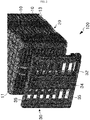
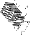
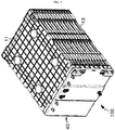
- FIG. 1 is a perspective view showing a secondary battery module according to an embodiment of the present disclosure
- FIG. 2 is an exploded perspective view showing the secondary battery module according to an embodiment of the present disclosure.
- a compact secondary battery module 100 includes a cartridge assembly 20 in which a plurality of cartridges 10 accommodating cells 2, respectively, are stacked, and a sensing housing 30 coupled to a side of the cartridge assembly 20 by means of, for example, one-touch, snap-fitting, hooking or the like.
- the cartridge assembly 20 is prepared by stacking a plurality of cartridges 10 which are made by injection-molding plastic and respectively have an accommodation portion capable of accommodating the cell 2.
- the cartridges 10 may be coupled to each other by means of snap-fitting or hooking.
- a plurality of lead overlapping portions 16 where leads 12, 14 having opposite polarities of neighboring cells 2, for example a first lead 12 made of aluminum and having a first polarity and a second lead 14 made of copper and having a second polarity opposite to the first polarity, overlap with each other are located at the sidewall of each cartridge 10 with a predetermined pattern.
- the cartridge assembly 20 has an upper cover 11 and a lower cover 13, coupled to the cartridges 10 at both ends by means of, for example, hooking.
- the upper cover 11 and the lower cover 13 are injection-molded to have substantially the same shape as the individual cartridge 10 of the cartridge assembly 20, respectively. It will be understood by those skilled in the art that the upper cover 11 and the lower cover 13 have a function of protecting the cell 2 accommodated in the cartridges 10 at both ends and have a function and structure to finish and surround the appearance of the secondary battery module 100.
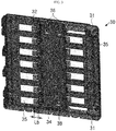
- FIG. 3 is a partial perspective view showing a sensing housing available for the secondary battery module according to an embodiment of the present disclosure
- FIG. 4 is a partial perspective view showing a cartridge assembly available for the secondary battery module according to an embodiment of the present disclosure
- FIG. 5 is an enlarged view showing a portion A of FIG. 4 .
- the sensing housing 30 is provided with a plurality of bus bars 32 corresponding to the lead overlapping portions 16, respectively.
- Each bus bar 32 may be made of, for example, copper.
- the sensing housing 30 may be injection-molded in an approximately rectangular shape by, for example, insulating plastic, and a plurality of accommodation holes 35 capable of respectively accommodating the bus bars 32 are formed therethrough in a predetermined pattern.
- a BMS circuit board 34 functioning to collect voltage and/or temperature data of each cell 2 sensed by the corresponding bus bar 32, balancing the corresponding cell 2 by means of the collected data, and transferring the data to another controller (not shown) of the module is installed.
- the BMS circuit board 34 is electrically connected to one end of each bus bar 32.
- the first lead 12 and the second lead 14 extend and bend from a side of each cell 2 by a predetermined length and have a predetermined width, respectively.
- the first lead 12 of each cell 2 is bent by 90 degrees upwards on the drawing, and the second lead 14 is bent 90 degrees downwards on the drawing.
- a width W1 of the first lead 12 is shorter than a width W2 of the second lead 14, and thus the sum of the width W1 of the first lead 12 and a length Lb of the bus bar 32, explained later, may be substantially identical to the width W2 of the second lead 14.
- the reference sign 36 represents a pair of data communication ports for exchanging data between BMS circuit board 34, when a plurality of secondary battery modules 100 are coupled, and the reference sign 38 represents a temperature data port for receiving a signal of a temperature sensor (not shown) for measuring an internal temperature of the secondary battery module 100.
- the reference sign 31 respectively represents a positive electrode terminal and a negative electrode terminal of the secondary battery module 100.
- the first lead 12 of the cell 2 of each lead overlapping portion 16 is configured to have a shorter width than the second lead 14 having a polarity opposite to the first lead 12 as much as a predetermined width, and when the sensing housing 30 is coupled to the cartridge assembly 20, the second lead 14 and the bus bar 32 may be welded by means of, for example, laser welding in a state where each corresponding bus bar 32 come into contact with the second lead 14 substantially on the same line as the first lead 12.
- the first lead 12, the second lead 14, and the bus bars 32 corresponding thereto may also be coupled together by ultrasonic welding.
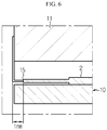
- FIG. 6 is a cross-sectioned view showing a curved portion of a secondary battery module according to an embodiment of the present disclosure
- FIG. 7 is a schematic diagram for illustrating a welding process between a bus bar of the sensing housing and each cell lead, when the secondary battery module according to an embodiment of the present disclosure is assembled.
- the sensing housing 30 is coupled to a side of the cartridge assembly 20 in a state where the first lead 12 and the second lead 14 of the cells 2 adjacent to the respective lead overlapping portions 16 overlap with each other in contact, thereby configuring the secondary battery module 100.
- the bus bar 32, the first lead 12 and the second lead 14 are positioned in order in a direction from the outside of the module 100, namely from a side where laser welding is performed, toward the cartridge assembly.
- each cartridge 10 has a barrier 18 on a side thereof in order to protect the cells 2 accommodated in each cartridge 10.
- the barrier 18 serves as a blocking wall to prevent a laser (not shown) emitting from a laser device (not shown) from being directly irradiated onto the cell 2.
- the leads 12, 14 of each cell 2 may be bent at a right angle at a point of about 0.8 to 1.2 mm from a lead insulating unit 15 in state of being accommodated in the corresponding cartridge.
- FIG. 8 which is an exploded perspective view showing the secondary battery module according to an embodiment of the present disclosure a the present disclosure, which is net yet completely assembled
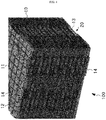
- FIG. 9 which is a perspective view in a completely assembled state, in a state where the sensing housing 30 is coupled to the cartridge assembly 20, a sensing cover 40 is coupled to the sensing housing 30 to protect the BMS circuit board 34 and bus bar 32.
- the sensing cover 40 may be coupled to the sensing housing 30 by means of snap-fitting or hooking.
- a plurality of cells 2 in which a width W1 of the first lead 12 is shorter than a width W2 of the second lead 14 (for example, as much as a length Lb of each bus bar 32, and leads 12, 14 with opposite polarities are bent in opposite directions.
- the width W1 of the first lead 12 may be shorter than the width W2 of the second lead 14 when the leads are initially manufactured, or the first lead 12 and the second lead 14 may be manufactured to have the same width and then the first lead 12 of each cell 2 may be cut by a predetermined length so that the first lead 12 have the width W1.
- the leads 12, 14 of the cell may be bent at a point of approximately 0.8 to 1.2 mm, preferably 1 mm, from the lead insulation portion 15 at a right angle, thereby maximizing the energy efficiency.
- a plurality of cartridges 10 respectively accommodating the cells 2 are stacked to form the cartridge assembly 20 so that the leads 12, 14 of the neighboring cells 2 with opposite polarities overlap with each other and thus the lead overlapping portions 16 are positioned in a predetermined pattern on the sidewall of the cartridges 10.
- Each cartridge 10 of the cartridge assembly 20 may include an accommodation portion capable of accommodating the cell 2, and may also have a hook or a slot so that a pair of adjacent cartridges 10 may be coupled to each other by means of snap-fitting or hooking, as being easily understood by those skilled in the art.
- the upper cover 11 and the lower cover 13 which may accommodate and protect the cell 2 are coupled to each other by means of, for example, snap-fitting or hooking.
- the cartridge 10 at which the first lead 12 and the second lead 14 are placed may employ a cartridge having a barrier 18 at a side thereof so that the cell 2 may be protected against the laser during the laser welding operation described below.
- the sensing housing 30 having a plurality of bus bars 32 respectively installed corresponding to respective lead overlapping portions 16 is coupled to a side of the cartridge assembly 20 by means of snap-fitting or hooking so that the corresponding bus bar 32 may come into contact with the second lead 14 substantially on the same line as the first lead 12.
- the bus bars 32 are arranged in the sensor housing 30 in advance with a predetermined pattern.
- the first lead 12 is made of aluminum
- the second lead 14 and the bus bar 32 are made of copper.
- each lead overlapping portion 16 is welded.
- a welding system having a plurality of welding points may be used, and also an individual laser welder may be used to perform point welding several times.
- a separate laser welder or welding point may be used between the first lead 12 and the second lead 14.
- the laser welder may irradiate laser in a direction substantially perpendicular to the sensing housing 30.
- the secondary battery modules 100 may electrically connected to each other in series or in parallel and are accommodated in a predetermined case to provide a compact secondary battery pack for a power storage device for a home photovoltaic (PV) solar energy panel.
- PV photovoltaic
- the present disclosure relates to a method for welding electrode leads of a secondary battery module and a compact secondary battery module using the same, and is particularly applicable to industries related to welding of electrode leads of a secondary battery module.
Landscapes
- Chemical & Material Sciences (AREA)
- Chemical Kinetics & Catalysis (AREA)
- General Chemical & Material Sciences (AREA)
- Electrochemistry (AREA)
- Engineering & Computer Science (AREA)
- Manufacturing & Machinery (AREA)
- Optics & Photonics (AREA)
- Physics & Mathematics (AREA)
- Inorganic Chemistry (AREA)
- Materials Engineering (AREA)
- Microelectronics & Electronic Packaging (AREA)
- Mechanical Engineering (AREA)
- Plasma & Fusion (AREA)
- Connection Of Batteries Or Terminals (AREA)
- Battery Mounting, Suspending (AREA)
- Sealing Battery Cases Or Jackets (AREA)
Abstract
Description
- The present disclosure relates to a method for welding electrode leads of a secondary battery module and a compact secondary battery module using the same, and more particularly, to a method for welding electrode leads and bus bars of a lithium secondary battery module and a lithium secondary battery module using the same.
- The present application claims priority to Korean Patent Application No.
10-2014-0188079 filed on December 24, 2014 - Along with technical development and increased demands on mobile devices, secondary batteries have been consumed more and more as energy sources. In the past, nickel cadmium batteries or hydrogen ion batteries have been used as secondary batteries, but recently, lithium ion batteries and lithium polymer batteries with a high energy density are widely used.
- Among these secondary batteries, a lithium secondary battery using lithium transition metal oxide, lithium complex oxide or the like as a positive electrode active material and ensuring high output and capacity receives a great interest. Generally, a lithium secondary battery has a structure in which an electrode assembly composed of a positive electrode, a separator and a negative electrode is embedded in a sealed container together with an electrolyte.
- Meanwhile, the lithium secondary battery includes a positive electrode, a negative electrode, and a separator and an electrolyte interposed therebetween. Depending on which material is used as a positive electrode active material and a negative electrode active material, the lithium secondary battery is classified into a lithium ion battery (LIB), a polymer lithium ion battery (PLIB) and so on. Typically, electrodes of these lithium secondary batteries are formed by applying a positive electrode active material or a negative electrode active material to a current collector such as aluminum or copper sheet, mesh, film, or foil, and then drying the same.
- In the secondary battery module, cells accommodated in each cartridge by performing welding, bolting, riveting or the like between cell leads. In addition, when cells are arranged in series or in parallel in the secondary battery module, three members, namely the positive electrode lead made of aluminum, the negative electrode lead made of copper and the bus bar made of copper and disposed for sensing should be electrically connected by using the above method.
- According to the prior art, there are various secondary battery modules, and the cartridges of the modules and bus bars for sensing are structured and located in different ways. For this reason, it is difficult to efficiently perform the connection work and the welding quality of the sensing structure is deteriorated. In addition, an unnecessary space of the secondary battery module should be provided for welding or the like, and resultantly energy density of the secondary battery module is lowered.
- In addition, secondary battery modules used in energy storage devices or power storage devices have been developed for designing developing secondary battery modules as compact as possible in order to increase energy efficiency or density.
- Meanwhile, in the configuration of a general secondary battery module, when welding (especially, laser welding) is performed to electrode leads (Al) (Cu) and bus bars (Cu) of cells, due to the different melting points of materials, generally, base materials are disposed in the order of an aluminum lead, a copper lead and bus bars, and then laser is irradiated from a cell lead for welding. However, if welding is performed in this order, the cell lead may be deformed first by the laser.
- The present disclosure is designed to solve the problems of the related art, and therefore the present disclosure is directed to providing a method for welding electrode leads of a secondary battery module with an improved structure, in which when corresponding electrode leads of adjacent cells of a secondary battery module overlap with each other in contact, the lead made of a different material of a bus bar is partially cut, and the bus bar is located at the cut portion so that the bus bar is welded to a lead made of the same material. The present disclosure is also directed to providing a compact secondary battery module using the method.
- In one aspect of the present disclosure, there is provided a compact secondary battery module, comprising: a cartridge assembly having a plurality of cartridges stacked while accommodating cells, respectively, so that a plurality of lead overlapping portions where leads of adjacent cells overlap with each other are located at a cartridge sidewall with a predetermined pattern; and a sensing housing having a plurality of bus bars located and welded corresponding to the lead overlapping portions, respectively, the sensing housing being capable of being arranged at a side of the cartridge assembly, wherein a first lead of a cell of each lead overlapping portion is configured to have a shorter width than a second lead having a polarity opposite to the first lead as much as a predetermined width, and in a state where the sensing housing is coupled to the cartridge assembly, a corresponding bus bar comes into contact with the second lead substantially on the same line as the first lead, and the second lead and the bus bar are welded to each other.
- Preferably, the secondary battery module may further comprise a barrier provided at a side of each cartridge to protect the cell during a welding work.
- Preferably, the lead of each cell may be bent at a right angle at about 1 mm from a lead insulation portion in a state of being accommodated in the corresponding cartridge.
- Preferably, the welding may be laser welding.
- Preferably, in the laser welding, laser may be irradiated substantially perpendicular to the sensing housing.
- Preferably, the bus bar and the second lead may be made of copper, and the first lead may be made of aluminum.
- Preferably, the sensing housing may further include a battery management system (BMS) circuit board configured to manage voltage and/or temperature data of each cell detected by each bus bar.
- Preferably, the sensing housing may be coupled to the cartridge assembly by means of snap-fitting or hooking.
- Preferably, the secondary battery module may further comprise a sensing cover coupled to the sensing housing.
- Preferably, the sensing cover may be coupled to the sensing housing by means of snap-fitting or hooking.
- Preferably, two neighboring cartridges of the cartridge assembly may be coupled to each other by means of hooking.
- Preferably, the cartridge assembly may further include an upper cover and a lower cover coupled to cartridges at both ends thereof by means of hooking.
- In another aspect of the present disclosure, there is also provided a method for welding electrode leads of a compact secondary battery module, comprising: (a) preparing a plurality of cells having leads which have opposite polarities and are bent in opposite directions so that a first lead is formed to have a shorter width than a second lead as much as a predetermined width; (b) forming a cartridge assembly by stacking a plurality of cartridges accommodating cells, respectively, so that lead overlapping portions where leads of adjacent cells with opposite polarities overlap with each other are formed at a cartridge sidewall with a predetermined pattern; (c) disposing a sensing housing having a plurality of bus bars respectively installed corresponding to the lead overlapping portions at a side of the cartridge assembly so that a corresponding bus bar comes into contact with the second lead substantially on the same line as the first lead; and (d) welding the second lead and the bus bar of each lead overlapping portion.
- Preferably, in the step (b), a cartridge having a barrier at each sidewall where the first lead and the second lead are disposed may be used.
- Preferably, in the step (a), each lead may be bent at a right angle at about 1 mm from a lead insulation portion of the cell in a state of being accommodated in the corresponding cartridge.
- Preferably, the step (d) may use a laser welder.
- Preferably, a laser irradiation direction of the laser welder may be substantially perpendicular to the sensing housing.
- Preferably, the bus bar and the second lead may be made of copper, and the first lead may be made of aluminum.
- In another aspect of the present disclosure, there is also provided a compact secondary battery module, manufactured by the above method.
- In another aspect of the present disclosure, there is also provided a secondary battery packing, in the compact secondary battery modules as described above are coupled.
- The method for welding electrode terminals of a secondary battery module and the compact secondary battery module using the same according to embodiments of the present disclosure give the following effects.
- First, a bending length of the lead of the cell is minimized, and while assembling a structure to which the bus bar is attached is assembled to a side of the cartridge assembly, a lead of the cell made of the same material as the bus bar may be welded to the bus bar so that the materials of the same kind are welded, thereby improving the welding quality of the sensing structure.
- Second, an unnecessary space is minimized in the module configuration, so that the module may be compactly constructed to improve the energy efficiency.
- Third, since the aluminum lead made of the same material as the bus bar may be cut off, the material cost of the lead may be reduced.
- Fourth, it is possible to prevent the damage of the lead by irradiating laser to the bus bar first in a welding irradiation direction, in the order of the welding base material between the cell leads and the bus bar.
- The accompanying drawings illustrate a preferred embodiment of the present disclosure and together with the foregoing disclosure, serve to provide further understanding of the technical features of the present disclosure, and thus, the present disclosure is not construed as being limited to the drawing.
-
FIG. 1 is a perspective view showing a secondary battery module according to an embodiment of the present disclosure. -
FIG. 2 is an exploded perspective view showing the secondary battery module according to an embodiment of the present disclosure. -
FIG. 3 is a partial perspective view showing a sensing housing available for the secondary battery module according to an embodiment of the present disclosure. -
FIG. 4 is a partial perspective view showing a cartridge assembly available for the secondary battery module according to an embodiment of the present disclosure. -
FIG. 5 is an enlarged view showing a portion A ofFIG. 4 . -
FIG. 6 is a cross-sectioned view showing a curved portion of a lead of a cell of the secondary battery module according to an embodiment of the present disclosure. -
FIG. 7 is a schematic diagram for illustrating a welding process between a bus bar of the sensing housing and each cell lead, when the secondary battery module according to an embodiment of the present disclosure is assembled. -
FIG. 8 is an exploded perspective view showing a secondary battery module according to an embodiment of the present disclosure. -
FIG. 9 is a perspective view ofFIG. 8 in an assembled state. - Hereinafter, preferred embodiments of the present disclosure will be described in detail with reference to the accompanying drawings. Prior to the description, it should be understood that the terms used in the specification and the appended claims should not be construed as limited to general and dictionary meanings, but interpreted based on the meanings and concepts corresponding to technical aspects of the present disclosure on the basis of the principle that the inventor is allowed to define terms appropriately for the best explanation.
- Therefore, the description proposed herein is just a preferable example for the purpose of illustrations only, not intended to limit the scope of the disclosure, so it should be understood that other equivalents and modifications could be made thereto without departing from the scope of the disclosure.
-
FIG. 1 is a perspective view showing a secondary battery module according to an embodiment of the present disclosure, andFIG. 2 is an exploded perspective view showing the secondary battery module according to an embodiment of the present disclosure. - Referring to
FIGS. 1 and2 , a compactsecondary battery module 100 according to an embodiment of the present disclosure includes acartridge assembly 20 in which a plurality ofcartridges 10accommodating cells 2, respectively, are stacked, and asensing housing 30 coupled to a side of thecartridge assembly 20 by means of, for example, one-touch, snap-fitting, hooking or the like. - The
cartridge assembly 20 is prepared by stacking a plurality ofcartridges 10 which are made by injection-molding plastic and respectively have an accommodation portion capable of accommodating thecell 2. Thecartridges 10 may be coupled to each other by means of snap-fitting or hooking. As shown inFIG. 6 , in thecartridge assembly 20, a plurality of lead overlappingportions 16 where leads 12, 14 having opposite polarities of neighboringcells 2, for example afirst lead 12 made of aluminum and having a first polarity and asecond lead 14 made of copper and having a second polarity opposite to the first polarity, overlap with each other are located at the sidewall of eachcartridge 10 with a predetermined pattern. - In addition, the
cartridge assembly 20 has anupper cover 11 and alower cover 13, coupled to thecartridges 10 at both ends by means of, for example, hooking. Theupper cover 11 and thelower cover 13 are injection-molded to have substantially the same shape as theindividual cartridge 10 of thecartridge assembly 20, respectively. It will be understood by those skilled in the art that theupper cover 11 and thelower cover 13 have a function of protecting thecell 2 accommodated in thecartridges 10 at both ends and have a function and structure to finish and surround the appearance of thesecondary battery module 100. -
FIG. 3 is a partial perspective view showing a sensing housing available for the secondary battery module according to an embodiment of the present disclosure,FIG. 4 is a partial perspective view showing a cartridge assembly available for the secondary battery module according to an embodiment of the present disclosure, andFIG. 5 is an enlarged view showing a portion A ofFIG. 4 . - Referring to
FIGS. 1 to 5 , the sensinghousing 30 is provided with a plurality ofbus bars 32 corresponding to the lead overlappingportions 16, respectively. Eachbus bar 32 may be made of, for example, copper. In addition, the sensinghousing 30 may be injection-molded in an approximately rectangular shape by, for example, insulating plastic, and a plurality ofaccommodation holes 35 capable of respectively accommodating the bus bars 32 are formed therethrough in a predetermined pattern. At an approximate center of the sensinghousing 30, aBMS circuit board 34 functioning to collect voltage and/or temperature data of eachcell 2 sensed by the correspondingbus bar 32, balancing thecorresponding cell 2 by means of the collected data, and transferring the data to another controller (not shown) of the module is installed. TheBMS circuit board 34 is electrically connected to one end of eachbus bar 32. - The
first lead 12 and thesecond lead 14 extend and bend from a side of eachcell 2 by a predetermined length and have a predetermined width, respectively. Thefirst lead 12 of eachcell 2 is bent by 90 degrees upwards on the drawing, and thesecond lead 14 is bent 90 degrees downwards on the drawing. As shown inFIG. 5 , a width W1 of thefirst lead 12 is shorter than a width W2 of thesecond lead 14, and thus the sum of the width W1 of thefirst lead 12 and a length Lb of thebus bar 32, explained later, may be substantially identical to the width W2 of thesecond lead 14. - In
FIG. 3 , thereference sign 36 represents a pair of data communication ports for exchanging data betweenBMS circuit board 34, when a plurality ofsecondary battery modules 100 are coupled, and thereference sign 38 represents a temperature data port for receiving a signal of a temperature sensor (not shown) for measuring an internal temperature of thesecondary battery module 100. Thereference sign 31 respectively represents a positive electrode terminal and a negative electrode terminal of thesecondary battery module 100. - As described above, the
first lead 12 of thecell 2 of each lead overlappingportion 16 is configured to have a shorter width than thesecond lead 14 having a polarity opposite to thefirst lead 12 as much as a predetermined width, and when the sensinghousing 30 is coupled to thecartridge assembly 20, thesecond lead 14 and thebus bar 32 may be welded by means of, for example, laser welding in a state where each correspondingbus bar 32 come into contact with thesecond lead 14 substantially on the same line as thefirst lead 12. According to a modified embodiment, it would be understood by those skilled in the art that thefirst lead 12, thesecond lead 14, and the bus bars 32 corresponding thereto may also be coupled together by ultrasonic welding. -
FIG. 6 is a cross-sectioned view showing a curved portion of a secondary battery module according to an embodiment of the present disclosure, andFIG. 7 is a schematic diagram for illustrating a welding process between a bus bar of the sensing housing and each cell lead, when the secondary battery module according to an embodiment of the present disclosure is assembled. - Referring to
FIGS. 6 and7 , the sensinghousing 30 is coupled to a side of thecartridge assembly 20 in a state where thefirst lead 12 and thesecond lead 14 of thecells 2 adjacent to the respectivelead overlapping portions 16 overlap with each other in contact, thereby configuring thesecondary battery module 100. In this case, thebus bar 32, thefirst lead 12 and thesecond lead 14 are positioned in order in a direction from the outside of themodule 100, namely from a side where laser welding is performed, toward the cartridge assembly. In this arrangement, when welding is performed between theleads bus bar 32 and theleads housing 30, eachcartridge 10 has abarrier 18 on a side thereof in order to protect thecells 2 accommodated in eachcartridge 10. It will be fully understood by those skilled in the art that thebarrier 18 serves as a blocking wall to prevent a laser (not shown) emitting from a laser device (not shown) from being directly irradiated onto thecell 2. - According to an embodiment of the present disclosure, in order to configure the secondary battery module in a compact design to enhance energy efficiency to the maximum, the
leads cell 2 may be bent at a right angle at a point of about 0.8 to 1.2 mm from a lead insulatingunit 15 in state of being accommodated in the corresponding cartridge. - Referring to
FIG. 8 which is an exploded perspective view showing the secondary battery module according to an embodiment of the present disclosure a the present disclosure, which is net yet completely assembled, andFIG. 9 which is a perspective view in a completely assembled state, in a state where the sensinghousing 30 is coupled to thecartridge assembly 20, asensing cover 40 is coupled to the sensinghousing 30 to protect theBMS circuit board 34 andbus bar 32. Thesensing cover 40 may be coupled to the sensinghousing 30 by means of snap-fitting or hooking. - A method for welding electrode leads of a secondary battery module according to another embodiment of the present disclosure will be described.
- First, a plurality of
cells 2 in which a width W1 of thefirst lead 12 is shorter than a width W2 of the second lead 14 (for example, as much as a length Lb of eachbus bar 32, and leads 12, 14 with opposite polarities are bent in opposite directions. Here, it could be fully understood that the width W1 of thefirst lead 12 may be shorter than the width W2 of thesecond lead 14 when the leads are initially manufactured, or thefirst lead 12 and thesecond lead 14 may be manufactured to have the same width and then thefirst lead 12 of eachcell 2 may be cut by a predetermined length so that thefirst lead 12 have the width W1. In addition, in a state where thecell 2 is accommodated in the correspondingcartridge 10, theleads lead insulation portion 15 at a right angle, thereby maximizing the energy efficiency. - Subsequently, a plurality of
cartridges 10 respectively accommodating thecells 2 are stacked to form thecartridge assembly 20 so that the leads 12, 14 of the neighboringcells 2 with opposite polarities overlap with each other and thus the lead overlappingportions 16 are positioned in a predetermined pattern on the sidewall of thecartridges 10. Eachcartridge 10 of thecartridge assembly 20 may include an accommodation portion capable of accommodating thecell 2, and may also have a hook or a slot so that a pair ofadjacent cartridges 10 may be coupled to each other by means of snap-fitting or hooking, as being easily understood by those skilled in the art. In addition, at both sides of thecartridge assembly 20, theupper cover 11 and thelower cover 13 which may accommodate and protect thecell 2 are coupled to each other by means of, for example, snap-fitting or hooking. In addition, thecartridge 10 at which thefirst lead 12 and thesecond lead 14 are placed may employ a cartridge having abarrier 18 at a side thereof so that thecell 2 may be protected against the laser during the laser welding operation described below. - Next, the sensing
housing 30 having a plurality ofbus bars 32 respectively installed corresponding to respective lead overlappingportions 16 is coupled to a side of thecartridge assembly 20 by means of snap-fitting or hooking so that the correspondingbus bar 32 may come into contact with thesecond lead 14 substantially on the same line as thefirst lead 12. In this case, as described above, the bus bars 32 are arranged in thesensor housing 30 in advance with a predetermined pattern. Here, thefirst lead 12 is made of aluminum, and thesecond lead 14 and thebus bar 32 are made of copper. - Finally, the
second lead 14 and thebus bar 32 of each lead overlappingportion 16 are welded. In this stage, a welding system having a plurality of welding points may be used, and also an individual laser welder may be used to perform point welding several times. In addition, it would be fully understood by those skilled in the art that a separate laser welder or welding point may be used between thefirst lead 12 and thesecond lead 14. Moreover, the laser welder may irradiate laser in a direction substantially perpendicular to the sensinghousing 30. - The
secondary battery modules 100 according to the above embodiments may electrically connected to each other in series or in parallel and are accommodated in a predetermined case to provide a compact secondary battery pack for a power storage device for a home photovoltaic (PV) solar energy panel. - The foregoing description is merely illustrative of the technical features of the present disclosure, and various modifications and variations can be made by those having ordinary skill in the art without departing from the essential characteristics of the present disclosure. Therefore, the embodiments disclosed herein are not intended to limit but to illustrate the technical features of the present disclosure, and the scope of the technical features of the present disclosure is not limited by these embodiments. The scope of the present disclosure should be construed according to the appended claims, and all technical features falling within its equivalent scope should be construed as being included in the scope of the present disclosure.
- The present disclosure relates to a method for welding electrode leads of a secondary battery module and a compact secondary battery module using the same, and is particularly applicable to industries related to welding of electrode leads of a secondary battery module.
Claims (20)
- A compact secondary battery module, comprising:a cartridge assembly having a plurality of cartridges stacked while accommodating cells, respectively, so that a plurality of lead overlapping portions where leads of adjacent cells overlap with each other are located at a cartridge sidewall with a predetermined pattern; anda sensing housing having a plurality of bus bars located and welded corresponding to the lead overlapping portions, respectively, the sensing housing being capable of being arranged at a side of the cartridge assembly,wherein a first lead of a cell of each lead overlapping portion is configured to have a shorter width than a second lead having a polarity opposite to the first lead as much as a predetermined width, and in a state where the sensing housing is coupled to the cartridge assembly, a corresponding bus bar comes into contact with the second lead substantially on the same line as the first lead, and the second lead and the bus bar are welded to each other.
- The compact secondary battery module according to claim 1, further comprising:a barrier provided at a side of each cartridge to protect the cell during a welding work.
- The compact secondary battery module according to claim 1,
wherein the lead of each cell is bent at a right angle at about 1 mm from a lead insulation portion in a state of being accommodated in the corresponding cartridge. - The compact secondary battery module according to claim 1,
wherein the welding is laser welding. - The compact secondary battery module according to claim 4,
wherein in the laser welding, laser is irradiated substantially perpendicular to the sensing housing. - The compact secondary battery module according to claim 1,
wherein the bus bar and the second lead are made of copper, and the first lead is made of aluminum. - The compact secondary battery module according to claim 1,
wherein the sensing housing further includes a battery management system (BMS) circuit board configured to manage voltage and/or temperature data of each cell detected by each bus bar. - The compact secondary battery module according to claim 7,
wherein the sensing housing is coupled to the cartridge assembly by means of snap-fitting or hooking. - The compact secondary battery module according to claim 7, further comprising:a sensing cover coupled to the sensing housing.
- The compact secondary battery module according to claim 9,
wherein the sensing cover is coupled to the sensing housing by means of snap-fitting or hooking. - The compact secondary battery module according to claim 1,
wherein two neighboring cartridges of the cartridge assembly are coupled to each other by means of hooking. - The compact secondary battery module according to claim 1,
wherein the cartridge assembly further includes an upper cover and a lower cover coupled to cartridges at both ends thereof by means of hooking. - A method for welding electrode leads of a compact secondary battery module, comprising:(a) preparing a plurality of cells having leads which have opposite polarities and are bent in opposite directions so that a first lead is formed to have a shorter width than a second lead as much as a predetermined width;(b) forming a cartridge assembly by stacking a plurality of cartridges accommodating cells, respectively, so that lead overlapping portions where leads of adjacent cells with opposite polarities overlap with each other are formed at a cartridge sidewall with a predetermined pattern;(c) disposing a sensing housing having a plurality of bus bars respectively installed corresponding to the lead overlapping portions at a side of the cartridge assembly so that a corresponding bus bar comes into contact with the second lead substantially on the same line as the first lead; and(d) welding the second lead and the bus bar of each lead overlapping portion.
- The method for welding electrode leads of a compact secondary battery module according to claim 13,
wherein in the step (b), a cartridge having a barrier at each sidewall where the first lead and the second lead are disposed is used. - The method for welding electrode leads of a compact secondary battery module according to claim 13,
wherein in the step (a), each lead is bent at a right angle at about 1 mm from a lead insulation portion of the cell in a state of being accommodated in the corresponding cartridge. - The method for welding electrode leads of a compact secondary battery module according to claim 13,
wherein the step (d) uses a laser welder. - The method for welding electrode leads of a compact secondary battery module according to claim 16,
wherein a laser irradiation direction of the laser welder is substantially perpendicular to the sensing housing. - The method for welding electrode leads of a compact secondary battery module according to claim 13,
wherein the bus bar and the second lead are made of copper, and the first lead is made of aluminum. - A compact secondary battery module, manufactured by the method of claim 13 to 18.
- A secondary battery pack, comprising the compact secondary battery module defined in claim 19.
Applications Claiming Priority (2)
| Application Number | Priority Date | Filing Date | Title |
|---|---|---|---|
| KR1020140188079A KR101817237B1 (en) | 2014-12-24 | 2014-12-24 | Method for welding of electrode-leads & secondary battery module utilizing thereof |
| PCT/KR2015/014282 WO2016105169A1 (en) | 2014-12-24 | 2015-12-24 | Method for welding electrode leads of secondary battery module, and compact secondary battery module for which the method has been used |
Publications (3)
| Publication Number | Publication Date |
|---|---|
| EP3220449A1 true EP3220449A1 (en) | 2017-09-20 |
| EP3220449A4 EP3220449A4 (en) | 2018-08-01 |
| EP3220449B1 EP3220449B1 (en) | 2025-06-25 |
Family
ID=56151084
Family Applications (1)
| Application Number | Title | Priority Date | Filing Date |
|---|---|---|---|
| EP15873696.7A Active EP3220449B1 (en) | 2014-12-24 | 2015-12-24 | Method for welding electrode leads of secondary battery module and compact secondary battery module using the same |
Country Status (8)
| Country | Link |
|---|---|
| US (1) | US10629881B2 (en) |
| EP (1) | EP3220449B1 (en) |
| JP (1) | JP6440002B2 (en) |
| KR (1) | KR101817237B1 (en) |
| CN (1) | CN107112485B (en) |
| ES (1) | ES3036265T3 (en) |
| HU (1) | HUE072268T2 (en) |
| WO (1) | WO2016105169A1 (en) |
Cited By (3)
| Publication number | Priority date | Publication date | Assignee | Title |
|---|---|---|---|---|
| WO2019069912A1 (en) * | 2017-10-03 | 2019-04-11 | カルソニックカンセイ株式会社 | Method of manufacturing assembled battery and assembled battery |
| EP3537509A4 (en) * | 2016-11-07 | 2019-10-23 | Envision AESC Japan Ltd. | SPACER, ASSEMBLY BATTERY, AND METHOD FOR MANUFACTURING ASSEMBLY BATTERY |
| EP4018494A4 (en) * | 2019-06-17 | 2023-08-09 | Dongguan Amperex Technology Limited | BATTERY AND ELECTROCHEMICAL DEVICE ASSEMBLY |
Families Citing this family (20)
| Publication number | Priority date | Publication date | Assignee | Title |
|---|---|---|---|---|
| JP6365437B2 (en) * | 2015-06-24 | 2018-08-01 | 株式会社オートネットワーク技術研究所 | Wiring module and power storage module |
| KR102657330B1 (en) * | 2016-12-14 | 2024-04-15 | 현대자동차주식회사 | Battery module |
| US11088410B2 (en) * | 2016-12-23 | 2021-08-10 | Sk Innovation Co., Ltd. | Battery module |
| KR102209769B1 (en) | 2017-06-07 | 2021-01-28 | 주식회사 엘지화학 | Battery Module |
| KR102187067B1 (en) | 2017-08-10 | 2020-12-04 | 주식회사 엘지화학 | Battery module and method for producing the same |
| KR102155888B1 (en) | 2017-09-11 | 2020-09-14 | 주식회사 엘지화학 | Laser welding jig and laser welding apparatus comprising the same |
| JP6472858B1 (en) * | 2017-10-03 | 2019-02-20 | カルソニックカンセイ株式会社 | Assembled battery |
| KR102198848B1 (en) | 2017-11-16 | 2021-01-05 | 주식회사 엘지화학 | Battery Module Having Sensing Assembly and Busbar Assembly |
| CN108461802A (en) * | 2018-04-09 | 2018-08-28 | 江西恒动新能源有限公司 | A kind of energy-storage module battery core puts structure and puts method |
| KR102313030B1 (en) * | 2018-06-29 | 2021-10-13 | 주식회사 엘지에너지솔루션 | Automatic pressing jig apparatus that closely contacts electrode lead with bus bar |
| KR102258177B1 (en) * | 2018-09-20 | 2021-05-28 | 주식회사 엘지에너지솔루션 | Battery module, battery pack comprising the battery module and vehicle comprising the battery pack |
| CN109175679B (en) * | 2018-10-29 | 2024-09-27 | 武汉逸飞激光智能装备有限公司 | Welding system |
| KR102366138B1 (en) | 2018-12-06 | 2022-02-22 | 주식회사 엘지에너지솔루션 | Battery module |
| CN117578035A (en) * | 2019-06-17 | 2024-02-20 | 东莞新能安科技有限公司 | Battery components and electrochemical devices |
| CN110828598B (en) * | 2019-10-30 | 2024-03-08 | 江苏朗道新能源有限公司 | Half-sheet laminated tile assembly and manufacturing method thereof |
| KR20210132397A (en) | 2020-04-27 | 2021-11-04 | 주식회사 엘지에너지솔루션 | Battery module and battery pack including the same |
| KR102821825B1 (en) * | 2020-07-22 | 2025-06-16 | 주식회사 엘지에너지솔루션 | Battery module having a simple connection structure between cell lead and voltage sensing member and battery pack including the same |
| CN116368671A (en) * | 2021-02-23 | 2023-06-30 | 株式会社 Lg新能源 | Battery module and manufacturing method thereof |
| CN120500766B (en) * | 2022-12-28 | 2026-05-08 | Cps科技控股有限公司 | Sensing connection method |
| KR20250009035A (en) * | 2023-07-10 | 2025-01-17 | 주식회사 엘지에너지솔루션 | Electrode lead welding method |
Family Cites Families (8)
| Publication number | Priority date | Publication date | Assignee | Title |
|---|---|---|---|---|
| KR100876458B1 (en) | 2004-12-24 | 2008-12-29 | 주식회사 엘지화학 | Battery cartridge of novel structure and open battery module containing it |
| KR101136800B1 (en) | 2008-02-29 | 2012-04-19 | 주식회사 엘지화학 | Process for Preparation of Battery Module and Middle- or Large-sized Battery Pack Using the Same |
| EP2416436B1 (en) * | 2009-04-01 | 2018-02-21 | LG Chem, Ltd. | Voltage-detecting member, and battery module including same |
| KR101298872B1 (en) * | 2011-12-28 | 2013-08-21 | 에이치엘그린파워 주식회사 | Housing structure of Battery module |
| KR101459400B1 (en) * | 2012-03-26 | 2014-11-07 | 주식회사 엘지화학 | Battery Module Assembly |
| KR101924193B1 (en) * | 2012-06-20 | 2018-12-03 | 에스케이이노베이션 주식회사 | Method of welding battery module and welding construction of battery module |
| KR20140056836A (en) | 2012-11-01 | 2014-05-12 | 주식회사 엘지화학 | Battery module and battery pack comprising the same |
| JP6107442B2 (en) * | 2013-06-06 | 2017-04-05 | 株式会社オートネットワーク技術研究所 | Power storage module |
-
2014
- 2014-12-24 KR KR1020140188079A patent/KR101817237B1/en active Active
-
2015
- 2015-12-24 ES ES15873696T patent/ES3036265T3/en active Active
- 2015-12-24 CN CN201580070618.8A patent/CN107112485B/en active Active
- 2015-12-24 HU HUE15873696A patent/HUE072268T2/en unknown
- 2015-12-24 JP JP2017530003A patent/JP6440002B2/en active Active
- 2015-12-24 WO PCT/KR2015/014282 patent/WO2016105169A1/en not_active Ceased
- 2015-12-24 EP EP15873696.7A patent/EP3220449B1/en active Active
- 2015-12-24 US US15/533,855 patent/US10629881B2/en active Active
Cited By (5)
| Publication number | Priority date | Publication date | Assignee | Title |
|---|---|---|---|---|
| EP3537509A4 (en) * | 2016-11-07 | 2019-10-23 | Envision AESC Japan Ltd. | SPACER, ASSEMBLY BATTERY, AND METHOD FOR MANUFACTURING ASSEMBLY BATTERY |
| WO2019069912A1 (en) * | 2017-10-03 | 2019-04-11 | カルソニックカンセイ株式会社 | Method of manufacturing assembled battery and assembled battery |
| JP2019067675A (en) * | 2017-10-03 | 2019-04-25 | カルソニックカンセイ株式会社 | Method of manufacturing assembled battery and assembled battery |
| US11322805B2 (en) | 2017-10-03 | 2022-05-03 | Marelli Corporation | Method of manufacturing battery pack and battery pack |
| EP4018494A4 (en) * | 2019-06-17 | 2023-08-09 | Dongguan Amperex Technology Limited | BATTERY AND ELECTROCHEMICAL DEVICE ASSEMBLY |
Also Published As
| Publication number | Publication date |
|---|---|
| WO2016105169A1 (en) | 2016-06-30 |
| US10629881B2 (en) | 2020-04-21 |
| EP3220449B1 (en) | 2025-06-25 |
| JP2017539061A (en) | 2017-12-28 |
| CN107112485B (en) | 2020-04-28 |
| KR101817237B1 (en) | 2018-01-11 |
| US20170331097A1 (en) | 2017-11-16 |
| HUE072268T2 (en) | 2025-11-28 |
| KR20160077765A (en) | 2016-07-04 |
| CN107112485A (en) | 2017-08-29 |
| JP6440002B2 (en) | 2018-12-19 |
| ES3036265T3 (en) | 2025-09-16 |
| EP3220449A4 (en) | 2018-08-01 |
Similar Documents
| Publication | Publication Date | Title |
|---|---|---|
| EP3220449B1 (en) | Method for welding electrode leads of secondary battery module and compact secondary battery module using the same | |
| US10481208B2 (en) | Method for welding electrode leads of secondary battery module and compact secondary battery module using the same | |
| KR101720618B1 (en) | Battery module having bus bar holder | |
| KR101808310B1 (en) | Compact secondary battery module integrated with BMS | |
| KR102047482B1 (en) | Battery module and battery pack including the same | |
| EP3550635B1 (en) | Battery module and battery pack including the same | |
| US11158895B2 (en) | Battery module, battery pack including battery module, and vehicle including battery pack | |
| US20180159096A1 (en) | Battery module and battery pack including same | |
| KR102444124B1 (en) | Battery module and battery pack comprising same | |
| JP6633193B2 (en) | battery pack | |
| EP3547394A1 (en) | Battery module, battery pack comprising same and battery module manufacturing method | |
| KR101984314B1 (en) | Secondary battery | |
| EP3783693B1 (en) | Battery module, battery pack comprising same battery module, and vehicle comprising same battery pack | |
| EP3582286A1 (en) | Battery cell frame and battery module comprising same | |
| KR20150089724A (en) | Battery Pack | |
| KR20150137840A (en) | Unit battery module and Battery module having the same | |
| KR101783917B1 (en) | Compact secondary battery module having hook structure | |
| EP3675235A1 (en) | Cylindrical secondary battery module | |
| KR101839653B1 (en) | Compact secondary battery module |
Legal Events
| Date | Code | Title | Description |
|---|---|---|---|
| STAA | Information on the status of an ep patent application or granted ep patent |
Free format text: STATUS: THE INTERNATIONAL PUBLICATION HAS BEEN MADE |
|
| PUAI | Public reference made under article 153(3) epc to a published international application that has entered the european phase |
Free format text: ORIGINAL CODE: 0009012 |
|
| STAA | Information on the status of an ep patent application or granted ep patent |
Free format text: STATUS: REQUEST FOR EXAMINATION WAS MADE |
|
| 17P | Request for examination filed |
Effective date: 20170616 |
|
| AK | Designated contracting states |
Kind code of ref document: A1 Designated state(s): AL AT BE BG CH CY CZ DE DK EE ES FI FR GB GR HR HU IE IS IT LI LT LU LV MC MK MT NL NO PL PT RO RS SE SI SK SM TR |
|
| AX | Request for extension of the european patent |
Extension state: BA ME |
|
| DAV | Request for validation of the european patent (deleted) | ||
| DAX | Request for extension of the european patent (deleted) | ||
| A4 | Supplementary search report drawn up and despatched |
Effective date: 20180629 |
|
| RIC1 | Information provided on ipc code assigned before grant |
Ipc: H01M 10/48 20060101ALI20180625BHEP Ipc: H01M 2/20 20060101AFI20180625BHEP Ipc: H01M 2/10 20060101ALI20180625BHEP Ipc: H01M 10/0525 20100101ALN20180625BHEP Ipc: H01M 10/42 20060101ALI20180625BHEP |
|
| RAP1 | Party data changed (applicant data changed or rights of an application transferred) |
Owner name: LG ENERGY SOLUTION LTD. |
|
| RAP3 | Party data changed (applicant data changed or rights of an application transferred) |
Owner name: LG ENERGY SOLUTION, LTD. |
|
| STAA | Information on the status of an ep patent application or granted ep patent |
Free format text: STATUS: EXAMINATION IS IN PROGRESS |
|
| 17Q | First examination report despatched |
Effective date: 20220725 |
|
| REG | Reference to a national code |
Ref country code: DE Ref legal event code: R079 Free format text: PREVIOUS MAIN CLASS: H01M0002200000 Ipc: H01M0010480000 Ref country code: DE Ref legal event code: R079 Ref document number: 602015091901 Country of ref document: DE Free format text: PREVIOUS MAIN CLASS: H01M0002200000 Ipc: H01M0010480000 |
|
| RIC1 | Information provided on ipc code assigned before grant |
Ipc: H01M 10/42 20060101ALI20241111BHEP Ipc: H01M 10/48 20060101AFI20241111BHEP |
|
| GRAP | Despatch of communication of intention to grant a patent |
Free format text: ORIGINAL CODE: EPIDOSNIGR1 |
|
| STAA | Information on the status of an ep patent application or granted ep patent |
Free format text: STATUS: GRANT OF PATENT IS INTENDED |
|
| INTG | Intention to grant announced |
Effective date: 20250219 |
|
| P01 | Opt-out of the competence of the unified patent court (upc) registered |
Free format text: CASE NUMBER: APP_13932/2025 Effective date: 20250321 |
|
| GRAS | Grant fee paid |
Free format text: ORIGINAL CODE: EPIDOSNIGR3 |
|
| GRAA | (expected) grant |
Free format text: ORIGINAL CODE: 0009210 |
|
| STAA | Information on the status of an ep patent application or granted ep patent |
Free format text: STATUS: THE PATENT HAS BEEN GRANTED |
|
| AK | Designated contracting states |
Kind code of ref document: B1 Designated state(s): AL AT BE BG CH CY CZ DE DK EE ES FI FR GB GR HR HU IE IS IT LI LT LU LV MC MK MT NL NO PL PT RO RS SE SI SK SM TR |
|
| REG | Reference to a national code |
Ref country code: GB Ref legal event code: FG4D |
|
| REG | Reference to a national code |
Ref country code: CH Ref legal event code: EP |
|
| REG | Reference to a national code |
Ref country code: DE Ref legal event code: R096 Ref document number: 602015091901 Country of ref document: DE |
|
| REG | Reference to a national code |
Ref country code: CH Ref legal event code: EP |
|
| REG | Reference to a national code |
Ref country code: IE Ref legal event code: FG4D |
|
| REG | Reference to a national code |
Ref country code: ES Ref legal event code: FG2A Ref document number: 3036265 Country of ref document: ES Kind code of ref document: T3 Effective date: 20250916 |
|
| PG25 | Lapsed in a contracting state [announced via postgrant information from national office to epo] |
Ref country code: FI Free format text: LAPSE BECAUSE OF FAILURE TO SUBMIT A TRANSLATION OF THE DESCRIPTION OR TO PAY THE FEE WITHIN THE PRESCRIBED TIME-LIMIT Effective date: 20250625 |
|
| REG | Reference to a national code |
Ref country code: LT Ref legal event code: MG9D |
|
| PG25 | Lapsed in a contracting state [announced via postgrant information from national office to epo] |
Ref country code: GR Free format text: LAPSE BECAUSE OF FAILURE TO SUBMIT A TRANSLATION OF THE DESCRIPTION OR TO PAY THE FEE WITHIN THE PRESCRIBED TIME-LIMIT Effective date: 20250926 Ref country code: NO Free format text: LAPSE BECAUSE OF FAILURE TO SUBMIT A TRANSLATION OF THE DESCRIPTION OR TO PAY THE FEE WITHIN THE PRESCRIBED TIME-LIMIT Effective date: 20250925 |
|
| PG25 | Lapsed in a contracting state [announced via postgrant information from national office to epo] |
Ref country code: BG Free format text: LAPSE BECAUSE OF FAILURE TO SUBMIT A TRANSLATION OF THE DESCRIPTION OR TO PAY THE FEE WITHIN THE PRESCRIBED TIME-LIMIT Effective date: 20250625 |
|
| PG25 | Lapsed in a contracting state [announced via postgrant information from national office to epo] |
Ref country code: HR Free format text: LAPSE BECAUSE OF FAILURE TO SUBMIT A TRANSLATION OF THE DESCRIPTION OR TO PAY THE FEE WITHIN THE PRESCRIBED TIME-LIMIT Effective date: 20250625 |
|
| PG25 | Lapsed in a contracting state [announced via postgrant information from national office to epo] |
Ref country code: RS Free format text: LAPSE BECAUSE OF FAILURE TO SUBMIT A TRANSLATION OF THE DESCRIPTION OR TO PAY THE FEE WITHIN THE PRESCRIBED TIME-LIMIT Effective date: 20250925 |
|
| PG25 | Lapsed in a contracting state [announced via postgrant information from national office to epo] |
Ref country code: LV Free format text: LAPSE BECAUSE OF FAILURE TO SUBMIT A TRANSLATION OF THE DESCRIPTION OR TO PAY THE FEE WITHIN THE PRESCRIBED TIME-LIMIT Effective date: 20250625 |
|
| REG | Reference to a national code |
Ref country code: NL Ref legal event code: MP Effective date: 20250625 |
|
| PG25 | Lapsed in a contracting state [announced via postgrant information from national office to epo] |
Ref country code: NL Free format text: LAPSE BECAUSE OF FAILURE TO SUBMIT A TRANSLATION OF THE DESCRIPTION OR TO PAY THE FEE WITHIN THE PRESCRIBED TIME-LIMIT Effective date: 20250625 |
|
| REG | Reference to a national code |
Ref country code: HU Ref legal event code: AG4A Ref document number: E072268 Country of ref document: HU |
|
| PG25 | Lapsed in a contracting state [announced via postgrant information from national office to epo] |
Ref country code: PT Free format text: LAPSE BECAUSE OF FAILURE TO SUBMIT A TRANSLATION OF THE DESCRIPTION OR TO PAY THE FEE WITHIN THE PRESCRIBED TIME-LIMIT Effective date: 20251027 |
|
| REG | Reference to a national code |
Ref country code: AT Ref legal event code: MK05 Ref document number: 1807544 Country of ref document: AT Kind code of ref document: T Effective date: 20250625 |
|
| PG25 | Lapsed in a contracting state [announced via postgrant information from national office to epo] |
Ref country code: IS Free format text: LAPSE BECAUSE OF FAILURE TO SUBMIT A TRANSLATION OF THE DESCRIPTION OR TO PAY THE FEE WITHIN THE PRESCRIBED TIME-LIMIT Effective date: 20251025 |
|
| PGFP | Annual fee paid to national office [announced via postgrant information from national office to epo] |
Ref country code: DE Payment date: 20251120 Year of fee payment: 11 |
|
| PGFP | Annual fee paid to national office [announced via postgrant information from national office to epo] |
Ref country code: GB Payment date: 20251120 Year of fee payment: 11 |
|
| PG25 | Lapsed in a contracting state [announced via postgrant information from national office to epo] |
Ref country code: AT Free format text: LAPSE BECAUSE OF FAILURE TO SUBMIT A TRANSLATION OF THE DESCRIPTION OR TO PAY THE FEE WITHIN THE PRESCRIBED TIME-LIMIT Effective date: 20250625 Ref country code: SM Free format text: LAPSE BECAUSE OF FAILURE TO SUBMIT A TRANSLATION OF THE DESCRIPTION OR TO PAY THE FEE WITHIN THE PRESCRIBED TIME-LIMIT Effective date: 20250625 |
|
| PGFP | Annual fee paid to national office [announced via postgrant information from national office to epo] |
Ref country code: HU Payment date: 20251216 Year of fee payment: 11 Ref country code: FR Payment date: 20251125 Year of fee payment: 11 |
|
| PGFP | Annual fee paid to national office [announced via postgrant information from national office to epo] |
Ref country code: BE Payment date: 20251120 Year of fee payment: 11 |
|
| PG25 | Lapsed in a contracting state [announced via postgrant information from national office to epo] |
Ref country code: CZ Free format text: LAPSE BECAUSE OF FAILURE TO SUBMIT A TRANSLATION OF THE DESCRIPTION OR TO PAY THE FEE WITHIN THE PRESCRIBED TIME-LIMIT Effective date: 20250625 |
|
| PG25 | Lapsed in a contracting state [announced via postgrant information from national office to epo] |
Ref country code: PL Free format text: LAPSE BECAUSE OF FAILURE TO SUBMIT A TRANSLATION OF THE DESCRIPTION OR TO PAY THE FEE WITHIN THE PRESCRIBED TIME-LIMIT Effective date: 20250625 |
|
| PG25 | Lapsed in a contracting state [announced via postgrant information from national office to epo] |
Ref country code: EE Free format text: LAPSE BECAUSE OF FAILURE TO SUBMIT A TRANSLATION OF THE DESCRIPTION OR TO PAY THE FEE WITHIN THE PRESCRIBED TIME-LIMIT Effective date: 20250625 |
|
| PG25 | Lapsed in a contracting state [announced via postgrant information from national office to epo] |
Ref country code: SK Free format text: LAPSE BECAUSE OF FAILURE TO SUBMIT A TRANSLATION OF THE DESCRIPTION OR TO PAY THE FEE WITHIN THE PRESCRIBED TIME-LIMIT Effective date: 20250625 Ref country code: RO Free format text: LAPSE BECAUSE OF FAILURE TO SUBMIT A TRANSLATION OF THE DESCRIPTION OR TO PAY THE FEE WITHIN THE PRESCRIBED TIME-LIMIT Effective date: 20250625 |
|
| PGFP | Annual fee paid to national office [announced via postgrant information from national office to epo] |
Ref country code: ES Payment date: 20260122 Year of fee payment: 11 |
|
| PG25 | Lapsed in a contracting state [announced via postgrant information from national office to epo] |
Ref country code: DK Free format text: LAPSE BECAUSE OF FAILURE TO SUBMIT A TRANSLATION OF THE DESCRIPTION OR TO PAY THE FEE WITHIN THE PRESCRIBED TIME-LIMIT Effective date: 20250625 |
|
| PG25 | Lapsed in a contracting state [announced via postgrant information from national office to epo] |
Ref country code: IT Free format text: LAPSE BECAUSE OF FAILURE TO SUBMIT A TRANSLATION OF THE DESCRIPTION OR TO PAY THE FEE WITHIN THE PRESCRIBED TIME-LIMIT Effective date: 20250625 |
|
| PLBE | No opposition filed within time limit |
Free format text: ORIGINAL CODE: 0009261 |
|
| STAA | Information on the status of an ep patent application or granted ep patent |
Free format text: STATUS: NO OPPOSITION FILED WITHIN TIME LIMIT |
|
| REG | Reference to a national code |
Ref country code: CH Ref legal event code: L10 Free format text: ST27 STATUS EVENT CODE: U-0-0-L10-L00 (AS PROVIDED BY THE NATIONAL OFFICE) Effective date: 20260507 |