EP3220201B1 - Cartridge unit and electrophotographic image forming apparatus including the same - Google Patents
Cartridge unit and electrophotographic image forming apparatus including the same Download PDFInfo
- Publication number
- EP3220201B1 EP3220201B1 EP17160925.8A EP17160925A EP3220201B1 EP 3220201 B1 EP3220201 B1 EP 3220201B1 EP 17160925 A EP17160925 A EP 17160925A EP 3220201 B1 EP3220201 B1 EP 3220201B1
- Authority
- EP
- European Patent Office
- Prior art keywords
- unit
- cartridge
- lever unit
- toner
- lever
- Prior art date
- Legal status (The legal status is an assumption and is not a legal conclusion. Google has not performed a legal analysis and makes no representation as to the accuracy of the status listed.)
- Active
Links
- 238000011161 development Methods 0.000 description 55
- 238000012546 transfer Methods 0.000 description 19
- 238000000034 method Methods 0.000 description 13
- 230000032258 transport Effects 0.000 description 7
- 238000004140 cleaning Methods 0.000 description 5
- 238000003780 insertion Methods 0.000 description 4
- 230000037431 insertion Effects 0.000 description 4
- 108091008695 photoreceptors Proteins 0.000 description 4
- 239000000463 material Substances 0.000 description 3
- 230000001154 acute effect Effects 0.000 description 2
- 238000013459 approach Methods 0.000 description 2
- 238000013461 design Methods 0.000 description 2
- 239000002184 metal Substances 0.000 description 2
- 239000013013 elastic material Substances 0.000 description 1
- 230000014509 gene expression Effects 0.000 description 1
- 230000001678 irradiating effect Effects 0.000 description 1
- 238000003825 pressing Methods 0.000 description 1
- 238000003756 stirring Methods 0.000 description 1
- 239000002699 waste material Substances 0.000 description 1
Images


Classifications
-
- G—PHYSICS
- G03—PHOTOGRAPHY; CINEMATOGRAPHY; ANALOGOUS TECHNIQUES USING WAVES OTHER THAN OPTICAL WAVES; ELECTROGRAPHY; HOLOGRAPHY
- G03G—ELECTROGRAPHY; ELECTROPHOTOGRAPHY; MAGNETOGRAPHY
- G03G15/00—Apparatus for electrographic processes using a charge pattern
- G03G15/06—Apparatus for electrographic processes using a charge pattern for developing
- G03G15/08—Apparatus for electrographic processes using a charge pattern for developing using a solid developer, e.g. powder developer
- G03G15/0822—Arrangements for preparing, mixing, supplying or dispensing developer
- G03G15/0877—Arrangements for metering and dispensing developer from a developer cartridge into the development unit
- G03G15/0881—Sealing of developer cartridges
- G03G15/0886—Sealing of developer cartridges by mechanical means, e.g. shutter, plug
-
- G—PHYSICS
- G03—PHOTOGRAPHY; CINEMATOGRAPHY; ANALOGOUS TECHNIQUES USING WAVES OTHER THAN OPTICAL WAVES; ELECTROGRAPHY; HOLOGRAPHY
- G03G—ELECTROGRAPHY; ELECTROPHOTOGRAPHY; MAGNETOGRAPHY
- G03G2215/00—Apparatus for electrophotographic processes
- G03G2215/06—Developing structures, details
- G03G2215/066—Toner cartridge or other attachable and detachable container for supplying developer material to replace the used material
- G03G2215/0663—Toner cartridge or other attachable and detachable container for supplying developer material to replace the used material having a longitudinal rotational axis, around which at least one part is rotated when mounting or using the cartridge
- G03G2215/0665—Generally horizontally mounting of said toner cartridge parallel to its longitudinal rotational axis
- G03G2215/0668—Toner discharging opening at one axial end
-
- G—PHYSICS
- G03—PHOTOGRAPHY; CINEMATOGRAPHY; ANALOGOUS TECHNIQUES USING WAVES OTHER THAN OPTICAL WAVES; ELECTROGRAPHY; HOLOGRAPHY
- G03G—ELECTROGRAPHY; ELECTROPHOTOGRAPHY; MAGNETOGRAPHY
- G03G2215/00—Apparatus for electrophotographic processes
- G03G2215/06—Developing structures, details
- G03G2215/066—Toner cartridge or other attachable and detachable container for supplying developer material to replace the used material
- G03G2215/0692—Toner cartridge or other attachable and detachable container for supplying developer material to replace the used material using a slidable sealing member, e.g. shutter
-
- G—PHYSICS
- G03—PHOTOGRAPHY; CINEMATOGRAPHY; ANALOGOUS TECHNIQUES USING WAVES OTHER THAN OPTICAL WAVES; ELECTROGRAPHY; HOLOGRAPHY
- G03G—ELECTROGRAPHY; ELECTROPHOTOGRAPHY; MAGNETOGRAPHY
- G03G2221/00—Processes not provided for by group G03G2215/00, e.g. cleaning or residual charge elimination
- G03G2221/16—Mechanical means for facilitating the maintenance of the apparatus, e.g. modular arrangements and complete machine concepts
- G03G2221/1678—Frame structures
- G03G2221/169—Structural door designs
Definitions
- One or more embodiments relate to a cartridge unit that is detachably mounted in an electrophotographic image forming apparatus to supply toner, and an electrophotographic image forming apparatus including the cartridge unit.
- An image forming apparatus using electrophotography prints an image on a recording medium by supplying toner to an electrostatic latent image formed on a photoreceptor to form a visible toner image on the photoreceptor, transferring the visible toner image to the recording medium, and fusing the transferred visible toner image on the recording medium.
- An electrophotographic image forming apparatus includes a development cartridge (or a process cartridge) that develops the visible toner image on the photoreceptor and a toner cartridge that contains toner that is to be supplied to the development cartridge.
- the toner cartridge may be detachable from the electrophotographic image forming apparatus. When the toner contained in the toner cartridge is completely consumed, the toner cartridge may be replaced with a new toner cartridge.
- the toner cartridge may include a toner outlet that discharges the toner and a shutter that opens and closes the toner outlet to prevent the toner from being discharged from the toner outlet during a replacement process.
- the shutter When the toner cartridge is mounted in a direction parallel to a width direction of the recording medium when mounting the toner cartridge, the shutter may be designed to operate in a direction parallel to the direction in which the toner cartridge is mounted.
- EP 2 290 461 A2 , EP 0374 920 A2 , US 2009/129824 A1 , US 2013/243445 A1 and JP 2008/052033 each disclose a shutter mechanism for a toner cartridge.
- FIG. 1 is a schematic view of an electrophotographic image forming apparatus according to an embodiment.
- FIG. 2 is a schematic perspective view of the electrophotographic image forming apparatus of FIG. 1 , wherein a development cartridge 200 and a toner cartridge 300 are removed from a body 100, according to an embodiment.
- the electrophotographic image forming apparatus includes the body 100, the development cartridge 200, and the toner cartridge 300.
- the body 100 includes an opening 101 providing a passage for mounting and removing the development cartridge 200 and the toner cartridge 300 in respective directions A1 and A2.
- a cover for example, an upper cover 102 closes or opens the opening 101.
- the body 100 includes an exposure unit 110, a transfer roller 120, and a fusing unit 130.
- the body 100 includes a recording medium transfer structure to load and transfer a recording medium P on which an image is to be formed.
- the development cartridge 200 includes a photoconductive drum 1.
- the photoconductive drum 1 is an example of a photoreceptor, wherein an electrostatic latent image is formed on a surface thereof, and may include a conductive metal pipe and a photosensitive layer around the conductive metal pipe.
- a charging roller 2 is an example of a charger for charging the photoconductive drum 1 to have a uniform surface potential.
- a charging brush or a corona charger may be used instead of the charging roller 2.
- a cleaning blade 8 is an example of a cleaning unit for removing toner and foreign materials on a surface of the photoconductive drum 1 after a transfer process described later.
- a cleaning apparatus having another shape, such as a rotating brush, may be used instead of the cleaning blade 8.
- the toner and foreign materials removed by the cleaning blade 8 may be collected in a waste toner container 9.
- a development roller 4 may be used to supply the toner in the toner cartridge 300 to the photoconductive drum 1.
- a development bias voltage may be applied to the development roller 4.
- Transport members 5 transport the toner supplied from the toner cartridge 300 to the development roller 4.
- the toner cartridge 300 supplies the toner contained therein to the development cartridge 200.
- the toner cartridge 300 includes a toner outlet 301.
- the development cartridge 200 includes a toner inlet 201.
- the development cartridge 200 and the toner cartridge 300 may be mounted in the body 100 to which the toner outlet 301 and the toner inlet 201 are connected.
- the upper cover 102 may be used to open and close the opening 101.
- the toner cartridge 300 includes a transporting member 6 and an agitator 7.
- the transport member 6 transports the toner to the toner outlet 301.
- the agitator 7 stirs the toner and moves the toner toward the transport member 6.
- a one-component contact development method may be used in an exemplary embodiment, however, an exemplary embodiment is not limited thereto.
- a development method using plural components, e.g., a two-component development method may be employed.
- the exposure unit 110 forms the electrostatic latent image on the photoconductive drum 1 by irradiating light modulated according to image information onto the photoconductive drum 1.
- the exposure unit 110 may be a laser scanning unit (LSU) using a laser diode as a light source, or a light-emitting diode (LED) exposure unit using an LED as a light source.
- LSU laser scanning unit
- LED light-emitting diode
- the transfer roller 120 is an example of a transfer unit for transferring a toner image from the photoconductive drum 1 to the recording medium P.
- a transfer bias voltage for transferring the toner image to the recording medium P is applied to the transfer roller 120.
- a transfer belt, a corona transfer unit or a transfer unit using a pin scorotron method may be used instead of the transfer roller 120.
- the recording media P may be picked up, e.g., one-by-one from a loading tray 141 by a pickup roller 142, and transferred to a region where the photoconductive drum 1 and the transfer roller 120 may face each other by a feed roller 143.
- the fusing unit 130 applies heat and pressure to an image transferred to the recording medium P so as to fuse the image onto the recording medium P.
- the recording medium P that passed through the fusing unit 130 may be discharged outside the body 100 by a discharge roller 146.
- the exposure unit 110 irradiates the light modulated according to the image information onto the photoconductive drum 1 to develop the electrostatic latent image.
- the development roller 4 supplies the toner to the electrostatic latent image to form the visible toner image on the surface of the photoconductive drum 1.
- the recording medium loaded in the loading tray 141 may be transferred to the region where the photoconductive drum 1 and the transfer roller 120 face each other by the pickup roller 142 and the feed roller 143, and the toner image may be transferred to the recording medium P from the photoconductive drum 1 according to the transfer bias voltage applied to the transfer roller 120.
- the toner image may be used onto the recording medium P according to heat and pressure.
- the recording medium P may be discharged by the discharge roller 146.
- the development cartridge 200 and the toner cartridge 300 are consumable products that may be replaced, for example, after their lifespan is expired. Accordingly, the development cartridge 200 and the toner cartridge 300 may be detachably installed in the body 100.
- the development cartridge 200 and the toner cartridge 300 may be mounted and removed, for example, in the respective directions A1 and A2, which are directions that cross a length direction (y axis) of the transfer roller 120 (see, for example, FIG. 1 ) formed in the body 100.
- the development cartridge 200 and the toner cartridge 300 may be mounted in, and removed from, the body 100 via the opening 101 formed in the body 100.
- the opening 101 may be opened and closed by the upper cover 102.
- FIG. 3A is an exemplary perspective view of the development cartridge 200 and the toner cartridge 300 of FIG. 2 .
- FIG. 3B is a perspective view of the toner cartridge 300 separated from the development cartridge 200 of FIG. 3A .
- the development cartridge 200 includes an insertion part 202 into which the toner cartridge 300 may be inserted.
- the insertion part 202 may be formed extending in a length direction (y axis) of the development cartridge 200.
- a cross-sectional shape of the insertion part 202 in a direction perpendicular to the length direction (y axis) may correspond to a cross-sectional shape of the toner cartridge 300 in the direction perpendicular to the length direction (y axis).
- the toner cartridge 300 may be inserted into, or removed from, the insertion part 202 such that the toner cartridge 300 may be mounted in or removed from the development cartridge 200 in a direction parallel to the length direction (y axis) of the development cartridge 200.
- the development cartridge 200 is mounted in, or removed from, the body 100 as illustrated in FIG. 2 , and thus the toner cartridge 300 may be mounted in or removed from the body 100.
- the toner cartridge 300 may be mounted in, or removed from, the body 100 in the same direction A1 or A2 as the direction in which the development cartridge 200 is mounted in, or removed from, the body 100, and may be mounted in, or removed from, the development cartridge 200 in a different direction (y axis) from the direction A1 or A2 in which the development cartridge 200 is mounted in or removed from the body 100.
- FIG. 4 is a cross-sectional view of the development cartridge 200 and the toner cartridge 300 of FIG. 3A taken along line IV-IV.
- the toner cartridge 300 may be mounted in the development cartridge 200 so that the toner inlet 201 and the toner outlet 301 are positioned to correspond to each other.
- a shutter unit 330 may be movably disposed in the toner outlet 301. Opening and closing of the toner outlet 301 may be determined by the shutter unit 330.
- the shutter unit 330 may be movable in a direction parallel to the length direction (y axis) of the development cartridge 200 between an opening position in which the toner outlet 301 is opened and a closing position in which the toner outlet 301 is closed.
- a structure for operating the shutter unit 330 may restrict movement of the shutter unit 330 by a predetermined region of the development cartridge 200 such that the shutter unit 330 moves relative to the toner outlet 301 when mounting the toner cartridge 300 in the development cartridge 200.
- a structure may restrict a degree of design freedom such that the movement of the shutter unit 330 may be restricted from moving in a direction parallel to a direction in which the toner cartridge 300 is mounted.
- Such a structure may make it difficult to move the shutter unit 330 by a sufficient movement distance upon the toner cartridge 300 being small in size.
- the electrophotographic image forming apparatus of an exemplary embodiment has a shutter unit 330 that is simple in structure and flexible in design.
- the electrophotographic image forming apparatus of an exemplary embodiment has a structure in which a cartridge unit that is detachably mounted in the body 100, for example, the shutter unit 330 of the toner cartridge 300, is movable in a direction that crosses a direction in which an external force is applied to the cartridge unit.
- a cartridge unit that is detachably mounted in the body 100
- the shutter unit 330 of the toner cartridge 300 is movable in a direction that crosses a direction in which an external force is applied to the cartridge unit.
- an exemplary toner cartridge 300 is described below.
- the cartridge unit is not limited to the toner cartridge 300 and may be the development cartridge 200 or another element that may be detachably mounted in the body 100.
- FIG. 5A is a cross-sectional view of a part of the toner cartridge 300 of FIG. 4
- FIG. 5B is a right lateral view of FIG. 5A
- a second plate 312 is illustrated in a two-dot chain line for convenience of illustration, so as to clearly illustrate the shutter unit 330 and a lever unit 350.
- the toner cartridge 300 includes a container unit 310 that contains toner therein and in which the toner outlet 301 may be formed, the shutter unit 330 that opens and closes the toner outlet 301, and the lever unit 350 that is connected to the shutter unit 330 and moves the shutter unit 330.
- the container unit 310 includes a space for containing the toner.
- the transport member 6 for transporting the toner is installed in the space.
- the toner transported by the transport member 6 may be discharged via the toner outlet 301.
- the shutter unit 330 may be installed in the toner outlet 301 and is movable in a length direction (hereinafter referred to as a "first direction (y axis)") of the toner cartridge 300.
- An opening 332 corresponding to the toner outlet 301 may be formed in the shutter unit 330.
- a position of the shutter unit 330 may define an opening position 330-2 (see, for example, FIG. 6B ).
- a position of the shutter unit 330 may define a closing position 330-1.
- a first plate 311 may be disposed in a lower portion of the shutter unit 330.
- the first plate 311 guides movement of the shutter unit 330 in the first direction (y axis) and restricts movement of the shutter unit 330 in a second direction (z axis).
- An outlet 313 may be formed at a position on the first plate 311 corresponding to the toner outlet 301.
- the lever unit 350 may be connected to the shutter unit 330 and transfers external forces applied in a direction that crosses the first direction (y axis) to the shutter unit 330.
- one of the lever unit 350 and the shutter unit 330 includes a movement pin 331, and the other includes a movement guide 352 that guides movement of the movement pin 331.
- the movement pin 331 is provided in the shutter unit 330, and the movement guide 352 is provided in the lever unit 350.
- the movement pin 331 may be formed separately from the shutter unit 330 but is not limited thereto.
- the movement pin 331 may be integrally formed with the shutter unit 330.
- the movement guide 352 may be formed extending in the direction that crosses the first direction (y axis).
- the movement guide 352 may be formed by extending in a direction that is at an acute angle to the first direction (y axis).
- the movement guide 352 may be formed by extending in a direction that crosses the second direction (z axis).
- the movement guide 352 may be formed by extending in a direction that is at an acute angle to the second direction (z axis).
- the movement pin 331 may be inserted into the movement guide 352. In accordance with a movement of the lever unit 350 in which the movement guide 352 is provided, the movement pin 331 inserted into the movement guide 352 moves in the first direction (y axis).
- the shutter unit 330 moves in the first direction (y axis) by the movement of the movement pin 331 in the first direction (y axis).
- the lever unit 350 may be movable to the second direction (z axis) that crosses the first direction (y axis).
- the second direction (z axis) may be perpendicular to the first direction (y axis).
- the second direction (z axis) may be a direction that crosses a plane (xy plane) on which the toner outlet 301 is formed.
- the second plate 312 that may be formed in parallel to the second direction (z axis) may be disposed in a side portion of the level unit 350.
- the second plate 312 guides movement of the level unit 350 in the second direction (z axis), and restricts movement of the lever unit 350 in the first direction (y axis).
- An end portion 351 of the lever unit 350 may be disposed such that the end portion 351 does not protrude outside of the toner cartridge 300, which may prevent the lever unit 350 from being unintentionally pressed when mounting the toner cartridge 300 in the development cartridge 200 and when mounting the development cartridge 200, in which the toner cartridge 300 is mounted, in the body 100.
- the lever unit 350 may be connected to the container unit 310 by an elastic member 106.
- One end of the elastic member 106 may be connected to a protrusion 353 of the lever unit 350, and another end thereof is connected to a protrusion 105 of the container unit 310. If the external force applied to the lever unit 350 is removed, the lever unit 350 may be restored to a reference position 350-1 by the elastic member 106.
- a spring may be used as an example of the elastic member 106, but the elastic member 106 is not limited thereto.
- FIGS. 6A and 6B conceptually illustrate operating states of the lever unit 350 and the shutter unit 330 when an external force F1 is applied to the lever unit 350 of the toner cartridge 300 of FIG. 5A .
- FIG. 6A illustrates the operating state before the external force F1 is applied to the lever unit 350.
- FIG. 6B illustrates the operating state after the external force F1 is applied to the lever unit 350.
- elements other than the lever unit 350 and the shutter unit 330 are illustrated with broken lines.
- the lever unit 350 may be disposed in the reference position 350-1, and the shutter unit 330 may be disposed in the closing position 330-1.
- the movement pin 331 of the shutter unit 330 may be inserted into the movement guide 352 of the lever unit 350.
- the lever unit 350 moves downward by a predetermined distance Z1 in the second direction (z axis), and is disposed in a pressure position 350-2. That is, the lever unit 350 moves from the reference position 350-1 to the pressure position 350-2 in the second direction (z axis) due to the external force F1.
- the movement pin 331 inserted into the movement guide 352 moves in a shape of the movement guide 352.
- the movement of the shutter unit 330 in the second direction (z axis) may be restricted by the first plate 311, and thus the movement pin 331, which is formed in the shutter unit 330, does not move in the second direction (z axis) but rectilinearly moves in the first direction (y axis).
- the shutter unit 330 in which the movement pin 331 is formed moves left in the first direction (y axis) by a predetermined distance Y1. Accordingly, the opening 332 of the shutter unit 330 overlaps with the toner outlet 301 such that toner contained in the container unit 310 is discharged to the outside.
- the movement distance Y1 of the shutter unit 330 may be the same as, or greater than, a width D1 of the toner outlet 301 in the first direction (y axis).
- the movement distance Y1 of the shutter unit 330 may be the same as the movement distance Z1 of the lever unit 350. However, the movement distance Y1 of the shutter unit 330 and the movement distance Z1 of the lever unit 350 may be different from each other. A direction in which the movement guide 352 is formed by extending may be changed. A reference numeral S1 denotes a center line of the movement guide 352.
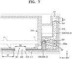
- FIG. 7 illustrates an example of changing a direction in which a movement guide 352a of the toner cartridge 300 of FIG. 5A is formed by extending.
- an angle between a center line S2 of the movement guide 352a and the first direction (y axis) may be smaller than 45 degrees, which is half of the angle formed between the first direction (y axis) and the second direction (z axis).
- the lever unit 350 moves in the second direction (z axis) by the predetermined distance Z1
- the movement pin 331 inserted into the movement guide 352 and the shutter unit 330 in which the movement pin 331 is formed may move in the first direction (y axis) by a distance Y2 different from the predetermined distance Y1.
- the distance Y2 may be greater than the distance Y1.
- a movement distance of the shutter unit 330 may differ according to the direction (or an angle) in which the movement guide 352a is formed by extending.
- the movement distance of the shutter unit 330 in the first direction (y axis) increases, and thus a width D2 of the toner outlet 301 may increase in the first direction (y axis).
- the width D2 of the toner outlet 301 in the first direction (y axis) may be in the range of about 10 mm to about 40 mm.
- the shutter unit 330 when the lever unit 350 is disposed in the reference position 350-1, the shutter unit 330 is disposed in the closing position 330-1, and, when the lever unit 350 is disposed in the pressure position 350-2, the shutter unit 330 is disposed in the opening position 330-2.
- a position relation between the shutter unit 330 and the lever unit 350 is not limited thereto and may be changed as necessary.
- the shutter unit 330 when the lever unit 350 is disposed in the reference position 350-1, the shutter unit 330 is disposed in the opening position 330-2, and, when the lever unit 350 is disposed in the pressure position 350-2, the shutter unit 330 may be disposed in the closing position 330-1.
- FIG. 8 schematically illustrates another example of the toner cartridge 300 of FIG. 4 .
- the toner cartridge 300 includes the container unit 310, a shutter unit 330a, and the lever unit 350.
- the elements other than the shutter unit 330a may be the same as described with reference to FIG. 6B , and thus descriptions thereof are not repeated here.
- the opening 332 is not formed in the shutter unit 330a.
- the movement pin 331 moves in the first direction (y axis) by the movement guide 352 and thus the shutter unit 330a is disposed in the closing position 330-1 such that the toner outlet 301 is blocked. If the external force F1 applied to the lever unit 350 is removed, the lever unit 350 rises and moves to the reference position 350-1, and the shutter unit 330a moves right and is disposed in the opening position 330-2.
- External force may be applied to the lever unit 350 in a direction that is not parallel to the first direction (y axis).
- pressure may be applied to the end portion 351 of the lever unit 350 by the upper cover 102.
- FIG. 9A is a perspective view of the electrophotographic image forming apparatus of FIG. 2 illustrated from a different angle.
- FIG. 9B schematically illustrates a movement of a pressure rod 103 when the upper cover 102 is closed.
- the protruding pressure rod 103 may be formed on the upper cover 102.
- the upper cover 102 is moved such that the opening 101 is closed, and thus the pressure rod 103 is moved toward a hole 302 of the toner cartridge 300.
- a part of the pressure rod 103 is inserted into the hole 302 and contacts the end portion 351 of the lever unit 350.
- the pressure rod 103 contacts the lever unit 350 and applies a pressure thereto when the opening 101 is closed by the upper cover 102.
- FIGS. 10A and 10B illustrate an operating state of the lever unit 350 due to the upper cover 102.
- the lever unit 350 is disposed in the reference position 350-1. If a user closes the upper cover 102, the pressure rod 103 contacts the end portion 351 of the lever unit 350 and applies pressure to the lever unit 350 as illustrated in FIG. 10B . Accordingly, the external force F1 is applied to the lever unit 350.
- the lever unit 350 moves from the reference position 350-1 to the pressure position 350-2 in the second direction (z axis) due to the external force F1.
- the shutter unit 330 connected to the lever unit 350 moves from the closing position 330-1 (see, for example, FIG. 6A ) to the opening position 330-2 (see, for example, FIG. 6B ).
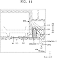
- FIG. 11 schematically illustrates another example of the toner cartridge 300 of FIG. 4 .
- An example of applying the external force F2 to the end portion 351a of the lever unit 350a in the direction A2 opposite to the direction A1 in which the toner cartridge 300 is mounted in the body 100 is described below with reference to FIG. 11 .
- the toner cartridge 300 includes the container unit 310, the shutter unit 330a, and the lever unit 350a.
- the shutter unit 330a and the container unit 310 may be the same as those described with reference to FIG. 8 .
- the lever unit 350a may be different from that described with reference to FIG. 8 .
- the same reference numerals denote the same elements between FIGS. 8 and 11 , and thus redundant descriptions are not repeated.
- the end portion 351a of the lever unit 350a protrudes in the direction A1 in which the toner cartridge 300 is mounted in the body 100.
- the protruding end portion 351a may be exposed to the outside of the toner cartridge 300 as illustrated in FIG. 11 .
- an arrangement of the end portion 351a of the lever unit 350 is not limited thereto.
- the end portion 351a may not be exposed to the outside of the toner cartridge 300.
- the toner cartridge 300 approaches the body 100 in the direction A1 in which the toner cartridge 300 is mounted in the body 100.
- An interference member 104 may be formed in the body 100 and may restrict a movement of the lever unit 350a of the toner cartridge 300 when mounting the toner cartridge 300 in the body 100.
- the interference member 104 may protrude in the direction A2 in which the toner cartridge 300 is removed from the body 100.
- the lever unit 350a may be disposed in the reference position 350-1, and the shutter unit 330a is disposed in the closing position 330-1 before contacting the interference member 104 of the body 100.
- the end portion 351a of the lever unit 350a contacts the interference member 104.
- the lever unit 350a moves in the direction A2 opposite to the direction A1 in which the toner cartridge 300 is mounted in the body 100 due to the interference member 104 and is disposed in the pressure position 350-2.
- the movement pin 331 inserted into the movement guide 352 moves right in the first direction (y axis).
- the shutter unit 330a moves right in the first direction (y axis) and is disposed in the opening position 330-2.
- the process of closing the upper cover 102 or the process of mounting the toner cartridge 300 is described but is not necessarily limited thereto.
- the user may apply pressure to the lever unit 350 by directly applying pressure to the lever unit 350.
- the shutter unit 330 and the lever unit 350 may be connected to each other by the movement pin 331 and the movement guide 352 in the toner cartridge 300.
- a connection structure between the shutter unit 330 and the lever unit 350 is not limited thereto, and may be modified in various ways.
- a bendable bendable member 370 illustrated in FIG. 12 may be disposed between the shutter unit 330 and the lever unit 350.
- FIG. 12 is a schematic perspective view of the bendable member 370 disposed between the shutter unit 330 and the lever unit 350.
- one end 371 of the bendable member 370 may be connected to the shutter unit 330, and another end 372 thereof is connected to the lever unit 350.
- the bendable member 370 may be bent from the first direction (y axis) toward the second direction (z axis). At least a partial region FR of the bendable member 370 is bent, and thus the bendable member 370 connects the shutter unit 330 disposed in the first direction (y axis) and the lever unit 350 disposed in the second direction (z axis).
- the bendable member 370 is divided into the shutter unit 330 and the lever unit 350 according to dotted lines for convenience of description, the bendable member 370 may be separate from the shutter unit 330 and the lever unit 350 or may be integrally formed with at least one of the shutter unit 330 and the lever unit 350.
- the bendable member 370 may be bent according to a characteristic of a material or a structure which forms the bendable member 370.
- the bendable member 370 may be formed of an elastic material, may be a thin plate having a predetermined thickness or less, or may have a structure in which a plurality of grooves are arranged in a length direction.
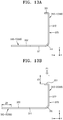
- FIGS. 13A and 13B illustrate an operating state of the bendable member 370 when the external force F1 is applied to the lever unit 350 of FIG. 12 .
- FIG. 13A illustrates the operating state of the bendable member 370 before the external force F1 is applied to the end portion 351 of the lever unit 350.
- FIG. 13B illustrates the operating state of the bendable member 370 after the external force F1 is applied to the end portion 351 of the lever unit 350.
- the lever unit 350 moves in the second direction (z axis) from the reference position 350-1 to the pressure position 350-2.
- the shutter unit 330 is connected to the lever unit 350 via the bendable member 370, and thus, when the lever unit 350 moves in the second direction (z axis) by a movement distance Z3, the shutter unit 330 moves in the first direction (y axis) by the movement distance Z3. Accordingly, the shutter unit 330 moves in the first direction (y axis) from the closing position 330-1 to the opening position 330-2.
- a relative position of the bent region FR of the bendable member 350 varies with respect to the shutter unit 330 and the lever unit 350.
- a distance between the lever unit 350 and the bent region FR in the reference position 350-1 and a distance between the lever unit 350 and the bent region FR in the pressure position 350-2 may vary.
- a rotation member 380 illustrated in FIGS. 14A and 14B that contacts the shutter unit 330 and the lever unit 350 may be further provided.
- FIG. 14A schematically illustrates the shutter unit 330 and the lever unit 350 that are connected to each other by the rotation member 380.
- the rotation member 380 contacts the shutter unit 330 and the lever unit 350, converts force that is applied to the lever unit 350 in the second direction (z axis) into force that is applied to the lever unit 350 in the first direction (y axis) perpendicular to the second direction (z axis), and transfers the force to the shutter unit 330.
- a groove g1 corresponding to a protrusion 381 formed on an outer circumference surface of the rotation member 380 may be formed in the lever unit 350, and a groove g2 corresponding to a protrusion 382 formed on the outer circumference surface of the rotation member 380 may be formed in the shutter unit 330.
- FIG. 14B illustrates an operating state of the lever unit 350, the rotation member 381, and the shutter unit 330 after the external force F1 is applied to the end portion 351 of the lever unit 350 of FIG. 14A .
- the lever unit 350 moves from the reference position 350-1 to the pressure position 350-2 in the second direction (z axis) by a predetermined distance Z4.
- the rotation member 380 that contacts the lever unit 350 rotates in a clockwise direction due to the movement of the lever unit 350.
- the shutter unit 330 that contacts the rotation member 380 moves left in the first direction (y axis).
- the shutter unit 330 moves from the closing position 330-1 to the opening position 330-2 due to the movement of the lever unit 350 by the predetermined distance Z4.
- the movement distance Z4 of the lever unit 350 may be the same as a movement distance Y4 of the shutter unit 330.
- the lever unit 350 rises in the second direction (z axis) and moves from the pressure position 350-2 to the reference position 350-1.
- the rotation member 380 that contacts the lever unit 350 rotates in a counterclockwise direction due to the movement of the lever unit 350.
- the shutter unit 330 that contacts the rotation member 380 moves right in the first direction (y axis). Accordingly, the shutter unit 330 moves from the opening position 330-2 to the closing position 330-1.
- rotation member 380 may be provided in an embodiment, the present invention is not limited thereto.
- a plurality of the rotation members 380 may be provided.
- the movement distance Z4 of the lever unit 350 and the movement distance Y4 of the shutter unit 330 may be differently set according to the gear ratios of the plurality of rotation members 380 that contact the shutter unit 330 and the lever unit 350.
- a method of mounting the toner cartridge 300 in the body 100 after mounting the toner cartridge 300 in the development cartridge 200 i.e., an indirect mounting method
- the method of mounting the toner cartridge 300 in the body 100 is not limited thereto.
- the toner cartridge 300 may be directly mounted in the body 100.
- the development cartridge 200 a process cartridge in which a photoconductive unit including the photoconductive drum 1 and a development unit including the development roller 4 are integrally formed is explained in the above-described embodiment, the scope of the present invention is not limited thereto.
- the development cartridge 200 according to the present invention may be applied to a structure in which the photoconductive unit and the development unit are separate from each other.
Landscapes
- Physics & Mathematics (AREA)
- General Physics & Mathematics (AREA)
- Dry Development In Electrophotography (AREA)
- Electrophotography Configuration And Component (AREA)
Description
- One or more embodiments relate to a cartridge unit that is detachably mounted in an electrophotographic image forming apparatus to supply toner, and an electrophotographic image forming apparatus including the cartridge unit.
- An image forming apparatus using electrophotography prints an image on a recording medium by supplying toner to an electrostatic latent image formed on a photoreceptor to form a visible toner image on the photoreceptor, transferring the visible toner image to the recording medium, and fusing the transferred visible toner image on the recording medium.
- An electrophotographic image forming apparatus includes a development cartridge (or a process cartridge) that develops the visible toner image on the photoreceptor and a toner cartridge that contains toner that is to be supplied to the development cartridge. The toner cartridge may be detachable from the electrophotographic image forming apparatus. When the toner contained in the toner cartridge is completely consumed, the toner cartridge may be replaced with a new toner cartridge.
- The toner cartridge may include a toner outlet that discharges the toner and a shutter that opens and closes the toner outlet to prevent the toner from being discharged from the toner outlet during a replacement process.
- When the toner cartridge is mounted in a direction parallel to a width direction of the recording medium when mounting the toner cartridge, the shutter may be designed to operate in a direction parallel to the direction in which the toner cartridge is mounted.
- However, when the direction in which the toner cartridge is mounted is not parallel to the direction in which the shutter operates, the operating structure of the shutter may be complex. When the toner cartridge is reduced in size, the operating structure of the shutter may become even more complex.
EP 2 290 461 A2EP 0374 920 A2 ,US 2009/129824 A1 ,US 2013/243445 A1 andJP 2008/052033 - The invention is defined by the appended claims.
- These and/or other aspects will become apparent and more readily appreciated from the following description of the embodiments, taken in conjunction with the accompanying drawings in which:
-
FIG. 1 is a schematic view of an electrophotographic image forming apparatus according to an embodiment; -
FIG. 2 is a schematic perspective view of an electrophotographic image forming apparatus, wherein a development cartridge and a toner cartridge are removed from a body, according to an embodiment; -
FIG. 3A is a perspective view of an exemplary development cartridge and toner cartridge, andFIG. 3B is a perspective view of an exemplary toner cartridge separated from a toner cartridge; -
FIG. 4 is a cross-sectional view of a development cartridge and the toner cartridge ofFIG. 3A along line IV-IV; -
FIG. 5A is a cross-sectional view of a part of the toner cartridge ofFIG. 4 , andFIG. 5B is a right lateral view ofFIG. 5A ; -
FIGS. 6A and6B illustrate exemplary operating states of a lever unit and a shutter unit when an external force is applied to the lever unit of the toner cartridge ofFIG. 5A ; -
FIG. 7 illustrates an example of changing a direction in which a movement guide of the toner cartridge ofFIG. 5A is formed and extends; -
FIG. 8 schematically illustrates an exemplary toner cartridge ofFIG. 4 ; -
FIG. 9A is a perspective view of an electrophotographic image forming apparatus ofFIG. 2 , andFIG. 9B schematically illustrates an exemplary movement of a pressure rod according to a closing operation of an upper cover; -
FIGS. 10A and10B illustrate an exemplary operating state of a lever unit due to an upper cover; -
FIG. 11 schematically illustrates an exemplary toner cartridge ofFIG. 4 ; -
FIG. 12 is a schematic perspective view of a bendable member disposed between a shutter unit and a lever unit; -
FIGS. 13A and 13B illustrate an exemplary operating state of a bendable member when external force is applied to the lever unit ofFIG. 12 ; and -
FIG. 14A schematically illustrates a shutter unit and a lever unit that are connected to each other by a rotation member, andFIG. 14B illustrates an operating state of a lever unit, the rotation member, and a shutter unit after external force is applied to an end portion of the lever unit ofFIG. 14A . - Reference will now be made in detail to embodiments, examples of which are illustrated in the accompanying drawings, wherein like reference numerals refer to like elements throughout. Exemplary embodiments may have different forms and should not be construed as being limited to the descriptions set forth herein. Accordingly, the embodiments are described below, by referring to the figures, to explain aspects of the description. Expressions such as "at least one of," when preceding a list of elements, modify the entire list of elements and do not modify the individual elements of the list.
-
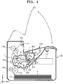
FIG. 1 is a schematic view of an electrophotographic image forming apparatus according to an embodiment.FIG. 2 is a schematic perspective view of the electrophotographic image forming apparatus ofFIG. 1 , wherein adevelopment cartridge 200 and atoner cartridge 300 are removed from abody 100, according to an embodiment. - Referring to
FIGS. 1 and2 , the electrophotographic image forming apparatus includes thebody 100, thedevelopment cartridge 200, and thetoner cartridge 300. Thebody 100 includes anopening 101 providing a passage for mounting and removing thedevelopment cartridge 200 and thetoner cartridge 300 in respective directions A1 and A2. A cover, for example, anupper cover 102 closes or opens the opening 101. Thebody 100 includes anexposure unit 110, atransfer roller 120, and afusing unit 130. Thebody 100 includes a recording medium transfer structure to load and transfer a recording medium P on which an image is to be formed. - The
development cartridge 200 includes aphotoconductive drum 1. Thephotoconductive drum 1 is an example of a photoreceptor, wherein an electrostatic latent image is formed on a surface thereof, and may include a conductive metal pipe and a photosensitive layer around the conductive metal pipe. Acharging roller 2 is an example of a charger for charging thephotoconductive drum 1 to have a uniform surface potential. A charging brush or a corona charger may be used instead of thecharging roller 2. Acleaning blade 8 is an example of a cleaning unit for removing toner and foreign materials on a surface of thephotoconductive drum 1 after a transfer process described later. A cleaning apparatus having another shape, such as a rotating brush, may be used instead of thecleaning blade 8. The toner and foreign materials removed by thecleaning blade 8 may be collected in a waste toner container 9. - A development roller 4 may be used to supply the toner in the
toner cartridge 300 to thephotoconductive drum 1. A development bias voltage may be applied to the development roller 4.Transport members 5 transport the toner supplied from thetoner cartridge 300 to the development roller 4. - The
toner cartridge 300 supplies the toner contained therein to thedevelopment cartridge 200. Thetoner cartridge 300 includes atoner outlet 301. Thedevelopment cartridge 200 includes atoner inlet 201. Thedevelopment cartridge 200 and thetoner cartridge 300 may be mounted in thebody 100 to which thetoner outlet 301 and thetoner inlet 201 are connected. Theupper cover 102 may be used to open and close theopening 101. - The
toner cartridge 300 includes a transportingmember 6 and anagitator 7. Thetransport member 6 transports the toner to thetoner outlet 301. Theagitator 7 stirs the toner and moves the toner toward thetransport member 6. A one-component contact development method may be used in an exemplary embodiment, however, an exemplary embodiment is not limited thereto. A development method using plural components, e.g., a two-component development method may be employed. - The
exposure unit 110 forms the electrostatic latent image on thephotoconductive drum 1 by irradiating light modulated according to image information onto thephotoconductive drum 1. Theexposure unit 110 may be a laser scanning unit (LSU) using a laser diode as a light source, or a light-emitting diode (LED) exposure unit using an LED as a light source. - The
transfer roller 120 is an example of a transfer unit for transferring a toner image from thephotoconductive drum 1 to the recording medium P. A transfer bias voltage for transferring the toner image to the recording medium P is applied to thetransfer roller 120. A transfer belt, a corona transfer unit or a transfer unit using a pin scorotron method may be used instead of thetransfer roller 120. - The recording media P may be picked up, e.g., one-by-one from a
loading tray 141 by apickup roller 142, and transferred to a region where thephotoconductive drum 1 and thetransfer roller 120 may face each other by afeed roller 143. - The
fusing unit 130 applies heat and pressure to an image transferred to the recording medium P so as to fuse the image onto the recording medium P. The recording medium P that passed through thefusing unit 130 may be discharged outside thebody 100 by adischarge roller 146. - According to an exemplary embodiment, the
exposure unit 110 irradiates the light modulated according to the image information onto thephotoconductive drum 1 to develop the electrostatic latent image. The development roller 4 supplies the toner to the electrostatic latent image to form the visible toner image on the surface of thephotoconductive drum 1. The recording medium loaded in theloading tray 141 may be transferred to the region where thephotoconductive drum 1 and thetransfer roller 120 face each other by thepickup roller 142 and thefeed roller 143, and the toner image may be transferred to the recording medium P from thephotoconductive drum 1 according to the transfer bias voltage applied to thetransfer roller 120. After the recording medium P passes through thefusing unit 130, the toner image may be used onto the recording medium P according to heat and pressure. After the fusing, the recording medium P may be discharged by thedischarge roller 146. - The
development cartridge 200 and thetoner cartridge 300 are consumable products that may be replaced, for example, after their lifespan is expired. Accordingly, thedevelopment cartridge 200 and thetoner cartridge 300 may be detachably installed in thebody 100. For example, as illustrated inFIG. 2 , thedevelopment cartridge 200 and thetoner cartridge 300 may be mounted and removed, for example, in the respective directions A1 and A2, which are directions that cross a length direction (y axis) of the transfer roller 120 (see, for example,FIG. 1 ) formed in thebody 100. Thedevelopment cartridge 200 and thetoner cartridge 300 may be mounted in, and removed from, thebody 100 via theopening 101 formed in thebody 100. Theopening 101 may be opened and closed by theupper cover 102. - Lifespan of the
development cartridge 200 and thetoner cartridge 300 may be different, and thus thedevelopment cartridge 200 and thetoner cartridge 300 may be individually replaced.FIG. 3A is an exemplary perspective view of thedevelopment cartridge 200 and thetoner cartridge 300 ofFIG. 2 .FIG. 3B is a perspective view of thetoner cartridge 300 separated from thedevelopment cartridge 200 ofFIG. 3A . Referring toFIGS. 3A and3B , thedevelopment cartridge 200 includes aninsertion part 202 into which thetoner cartridge 300 may be inserted. Theinsertion part 202 may be formed extending in a length direction (y axis) of thedevelopment cartridge 200. A cross-sectional shape of theinsertion part 202 in a direction perpendicular to the length direction (y axis) may correspond to a cross-sectional shape of thetoner cartridge 300 in the direction perpendicular to the length direction (y axis). Thetoner cartridge 300 may be inserted into, or removed from, theinsertion part 202 such that thetoner cartridge 300 may be mounted in or removed from thedevelopment cartridge 200 in a direction parallel to the length direction (y axis) of thedevelopment cartridge 200. When thetoner cartridge 300 is mounted in thedevelopment cartridge 200, thedevelopment cartridge 200 is mounted in, or removed from, thebody 100 as illustrated inFIG. 2 , and thus thetoner cartridge 300 may be mounted in or removed from thebody 100. - The
toner cartridge 300 may be mounted in, or removed from, thebody 100 in the same direction A1 or A2 as the direction in which thedevelopment cartridge 200 is mounted in, or removed from, thebody 100, and may be mounted in, or removed from, thedevelopment cartridge 200 in a different direction (y axis) from the direction A1 or A2 in which thedevelopment cartridge 200 is mounted in or removed from thebody 100. -
FIG. 4 is a cross-sectional view of thedevelopment cartridge 200 and thetoner cartridge 300 ofFIG. 3A taken along line IV-IV. Referring toFIG. 4 , thetoner cartridge 300 may be mounted in thedevelopment cartridge 200 so that thetoner inlet 201 and thetoner outlet 301 are positioned to correspond to each other. Ashutter unit 330 may be movably disposed in thetoner outlet 301. Opening and closing of thetoner outlet 301 may be determined by theshutter unit 330. For example, theshutter unit 330 may be movable in a direction parallel to the length direction (y axis) of thedevelopment cartridge 200 between an opening position in which thetoner outlet 301 is opened and a closing position in which thetoner outlet 301 is closed. - A structure for operating the
shutter unit 330 may restrict movement of theshutter unit 330 by a predetermined region of thedevelopment cartridge 200 such that theshutter unit 330 moves relative to thetoner outlet 301 when mounting thetoner cartridge 300 in thedevelopment cartridge 200. However, such a structure may restrict a degree of design freedom such that the movement of theshutter unit 330 may be restricted from moving in a direction parallel to a direction in which thetoner cartridge 300 is mounted. Such a structure may make it difficult to move theshutter unit 330 by a sufficient movement distance upon thetoner cartridge 300 being small in size. - The electrophotographic image forming apparatus of an exemplary embodiment has a
shutter unit 330 that is simple in structure and flexible in design. As an example, the electrophotographic image forming apparatus of an exemplary embodiment has a structure in which a cartridge unit that is detachably mounted in thebody 100, for example, theshutter unit 330 of thetoner cartridge 300, is movable in a direction that crosses a direction in which an external force is applied to the cartridge unit. As an example of the cartridge unit, anexemplary toner cartridge 300 is described below. However, the cartridge unit is not limited to thetoner cartridge 300 and may be thedevelopment cartridge 200 or another element that may be detachably mounted in thebody 100. -
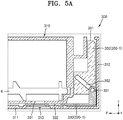
FIG. 5A is a cross-sectional view of a part of thetoner cartridge 300 ofFIG. 4 , andFIG. 5B is a right lateral view ofFIG. 5A . InFIG. 5B , asecond plate 312 is illustrated in a two-dot chain line for convenience of illustration, so as to clearly illustrate theshutter unit 330 and alever unit 350. - Referring to
FIG. 5A , thetoner cartridge 300 includes acontainer unit 310 that contains toner therein and in which thetoner outlet 301 may be formed, theshutter unit 330 that opens and closes thetoner outlet 301, and thelever unit 350 that is connected to theshutter unit 330 and moves theshutter unit 330. - The
container unit 310 includes a space for containing the toner. Thetransport member 6 for transporting the toner is installed in the space. The toner transported by thetransport member 6 may be discharged via thetoner outlet 301. - The
shutter unit 330 may be installed in thetoner outlet 301 and is movable in a length direction (hereinafter referred to as a "first direction (y axis)") of thetoner cartridge 300. Anopening 332 corresponding to thetoner outlet 301 may be formed in theshutter unit 330. When theshutter unit 330 rectilinearly moves left in the first direction (y axis) so that theopening 332 overlaps with thetoner outlet 301, the toner is discharged to the outside via thetoner outlet 301. A position of theshutter unit 330 may define an opening position 330-2 (see, for example,FIG. 6B ). When theshutter unit 330 rectilinearly moves right in the first direction (y axis) so that theopening 332 does not overlap with thetoner outlet 301, discharge of the toner to the outside is prevented. A position of theshutter unit 330 may define a closing position 330-1. - A
first plate 311 may be disposed in a lower portion of theshutter unit 330. Thefirst plate 311 guides movement of theshutter unit 330 in the first direction (y axis) and restricts movement of theshutter unit 330 in a second direction (z axis). Anoutlet 313 may be formed at a position on thefirst plate 311 corresponding to thetoner outlet 301. When theshutter unit 330 is in the opening position 330-2, thetoner outlet 301, theopening 332, and theoutlet 313 overlap with each other, and thus the toner contained in thetoner cartridge 300 may be discharged to the outside. The discharged toner may be injected into the toner inlet 201 (see, for example,FIG. 4 ) of thedevelopment cartridge 200 ofFIG. 1 . - The
lever unit 350 may be connected to theshutter unit 330 and transfers external forces applied in a direction that crosses the first direction (y axis) to theshutter unit 330. - As an example of a connection structure of the
lever unit 350 and theshutter unit 330, one of thelever unit 350 and theshutter unit 330 includes amovement pin 331, and the other includes amovement guide 352 that guides movement of themovement pin 331. Referring toFIG. 5A , themovement pin 331 is provided in theshutter unit 330, and themovement guide 352 is provided in thelever unit 350. Themovement pin 331 may be formed separately from theshutter unit 330 but is not limited thereto. Themovement pin 331 may be integrally formed with theshutter unit 330. - The
movement guide 352 may be formed extending in the direction that crosses the first direction (y axis). For example, themovement guide 352 may be formed by extending in a direction that is at an acute angle to the first direction (y axis). Themovement guide 352 may be formed by extending in a direction that crosses the second direction (z axis). For example, themovement guide 352 may be formed by extending in a direction that is at an acute angle to the second direction (z axis). Themovement pin 331 may be inserted into themovement guide 352. In accordance with a movement of thelever unit 350 in which themovement guide 352 is provided, themovement pin 331 inserted into themovement guide 352 moves in the first direction (y axis). Theshutter unit 330 moves in the first direction (y axis) by the movement of themovement pin 331 in the first direction (y axis). - The
lever unit 350 may be movable to the second direction (z axis) that crosses the first direction (y axis). For example, the second direction (z axis) may be perpendicular to the first direction (y axis). The second direction (z axis) may be a direction that crosses a plane (xy plane) on which thetoner outlet 301 is formed. - The
second plate 312 that may be formed in parallel to the second direction (z axis) may be disposed in a side portion of thelevel unit 350. Thesecond plate 312 guides movement of thelevel unit 350 in the second direction (z axis), and restricts movement of thelever unit 350 in the first direction (y axis). - An
end portion 351 of thelever unit 350 may be disposed such that theend portion 351 does not protrude outside of thetoner cartridge 300, which may prevent thelever unit 350 from being unintentionally pressed when mounting thetoner cartridge 300 in thedevelopment cartridge 200 and when mounting thedevelopment cartridge 200, in which thetoner cartridge 300 is mounted, in thebody 100. - Referring to
FIG. 5B , thelever unit 350 may be connected to thecontainer unit 310 by anelastic member 106. One end of theelastic member 106 may be connected to aprotrusion 353 of thelever unit 350, and another end thereof is connected to aprotrusion 105 of thecontainer unit 310. If the external force applied to thelever unit 350 is removed, thelever unit 350 may be restored to a reference position 350-1 by theelastic member 106. A spring may be used as an example of theelastic member 106, but theelastic member 106 is not limited thereto. -
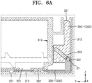
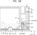
FIGS. 6A and6B conceptually illustrate operating states of thelever unit 350 and theshutter unit 330 when an external force F1 is applied to thelever unit 350 of thetoner cartridge 300 ofFIG. 5A .FIG. 6A illustrates the operating state before the external force F1 is applied to thelever unit 350.FIG. 6B illustrates the operating state after the external force F1 is applied to thelever unit 350. For convenience of illustration, elements other than thelever unit 350 and theshutter unit 330 are illustrated with broken lines. - Referring to
FIG. 6A , before the external force F1 is applied to thelever unit 350, thelever unit 350 may be disposed in the reference position 350-1, and theshutter unit 330 may be disposed in the closing position 330-1. Themovement pin 331 of theshutter unit 330 may be inserted into themovement guide 352 of thelever unit 350. - Referring to
FIG. 6B , if the external force F1 is applied to theend portion 351 of thelever unit 350, pressure is applied to thelever unit 350, thelever unit 350 moves downward by a predetermined distance Z1 in the second direction (z axis), and is disposed in a pressure position 350-2. That is, thelever unit 350 moves from the reference position 350-1 to the pressure position 350-2 in the second direction (z axis) due to the external force F1. When thelever unit 350 moves from the reference position 350-1 to the pressure position 350-2, themovement pin 331 inserted into themovement guide 352 moves in a shape of themovement guide 352. The movement of theshutter unit 330 in the second direction (z axis) may be restricted by thefirst plate 311, and thus themovement pin 331, which is formed in theshutter unit 330, does not move in the second direction (z axis) but rectilinearly moves in the first direction (y axis). Theshutter unit 330 in which themovement pin 331 is formed moves left in the first direction (y axis) by a predetermined distance Y1. Accordingly, theopening 332 of theshutter unit 330 overlaps with thetoner outlet 301 such that toner contained in thecontainer unit 310 is discharged to the outside. The movement distance Y1 of theshutter unit 330 may be the same as, or greater than, a width D1 of thetoner outlet 301 in the first direction (y axis). - The movement distance Y1 of the
shutter unit 330 may be the same as the movement distance Z1 of thelever unit 350. However, the movement distance Y1 of theshutter unit 330 and the movement distance Z1 of thelever unit 350 may be different from each other. A direction in which themovement guide 352 is formed by extending may be changed. A reference numeral S1 denotes a center line of themovement guide 352. -
FIG. 7 illustrates an example of changing a direction in which amovement guide 352a of thetoner cartridge 300 ofFIG. 5A is formed by extending. Referring toFIG. 7 , an angle between a center line S2 of themovement guide 352a and the first direction (y axis) may be smaller than 45 degrees, which is half of the angle formed between the first direction (y axis) and the second direction (z axis). When thelever unit 350 moves in the second direction (z axis) by the predetermined distance Z1, themovement pin 331 inserted into themovement guide 352 and theshutter unit 330 in which themovement pin 331 is formed may move in the first direction (y axis) by a distance Y2 different from the predetermined distance Y1. The distance Y2 may be greater than the distance Y1. Thus, although thelever unit 350 moves by the same distance, a movement distance of theshutter unit 330 may differ according to the direction (or an angle) in which themovement guide 352a is formed by extending. As illustrated inFIG. 7 , the movement distance of theshutter unit 330 in the first direction (y axis) increases, and thus a width D2 of thetoner outlet 301 may increase in the first direction (y axis). For example, the width D2 of thetoner outlet 301 in the first direction (y axis) may be in the range of about 10 mm to about 40 mm. - According to an exemplary embodiment, when the
lever unit 350 is disposed in the reference position 350-1, theshutter unit 330 is disposed in the closing position 330-1, and, when thelever unit 350 is disposed in the pressure position 350-2, theshutter unit 330 is disposed in the opening position 330-2. However, a position relation between theshutter unit 330 and thelever unit 350 is not limited thereto and may be changed as necessary. For example, when thelever unit 350 is disposed in the reference position 350-1, theshutter unit 330 is disposed in the opening position 330-2, and, when thelever unit 350 is disposed in the pressure position 350-2, theshutter unit 330 may be disposed in the closing position 330-1. -
FIG. 8 schematically illustrates another example of thetoner cartridge 300 ofFIG. 4 . Referring toFIG. 8 , thetoner cartridge 300 includes thecontainer unit 310, ashutter unit 330a, and thelever unit 350. The elements other than theshutter unit 330a may be the same as described with reference toFIG. 6B , and thus descriptions thereof are not repeated here. Theopening 332 is not formed in theshutter unit 330a. When the external force F1 is applied to thelever unit 350, thelever unit 350 moves in the second direction (z axis) by the predetermined distance Z1 to the pressure position 350-2 as illustrated inFIG. 8 . Themovement pin 331 moves in the first direction (y axis) by themovement guide 352 and thus theshutter unit 330a is disposed in the closing position 330-1 such that thetoner outlet 301 is blocked. If the external force F1 applied to thelever unit 350 is removed, thelever unit 350 rises and moves to the reference position 350-1, and theshutter unit 330a moves right and is disposed in the opening position 330-2. - External force may be applied to the
lever unit 350 in a direction that is not parallel to the first direction (y axis). As an example, pressure may be applied to theend portion 351 of thelever unit 350 by theupper cover 102. -
FIG. 9A is a perspective view of the electrophotographic image forming apparatus ofFIG. 2 illustrated from a different angle.FIG. 9B schematically illustrates a movement of apressure rod 103 when theupper cover 102 is closed. - Referring to
FIGS. 9A and9B , no external force is applied to theend portion 351 of thelever unit 350 until thedevelopment cartridge 200, in which thetoner cartridge 300 is mounted, is mounted in thebody 100. The protrudingpressure rod 103 may be formed on theupper cover 102. Theupper cover 102 is moved such that theopening 101 is closed, and thus thepressure rod 103 is moved toward ahole 302 of thetoner cartridge 300. A part of thepressure rod 103 is inserted into thehole 302 and contacts theend portion 351 of thelever unit 350. Thepressure rod 103 contacts thelever unit 350 and applies a pressure thereto when theopening 101 is closed by theupper cover 102. -
FIGS. 10A and10B illustrate an operating state of thelever unit 350 due to theupper cover 102. Referring toFIG. 10A , before thepressure rod 103 contacts thelever unit 350, thelever unit 350 is disposed in the reference position 350-1. If a user closes theupper cover 102, thepressure rod 103 contacts theend portion 351 of thelever unit 350 and applies pressure to thelever unit 350 as illustrated inFIG. 10B . Accordingly, the external force F1 is applied to thelever unit 350. Thelever unit 350 moves from the reference position 350-1 to the pressure position 350-2 in the second direction (z axis) due to the external force F1. When thelever unit 350 moves from the reference position 350-1 to the pressure position 350-2, theshutter unit 330 connected to thelever unit 350 moves from the closing position 330-1 (see, for example,FIG. 6A ) to the opening position 330-2 (see, for example,FIG. 6B ). - When the user opens the
upper cover 102, contact of thepressure rod 103 and thelever unit 350 may be released. Accordingly, the external force F1 applied to theend portion 351 of thelever unit 350 is removed, and thelever unit 350 moves from the pressure position 350-2 to the reference position 350-1 due to theelastic member 106. Theshutter unit 330 moves from the opening position 330-2 to the closing position 330-1. Theshutter unit 330, when in the closing position 330-1, prevents toner from being discharged from thetoner outlet 301. - As another example of applying external force to the
lever unit 350 in a direction that crosses the first direction (y axis), theend portion 351 of thelever unit 350 may be pressured by thebody 100 when mounting thetoner cartridge 300 coupled to thedevelopment cartridge 200 in thebody 100. When mounting thetoner cartridge 300 in thebody 100, external force F2 may be applied to anend portion 351a of alever unit 350a in the direction A2 opposite to the direction A1 in which thedevelopment cartridge 200 or thetoner cartridge 300 is mounted in thebody 100. -
FIG. 11 schematically illustrates another example of thetoner cartridge 300 ofFIG. 4 . An example of applying the external force F2 to theend portion 351a of thelever unit 350a in the direction A2 opposite to the direction A1 in which thetoner cartridge 300 is mounted in thebody 100 is described below with reference toFIG. 11 . - The
toner cartridge 300 includes thecontainer unit 310, theshutter unit 330a, and thelever unit 350a. Theshutter unit 330a and thecontainer unit 310 may be the same as those described with reference toFIG. 8 . Thelever unit 350a may be different from that described with reference toFIG. 8 . The same reference numerals denote the same elements betweenFIGS. 8 and11 , and thus redundant descriptions are not repeated. Theend portion 351a of thelever unit 350a protrudes in the direction A1 in which thetoner cartridge 300 is mounted in thebody 100. Theprotruding end portion 351a may be exposed to the outside of thetoner cartridge 300 as illustrated inFIG. 11 . However, an arrangement of theend portion 351a of thelever unit 350 is not limited thereto. Theend portion 351a may not be exposed to the outside of thetoner cartridge 300. - The
toner cartridge 300 approaches thebody 100 in the direction A1 in which thetoner cartridge 300 is mounted in thebody 100. Aninterference member 104 may be formed in thebody 100 and may restrict a movement of thelever unit 350a of thetoner cartridge 300 when mounting thetoner cartridge 300 in thebody 100. Theinterference member 104 may protrude in the direction A2 in which thetoner cartridge 300 is removed from thebody 100. Thelever unit 350a may be disposed in the reference position 350-1, and theshutter unit 330a is disposed in the closing position 330-1 before contacting theinterference member 104 of thebody 100. In this regard, when thetoner cartridge 300 approaches thebody 100 in the direction A1 in which thetoner cartridge 300 is mounted in thebody 100, theend portion 351a of thelever unit 350a contacts theinterference member 104. Thelever unit 350a moves in the direction A2 opposite to the direction A1 in which thetoner cartridge 300 is mounted in thebody 100 due to theinterference member 104 and is disposed in the pressure position 350-2. While thelever unit 350a moves from the reference position 350-1 to the pressure position 350-2, themovement pin 331 inserted into themovement guide 352 moves right in the first direction (y axis). Accordingly, theshutter unit 330a moves right in the first direction (y axis) and is disposed in the opening position 330-2. - As an example of applying the external forces F1 and F2 to the
lever unit 350, the process of closing theupper cover 102 or the process of mounting thetoner cartridge 300 is described but is not necessarily limited thereto. The user may apply pressure to thelever unit 350 by directly applying pressure to thelever unit 350. - The
shutter unit 330 and thelever unit 350 may be connected to each other by themovement pin 331 and themovement guide 352 in thetoner cartridge 300. However, a connection structure between theshutter unit 330 and thelever unit 350 is not limited thereto, and may be modified in various ways. - As another example of the connection structure of the
shutter unit 330 and thelever unit 350, a bendablebendable member 370 illustrated inFIG. 12 may be disposed between theshutter unit 330 and thelever unit 350. -
FIG. 12 is a schematic perspective view of thebendable member 370 disposed between theshutter unit 330 and thelever unit 350. Referring toFIG .12 , oneend 371 of thebendable member 370 may be connected to theshutter unit 330, and anotherend 372 thereof is connected to thelever unit 350. Thebendable member 370 may be bent from the first direction (y axis) toward the second direction (z axis). At least a partial region FR of thebendable member 370 is bent, and thus thebendable member 370 connects theshutter unit 330 disposed in the first direction (y axis) and thelever unit 350 disposed in the second direction (z axis). Although thebendable member 370 is divided into theshutter unit 330 and thelever unit 350 according to dotted lines for convenience of description, thebendable member 370 may be separate from theshutter unit 330 and thelever unit 350 or may be integrally formed with at least one of theshutter unit 330 and thelever unit 350. - The
bendable member 370 may be bent according to a characteristic of a material or a structure which forms thebendable member 370. For example, thebendable member 370 may be formed of an elastic material, may be a thin plate having a predetermined thickness or less, or may have a structure in which a plurality of grooves are arranged in a length direction. -
FIGS. 13A and 13B illustrate an operating state of thebendable member 370 when the external force F1 is applied to thelever unit 350 ofFIG. 12 .FIG. 13A illustrates the operating state of thebendable member 370 before the external force F1 is applied to theend portion 351 of thelever unit 350.FIG. 13B illustrates the operating state of thebendable member 370 after the external force F1 is applied to theend portion 351 of thelever unit 350. - Referring to
FIGS. 13A and 13B , when the external force F1 is applied to theend portion 351 of thelever unit 350, thelever unit 350 moves in the second direction (z axis) from the reference position 350-1 to the pressure position 350-2. Theshutter unit 330 is connected to thelever unit 350 via thebendable member 370, and thus, when thelever unit 350 moves in the second direction (z axis) by a movement distance Z3, theshutter unit 330 moves in the first direction (y axis) by the movement distance Z3. Accordingly, theshutter unit 330 moves in the first direction (y axis) from the closing position 330-1 to the opening position 330-2. While thelever unit 350 moves between positions, a relative position of the bent region FR of thebendable member 350 varies with respect to theshutter unit 330 and thelever unit 350. For example, a distance between thelever unit 350 and the bent region FR in the reference position 350-1 and a distance between thelever unit 350 and the bent region FR in the pressure position 350-2 may vary. - As another example of a connection structure of the
shutter unit 330 and thelever unit 350, arotation member 380 illustrated inFIGS. 14A and 14B that contacts theshutter unit 330 and thelever unit 350 may be further provided. -
FIG. 14A schematically illustrates theshutter unit 330 and thelever unit 350 that are connected to each other by therotation member 380. Referring toFIG. 14A , therotation member 380 contacts theshutter unit 330 and thelever unit 350, converts force that is applied to thelever unit 350 in the second direction (z axis) into force that is applied to thelever unit 350 in the first direction (y axis) perpendicular to the second direction (z axis), and transfers the force to theshutter unit 330. As an example, a groove g1 corresponding to aprotrusion 381 formed on an outer circumference surface of therotation member 380 may be formed in thelever unit 350, and a groove g2 corresponding to a protrusion 382 formed on the outer circumference surface of therotation member 380 may be formed in theshutter unit 330. -
FIG. 14B illustrates an operating state of thelever unit 350, therotation member 381, and theshutter unit 330 after the external force F1 is applied to theend portion 351 of thelever unit 350 ofFIG. 14A . Referring toFIG .14B , when the external force F1 is applied, thelever unit 350 moves from the reference position 350-1 to the pressure position 350-2 in the second direction (z axis) by a predetermined distance Z4. Therotation member 380 that contacts thelever unit 350 rotates in a clockwise direction due to the movement of thelever unit 350. Theshutter unit 330 that contacts therotation member 380 moves left in the first direction (y axis). Accordingly, theshutter unit 330 moves from the closing position 330-1 to the opening position 330-2 due to the movement of thelever unit 350 by the predetermined distance Z4. The movement distance Z4 of thelever unit 350 may be the same as a movement distance Y4 of theshutter unit 330. - If the external force F1 applied to the
end portion 351 of thelever unit 350 is removed, thelever unit 350 rises in the second direction (z axis) and moves from the pressure position 350-2 to the reference position 350-1. Therotation member 380 that contacts thelever unit 350 rotates in a counterclockwise direction due to the movement of thelever unit 350. Theshutter unit 330 that contacts therotation member 380 moves right in the first direction (y axis). Accordingly, theshutter unit 330 moves from the opening position 330-2 to the closing position 330-1. - Although a
single rotation member 380 may be provided in an embodiment, the present invention is not limited thereto. A plurality of therotation members 380 may be provided. The movement distance Z4 of thelever unit 350 and the movement distance Y4 of theshutter unit 330 may be differently set according to the gear ratios of the plurality ofrotation members 380 that contact theshutter unit 330 and thelever unit 350. - In the above-described embodiment, a method of mounting the
toner cartridge 300 in thebody 100 after mounting thetoner cartridge 300 in thedevelopment cartridge 200, i.e., an indirect mounting method, is explained. However, the method of mounting thetoner cartridge 300 in thebody 100 is not limited thereto. Thetoner cartridge 300 may be directly mounted in thebody 100. - Although, as an example of the
development cartridge 200, a process cartridge in which a photoconductive unit including thephotoconductive drum 1 and a development unit including the development roller 4 are integrally formed is explained in the above-described embodiment, the scope of the present invention is not limited thereto. For example, thedevelopment cartridge 200 according to the present invention may be applied to a structure in which the photoconductive unit and the development unit are separate from each other. - It should be understood that the exemplary embodiments described therein should be considered in a descriptive sense only and not for purposes of limitation.
- While one or more embodiments have been described with reference to the figures, it will be understood by those of ordinary skill in the art that various changes in form and details may be made therein without departing from the scope as defined by the following claims.
Claims (10)
- A cartridge unit (300) adapted to be detachably mounted to an electrophotographic image forming apparatus comprising:a container unit (310) including a first opening (301);a shutter unit (330) including a second opening (332), the shutter unit (330) linearly movable in a first direction between an opening position in which at least a part of the second opening (332) overlaps with the first opening (301) to open the first opening (301) and a closing position in which the second opening (332) does not overlap with the first opening (301) to close the first opening (301); anda lever unit (350) movable in a second direction that is not parallel with the first direction, and connected to the shutter unit (330) such that the shutter unit (330) moves in the first direction if the lever unit (350) moves in the second direction.
- The cartridge unit of claim 1, wherein, if an external force is applied to the lever unit (350), the lever unit (350) moves in the second direction from a reference position that is a position before the external force is applied to the lever unit (350) to a pressure position that is a position after the external force is applied to the lever unit (350).
- The cartridge unit of claim 2, wherein, if the lever unit (350) moves from the reference position to the pressure position, the shutter unit (330) linearly moves from a closing position to an opening position.
- The cartridge unit of claim 2, wherein a movement distance of the lever unit (350) from the reference position to the pressure position is different from a movement distance of the shutter unit (330) between the closing position and the opening position.
- The cartridge unit of claim 2, wherein a movement distance of the lever unit (350) from the reference position to the pressure position is the same as a movement distance of the shutter unit (330) between the closing position and the opening position.
- The cartridge unit of claim 1, wherein one of the shutter unit (330) and the lever unit (350) comprises a movement portion (331), and the other comprises a guide (352) configured to guide a movement of the movement portion (331).
- The cartridge unit of claim 1, wherein an end portion of the lever unit (350) is adapted to receive an external force so as to move the lever unit (350) in the second direction, the end portion is disposed so as not to protrude outside the cartridge unit.
- The cartridge unit of claim 1, wherein the lever unit (350) is linearly movable in the second direction.
- The cartridge unit of claim 1, wherein the lever unit (350) is movable in the second direction that crosses the first direction.
- An electrophotographic image forming apparatus comprising:a body (100) comprising a body opening (101) and a cover (102) which opens and closes the body opening (101); andthe cartridge unit (300) of any preceding claim.
Applications Claiming Priority (2)
| Application Number | Priority Date | Filing Date | Title |
|---|---|---|---|
| KR1020140019693A KR20150098421A (en) | 2014-02-20 | 2014-02-20 | Cartridge unit and electrophotographic image forming apparatus having the same |
| EP15152004.6A EP2911005B1 (en) | 2014-02-20 | 2015-01-21 | Cartridge unit and electrophotographic image forming apparatus including the same |
Related Parent Applications (2)
| Application Number | Title | Priority Date | Filing Date |
|---|---|---|---|
| EP15152004.6A Division EP2911005B1 (en) | 2014-02-20 | 2015-01-21 | Cartridge unit and electrophotographic image forming apparatus including the same |
| EP15152004.6A Division-Into EP2911005B1 (en) | 2014-02-20 | 2015-01-21 | Cartridge unit and electrophotographic image forming apparatus including the same |
Publications (2)
| Publication Number | Publication Date |
|---|---|
| EP3220201A1 EP3220201A1 (en) | 2017-09-20 |
| EP3220201B1 true EP3220201B1 (en) | 2021-10-27 |
Family
ID=52354883
Family Applications (2)
| Application Number | Title | Priority Date | Filing Date |
|---|---|---|---|
| EP17160925.8A Active EP3220201B1 (en) | 2014-02-20 | 2015-01-21 | Cartridge unit and electrophotographic image forming apparatus including the same |
| EP15152004.6A Active EP2911005B1 (en) | 2014-02-20 | 2015-01-21 | Cartridge unit and electrophotographic image forming apparatus including the same |
Family Applications After (1)
| Application Number | Title | Priority Date | Filing Date |
|---|---|---|---|
| EP15152004.6A Active EP2911005B1 (en) | 2014-02-20 | 2015-01-21 | Cartridge unit and electrophotographic image forming apparatus including the same |
Country Status (5)
| Country | Link |
|---|---|
| US (2) | US9417560B2 (en) |
| EP (2) | EP3220201B1 (en) |
| KR (1) | KR20150098421A (en) |
| CN (1) | CN204536731U (en) |
| WO (1) | WO2015126038A1 (en) |
Families Citing this family (3)
| Publication number | Priority date | Publication date | Assignee | Title |
|---|---|---|---|---|
| JP6390564B2 (en) * | 2015-09-11 | 2018-09-19 | 京セラドキュメントソリューションズ株式会社 | Image forming apparatus |
| US20180310236A1 (en) * | 2017-04-20 | 2018-10-25 | Qualcomm Incorporated | Multi-subscriber identity module card user equipment with subscriber selection |
| JP7000730B2 (en) * | 2017-08-01 | 2022-01-19 | ブラザー工業株式会社 | Drum unit and image forming device |
Family Cites Families (22)
| Publication number | Priority date | Publication date | Assignee | Title |
|---|---|---|---|---|
| JPS6314187A (en) * | 1986-07-04 | 1988-01-21 | Sharp Corp | Developer recovering device |
| US5128724A (en) | 1988-12-23 | 1992-07-07 | Casio Computer Co., Ltd. | Developer restoring unit in an image forming apparatus |
| US6763215B1 (en) * | 2001-06-27 | 2004-07-13 | Nu-Kote International, Inc. | Toner cartridge or cassette open/closure apparatus |
| KR100541959B1 (en) * | 2004-07-22 | 2006-01-10 | 삼성전자주식회사 | Fitting protecting apparatus of developer cartridge and image forming apparatus having the same |
| JP4802845B2 (en) * | 2006-04-25 | 2011-10-26 | 村田機械株式会社 | Image forming apparatus |
| JP2008052033A (en) | 2006-08-24 | 2008-03-06 | Canon Inc | Image forming apparatus |
| KR101347158B1 (en) * | 2007-01-29 | 2014-01-03 | 삼성전자주식회사 | Image forming apparatus having Toner path opening and closing apparatus |
| US7831190B2 (en) | 2007-07-04 | 2010-11-09 | Samsung Electronics Co., Ltd. | Cover opening and closing unit, image forming apparatus having the same, and method of removing and mounting cover |
| JP4440298B2 (en) * | 2007-11-19 | 2010-03-24 | シャープ株式会社 | Toner conveying device and image forming apparatus |
| KR100912900B1 (en) * | 2008-02-22 | 2009-08-20 | 삼성전자주식회사 | Developer cartrage, developing device and image forming apparatus having the same |
| JP2010054638A (en) * | 2008-08-27 | 2010-03-11 | Sharp Corp | Toner conveying unit and image forming apparatus having the same |
| JP2010054755A (en) * | 2008-08-28 | 2010-03-11 | Sharp Corp | Toner conveying device and image forming apparatus using the same |
| JP5286175B2 (en) * | 2009-06-30 | 2013-09-11 | 京セラドキュメントソリューションズ株式会社 | Developer cartridge |
| KR101608062B1 (en) * | 2009-08-28 | 2016-03-31 | 삼성전자주식회사 | Detachable toner cartridge and image forming apparatus having the same |
| EP2381317A1 (en) * | 2010-04-21 | 2011-10-26 | Kabushiki Kaisha Toshiba | Toner cartridge and image forming apparatus |
| JP5056912B2 (en) * | 2010-06-30 | 2012-10-24 | ブラザー工業株式会社 | Image forming apparatus and toner cartridge |
| JP5182342B2 (en) * | 2010-09-07 | 2013-04-17 | ブラザー工業株式会社 | Development device |
| US8948616B2 (en) | 2010-11-03 | 2015-02-03 | Kabushiki Kaisha Toshiba | Image forming apparatus to discriminate toner cartridge |
| JP5614251B2 (en) * | 2010-11-10 | 2014-10-29 | 富士ゼロックス株式会社 | Developer container and image forming apparatus |
| US8867968B2 (en) * | 2011-12-30 | 2014-10-21 | Lexmark International, Inc. | Movable toner port cover member for a replaceable unit of an imaging device |
| JP5953841B2 (en) | 2012-03-13 | 2016-07-20 | 株式会社リコー | Image forming apparatus |
| JP6116373B2 (en) * | 2013-05-27 | 2017-04-19 | キヤノン株式会社 | Developer container, developing device, developer supply device, process cartridge, image forming apparatus |
-
2014
- 2014-02-20 KR KR1020140019693A patent/KR20150098421A/en not_active Application Discontinuation
- 2014-11-20 WO PCT/KR2014/011159 patent/WO2015126038A1/en active Application Filing
- 2014-11-21 US US14/550,177 patent/US9417560B2/en active Active
-
2015
- 2015-01-21 EP EP17160925.8A patent/EP3220201B1/en active Active
- 2015-01-21 EP EP15152004.6A patent/EP2911005B1/en active Active
- 2015-02-13 CN CN201520107766.XU patent/CN204536731U/en active Active
-
2016
- 2016-07-06 US US15/202,626 patent/US9778595B2/en active Active
Also Published As
| Publication number | Publication date |
|---|---|
| US9778595B2 (en) | 2017-10-03 |
| EP2911005A1 (en) | 2015-08-26 |
| US20150234320A1 (en) | 2015-08-20 |
| EP2911005B1 (en) | 2017-05-03 |
| US20170017180A1 (en) | 2017-01-19 |
| WO2015126038A1 (en) | 2015-08-27 |
| CN204536731U (en) | 2015-08-05 |
| EP3220201A1 (en) | 2017-09-20 |
| US9417560B2 (en) | 2016-08-16 |
| KR20150098421A (en) | 2015-08-28 |
Similar Documents
| Publication | Publication Date | Title |
|---|---|---|
| US9429902B2 (en) | Developing cartridge and image forming apparatus employing the same | |
| EP3258321B1 (en) | Detachable toner cartridge and image forming apparatus including the same | |
| US9323213B2 (en) | Cartridge and electrophotographic image forming apparatus using the same | |
| JP5447938B2 (en) | Image forming apparatus | |
| JP5968376B2 (en) | Image forming apparatus | |
| US8706006B2 (en) | Developing device and image forming apparatus including the same | |
| CN105093890B (en) | Imaging cartridge and the electrophotographic imaging forming apparatus for utilizing the imaging cartridge | |
| US10168641B2 (en) | Developing device, process cartridge and electrophotographic image forming apparatus having developer supply member passing through developing opening | |
| US9778595B2 (en) | Cartridge unit and electrophotographic image forming apparatus including the same | |
| KR102264525B1 (en) | structure for detecting remaining developer in the developer cartridge | |
| EP3625626B1 (en) | Developer container and image forming apparatus incorporating same | |
| JP2013137427A (en) | Process cartridge and image forming apparatus | |
| US20170176925A1 (en) | Image forming apparatus | |
| EP2772807B1 (en) | Developer storage container, developing device and image forming apparatus | |
| US9250565B2 (en) | Developing device, process cartridge, and image forming apparatus | |
| JP2017111419A (en) | Lubricant application device and image forming apparatus | |
| JP7091771B2 (en) | Cleaning unit and image forming equipment | |
| JP2020063155A (en) | Resin sheet, sheet transport device, and image formation device | |
| JP7471945B2 (en) | Image forming device | |
| WO2021066885A1 (en) | Connection structure between a door for replacing a waste toner container and a print medium cassette | |
| JP2013214107A (en) | Development device, process cartridge and image formation device | |
| JP5589455B2 (en) | Developing device, process cartridge, and image forming apparatus | |
| JP2016148827A (en) | Toner replenishment device and image forming apparatus including the same | |
| JP2014163989A (en) | Process unit and image forming apparatus |
Legal Events
| Date | Code | Title | Description |
|---|---|---|---|
| PUAI | Public reference made under article 153(3) epc to a published international application that has entered the european phase |
Free format text: ORIGINAL CODE: 0009012 |
|
| STAA | Information on the status of an ep patent application or granted ep patent |
Free format text: STATUS: REQUEST FOR EXAMINATION WAS MADE |
|
| 17P | Request for examination filed |
Effective date: 20170314 |
|
| AC | Divisional application: reference to earlier application |
Ref document number: 2911005 Country of ref document: EP Kind code of ref document: P |
|
| AK | Designated contracting states |
Kind code of ref document: A1 Designated state(s): AL AT BE BG CH CY CZ DE DK EE ES FI FR GB GR HR HU IE IS IT LI LT LU LV MC MK MT NL NO PL PT RO RS SE SI SK SM TR |
|
| RBV | Designated contracting states (corrected) |
Designated state(s): AL AT BE BG CH CY CZ DE DK EE ES FI FR GB GR HR HU IE IS IT LI LT LU LV MC MK MT NL NO PL PT RO RS SE SI SK SM TR |
|
| RAP1 | Party data changed (applicant data changed or rights of an application transferred) |
Owner name: HP PRINTING KOREA CO., LTD. |
|
| RAP1 | Party data changed (applicant data changed or rights of an application transferred) |
Owner name: HEWLETT-PACKARD DEVELOPMENT COMPANY, L.P. |
|
| STAA | Information on the status of an ep patent application or granted ep patent |
Free format text: STATUS: EXAMINATION IS IN PROGRESS |
|
| 17Q | First examination report despatched |
Effective date: 20210507 |
|
| GRAP | Despatch of communication of intention to grant a patent |
Free format text: ORIGINAL CODE: EPIDOSNIGR1 |
|
| STAA | Information on the status of an ep patent application or granted ep patent |
Free format text: STATUS: GRANT OF PATENT IS INTENDED |
|
| INTG | Intention to grant announced |
Effective date: 20210810 |
|
| GRAS | Grant fee paid |
Free format text: ORIGINAL CODE: EPIDOSNIGR3 |
|
| GRAA | (expected) grant |
Free format text: ORIGINAL CODE: 0009210 |
|
| STAA | Information on the status of an ep patent application or granted ep patent |
Free format text: STATUS: THE PATENT HAS BEEN GRANTED |
|
| AC | Divisional application: reference to earlier application |
Ref document number: 2911005 Country of ref document: EP Kind code of ref document: P |
|
| AK | Designated contracting states |
Kind code of ref document: B1 Designated state(s): AL AT BE BG CH CY CZ DE DK EE ES FI FR GB GR HR HU IE IS IT LI LT LU LV MC MK MT NL NO PL PT RO RS SE SI SK SM TR |
|
| REG | Reference to a national code |
Ref country code: GB Ref legal event code: FG4D |
|
| REG | Reference to a national code |
Ref country code: CH Ref legal event code: EP |
|
| REG | Reference to a national code |
Ref country code: DE Ref legal event code: R096 Ref document number: 602015074586 Country of ref document: DE |
|
| REG | Reference to a national code |
Ref country code: AT Ref legal event code: REF Ref document number: 1442322 Country of ref document: AT Kind code of ref document: T Effective date: 20211115 |
|
| REG | Reference to a national code |
Ref country code: IE Ref legal event code: FG4D |
|
| PGFP | Annual fee paid to national office [announced via postgrant information from national office to epo] |
Ref country code: FR Payment date: 20211215 Year of fee payment: 8 Ref country code: GB Payment date: 20211216 Year of fee payment: 8 |
|
| REG | Reference to a national code |
Ref country code: LT Ref legal event code: MG9D |
|
| REG | Reference to a national code |
Ref country code: NL Ref legal event code: MP Effective date: 20211027 |
|
| REG | Reference to a national code |
Ref country code: AT Ref legal event code: MK05 Ref document number: 1442322 Country of ref document: AT Kind code of ref document: T Effective date: 20211027 |
|
| PG25 | Lapsed in a contracting state [announced via postgrant information from national office to epo] |
Ref country code: RS Free format text: LAPSE BECAUSE OF FAILURE TO SUBMIT A TRANSLATION OF THE DESCRIPTION OR TO PAY THE FEE WITHIN THE PRESCRIBED TIME-LIMIT Effective date: 20211027 Ref country code: LT Free format text: LAPSE BECAUSE OF FAILURE TO SUBMIT A TRANSLATION OF THE DESCRIPTION OR TO PAY THE FEE WITHIN THE PRESCRIBED TIME-LIMIT Effective date: 20211027 Ref country code: FI Free format text: LAPSE BECAUSE OF FAILURE TO SUBMIT A TRANSLATION OF THE DESCRIPTION OR TO PAY THE FEE WITHIN THE PRESCRIBED TIME-LIMIT Effective date: 20211027 Ref country code: BG Free format text: LAPSE BECAUSE OF FAILURE TO SUBMIT A TRANSLATION OF THE DESCRIPTION OR TO PAY THE FEE WITHIN THE PRESCRIBED TIME-LIMIT Effective date: 20220127 Ref country code: AT Free format text: LAPSE BECAUSE OF FAILURE TO SUBMIT A TRANSLATION OF THE DESCRIPTION OR TO PAY THE FEE WITHIN THE PRESCRIBED TIME-LIMIT Effective date: 20211027 |
|
| PG25 | Lapsed in a contracting state [announced via postgrant information from national office to epo] |
Ref country code: IS Free format text: LAPSE BECAUSE OF FAILURE TO SUBMIT A TRANSLATION OF THE DESCRIPTION OR TO PAY THE FEE WITHIN THE PRESCRIBED TIME-LIMIT Effective date: 20220227 Ref country code: SE Free format text: LAPSE BECAUSE OF FAILURE TO SUBMIT A TRANSLATION OF THE DESCRIPTION OR TO PAY THE FEE WITHIN THE PRESCRIBED TIME-LIMIT Effective date: 20211027 Ref country code: PT Free format text: LAPSE BECAUSE OF FAILURE TO SUBMIT A TRANSLATION OF THE DESCRIPTION OR TO PAY THE FEE WITHIN THE PRESCRIBED TIME-LIMIT Effective date: 20220228 Ref country code: PL Free format text: LAPSE BECAUSE OF FAILURE TO SUBMIT A TRANSLATION OF THE DESCRIPTION OR TO PAY THE FEE WITHIN THE PRESCRIBED TIME-LIMIT Effective date: 20211027 Ref country code: NO Free format text: LAPSE BECAUSE OF FAILURE TO SUBMIT A TRANSLATION OF THE DESCRIPTION OR TO PAY THE FEE WITHIN THE PRESCRIBED TIME-LIMIT Effective date: 20220127 Ref country code: NL Free format text: LAPSE BECAUSE OF FAILURE TO SUBMIT A TRANSLATION OF THE DESCRIPTION OR TO PAY THE FEE WITHIN THE PRESCRIBED TIME-LIMIT Effective date: 20211027 Ref country code: LV Free format text: LAPSE BECAUSE OF FAILURE TO SUBMIT A TRANSLATION OF THE DESCRIPTION OR TO PAY THE FEE WITHIN THE PRESCRIBED TIME-LIMIT Effective date: 20211027 Ref country code: HR Free format text: LAPSE BECAUSE OF FAILURE TO SUBMIT A TRANSLATION OF THE DESCRIPTION OR TO PAY THE FEE WITHIN THE PRESCRIBED TIME-LIMIT Effective date: 20211027 Ref country code: GR Free format text: LAPSE BECAUSE OF FAILURE TO SUBMIT A TRANSLATION OF THE DESCRIPTION OR TO PAY THE FEE WITHIN THE PRESCRIBED TIME-LIMIT Effective date: 20220128 Ref country code: ES Free format text: LAPSE BECAUSE OF FAILURE TO SUBMIT A TRANSLATION OF THE DESCRIPTION OR TO PAY THE FEE WITHIN THE PRESCRIBED TIME-LIMIT Effective date: 20211027 |
|
| REG | Reference to a national code |
Ref country code: DE Ref legal event code: R097 Ref document number: 602015074586 Country of ref document: DE |
|
| PG25 | Lapsed in a contracting state [announced via postgrant information from national office to epo] |
Ref country code: SM Free format text: LAPSE BECAUSE OF FAILURE TO SUBMIT A TRANSLATION OF THE DESCRIPTION OR TO PAY THE FEE WITHIN THE PRESCRIBED TIME-LIMIT Effective date: 20211027 Ref country code: SK Free format text: LAPSE BECAUSE OF FAILURE TO SUBMIT A TRANSLATION OF THE DESCRIPTION OR TO PAY THE FEE WITHIN THE PRESCRIBED TIME-LIMIT Effective date: 20211027 Ref country code: RO Free format text: LAPSE BECAUSE OF FAILURE TO SUBMIT A TRANSLATION OF THE DESCRIPTION OR TO PAY THE FEE WITHIN THE PRESCRIBED TIME-LIMIT Effective date: 20211027 Ref country code: EE Free format text: LAPSE BECAUSE OF FAILURE TO SUBMIT A TRANSLATION OF THE DESCRIPTION OR TO PAY THE FEE WITHIN THE PRESCRIBED TIME-LIMIT Effective date: 20211027 Ref country code: DK Free format text: LAPSE BECAUSE OF FAILURE TO SUBMIT A TRANSLATION OF THE DESCRIPTION OR TO PAY THE FEE WITHIN THE PRESCRIBED TIME-LIMIT Effective date: 20211027 Ref country code: CZ Free format text: LAPSE BECAUSE OF FAILURE TO SUBMIT A TRANSLATION OF THE DESCRIPTION OR TO PAY THE FEE WITHIN THE PRESCRIBED TIME-LIMIT Effective date: 20211027 |
|
| PG25 | Lapsed in a contracting state [announced via postgrant information from national office to epo] |
Ref country code: MC Free format text: LAPSE BECAUSE OF FAILURE TO SUBMIT A TRANSLATION OF THE DESCRIPTION OR TO PAY THE FEE WITHIN THE PRESCRIBED TIME-LIMIT Effective date: 20211027 |
|
| REG | Reference to a national code |
Ref country code: CH Ref legal event code: PL |
|
| PLBE | No opposition filed within time limit |
Free format text: ORIGINAL CODE: 0009261 |
|
| STAA | Information on the status of an ep patent application or granted ep patent |
Free format text: STATUS: NO OPPOSITION FILED WITHIN TIME LIMIT |
|
| REG | Reference to a national code |
Ref country code: BE Ref legal event code: MM Effective date: 20220131 |
|
| 26N | No opposition filed |
Effective date: 20220728 |
|
| PG25 | Lapsed in a contracting state [announced via postgrant information from national office to epo] |
Ref country code: LU Free format text: LAPSE BECAUSE OF NON-PAYMENT OF DUE FEES Effective date: 20220121 Ref country code: AL Free format text: LAPSE BECAUSE OF FAILURE TO SUBMIT A TRANSLATION OF THE DESCRIPTION OR TO PAY THE FEE WITHIN THE PRESCRIBED TIME-LIMIT Effective date: 20211027 |
|
| PG25 | Lapsed in a contracting state [announced via postgrant information from national office to epo] |
Ref country code: SI Free format text: LAPSE BECAUSE OF FAILURE TO SUBMIT A TRANSLATION OF THE DESCRIPTION OR TO PAY THE FEE WITHIN THE PRESCRIBED TIME-LIMIT Effective date: 20211027 Ref country code: BE Free format text: LAPSE BECAUSE OF NON-PAYMENT OF DUE FEES Effective date: 20220131 |
|
| PG25 | Lapsed in a contracting state [announced via postgrant information from national office to epo] |
Ref country code: LI Free format text: LAPSE BECAUSE OF NON-PAYMENT OF DUE FEES Effective date: 20220131 Ref country code: CH Free format text: LAPSE BECAUSE OF NON-PAYMENT OF DUE FEES Effective date: 20220131 |
|
| PG25 | Lapsed in a contracting state [announced via postgrant information from national office to epo] |
Ref country code: IE Free format text: LAPSE BECAUSE OF NON-PAYMENT OF DUE FEES Effective date: 20220121 |
|
| PG25 | Lapsed in a contracting state [announced via postgrant information from national office to epo] |
Ref country code: IT Free format text: LAPSE BECAUSE OF FAILURE TO SUBMIT A TRANSLATION OF THE DESCRIPTION OR TO PAY THE FEE WITHIN THE PRESCRIBED TIME-LIMIT Effective date: 20211027 |
|
| GBPC | Gb: european patent ceased through non-payment of renewal fee |
Effective date: 20230121 |
|
| PG25 | Lapsed in a contracting state [announced via postgrant information from national office to epo] |
Ref country code: GB Free format text: LAPSE BECAUSE OF NON-PAYMENT OF DUE FEES Effective date: 20230121 |
|
| PG25 | Lapsed in a contracting state [announced via postgrant information from national office to epo] |
Ref country code: FR Free format text: LAPSE BECAUSE OF NON-PAYMENT OF DUE FEES Effective date: 20230131 |
|
| PG25 | Lapsed in a contracting state [announced via postgrant information from national office to epo] |
Ref country code: HU Free format text: LAPSE BECAUSE OF FAILURE TO SUBMIT A TRANSLATION OF THE DESCRIPTION OR TO PAY THE FEE WITHIN THE PRESCRIBED TIME-LIMIT; INVALID AB INITIO Effective date: 20150121 |
|
| PG25 | Lapsed in a contracting state [announced via postgrant information from national office to epo] |
Ref country code: MK Free format text: LAPSE BECAUSE OF FAILURE TO SUBMIT A TRANSLATION OF THE DESCRIPTION OR TO PAY THE FEE WITHIN THE PRESCRIBED TIME-LIMIT Effective date: 20211027 Ref country code: CY Free format text: LAPSE BECAUSE OF FAILURE TO SUBMIT A TRANSLATION OF THE DESCRIPTION OR TO PAY THE FEE WITHIN THE PRESCRIBED TIME-LIMIT Effective date: 20211027 |
|
| PGFP | Annual fee paid to national office [announced via postgrant information from national office to epo] |
Ref country code: DE Payment date: 20231219 Year of fee payment: 10 |
|
| PG25 | Lapsed in a contracting state [announced via postgrant information from national office to epo] |
Ref country code: TR Free format text: LAPSE BECAUSE OF FAILURE TO SUBMIT A TRANSLATION OF THE DESCRIPTION OR TO PAY THE FEE WITHIN THE PRESCRIBED TIME-LIMIT Effective date: 20211027 |