EP3220090A1 - Heat sink - Google Patents
Heat sink Download PDFInfo
- Publication number
- EP3220090A1 EP3220090A1 EP14905862.0A EP14905862A EP3220090A1 EP 3220090 A1 EP3220090 A1 EP 3220090A1 EP 14905862 A EP14905862 A EP 14905862A EP 3220090 A1 EP3220090 A1 EP 3220090A1
- Authority
- EP
- European Patent Office
- Prior art keywords
- fin
- fin plate
- heat
- heat pipes
- heat pipe
- Prior art date
- Legal status (The legal status is an assumption and is not a legal conclusion. Google has not performed a legal analysis and makes no representation as to the accuracy of the status listed.)
- Granted
Links
Images





Classifications
-
- F—MECHANICAL ENGINEERING; LIGHTING; HEATING; WEAPONS; BLASTING
- F28—HEAT EXCHANGE IN GENERAL
- F28F—DETAILS OF HEAT-EXCHANGE AND HEAT-TRANSFER APPARATUS, OF GENERAL APPLICATION
- F28F1/00—Tubular elements; Assemblies of tubular elements
- F28F1/10—Tubular elements and assemblies thereof with means for increasing heat-transfer area, e.g. with fins, with projections, with recesses
- F28F1/12—Tubular elements and assemblies thereof with means for increasing heat-transfer area, e.g. with fins, with projections, with recesses the means being only outside the tubular element
- F28F1/24—Tubular elements and assemblies thereof with means for increasing heat-transfer area, e.g. with fins, with projections, with recesses the means being only outside the tubular element and extending transversely
- F28F1/32—Tubular elements and assemblies thereof with means for increasing heat-transfer area, e.g. with fins, with projections, with recesses the means being only outside the tubular element and extending transversely the means having portions engaging further tubular elements
- F28F1/325—Fins with openings
-
- F—MECHANICAL ENGINEERING; LIGHTING; HEATING; WEAPONS; BLASTING
- F28—HEAT EXCHANGE IN GENERAL
- F28D—HEAT-EXCHANGE APPARATUS, NOT PROVIDED FOR IN ANOTHER SUBCLASS, IN WHICH THE HEAT-EXCHANGE MEDIA DO NOT COME INTO DIRECT CONTACT
- F28D15/00—Heat-exchange apparatus with the intermediate heat-transfer medium in closed tubes passing into or through the conduit walls ; Heat-exchange apparatus employing intermediate heat-transfer medium or bodies
- F28D15/02—Heat-exchange apparatus with the intermediate heat-transfer medium in closed tubes passing into or through the conduit walls ; Heat-exchange apparatus employing intermediate heat-transfer medium or bodies in which the medium condenses and evaporates, e.g. heat pipes
- F28D15/0275—Arrangements for coupling heat-pipes together or with other structures, e.g. with base blocks; Heat pipe cores
-
- F—MECHANICAL ENGINEERING; LIGHTING; HEATING; WEAPONS; BLASTING
- F28—HEAT EXCHANGE IN GENERAL
- F28D—HEAT-EXCHANGE APPARATUS, NOT PROVIDED FOR IN ANOTHER SUBCLASS, IN WHICH THE HEAT-EXCHANGE MEDIA DO NOT COME INTO DIRECT CONTACT
- F28D15/00—Heat-exchange apparatus with the intermediate heat-transfer medium in closed tubes passing into or through the conduit walls ; Heat-exchange apparatus employing intermediate heat-transfer medium or bodies
- F28D15/02—Heat-exchange apparatus with the intermediate heat-transfer medium in closed tubes passing into or through the conduit walls ; Heat-exchange apparatus employing intermediate heat-transfer medium or bodies in which the medium condenses and evaporates, e.g. heat pipes
-
- F—MECHANICAL ENGINEERING; LIGHTING; HEATING; WEAPONS; BLASTING
- F28—HEAT EXCHANGE IN GENERAL
- F28F—DETAILS OF HEAT-EXCHANGE AND HEAT-TRANSFER APPARATUS, OF GENERAL APPLICATION
- F28F1/00—Tubular elements; Assemblies of tubular elements
- F28F1/10—Tubular elements and assemblies thereof with means for increasing heat-transfer area, e.g. with fins, with projections, with recesses
- F28F1/12—Tubular elements and assemblies thereof with means for increasing heat-transfer area, e.g. with fins, with projections, with recesses the means being only outside the tubular element
- F28F1/24—Tubular elements and assemblies thereof with means for increasing heat-transfer area, e.g. with fins, with projections, with recesses the means being only outside the tubular element and extending transversely
- F28F1/30—Tubular elements and assemblies thereof with means for increasing heat-transfer area, e.g. with fins, with projections, with recesses the means being only outside the tubular element and extending transversely the means being attachable to the element
-
- H—ELECTRICITY
- H10—SEMICONDUCTOR DEVICES; ELECTRIC SOLID-STATE DEVICES NOT OTHERWISE PROVIDED FOR
- H10W—GENERIC PACKAGES, INTERCONNECTIONS, CONNECTORS OR OTHER CONSTRUCTIONAL DETAILS OF DEVICES COVERED BY CLASS H10
- H10W40/00—Arrangements for thermal protection or thermal control
- H10W40/70—Fillings or auxiliary members in containers or in encapsulations for thermal protection or control
- H10W40/73—Fillings or auxiliary members in containers or in encapsulations for thermal protection or control for cooling by change of state
-
- F—MECHANICAL ENGINEERING; LIGHTING; HEATING; WEAPONS; BLASTING
- F28—HEAT EXCHANGE IN GENERAL
- F28F—DETAILS OF HEAT-EXCHANGE AND HEAT-TRANSFER APPARATUS, OF GENERAL APPLICATION
- F28F13/00—Arrangements for modifying heat-transfer, e.g. increasing, decreasing
- F28F2013/005—Thermal joints
- F28F2013/006—Heat conductive materials
-
- F—MECHANICAL ENGINEERING; LIGHTING; HEATING; WEAPONS; BLASTING
- F28—HEAT EXCHANGE IN GENERAL
- F28F—DETAILS OF HEAT-EXCHANGE AND HEAT-TRANSFER APPARATUS, OF GENERAL APPLICATION
- F28F2215/00—Fins
- F28F2215/04—Assemblies of fins having different features, e.g. with different fin densities
-
- F—MECHANICAL ENGINEERING; LIGHTING; HEATING; WEAPONS; BLASTING
- F28—HEAT EXCHANGE IN GENERAL
- F28F—DETAILS OF HEAT-EXCHANGE AND HEAT-TRANSFER APPARATUS, OF GENERAL APPLICATION
- F28F2215/00—Fins
- F28F2215/08—Fins with openings, e.g. louvers
-
- F—MECHANICAL ENGINEERING; LIGHTING; HEATING; WEAPONS; BLASTING
- F28—HEAT EXCHANGE IN GENERAL
- F28F—DETAILS OF HEAT-EXCHANGE AND HEAT-TRANSFER APPARATUS, OF GENERAL APPLICATION
- F28F2215/00—Fins
- F28F2215/10—Secondary fins, e.g. projections or recesses on main fins
Definitions
- the present invention relates to a heat sink in which radiation fin parts are provided to a plurality of heat pipes closely disposed to one another.
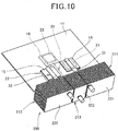
- FIG. 10 is a perspective view showing a conventional heat sink 200.
- the heat sink 200 is constituted of heat receiving plates 14 and 15 thermally connected respectively to a first element 21 and a second element 22 which are disposed on one face of a circuit board 11, a heat receiving plate 16 thermally connected to a third element 23 disposed on the other face of the circuit board 11, heat pipes 31, 32 and 33 whose one ends are attached respectively to these heat receiving plates 14, 15 and 16, and radiation fin parts 211, 212 and 213 attached respective to the other ends of these heat pipes 31, 32 and 33.
- the radiation fin parts 211, 212 and 213 are composed of respective pluralities of rectangular fin plates 221, 222 and 223.
- the heat pipes 31 and 32 can be bent rightward and leftward to widen the distance between the heat pipes 31 and 32 and to make the areas of the fin plates 221, 222 and 223 approximately equivalent to one another.
- Patent Literature 1 Japanese Patent Laid-Open No. 7-190655
- the fin plate 223 disposed on the center side out of the fin plates 221, 222 and 223 is narrow in width and difficult to secure an area required for radiation.
- the fin plates 221 and 222 disposed outside are to have areas excess to the area required for radiation.
- the heat pipe 33 on the center side cannot be sufficiently cooled, and the temperature of the third element 23 connected to the heat pipe 33 sometimes exceeds the allowable maximum temperature.
- differences between the allowable maximum temperature and the temperatures of the elements 21, 22 and 23 become large between the elements 21, 22 and 23.
- the fin plates 221, 222 and 223 sometimes interfere with the pipe bending parts. Since the fin plates 221, 222 and 223 cannot be fixed to the pipe bending parts, the fin plates 221, 222 and 223 cannot be inserted to the vicinity of the circuit board 11. This causes decrease of the number of fin plates and reduction of the areas, which can rather cause deterioration of radiation performance.
- the present invention is devised in view of the aforementioned circumstances, and an object thereof is to optimize, in a heat sink including a plurality of heat pipes, the areas of fin plates provided to the heat pipes.
- a heat sink including: a plurality of heat pipes; and radiation fin parts respectively corresponding to the plurality of heat pipes, the radiation fin parts being fixed to respective end parts of the plurality of heat pipes in a longitudinal direction, each of the plurality of radiation fin parts being composed of a plurality of fin plates, a gap being formed between adjacent fin plates, wherein the fin plate has a fixing part for thermal connection to the heat pipe, and at least one heat pipe is fixed to each fin plate, a fin plate assembly is constituted of the fin plates of the plurality of respective radiation fin parts as the plurality of radiation fin parts are seen from a direction in which the heat pipe extends, the plurality of heat pipes are composed of a first heat pipe group and a second heat pipe group, the first heat pipe group is positioned at a center in a longitudinal direction of the fin plate assembly, and the second heat pipe group is positioned on both sides of the first heat pipe group in the longitudinal direction of the fin plate assembly, and the fin plate thermally
- the area of the fin plate of the radiation fin part can be enlarged by the expanding part, the areas of the fin plates required for the heat pipes by nature can be given, and the areas of the fin plates can be optimized. As a result, cooling performance of the heat sink as an assembly can be improved.
- the heat sink can be downsized as a whole.
- At least one side of the expanding part may be parallel to at least one side of each radiation fin part. According to this configuration, the fin plates can be efficiently disposed in the space.
- At least one side of the expanding part may be oblique to at least one side of each radiation fin part.
- a part of one side in the expanding part may be folded.
- all the plurality of heat pipes are constituted of straight line shapes. According to this configuration, even when the heat pipe are closely disposed to one another into straight line shapes, not only the heat pipe but also the heat sink can be manufactured at low costs while cooling performance of the heat sink is improved.
- a heat sink including: a plurality of heat pipes; and radiation fin parts respectively corresponding to the plurality of heat pipes, the radiation fin parts being fixed to respective end parts of the plurality of heat pipes in a longitudinal direction, each of the plurality of radiation fin parts being composed of a plurality of fin plates, a gap being formed between adjacent fin plates, wherein the fin plate has a fixing part for thermal connection to the heat pipe, and at least one heat pipe is fixed to each fin plate, a fin plate assembly is constituted of the fin plates of the plurality of respective radiation fin parts as the plurality of radiation fin parts are seen from a direction in which the heat pipe extends, the plurality of heat pipes are composed of a first heat pipe group and a second heat pipe group, the first heat pipe group is positioned at a center in a longitudinal direction of the fin plate assembly, and the second heat pipe group is positioned on both sides of the first heat pipe group in the longitudinal direction of the fin plate assembly, and the fin plate thermally connected to the first heat pipe group includes an expanding
- the area of the fin plate of the radiation fin part can be enlarged by the expanding part, the areas of the fin plates required for the heat pipes by nature can be given, and the areas of the fin plates can be optimized. As a result, cooling performance of the heat sink as an assembly can be improved.
- the heat sink can be downsized as a whole. Furthermore, since the fin contact parts of the heat pipes are not needed to be bent to widen the distances, when the one end parts of the heat pipes are attached to the circuit board part, the fin plates can be inserted to the circuit board part. Hence, the number of fin plates is not needed to be reduced, which leads to downsizing.
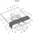
- FIG. 1 is a perspective view showing a heat sink 10 (Embodiment 1) of the present invention.
- the heat sink 10 is constituted of heat receiving plates 14 and 15 thermally connected respectively to a first element 21 and a second element 22 which are disposed on the upper face of a circuit board 11, a heat receiving plate 16 thermally connected to a third element 23 disposed on the lower surface of the circuit board 11, heat pipes 31, 32 and 33 whose one end parts 31a, 32a and 33a sides are attached respectively to these heat receiving plates 14, 15 and 16, and radiation fin parts 34, 35 and 36 attached respectively to the other end parts 31b, 32b and 33b sides of these heat pipes 31, 32 and 33.
- the radiation fin parts 34, 35 and 36 constitute a radiation part 38 whose overall external form is formed into a substantially solid rectangular shape, and the radiation fin parts 34, 35 and 36 are composed of respective pluralities of fin plates 41, 42 and 43.
- the aforementioned heat pipes 31, 32 and 33 extend in parallel or substantially parallel to one another and into straight line shapes, and constitute a heat pipe group 30.
- the heat receiving plates 14, 15 and 16 are components of aluminum alloy plates whose surfaces are nickel-plated, and thermally connected respectively to the elements 21, 22 and 23 via grease.
- the heat pipes 31, 32 and 33 are components of pipes made of highly thermal conductive material such, for example, as copper in which pipes working fluid is sealed, and those one end parts 31a, 32a and 33a which are formed to be flat are soldered respectively to the heat receiving plates 14, 15 and 16.
- the working fluid is vaporized in high temperature parts on the heat receiving plates 14, 15 and 16 sides, the working fluid vapor moves to low temperature parts on the radiation fin parts 34, 35 and 36 sides to be cooled and condensed into liquid, and it returns to the high temperature parts. Such recycling is repeated to conduct heat transfer from the high temperature parts to the low temperature parts.
- the fin plates 41, 42 and 43 are made of aluminum alloy, and are fixed respectively to the heat pipes 31, 32 and 33 at a predetermined pitch by press fitting. Thereby, the fin plates 41, 42 and 43 are perpendicularly or substantially perpendicularly fixed respectively to the heat pipes 31, 32 and 33.
- the radiation fin parts 34, 35 and 36 are disposed spaced from one another at predetermined distances.
- a gap between adjacent fin plates 41, a gap between adjacent fin plates 42, and a gap between adjacent fin plates 43 may be air layers, or heat insulative material may be installed therein. Otherwise, spacers for holding the distances to be constant may be installed therein.
- the gaps for spacing As above, by providing the gaps for spacing, interference of heat can be prevented even when the heat pipes 31, 32 and 33 are close to one another, which enables efficient cooling. Moreover, the gaps with predetermined distances allow air to flow therein to promote cooling.
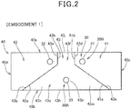
- FIG. 2 is an elevation view showing the fin plates 41, 42 and 43 (Embodiment 1). Notably, predetermined gaps are provided between the fin plates 41, 42 and 43 (between the different fin plates) such that they do not interfere with each other (the same holds true for other fin plates mentioned later).
- FIG. 2 is described, compared with Comparative Example 1 shown in FIG. 11.
- FIG. 11 is an elevation view showing the fin plates 221, 222 and 223 (Comparative Example 1) of the conventional art shown in FIG. 10 .
- the heat pipes 31 and 32 form one line
- the heat pipe 33 is disposed on the straight line that passes the center between the heat pipes 31 and 32 and extends in the direction perpendicular to the direction in which the heat pipes 31 and 32 line up.
- the rectangular fin plate 223 attached to the heat pipe 33 disposed at the center out of the three heat pipes 31, 32 and 33 is narrowest in width and smallest in area of the fin plates 221, 222 and 223. Moreover, although the areas of the fin plates 221 and 222 are larger than the area of the fin plate 223, parts, of the fin plates 221 and 222, close to the heat pipes 31 and 32 largely contribute cooling performance, and the cooling performance gradually decreases as departing from the heat pipes 31 and 32. Accordingly, the fin plates 221 and 222 includes many parts in which the cooling performance is low.
- the fin plates 41, 42 and 43 constitute a fin plate assembly 40 which is rectangular in elevation view, that is, as seen from the direction in which the heat pipes 31, 32 and 33 extend (other fin plate assemblies shown below are described in elevation view as seen from the direction in which the heat pipes extend similarly to the fin plate assembly 40).
- the fin plate assembly 40 includes two long sides 40a and 40b and two short sides 40c and 40d. The long sides 40a and 40b are formed along the direction in which the heat pipes 31, 32 and 33 line up (that is, the direction in which the heat pipes 31 and 32 line up).
- the heat pipe group 30 is composed of a first heat pipe group 30A composed of the heat pipe 33 positioned at the center in the longitudinal direction of the fin plate assembly 40, and a second heat pipe group 30B composed of the heat pipes 31 and 32 disposed on both end part sides in the longitudinal direction of the fin plate assembly 40 with respect to the heat pipe 33. While each of the heat pipe groups 30A and 30B is constituted of a plurality of heat pipes, it may be constituted of one heat pipe.
- the fin plate 43 is formed into an external form obtained by integrally combining a trapezoidal part 43c having oblique sides 43a and 43b on both sides of the heat pipe 33, and a rectangular part 43f which is adjacent to this trapezoidal part 43c and has lateral sides 43d and 43e on the inner sides of the heat pipes 31 and 32.
- the heat pipe 33 is fixed to a fixing part 43p positioned at the center of the fin plate 43 in the longitudinal direction of the fin plate assembly 40.
- the trapezoidal part 43c includes a bottom side 43h constituting the outer edge of the fin plate 43.
- the bottom side 43h is included in the long side 40b of the fin plate assembly 40. In this way, the fin plate 43 is formed so as to expand from the heat pipe 33 side to the bottom side 43h which is the outer edge.
- the rectangular part 43f includes an upper side 43j constituting the outer edge of the fin plate 43.
- the upper side 43j is included in the long side 40a of the fin plate assembly 40.
- the trapezoidal part 43c has expanding parts 43m and 43n which expand in the direction in which the heat pipes 31 and 32 line up (direction in which the long sides 40a and 40b extend) more than the rectangular part 43f.
- the aforementioned expanding parts 43m and 43n are portions that have shapes in which the end part (specifically, the long side 40b side) of the radiation fin part 36 (see FIG. 1 ) is wider than the fixing part 43p to which the heat pipe 33 is fixed in the fin plate 43.
- the fin plates 41 and 42 include oblique sides 41a and 42a provided so as to oppose the oblique sides 43a and 43b of the fin plate 43, and lateral sides 41b and 42b provided so as to oppose the lateral sides 43d and 43e of the fin plate 43.
- the oblique sides 41a and 42a of the fin plates 41 and 42 and the oblique sides 43a and 43b of the fin plate 43 mentioned above may substantially go along the diagonal lines of the fin plate assembly 40.
- FIGS. 3A and 3B are perspective views for explaining the fin plate 43 (Embodiment 1) and a fin plate 44 (Modification).
- FIG. 3A is a perspective view showing the fin plate 43
- FIG. 3B is a perspective view showing the fin plate 44 which is a modification of the fin plate 43.
- the fin plate 44 the same configuration as that of the fin plate 43 is given the same sign and its detailed description is omitted.
- the fin plate 43 shown in FIG. 3A has the oblique sides 43a and 43b in the lower trapezoidal part 43c.
- folded parts 44g and 44h are formed in the fin plate 44 shown in FIG. 3B .
- the fin plate 44 is formed into an external form obtained by integrally combining a trapezoidal part 44c, as its lower part, having oblique sides 44a and 44b on both sides of the heat pipe 33 (see FIG. 1 ), and the rectangular part 43f, as its upper part, having the lateral sides 43d and 43e on the inner sides of the heat pipes 31 and 32(see FIG.
- the trapezoidal part 44c has expanding parts 44m and 44n which expand in the direction in which the heat pipes 31 and 32(see FIG. 2B ) line up more than the rectangular part 43f.
- FIGS. 3A and 3B a fitting hole 43g into which the heat pipe 33 is press-fitted is bored in the trapezoidal parts 43c and 44c.
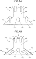
- FIGS. 4A and 4B are operation diagrams for comparing operations in the presence and the absence of the folded parts 44g and 44h of the fin plate 44.
- FIG. 4A is an operation diagram showing operation of the fin plate 43
- FIG. 4B is an operation diagram showing operation of the fin plate 44.
- the fin plate 43 when air flows along the fin plate 43, for example, from the bottom to the top of the fin plate 43, the air passes on the sides of the trapezoidal part 43c and the rectangular part 43f of the fin plate 43 as indicated by void arrows A and A and void arrows B and B to promote radiation from the fin plate 43.
- the rigidity of the fin plate 44 can be enhanced by providing the folded part 44g and 44h, and with the same plate thickness, the fin plate area can be increased, which can improve cooling performance. Furthermore, with the same area, the plate thickness can be made thin, which can realize light weight.
- FIG. 5 is a perspective view showing a heat sink 50 (Embodiment 2) of the present invention.
- the same configuration as that of Embodiment 1 shown in FIG. 1 is given the same sign and its detailed description is omitted.
- the heat sink 50 is different only in radiation fin parts 54, 55 and 56 with respect to the radiation fin parts 34, 35 and 36 (see FIG. 1 ) of the heat sink 10 (see FIG. 1 ).
- the heat sink 50 is constituted of the heat receiving plates 14, 15 and 16, the heat pipes 31, 32 and 33, and the radiation fin parts 54, 55 and 56.
- the three radiation fin parts 54, 55 and 56 constitute a radiation part 58 whose overall external form is formed into a substantially solid rectangular shape, and the radiation fin parts 54, 55 and 56 are composed of respective pluralities of fin plates 61, 62 and 63.
- the fin plate 63 attached to the heat pipe 33 disposed at the center out of the three heat pipes 31, 32 and 33 is formed into a triangular shape.
- FIG. 6 is an elevation view showing the fin plates 61, 62 and 63 (Embodiment 2).
- the fin plates 61, 62 and 63 shown in FIG. 6 have different shapes with their areas being the same. Namely, the fin plate 221, the fin plate 222 and the fin plate 223 have the same areas as those of the fin plate 61, the fin plate 62 and the fin plate 63, respectively. Moreover, the fin plate 221 and the fin plate 61 have the same areas as those of the fin plate 222 and the fin plate 62, respectively.
- the fin plates 61, 62 and 63 constitute a rectangular fin plate assembly 60.
- the fin plate assembly 60 includes two long sides 60a and 60b and two short sides 60c and 60d.
- the long sides 60a and 60b are formed along the direction in which the heat pipes 31, 32 and 33 line up (that is, the direction in which the heat pipes 31 and 32 line up).
- the fin plate 63 is formed into an isosceles triangle having a vertex above the heat pipe 33, and includes two oblique sides 63a and 63b and a bottom side 63c.
- the bottom side 63c is included in the long side 60b of the fin plate assembly 60. In this way, the fin plate 63 is formed so as to expand from the heat pipe 33 side to the bottom side 63c which is the outer edge.
- the fin plate 63 has expanding parts 63d and 63e which expand in the direction in which the heat pipes 31 and 32 line up (direction in which the long sides 60a and 60b extend) more than the heat pipes 31 and 32.
- the heat pipe 33 is fixed to a fixing part 63g positioned at the center of the fin plate 63 in the longitudinal direction of the fin plate assembly 60.
- the aforementioned expanding parts 63d and 63e are portions which have shapes in which the end part (specifically, the long side 60b side) of the radiation fin part 56 (see FIG. 1 ) is wider than the fixing part 63g to which the heat pipe 33 is fixed in the fin plate 63.
- the fin plates 61 and 62 include oblique sides 61a and 62a opposing the oblique sides 63a and 63b of the fin plate 63, and lateral sides 61b and 62b opposing each other.
- the oblique sides 61a and 62a of the fin plates 61 and 62 and the oblique sides 63a and 63b of the fin plate 63 mentioned above may substantially go along the diagonal lines of the fin plate assembly 60.
- Embodiment 1 For Embodiment 1, Embodiment 2 and Comparative Example 1 shown above, relation between the areas and shapes of the fin plates and the temperatures of the elements was evaluated under the following experimental conditions. The evaluation results are presented in Table 1.
- Comparative Example 1 since the temperature of the third element 23 is 53.7 °C and exceeds the allowable maximum temperature, 50 °C, the determination is ⁇ (disqualified). Accordingly, for example, the output of the elements is needed to be reduced, or the wind speed of the cooling wind is needed to be increased using a high power cooling fan.
- the area of the fin plate 43 can be made twice as large as the area of the fin plate 223 (see FIG. 11 ) by forming the oblique sides 43a and 43b in the fin plate 43, which is formed so as to expand from the heat pipe 33 side to the bottom side 43h which is the outer edge.
- the temperature of the third element 23 is 47.4 °C and can be reduced by 6.3 °C as compared with that in Comparative Example 1.
- the determination is ⁇ (qualified).
- portions in which cooling performance is low are eliminated.
- the temperatures of the first element 21 and the second element 22 are increased, the temperature differences between the elements 21, 22 and 23 become small, and the areas can be optimized.
- Embodiment 2 also see FIG. 5 and FIG. 6 ), the areas of the fin plates 61, 62 and 63 are the same as those in Comparative Example 1. Nevertheless, as compared with the Comparative Example 1, the temperatures of the elements 21, 22 and 23 are changed by -2.0 °C for the first element 21, by -1.4 °C for the second element 22, and by -4.6 °C for the third element 23, and the temperatures of all the elements 21, 22 and 23 can be reduced. Accordingly, determination is ⁇ (qualified).
- FIGS. 7A to 7C are elevation views showing fin plate shapes (Embodiment 3, Embodiment 4 and Embodiment 5) corresponding to three heat pipes 71, 72 and 73 that are arranged in one line.
- FIG. 7A is a view showing Embodiment 3 in which each of fin plates 81, 82 and 83 is constituted of a plurality of rectangles.
- FIG. 7B is an elevation view showing Embodiment 4 in which fin plates 85, 86 and 87 are formed so as to expand from the inside to the outside.
- FIG. 7C is an elevation view showing Embodiment 5 in which a fin plate 97 on one side is formed so as to enclose fin plates 95 and 96 on the other side.
- FIGS. 7A to 7C are described, compared with Comparative Example 2 shown in FIG. 12.
- FIG. 12 is an elevation view showing Comparative Example 2 which is a conventional art in which each of fin plates 231, 232 and 233 is formed into a rectangle.
- the heat pipes 71, 72 and 73 are closely disposed to one another and constitute a heat pipe group 70. Divisions between the heat pipes 71 and 73 and between the heat pipes 72 and 73 form the rectangular fin plates 231, 232 and 233. The width of the fin plate 233 out of the three fin plates 231, 232 and 233 is smallest and the area thereof is smallest.
- the fin plates 81, 82 and 83 constitute a rectangular fin plate assembly 80, and the fin plate assembly 80 has long sides 80a and 80b and short sides 80c and 80d.
- the heat pipe group 70 is composed of a first heat pipe group 70A composed of the heat pipe 73 positioned at the center of the fin plate assembly 80 in the longitudinal direction, and a second heat pipe group 70B composed of the heat pipes 71 and 72 disposed on both end part sides of the fin plate assembly 80 in the longitudinal direction with respect to the heat pipe 73. While each of the heat pipe groups 70A and 70B is constituted of a plurality of heat pipes, it may be constituted of one heat pipe.
- the fin plate 81 is composed of an inner rectangular part 81a extending from the heat pipe 71 in the direction in which the heat pipes 71, 72 and 73 line up, and an outer rectangular part 81b which is wider than this inner rectangular part 81a and extends outward integrally from the inner rectangular part 81a.
- the fin plate 82 is composed of an inner rectangular part 82a extending from the heat pipe 72 in the direction in which the heat pipes 71, 72 and 73 line up, and an outer rectangular part 82b which is wider than this inner rectangular part 82a and extends outward integrally from the inner rectangular part 82a.
- the fin plate 83 is composed of an inner rectangular part 83a extending from the heat pipe 73 in the direction perpendicular to the direction in which the heat pipes 71, 72 and 73 line up (upward and downward in the figure), and outer rectangular parts 83b and 83c which are wider than this inner rectangular part 83a and extend outward integrally from the inner rectangular part 83a.
- the outer rectangular parts 83b and 83c include an upper side 83d and a lower side 83e, respectively, included in the long sides 80a and 80b. In this way the fin plate 83 is formed so as to expand from the heat pipe 73 side to the upper side 83d or the lower side 83e which are the outer edges.
- the fin plate 83 has expanding parts 83f, 83g, 83h and 83j which expand in the direction in which the heat pipes 71, 72 and 73 line up (direction in which the long sides 80a and 80b extend) more than the inner rectangular part 83a.
- the fin plate assembly 80 is formed into a rectangle having the long sides 80a and 80b along the direction in which the heat pipes 71, 72 and 73 line up.
- the heat pipe 73 is fixed to the inner rectangular part 83a which is a fixing part positioned at the center of the fin plate assembly 80 in the longitudinal direction in the fin plate 83.
- the aforementioned expanding parts 83f, 83g, 83h and 83j are portions that have shapes in which the end parts (specifically, the long sides 80a and 80b sides) of the fin plate assembly 80 are wider than the inner rectangular part 83a to which the heat pipe 73 is fixed in the fin plate 83.
- the fin plates 85, 86 and 87 constitute a rectangular fin plate assembly 80A, and the fin plate assembly 80A includes long sides 80e and 80f and short sides 80g and 80h.
- the fin plate 85 is formed into a substantial fan shape which extends from the heat pipe 71 in the direction in which the heat pipes 71, 72 and 73 line up, and includes a lateral side 85a formed between the heat pipes 71 and 73, and oblique sides 85b and 85c extending from both end parts of this lateral side 85a obliquely to the direction in which the heat pipes 71, 72 and 73 line up.
- the fin plate 86 is formed into a substantial fan shape which extends from the heat pipe 72 in the direction in which the heat pipes 71, 72 and 73 line up, and includes a lateral side 86a formed between the heat pipes 72 and 73, and oblique sides 86b and 86c extending from both end parts of this lateral side 86a obliquely to the direction in which the heat pipes 71, 72 and 73 line up.
- the fin plate 87 includes lateral sides 87a and 87b which are formed so as to expand from the heat pipe 73 in the direction perpendicular to the direction in which the heat pipes 71, 72 and 73 line up (upward and downward in the figure) and oppose the respective lateral sides 85a and 86a of the fin plates 85 and 86, oblique sides 87c, 87d, 87e and 87f which extend from both end parts of these lateral sides 87a and 87b, opposing the oblique sides 85b, 85c, 86b and 86c of the fin plates 85 and 86, and an upper side 87g and a lower side 87h which are included in the long sides 80e and 80f.
- the fin plate 87 is formed so as to expand from the heat pipe 73 side to the upper side 87g and the lower side 87h which are the outer edges.
- the fin plate 87 has expanding parts 87m, 87n, 87p and 87q which expand in the direction in which the heat pipes 71, 72 and 73 line up (direction in which the long sides 80e and 80f extend) more than between the lateral sides 87a and 87b.
- the fin plate assembly 80A is formed into a rectangle which has the long sides 80e and 80f along the direction in which the heat pipes 71, 72 and 73 line up.
- the oblique sides 85b and 85c of the fin plate 85, the oblique sides 86b and 86c of the fin plate 86, and the oblique sides 87c, 87d, 87e and 87f of the fin plate 87 may go along the diagonal lines of the rectangular fin plate assembly 80A.
- the heat pipe 73 is fixed to a fixing part 87r positioned at the center of the fin plate assembly 80A in the longitudinal direction in the fin plate 87 and between the lateral sides 87a and 87b.
- the aforementioned expanding parts 87m, 87n, 87p and 87q are portions that have shapes in which the end parts (specifically, the long sides 80e and 80f sides) of the fin plate assembly 80A are wider than the fixing part 87r (specifically, the width between the lateral sides 87a and 87b) to which the heat pipe 73 is fixed in the fin plate 87.
- the fin plates 95, 96 and 97 constitute a rectangular fin plate assembly 80B, and the fin plate assembly 80B includes long sides 97h and 97j and short sides 97m and 97n which are the same as in the fin plate 97.
- the fin plate 95 is formed into a rectangle which extends from the heat pipe 71 in the direction in which the heat pipes 71, 72 and 73 line up, and includes a lateral side 95a formed between the heat pipes 71 and 73.
- the fin plate 96 is formed into a rectangle which extends from the heat pipe 72 in the direction in which the heat pipes 71, 72 and 73 line up, and includes a lateral side 96a formed between the heat pipes 72 and 73.
- the fin plate 97 is obtained by integrally forming an inner rectangular part 97a disposed between the fin plates 95 and 96 so as to enclose the heat pipe 73, outer rectangular parts 97b and 97c formed on both sides of this inner rectangular part 97a to be wider than the inner rectangular part 97a, and outer end part rectangular parts 97d and 97e disposed outside the fin plates 95 and 96 and between these outer rectangular parts 97b and 97c.
- the inner rectangular part 97a includes lateral sides 97f and 97g opposing the lateral sides 95a and 96a of the fin plates 95 and 96.
- the outer rectangular part 97b includes the long side 97h
- the outer rectangular part 97c includes the long side 97j.
- the fin plate 97 includes the long sides 97h and 97j and the short sides 97m and 97n, and its external form is rectangular.
- the fin plate 97 is formed so as to expand from the heat pipe 73 side to the long sides 97h and 97j which are the outer edges.
- the outer rectangular parts 97b and 97c have expanding parts 97p, 97q, 97r and 97s which expand in the direction in which the heat pipes 71, 72 and 73 line up (direction in which the long sides 97h and 97j extend) more than the inner rectangular part 97a.
- the heat pipe 73 is fixed to the inner rectangular part 97a as a fixing part positioned at the center in the longitudinal direction in the fin plate 97.
- the aforementioned expanding parts 97p, 97q, 97r and 97s are portions that have shapes in which the end parts (specifically, the long sides 97h and 97j sides) of the fin plate 97 are wider than the inner rectangular part 97a to which the heat pipe 73 is fixed in the fin plate 97.
- the fin plate 83 of Embodiment 3, the fin plate 87 of Embodiment 4, and the fin plate 97 of Embodiment 5 are larger in area than the fin plate 233 of Comparative Example 2, and moreover, can increase the radiation area close to the heat pipe 73 and improve radiation ability.
- FIG. 8 is an elevation view showing fin plate shapes (Embodiment 6) corresponding to four heat pipes 101, 102, 103 and 104 that are arranged in one line.
- FIG. 8 is described, compared with Comparative Example 3 shown in FIG. 13.
- FIG. 13 is an elevation view showing Comparative Example 3 which is a conventional art in which each of fin plates 241, 242, 243 and 244 is formed into a rectangle.
- the heat pipes 101, 102, 103 and 104 are closely disposed to one another and constitute a heat pipe group 100. Divisions between the heat pipes 101 and 103, between the heat pipes 103 and 104 and between the heat pipes 102 and 104 form the rectangular fin plates 241, 242, 243 and 244. The widths of the fin plates 243 and 244 out of the four fin plates 241, 242, 243 and 244 are smallest and the areas thereof are smallest.
- the fin plates 111, 112, 113 and 114 are formed so as to expand from the inside to the outside.
- the fin plates 111, 112, 113 and 114 constitute a rectangular fin plate assembly 110, and the fin plate assembly 110 has long sides 110a and 110b and short sides 110c and 110d.
- the heat pipe group 100 includes a first heat pipe group 100A composed of the heat pipes 103 and 104 positioned at the center in the longitudinal direction of the fin plate assembly 110, and a second heat pipe group 100B composed of the heat pipes 101 and 102 disposed on both end part sides in the longitudinal direction of the fin plate assembly 110 with respect to the heat pipes 103 and 104.
- Each of the heat pipe groups 100A and 70B is constituted of a plurality of heat pipes.
- the fin plate 111 is formed into a substantial fan shape which extends from the heat pipe 101 in the direction in which the heat pipes 101, 102, 103 and 104 line up, and includes a lateral side 111a formed between the heat pipes 101 and 103, and oblique sides 111b and 111c extending from both end parts of this lateral side 111a obliquely to the direction in which the heat pipes 101, 102, 103 and 104 line up.
- the fin plate 112 is formed into a substantial fan shape which extends from the heat pipe 102 in the direction in which the heat pipes 101, 102, 103 and 104 line up, and includes a lateral side 112a formed between the heat pipes 102 and 104, and oblique sides 112b and 112c extending from both end parts of this lateral side 112a obliquely to the direction in which the heat pipes 101, 102, 103 and 104 line up.
- the aforementioned oblique sides 111b, 111c, 112b and 112c of the fin plates 111 and 112 extend along the diagonal lines of the fin plate assembly 110.
- the fin plate 113 is composed of a rectangular part 113g which is formed so as to expand from the heat pipe 103 in the direction perpendicular to the direction in which the heat pipes 101, 102, 103 and 104 line up (upward and downward in the figure) and encloses the heat pipe 103, and trapezoidal parts 113h and 113j integrally formed outside this rectangular part 113g.
- the fin plate 113 includes a lateral side 113a opposing the lateral side 111a of the fin plate 111, oblique sides 113b and 113c extending from both end parts of this lateral side 113a, opposing the oblique sides 111b and 111c of the fin plate 111, a lateral side 113d formed between the heat pipes 103 and 104, an upper side 113e included in the long side 110a, and a lower side 113f included in the long side 110b.
- the fin plate 113 has expanding parts 113m and 113n which expand in the direction in which the heat pipes 101, 102, 103 and 104 line up (direction in which the long sides 110a and 110b extend) more than between the lateral sides 113a and 113d.
- the fin plate 114 includes a rectangular part 114g which is formed so as to expand from the heat pipe 104 in the direction perpendicular to the direction in which the heat pipes 101, 102, 103 and 104 line up (upward and downward in the figure) and encloses the heat pipe 104, and trapezoidal parts 114h and 114j integrally formed outside this rectangular part 114g.
- the fin plate 114 includes a lateral side 114a opposing the lateral side 112a of the fin plate 112, oblique sides 114b and 114c extending from both end parts of this lateral side 114a, opposing the oblique sides 112b and 112c of the fin plate 112, a lateral side 114d which is formed between the heat pipes 103 and 104 and opposes the lateral side 113d of the fin plate 113, an upper side 114e included in the long side 110a, and a lower side 114f included in the long side 110b.
- the fin plate 114 has expanding parts 114m and 114n which expand in the direction in which the heat pipes 101, 102, 103 and 104 line up (direction in which the long sides 110a and 110b extend) more than between the lateral sides 114a and 114d.
- the aforementioned oblique sides 113b, 113c, 114b and 114c of the fin plates 113 and 114 extend along the diagonal lines of the fin plate assembly 110.
- the heat pipes 103 and 104 are fixed to the rectangular parts 113g and 114g as fixing parts positioned at the center in the longitudinal direction of the fin plate assembly 80 in the fin plates 113 and 114.
- the aforementioned expanding parts 113m, 113n, 114m and 114n are portions that have shapes in which the end parts (specifically, the long sides 110a and 110b sides) of the fin plate assembly 110 are wider that the rectangular parts 113g and 114g to which the heat pipes 103 and 104 are fixed in the fin plates 113 and 114.
- the fin plates 113 and 114 are formed so as to expand from the heat pipes 103 and 104 sides to the upper sides 113e and 114e and the lower sides 113f and 114f which are the outer edges.
- the fin plates 113 and 114 of Embodiment 6 are larger in area than the fin plates 243 and 244 of Comparative Example 3, moreover, can increase the radiation areas close to the heat pipes 103 and 104, and thereby, can improve radiation ability.
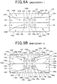
- FIGS. 9A and 9B are elevation views showing fin plate shapes (Embodiment 7 and Embodiment 8) corresponding to six heat pipes 121, 122, 123, 124, 125 and 126 that are arranged in two lines.
- FIG. 9A is an elevation view showing Embodiment 7 in which each of fin plates 131, 132, 133, 134, 135 and 136 is constituted of a single rectangle or a plurality of rectangles.
- FIG. 9B is an elevation view showing Embodiment 8 in which fin plates 141, 142, 143, 144, 145 and 146 are formed so as to expand from the inside to the outside.
- FIGS. 9A and 9B are described, compared with Comparative Example 4 shown in FIG. 14.
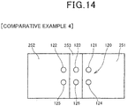
- FIG. 14 is an elevation view showing Comparative Example 4 which is a conventional art in which each of fin plates 251, 252 and 253 is formed into a rectangle.
- the heat pipes 121, 122, 123, 124, 125 and 126 are closely arranged to one another and constitute a heat pipe group 120.
- the fin plate 251 is attached to two heat pipes 121 and 124
- the fin plate 252 is attached to two heat pipes 122 and 125
- the fin plate 253 is attached to two heat pipes 123 and 126. Divisions between the heat pipes 121 and 124 and the heat pipes 123 and 126 and between the heat pipes 123 and 126 and the heat pipes 122 and 125 form the rectangular fin plates 251, 252 and 253.
- the width of the fin plate 253 out of the three fin plates 251, 252 and 253 is smallest and the area thereof is smallest.
- the fin plates 131, 132, 133, 134, 135 and 136 constitute a rectangular fin plate assembly 130, and the fin plate assembly 130 includes long sides 130a and 130b and short sides 130c and 130d.
- the heat pipe group 120 is composed of a first heat pipe group 120A composed of the heat pipes 123 and 126 positioned at the center in the longitudinal direction of the fin plate assembly 130, and a second heat pipe group 120B composed of the heat pipes 121, 122, 124 and 125 disposed on both end sides in the longitudinal direction of the fin plate assembly 130 with respect to the heat pipes 123 and 126.
- Each of the heat pipe groups 120A and 120B is constituted of a plurality of heat pipes.
- the fin plates 131 and 132 are formed into rectangles so as to extend from the heat pipes 121 and 122 in the direction in which the heat pipes 121, 122 and 123 line up.
- the fin plate 133 is composed of an inner rectangular part 133a interposed between the fin plates 131 and 132, and an outer rectangular part 133b which is wider than this inner rectangular part 133a and extends outward integrally from the inner rectangular part 133a.
- the fin plate 133 has expanding parts 133c and 133d which expand in the direction in which the heat pipes 121, 122 and 123 line up (direction in which the long sides 130a and 130b extend) more than the inner rectangular part 133a.
- the fin plates 134 and 135 are formed into rectangles so as to extend from the heat pipes 124 and 125 in the direction in which the heat pipes 124, 125 and 126 line up.
- the fin plate 136 is composed of an inner rectangular part 136a interposed between the fin plates 134 and 135, and an outer rectangular part 136b which is wider than this inner rectangular part 136a and extends outward integrally from the inner rectangular part 136a.
- the fin plate 136 has expanding parts 136c and 136d which expand in the direction in which the heat pipes 124, 125 and 126 line up (direction in which the long sides 130a and 130b extend) more than the inner rectangular part 136a.
- the fin plate 133 includes the long side 130a
- the fin plate 136 includes the long side 130b.
- edge parts of the fin plates 131, 133, 134 and 136 form the short side 130c
- edge parts of the fin plates 132, 133, 135 and 136 form the short side 130d.
- the heat pipes 123 and 126 are fixed to the inner rectangular parts 133a and 136a as fixing parts positioned at the center in the longitudinal direction of the fin plate assembly 130 in the fin plates 133 and 136.
- the aforementioned expanding parts 133c, 133d, 136c and 136d are portions that have shapes in which the end parts (specifically, the long sides 130a and 130b sides) of the fin plate assembly 130 are wider than the inner rectangular parts 133a and 136a to which the heat pipes 123 and 126 are fixed in the fin plates 133 and 136.
- the fin plates 133 and 136 are formed so as to expand from the heat pipes 123 and 126 sides to the long sides 130a and 130b which are the outer edges.
- the fin plates 141, 142, 143, 144, 145 and 146 constitute a rectangular fin plate assembly 140, and the fin plate assembly 140 includes long sides 140a and 140b and short sides 140c and 140d.
- the fin plate 141 is formed into a substantial fan shape which extends from the heat pipe 121 in the direction in which the heat pipes 121, 122 and 123 line up, and includes a lateral side 141a formed between the heat pipes 121 and 123, a lower side 141b extending from one end part of this lateral side 141a in the direction in which the heat pipes 121, 122 and 123 line up, and an oblique side 141c extending from the other end part of the lateral side 141a obliquely to the direction in which the heat pipes 121, 122 and 123 line up.
- the fin plate 142 is formed into a substantial fan shape which extends from the heat pipe 122 in the direction in which the heat pipes 121, 122 and 123 line up, and includes a lateral side 142a formed between the heat pipes 122 and 123, a lower side 142b extending from one end part of this lateral side 142a in the direction in which the heat pipes 121, 122 and 123 line up, and an oblique side 142c extending from the other end part of the lateral side 142a obliquely to the direction in which the heat pipes 121, 122 and 123 line up.
- the fin plate 143 is composed of a rectangular part 143a disposed between the fin plates 141 and 142, and a trapezoidal part 143b formed so as to expand integrally from this rectangular part 143a in the direction perpendicular to the direction in which the heat pipes 121, 122 and 123 line up.
- the rectangular part 143a includes lateral sides 143c and 143d opposing the lateral sides 141a and 142a of the fin plates 141 and 142.
- the trapezoidal part 143b includes oblique sides 143e and 143f opposing the oblique sides 141c and 142c of the fin plates 141 and 142, and the long side 140a is its bottom side.
- the fin plate 143 has expanding parts 143g and 143h which expand in the direction in which the heat pipes 121, 122 and 123 line up (direction in which the long sides 140a and 140b extend) more than the rectangular part 143a.
- the fin plate 144 is formed into a substantial fan shape which extends from the heat pipe 124 in the direction in which the heat pipes 124, 125 and 126 line up, and includes a lateral side 144a formed between the heat pipes 124 and 126, an upper side 144b extending from one end part of this lateral side 144a in the direction in which the heat pipes 124, 125 and 126 line up, and an oblique side 144c extending from the other end part of the lateral side 144a obliquely to the direction in which the heat pipes 124, 125 and 126 line up.
- the fin plate 145 is formed into a substantial fan shape which extends from the heat pipe 125 in the direction in which the heat pipes 124, 125 and 126 line up, and includes a lateral side 145a formed between the heat pipes 125 and 126, an upper side 145b extending from one end part of this lateral side 145a in the direction in which the heat pipes 124, 125 and 126 line up, and an oblique side 145c extending from the other end part of the lateral side 145a obliquely to the direction in which the heat pipes 124, 125 and 126 line up.
- the fin plate 146 is composed of a rectangular part 146a disposed between the fin plates 144 and 145, and a trapezoidal part 146b formed so as to expand integrally from this rectangular part 146a in the direction perpendicular to the direction in which the heat pipes 124, 125 and 126 line up.
- the rectangular part 146a includes lateral sides 146c and 146d opposing the lateral sides 144a and 145a of the fin plates 144 and 145.
- the trapezoidal part 146b includes oblique sides 146e and 146f opposing the oblique sides 144c and 145c of the fin plates 144 and 145, and the long side 140b is its bottom side.
- the fin plate 146 has expanding parts 146g and 146h which expand in the direction in which the heat pipes 124, 125 and 126 (direction in which the long sides 140a and 140b extend) more than the rectangular part 146a.
- the oblique side 141c of the fin plate 141, the oblique side 142c of the fin plate 142, the oblique sides 143e and 143f of the fin plate 143, the oblique side 144c of the fin plate 144, the oblique side 145c of the fin plate 145, and the oblique sides 146e and 146f of the fin plate 146 mentioned above may go along the diagonal lines of the rectangle formed of the outer edges of the fin plate assembly 140.
- the heat pipes 123 and 126 are fixed to the rectangular parts 143a and 146a as fixing parts positioned at the center in the longitudinal direction of the fin plate assembly 140 in the fin plates 143 and 146.
- the aforementioned expanding parts 143g, 143h, 146g and 146h are portions that have shapes in which the end parts (specifically, the long sides 140a and 140b sides) of the fin plate assembly 140 are wider than the rectangular parts 143a and 146a to which the heat pipes 123 and 126 are fixed in the fin plates 143 and 146.
- the fin plates 143 and 146 are formed so as to expand from the heat pipes 123 and 126 sides to the long sides 140a and 140b which are the outer edges.
- the fin plates 133 and 136 of Embodiment 7, and the fin plates 143 and 146 of Embodiment 8 are larger in area than the upper or lower half of the fin plate 253 of Comparative Example 4, moreover, can increase the radiation areas close to the heat pipes 123 and 126, and thereby, can improve radiation ability.
- a heat sink is composed of a plurality of heat pipes 31, 32 and 33 and radiation fin parts 34, 35 and 36 corresponding to the plurality of respective heat pipes 31, 32 and 33, the radiation fin parts 34, 35 and 36 being fixed to respective end parts of the plurality of heat pipes 31, 32 and 33 in the longitudinal direction, each of the plurality of radiation fin parts 34, 35 and 36 being composed of a plurality of fin plates 41, 42, 43, gaps being formed between adjacent fin plates 41, between adjacent fin plates 42 and between adjacent fin plates 43, wherein the fin plate 41, 42, 43 has a fixing part 43p for thermal connection to the heat pipe 31, 32, 33, and at least one heat pipe 31, 32, 33 is fixed to each fin plate 41, 42, 43, a rectangular fin plate assembly 40 is constituted of the fin plate 41, the fin plate 42 and the fin plate 43 of the plurality of respective radiation fin parts 34, 35 and 36 as the plurality of radiation fin parts 34, 35 and 36 are seen from the direction in which the heat pipe 31, 32, 33 extends
- the heat sink 10 constituted of: the heat receiving plates 14, 15 and 16 to which the first element 21, the second element 22 and the third element 23 as heat generating bodies are thermally connected; the heat pipe group 30 composed of the plurality of heat pipes 31, 32 and 33 whose one end parts 31a, 32a and 33a are connected to these heat receiving plates 14, 15 and 16, to the other end parts 31b, 32b and 33b of which heat is transferred from the one end parts 31a, 32a and 33a, and which are closely disposed to one another; and the radiation fin parts 34, 35 and 36 composed of the fin plates 41, 42 and 43 thermally connected respectively to the other end parts 31b, 32b and 33b of the plurality of heat pipes 31, 32 and 33, the fin plates 41, 42 and 43 are attached to each of the heat pipes 31, 32 and 33, and the fin plate 43 attached to the heat pipe 33 as an inner heat pipe disposed on the center side of the heat pipe group 30 out of the heat pipes 31, 32 and 33 is formed so as to expand from the
- the area of the fin plate 43 connected to the heat pipe 33 can be increased, the areas of the fin plates 41, 42 and 43 required for the respective heat pipes 31, 32 and 33 by nature can be given, and the areas of the fin plates 41, 42 and 43 can be optimized.
- cooling performance of the heat sink 10 as an assembly of those can be improved.
- excess fin areas of the fin plates 41 and 42 connected to the outer heat pipes 31 and 32 can be reduced, and hence, the heat sink 10 can be made small as a whole.
- the heat pipes 31, 32 and 33 can be manufactured at low costs while cooling performance of the heat sink 10 is improved.
- the overall external form of the fin plates 41, 42 and 43 attached to the plurality of heat pipes 31, 32 and 33 is rectangular, and hence, the fin plates 41, 42 and 43 can be efficiently disposed in the space.
- the rectangle has the long sides 40a and 40b or the short sides 40c and 40d such that they go along the direction in which the plurality of heat pipes 31, 32 and 33 are arranged, and hence, the heat pipes 31, 32 and 33 can be disposed substantially at the centers of the respective fin plates 41, 42 and 43, which can realize more uniform radiation to the peripheries of the heat pipes 31, 32 and 33.
- the radiation fin parts 34, 35 and 36 can be easily closely disposed to one another and the heat sink 10 can be easily assembled.
- the oblique sides 44a and 44b as the edge parts extending substantially along the diagonal lines of the rectangle are substantially perpendicularly folded, air flowing along the fin plate 44 can be collected by the folded parts 44g and 44h which are folded, and the air can be effectively blown onto the fin plate 44, which can lead to increase of the air flow rate and efficient cooling of the fin plate 44.
- folding the edge parts can improve the rigidity of the fin plate 44 and make it hardly deformed.
- the plate thickness of the fin plate 44 can be formed to be thinner, which can make the fin plate 44 lightweight.
- the fin plate 83 is formed into a shape obtained by combining the inner rectangular part 83a and the outer rectangular parts 83b and 83c as a plurality of rectangles, costs can be reduced by a simple shape with the area of the fin plate 83 increased.
- the overall external form of the fin plate assembly may be an incomplete rectangle, and its corner parts may be formed into arc shapes or beveled shapes. Moreover, a part of the fin plate assembly may be cut out.
- the expanding part may be provided in the fin plate of the heat sink at the end part to secure the required area.
Landscapes
- Engineering & Computer Science (AREA)
- Physics & Mathematics (AREA)
- Thermal Sciences (AREA)
- Mechanical Engineering (AREA)
- General Engineering & Computer Science (AREA)
- Life Sciences & Earth Sciences (AREA)
- Sustainable Development (AREA)
- Geometry (AREA)
- Cooling Or The Like Of Electrical Apparatus (AREA)
- Cooling Or The Like Of Semiconductors Or Solid State Devices (AREA)
Abstract
Description
- The present invention relates to a heat sink in which radiation fin parts are provided to a plurality of heat pipes closely disposed to one another.
- There is known one among heat sinks that adjusts cooling performance by changing the number of fin plates attached to each heat pipe (for example, see Patent Literature 1). Nevertheless, change of the number of fin plates requires an installation space for the number of fin plates. Although it can be otherwise considered that the distance between the fin plates is made narrow to increase the number of fin plates, since the narrow distance between the fin plates makes air difficult to flow therethrough, cooling efficiency is not much improved, or cooling efficiency deteriorates.
- As to heat pipes shown in
Patent Literature 1, when adjacent heat pipes are closely disposed to each other, for example, due to restriction in shape, in order to adjust cooling performance for each heat pipe, there is a method in which fin plates are divided into rectangles between the heat pipes as shown inFIG. 10 . -
FIG. 10 is a perspective view showing aconventional heat sink 200. - In
FIG. 10 , theheat sink 200 is constituted ofheat receiving plates first element 21 and asecond element 22 which are disposed on one face of acircuit board 11, aheat receiving plate 16 thermally connected to athird element 23 disposed on the other face of thecircuit board 11,heat pipes heat receiving plates fin parts heat pipes - The radiation
fin parts rectangular fin plates - Moreover, in
FIG. 10 , theheat pipes heat pipes fin plates - Patent Literature 1: Japanese Patent Laid-Open No.
7-190655 - As mentioned above, when the
fin plates fin plate 223 disposed on the center side out of thefin plates fin plates heat pipe 33 on the center side cannot be sufficiently cooled, and the temperature of thethird element 23 connected to theheat pipe 33 sometimes exceeds the allowable maximum temperature. Moreover, differences between the allowable maximum temperature and the temperatures of theelements elements - Accordingly, it is desired to reduce the maximum temperature of the
third element 23 and to more reduce the differences between the allowable maximum temperature and the temperatures of theelements elements fin plates - Moreover, when the
heat pipes heat pipes fin plates fin plates fin plates circuit board 11. This causes decrease of the number of fin plates and reduction of the areas, which can rather cause deterioration of radiation performance. - The present invention is devised in view of the aforementioned circumstances, and an object thereof is to optimize, in a heat sink including a plurality of heat pipes, the areas of fin plates provided to the heat pipes.
- In order to solve the aforementioned problem, there is provided a heat sink according to the present invention, including: a plurality of heat pipes; and radiation fin parts respectively corresponding to the plurality of heat pipes, the radiation fin parts being fixed to respective end parts of the plurality of heat pipes in a longitudinal direction, each of the plurality of radiation fin parts being composed of a plurality of fin plates, a gap being formed between adjacent fin plates, wherein the fin plate has a fixing part for thermal connection to the heat pipe, and at least one heat pipe is fixed to each fin plate, a fin plate assembly is constituted of the fin plates of the plurality of respective radiation fin parts as the plurality of radiation fin parts are seen from a direction in which the heat pipe extends, the plurality of heat pipes are composed of a first heat pipe group and a second heat pipe group, the first heat pipe group is positioned at a center in a longitudinal direction of the fin plate assembly, and the second heat pipe group is positioned on both sides of the first heat pipe group in the longitudinal direction of the fin plate assembly, and the fin plate thermally connected to the first heat pipe group includes an expanding part.
- According to this configuration, the area of the fin plate of the radiation fin part can be enlarged by the expanding part, the areas of the fin plates required for the heat pipes by nature can be given, and the areas of the fin plates can be optimized. As a result, cooling performance of the heat sink as an assembly can be improved.
- Furthermore, since excess fin areas of the fin plates connected to the heat pipes can be reduced, the heat sink can be downsized as a whole.
- In the aforementioned configuration, at least one side of the expanding part may be parallel to at least one side of each radiation fin part. According to this configuration, the fin plates can be efficiently disposed in the space.
- Moreover, in the aforementioned configuration, at least one side of the expanding part may be oblique to at least one side of each radiation fin part.
- Moreover, in the aforementioned configuration, a part of one side in the expanding part may be folded.
- Moreover, in the aforementioned configuration, all the plurality of heat pipes are constituted of straight line shapes. According to this configuration, even when the heat pipe are closely disposed to one another into straight line shapes, not only the heat pipe but also the heat sink can be manufactured at low costs while cooling performance of the heat sink is improved.
- There is provided a heat sink according to the present invention, including: a plurality of heat pipes; and radiation fin parts respectively corresponding to the plurality of heat pipes, the radiation fin parts being fixed to respective end parts of the plurality of heat pipes in a longitudinal direction, each of the plurality of radiation fin parts being composed of a plurality of fin plates, a gap being formed between adjacent fin plates, wherein the fin plate has a fixing part for thermal connection to the heat pipe, and at least one heat pipe is fixed to each fin plate, a fin plate assembly is constituted of the fin plates of the plurality of respective radiation fin parts as the plurality of radiation fin parts are seen from a direction in which the heat pipe extends, the plurality of heat pipes are composed of a first heat pipe group and a second heat pipe group, the first heat pipe group is positioned at a center in a longitudinal direction of the fin plate assembly, and the second heat pipe group is positioned on both sides of the first heat pipe group in the longitudinal direction of the fin plate assembly, and the fin plate thermally connected to the first heat pipe group includes an expanding part. Hence, the area of the fin plate of the radiation fin part can be enlarged by the expanding part, the areas of the fin plates required for the heat pipes by nature can be given, and the areas of the fin plates can be optimized. As a result, cooling performance of the heat sink as an assembly can be improved.
- Furthermore, since excess fin plate areas of the fin plates connected to the heat pipes can be reduced, the heat sink can be downsized as a whole. Furthermore, since the fin contact parts of the heat pipes are not needed to be bent to widen the distances, when the one end parts of the heat pipes are attached to the circuit board part, the fin plates can be inserted to the circuit board part. Hence, the number of fin plates is not needed to be reduced, which leads to downsizing.
-
- [
FIG. 1] FIG. 1 is a perspective view showing a heat sink (Embodiment 1) of the present invention. - [
FIG. 2] FIG. 2 is an elevation view showing fin plates (Embodiment 1). - [
FIGS. 3A and 3B] FIGS. 3A and 3B are perspective views for explaining fin plates (Embodiment 1 and Modification).FIG. 3A is a perspective view showing the fin plate.FIG. 3B is a perspective view showing a fin plate that is a modification of that fin plate. - [
FIGS. 4A and 4B] FIGS. 4A and 4B are operation diagrams for comparing operations in the presence and the absence of folded parts of the fin plate (Modification).FIG. 4A is an operation diagram showing operation of the fin plate.FIG. 4B is an operation diagram showing Modification of the fin plate. - [
FIG. 5] FIG. 5 is a perspective view showing a heat sink (Embodiment 2) of the present invention. - [
FIG. 6] FIG. 6 is an elevation view showing fin plates (Embodiment 2). - [
FIGS. 7A to 7C] FIGS. 7A to 7C are elevation views showing fin plate shapes (Embodiment 3,Embodiment 4 and Embodiment 5) corresponding to three heat pipes that are arranged in one line.FIG. 7A is an elevationview showing Embodiment 3 in which each of fin plates is constituted of a plurality of rectangles.FIG. 7B is an elevationview showing Embodiment 4 in which fin plates are formed so as to expand from the inside to the outside.FIG. 7C is an elevation view showing Embodiment 5 in which one fin plate is formed so as to enclose the other fin plates. - [
FIG. 8] FIG. 8 is an elevation view showing fin plate shapes (Embodiment 6) corresponding to four heat pipes that are arranged in one line. - [
FIGS. 9A and 9B] FIGS. 9A and 9B are elevation views showing fin plate shapes (Embodiment 7 and Embodiment 8) corresponding to six heat pipes that are arranged in two lines.FIG. 9A is an elevation view showing Embodiment 7 in which each of fin plates is constituted of a single rectangle or a plurality of rectangles.FIG. 9B is an elevation view showing Embodiment 8 in which each of fin plates is formed so as to expand from the inside to the outside. - [
FIG. 10] FIG. 10 is a perspective view showing a conventional heat sink. - [
FIG. 11] FIG. 11 is an elevation view showing fin plates (Comparative Example 1) of the conventional art shown inFIG. 10 . - [
FIG. 12] FIG. 12 is an elevation view showing Comparative Example 2 which is a conventional art in which each fin plate is formed into a rectangle. - [
FIG. 13] FIG. 13 is an elevation view showing Comparative Example 3 which is a conventional art in which each fin plate is formed into a rectangle. - [
FIG. 14] FIG. 14 is an elevation view showing Comparative Example 4 which is a conventional art in which each fin plate is formed into a rectangle. - Hereafter, embodiments of the present invention are described with reference to the drawings.
-
FIG. 1 is a perspective view showing a heat sink 10 (Embodiment 1) of the present invention. - The
heat sink 10 is constituted ofheat receiving plates first element 21 and asecond element 22 which are disposed on the upper face of acircuit board 11, aheat receiving plate 16 thermally connected to athird element 23 disposed on the lower surface of thecircuit board 11,heat pipes end parts heat receiving plates radiation fin parts other end parts heat pipes radiation fin parts radiation part 38 whose overall external form is formed into a substantially solid rectangular shape, and theradiation fin parts fin plates aforementioned heat pipes heat pipe group 30. - The
heat receiving plates elements - The
heat pipes end parts heat receiving plates - In the
heat pipes heat receiving plates radiation fin parts - The
fin plates heat pipes fin plates heat pipes - The
radiation fin parts adjacent fin plates 41, a gap betweenadjacent fin plates 42, and a gap betweenadjacent fin plates 43 may be air layers, or heat insulative material may be installed therein. Otherwise, spacers for holding the distances to be constant may be installed therein. - As above, by providing the gaps for spacing, interference of heat can be prevented even when the
heat pipes -
FIG. 2 is an elevation view showing thefin plates fin plates FIG. 2 is described, compared with Comparative Example 1 shown inFIG. 11. FIG. 11 is an elevation view showing thefin plates FIG. 10 . - In Comparative Example 1 of
FIG. 11 , theheat pipes heat pipe 33 is disposed on the straight line that passes the center between theheat pipes heat pipes - The
rectangular fin plate 223 attached to theheat pipe 33 disposed at the center out of the threeheat pipes fin plates fin plates fin plate 223, parts, of thefin plates heat pipes heat pipes fin plates - In
Embodiment 1 shown inFIG. 2 , thefin plates fin plate assembly 40 which is rectangular in elevation view, that is, as seen from the direction in which theheat pipes fin plate assembly 40 includes twolong sides short sides long sides heat pipes heat pipes - The
heat pipe group 30 is composed of a firstheat pipe group 30A composed of theheat pipe 33 positioned at the center in the longitudinal direction of thefin plate assembly 40, and a secondheat pipe group 30B composed of theheat pipes fin plate assembly 40 with respect to theheat pipe 33. While each of theheat pipe groups - The
fin plate 43 is formed into an external form obtained by integrally combining atrapezoidal part 43c havingoblique sides heat pipe 33, and arectangular part 43f which is adjacent to thistrapezoidal part 43c and haslateral sides heat pipes - The
heat pipe 33 is fixed to a fixingpart 43p positioned at the center of thefin plate 43 in the longitudinal direction of thefin plate assembly 40. - The
trapezoidal part 43c includes abottom side 43h constituting the outer edge of thefin plate 43. Thebottom side 43h is included in thelong side 40b of thefin plate assembly 40. In this way, thefin plate 43 is formed so as to expand from theheat pipe 33 side to thebottom side 43h which is the outer edge. - The
rectangular part 43f includes anupper side 43j constituting the outer edge of thefin plate 43. Theupper side 43j is included in thelong side 40a of thefin plate assembly 40. - The
trapezoidal part 43c has expandingparts heat pipes long sides rectangular part 43f. - The aforementioned expanding
parts long side 40b side) of the radiation fin part 36 (seeFIG. 1 ) is wider than the fixingpart 43p to which theheat pipe 33 is fixed in thefin plate 43. - The
fin plates oblique sides oblique sides fin plate 43, andlateral sides lateral sides fin plate 43. - The oblique sides 41a and 42a of the
fin plates oblique sides fin plate 43 mentioned above may substantially go along the diagonal lines of thefin plate assembly 40. - Here, comparing
Embodiment 1 inFIG. 2 with Comparative Example 1 inFIG. 11 , in thefin plate 43, the radiation area close to theheat pipe 33 is increased, and thereby, cooling ability of theheat pipe 33 can be improved. -
FIGS. 3A and 3B are perspective views for explaining the fin plate 43 (Embodiment 1) and a fin plate 44 (Modification).FIG. 3A is a perspective view showing thefin plate 43, andFIG. 3B is a perspective view showing thefin plate 44 which is a modification of thefin plate 43. Notably, as to thefin plate 44, the same configuration as that of thefin plate 43 is given the same sign and its detailed description is omitted. - The
fin plate 43 shown inFIG. 3A has theoblique sides trapezoidal part 43c. Hence, using theseoblique sides parts fin plate 44 shown inFIG. 3B . Namely, thefin plate 44 is formed into an external form obtained by integrally combining atrapezoidal part 44c, as its lower part, havingoblique sides FIG. 1 ), and therectangular part 43f, as its upper part, having thelateral sides heat pipes 31 and 32(seeFIG. 1 ), and includes the foldedparts oblique sides trapezoidal part 44c. Moreover, thetrapezoidal part 44c has expandingparts heat pipes 31 and 32(seeFIG. 2B ) line up more than therectangular part 43f. - In
FIGS. 3A and 3B , afitting hole 43g into which theheat pipe 33 is press-fitted is bored in thetrapezoidal parts - Operation of the
fin plate 44 mentioned above is next described. -
FIGS. 4A and 4B are operation diagrams for comparing operations in the presence and the absence of the foldedparts fin plate 44.FIG. 4A is an operation diagram showing operation of thefin plate 43, andFIG. 4B is an operation diagram showing operation of thefin plate 44. - As shown in
FIG. 4A , as to thefin plate 43, when air flows along thefin plate 43, for example, from the bottom to the top of thefin plate 43, the air passes on the sides of thetrapezoidal part 43c and therectangular part 43f of thefin plate 43 as indicated by void arrows A and A and void arrows B and B to promote radiation from thefin plate 43. - On the contrary, as shown in
FIG. 4B , as to thefin plate 44, when air flows along thefin plate 44, for example, from the bottom to the top of thefin plate 44, the air bumps against the foldedparts trapezoidal part 44c, and flows obliquely upward along the foldedparts fin plate 44. As a result, the air flow rate increases on the sides of therectangular part 43f, and an upward flow as indicated by void arrows D and D is realized. - Accordingly, cooling with more air flow than in the case of
FIG. 4A is realized in therectangular part 43f, which can lead to more efficient cooling. Moreover, the rigidity of thefin plate 44 can be enhanced by providing the foldedpart -
FIG. 5 is a perspective view showing a heat sink 50 (Embodiment 2) of the present invention. The same configuration as that ofEmbodiment 1 shown inFIG. 1 is given the same sign and its detailed description is omitted. - The
heat sink 50 is different only inradiation fin parts radiation fin parts FIG. 1 ) of the heat sink 10 (seeFIG. 1 ). Namely, theheat sink 50 is constituted of theheat receiving plates heat pipes radiation fin parts radiation fin parts radiation part 58 whose overall external form is formed into a substantially solid rectangular shape, and theradiation fin parts fin plates - The
fin plate 63 attached to theheat pipe 33 disposed at the center out of the threeheat pipes -
FIG. 6 is an elevation view showing thefin plates - With respect to the
fin plates FIG. 11 , thefin plates FIG. 6 have different shapes with their areas being the same. Namely, thefin plate 221, thefin plate 222 and thefin plate 223 have the same areas as those of thefin plate 61, thefin plate 62 and thefin plate 63, respectively. Moreover, thefin plate 221 and thefin plate 61 have the same areas as those of thefin plate 222 and thefin plate 62, respectively. - In
FIG. 6 , thefin plates fin plate assembly 60. Thefin plate assembly 60 includes twolong sides short sides long sides heat pipes heat pipes - The
fin plate 63 is formed into an isosceles triangle having a vertex above theheat pipe 33, and includes twooblique sides bottom side 63c. Thebottom side 63c is included in thelong side 60b of thefin plate assembly 60. In this way, thefin plate 63 is formed so as to expand from theheat pipe 33 side to thebottom side 63c which is the outer edge. - Moreover, the
fin plate 63 has expandingparts heat pipes long sides heat pipes - The
heat pipe 33 is fixed to a fixingpart 63g positioned at the center of thefin plate 63 in the longitudinal direction of thefin plate assembly 60. - The aforementioned expanding
parts long side 60b side) of the radiation fin part 56 (seeFIG. 1 ) is wider than the fixingpart 63g to which theheat pipe 33 is fixed in thefin plate 63. - The
fin plates oblique sides oblique sides fin plate 63, andlateral sides - The oblique sides 61a and 62a of the
fin plates oblique sides fin plate 63 mentioned above may substantially go along the diagonal lines of thefin plate assembly 60. - Here, comparing
Embodiment 2 inFIG. 6 with Comparative Example 1 inFIG. 11 , in thefin plates heat pipes heat pipes - For
Embodiment 1,Embodiment 2 and Comparative Example 1 shown above, relation between the areas and shapes of the fin plates and the temperatures of the elements was evaluated under the following experimental conditions. The evaluation results are presented in Table 1. -
- (a) The calorific values and sizes of the elements
- First element: 15 W, 20 mm × 15 mm
- Second element: 15 W, 30 mm × 30 mm
- Third element: 25 W, 20 mm × 20 mm
For all of these, dummy elements in each of which a ceramic heater (MS-1, Sakaguchi E. H VOC Corporation) was attached to a copper block with the aforementioned size were used for measurement. - (b) The wind speed of cooling wind flowing from the top to the bottom of each fin plate: 1.5 m/s
- (c) The thermal conductivity of thermal conductive grease between the element and the heat receiving plate: 6 W/mK
- (d) The heat receiving plate: 30 mm × 30 mm of dimensions, 1 mm of plate thickness, and the material was nickel-plated aluminum alloy
- (e) The joint part to the heat receiving plate in the heat pipe: was obtained by forming a copper pipe with 8 mm of diameter to be flat with 4 mm of thickness
- (f) The fin plates: the material was aluminum alloy, 0.3 mm of plate thickness, 2 mm of pitch, the quantity per one heat pipe was 20
- (g) The atmospheric temperature: 20 °C
- (h) The load time: 30 min
- (i) The sites of the temperatures measured: the surface temperatures of the first element, the second element and the third element
- (j) The method of measuring the temperature: a thermocouple (K-6F, Sakaguchi E. H VOC Corporation) was installed in a groove formed on the surface of the dummy element, and the center temperature of the dummy element was measured
- As a result, in Comparative Example 1 (also see
FIG. 10 andFIG. 11 ), since the temperature of thethird element 23 is 53.7 °C and exceeds the allowable maximum temperature, 50 °C, the determination is × (disqualified). Accordingly, for example, the output of the elements is needed to be reduced, or the wind speed of the cooling wind is needed to be increased using a high power cooling fan. - Meanwhile, in Embodiment 1 (also see
FIG. 1 andFIG. 2 ), the area of thefin plate 43 can be made twice as large as the area of the fin plate 223 (seeFIG. 11 ) by forming theoblique sides fin plate 43, which is formed so as to expand from theheat pipe 33 side to thebottom side 43h which is the outer edge. As a result, the temperature of thethird element 23 is 47.4 °C and can be reduced by 6.3 °C as compared with that in Comparative Example 1. Moreover, since it is not more than 50 °C, the determination is ○ (qualified). Moreover, as compared with thefin plates 221 and 222 (seeFIG. 11 ), in thefin plates first element 21 and thesecond element 22 are increased, the temperature differences between theelements - In Embodiment 2 (also see
FIG. 5 andFIG. 6 ), the areas of thefin plates elements first element 21, by -1.4 °C for thesecond element 22, and by -4.6 °C for thethird element 23, and the temperatures of all theelements - Other embodiments of the fin plate shapes mentioned above are shown below.
-
FIGS. 7A to 7C are elevation views showing fin plate shapes (Embodiment 3,Embodiment 4 and Embodiment 5) corresponding to threeheat pipes FIG. 7A is aview showing Embodiment 3 in which each offin plates FIG. 7B is an elevationview showing Embodiment 4 in whichfin plates FIG. 7C is an elevation view showing Embodiment 5 in which afin plate 97 on one side is formed so as to enclosefin plates FIGS. 7A to 7C are described, compared with Comparative Example 2 shown inFIG. 12. FIG. 12 is an elevation view showing Comparative Example 2 which is a conventional art in which each offin plates - As shown in
FIG. 12 , theheat pipes heat pipe group 70. Divisions between theheat pipes heat pipes rectangular fin plates fin plate 233 out of the threefin plates - As shown in
FIG. 7A , thefin plates fin plate assembly 80, and thefin plate assembly 80 haslong sides short sides - The
heat pipe group 70 is composed of a firstheat pipe group 70A composed of theheat pipe 73 positioned at the center of thefin plate assembly 80 in the longitudinal direction, and a secondheat pipe group 70B composed of theheat pipes fin plate assembly 80 in the longitudinal direction with respect to theheat pipe 73. While each of theheat pipe groups - The
fin plate 81 is composed of an innerrectangular part 81a extending from theheat pipe 71 in the direction in which theheat pipes rectangular part 81b which is wider than this innerrectangular part 81a and extends outward integrally from the innerrectangular part 81a. - Likewise, the
fin plate 82 is composed of an innerrectangular part 82a extending from theheat pipe 72 in the direction in which theheat pipes rectangular part 82b which is wider than this innerrectangular part 82a and extends outward integrally from the innerrectangular part 82a. - The
fin plate 83 is composed of an innerrectangular part 83a extending from theheat pipe 73 in the direction perpendicular to the direction in which theheat pipes rectangular parts rectangular part 83a and extend outward integrally from the innerrectangular part 83a. The outerrectangular parts upper side 83d and alower side 83e, respectively, included in thelong sides fin plate 83 is formed so as to expand from theheat pipe 73 side to theupper side 83d or thelower side 83e which are the outer edges. - The
fin plate 83 has expandingparts heat pipes long sides rectangular part 83a. - The
fin plate assembly 80 is formed into a rectangle having thelong sides heat pipes - The
heat pipe 73 is fixed to the innerrectangular part 83a which is a fixing part positioned at the center of thefin plate assembly 80 in the longitudinal direction in thefin plate 83. - The aforementioned expanding
parts long sides fin plate assembly 80 are wider than the innerrectangular part 83a to which theheat pipe 73 is fixed in thefin plate 83. - As shown in
FIG. 7B , thefin plates fin plate assembly 80A, and thefin plate assembly 80A includeslong sides short sides - The
fin plate 85 is formed into a substantial fan shape which extends from theheat pipe 71 in the direction in which theheat pipes lateral side 85a formed between theheat pipes oblique sides lateral side 85a obliquely to the direction in which theheat pipes - Likewise, the
fin plate 86 is formed into a substantial fan shape which extends from theheat pipe 72 in the direction in which theheat pipes lateral side 86a formed between theheat pipes oblique sides lateral side 86a obliquely to the direction in which theheat pipes - The fin plate 87 includes
lateral sides 87a and 87b which are formed so as to expand from theheat pipe 73 in the direction perpendicular to the direction in which theheat pipes lateral sides fin plates oblique sides lateral sides 87a and 87b, opposing theoblique sides fin plates upper side 87g and alower side 87h which are included in thelong sides heat pipe 73 side to theupper side 87g and thelower side 87h which are the outer edges. - Moreover, the fin plate 87 has expanding
parts heat pipes long sides lateral sides 87a and 87b. - The
fin plate assembly 80A is formed into a rectangle which has thelong sides heat pipes fin plate 85, the oblique sides 86b and 86c of thefin plate 86, and theoblique sides fin plate assembly 80A. - The
heat pipe 73 is fixed to a fixingpart 87r positioned at the center of thefin plate assembly 80A in the longitudinal direction in the fin plate 87 and between thelateral sides 87a and 87b. - The aforementioned expanding
parts long sides fin plate assembly 80A are wider than the fixingpart 87r (specifically, the width between thelateral sides 87a and 87b) to which theheat pipe 73 is fixed in the fin plate 87. - As shown in
FIG. 7C , thefin plates fin plate assembly 80B, and thefin plate assembly 80B includeslong sides short sides fin plate 97. - The
fin plate 95 is formed into a rectangle which extends from theheat pipe 71 in the direction in which theheat pipes lateral side 95a formed between theheat pipes fin plate 96 is formed into a rectangle which extends from theheat pipe 72 in the direction in which theheat pipes lateral side 96a formed between theheat pipes - The
fin plate 97 is obtained by integrally forming an innerrectangular part 97a disposed between thefin plates heat pipe 73, outerrectangular parts rectangular part 97a to be wider than the innerrectangular part 97a, and outer end partrectangular parts fin plates rectangular parts - The inner
rectangular part 97a includeslateral sides lateral sides fin plates rectangular part 97b includes thelong side 97h, and the outerrectangular part 97c includes thelong side 97j. The outer end partrectangular parts rectangular parts short sides fin plate 97 includes thelong sides short sides - In this way, the
fin plate 97 is formed so as to expand from theheat pipe 73 side to thelong sides - The outer
rectangular parts parts heat pipes long sides rectangular part 97a. - The
heat pipe 73 is fixed to the innerrectangular part 97a as a fixing part positioned at the center in the longitudinal direction in thefin plate 97. - The aforementioned expanding
parts long sides fin plate 97 are wider than the innerrectangular part 97a to which theheat pipe 73 is fixed in thefin plate 97. - In
FIGS. 7A to 7C andFIG. 12 above, thefin plate 83 ofEmbodiment 3, the fin plate 87 ofEmbodiment 4, and thefin plate 97 of Embodiment 5 are larger in area than thefin plate 233 of Comparative Example 2, and moreover, can increase the radiation area close to theheat pipe 73 and improve radiation ability. -
FIG. 8 is an elevation view showing fin plate shapes (Embodiment 6) corresponding to fourheat pipes FIG. 8 is described, compared with Comparative Example 3 shown inFIG. 13. FIG. 13 is an elevation view showing Comparative Example 3 which is a conventional art in which each offin plates - As shown in
FIG. 13 , theheat pipes heat pipe group 100. Divisions between theheat pipes heat pipes heat pipes rectangular fin plates fin plates fin plates - As shown in
FIG. 8 , thefin plates - The
fin plates fin plate assembly 110, and thefin plate assembly 110 haslong sides short sides - The
heat pipe group 100 includes a firstheat pipe group 100A composed of theheat pipes fin plate assembly 110, and a secondheat pipe group 100B composed of theheat pipes fin plate assembly 110 with respect to theheat pipes heat pipe groups - The
fin plate 111 is formed into a substantial fan shape which extends from theheat pipe 101 in the direction in which theheat pipes lateral side 111a formed between theheat pipes oblique sides 111b and 111c extending from both end parts of thislateral side 111a obliquely to the direction in which theheat pipes - Likewise, the
fin plate 112 is formed into a substantial fan shape which extends from theheat pipe 102 in the direction in which theheat pipes lateral side 112a formed between theheat pipes oblique sides lateral side 112a obliquely to the direction in which theheat pipes - The aforementioned
oblique sides fin plates fin plate assembly 110. - The fin plate 113 is composed of a
rectangular part 113g which is formed so as to expand from theheat pipe 103 in the direction perpendicular to the direction in which theheat pipes heat pipe 103, andtrapezoidal parts rectangular part 113g. - Moreover, the fin plate 113 includes a
lateral side 113a opposing thelateral side 111a of thefin plate 111,oblique sides lateral side 113a, opposing the oblique sides 111b and 111c of thefin plate 111, alateral side 113d formed between theheat pipes upper side 113e included in thelong side 110a, and alower side 113f included in thelong side 110b. - Furthermore, the fin plate 113 has expanding
parts heat pipes long sides lateral sides - Likewise, the
fin plate 114 includes arectangular part 114g which is formed so as to expand from theheat pipe 104 in the direction perpendicular to the direction in which theheat pipes heat pipe 104, andtrapezoidal parts rectangular part 114g. - Moreover, the
fin plate 114 includes alateral side 114a opposing thelateral side 112a of thefin plate 112,oblique sides lateral side 114a, opposing the oblique sides 112b and 112c of thefin plate 112, alateral side 114d which is formed between theheat pipes lateral side 113d of the fin plate 113, anupper side 114e included in thelong side 110a, and alower side 114f included in thelong side 110b. - Furthermore, the
fin plate 114 has expandingparts heat pipes long sides lateral sides - The aforementioned
oblique sides fin plates 113 and 114 extend along the diagonal lines of thefin plate assembly 110. - The
heat pipes rectangular parts fin plate assembly 80 in thefin plates 113 and 114. - The aforementioned expanding
parts long sides fin plate assembly 110 are wider that therectangular parts heat pipes fin plates 113 and 114. - As mentioned above, the
fin plates 113 and 114 are formed so as to expand from theheat pipes upper sides lower sides - Moreover, in
FIG. 8 andFIG. 13 , thefin plates 113 and 114 ofEmbodiment 6 are larger in area than thefin plates heat pipes -
FIGS. 9A and 9B are elevation views showing fin plate shapes (Embodiment 7 and Embodiment 8) corresponding to sixheat pipes FIG. 9A is an elevation view showing Embodiment 7 in which each offin plates FIG. 9B is an elevation view showing Embodiment 8 in whichfin plates FIGS. 9A and 9B are described, compared with Comparative Example 4 shown inFIG. 14. FIG. 14 is an elevation view showing Comparative Example 4 which is a conventional art in which each offin plates - As shown in
FIG. 14 , theheat pipes heat pipe group 120. Thefin plate 251 is attached to twoheat pipes fin plate 252 is attached to twoheat pipes fin plate 253 is attached to twoheat pipes heat pipes heat pipes heat pipes heat pipes rectangular fin plates fin plate 253 out of the threefin plates - As shown in
FIG. 9A , thefin plates fin plate assembly 130, and thefin plate assembly 130 includeslong sides short sides - The
heat pipe group 120 is composed of a firstheat pipe group 120A composed of theheat pipes fin plate assembly 130, and a secondheat pipe group 120B composed of theheat pipes fin plate assembly 130 with respect to theheat pipes heat pipe groups - The
fin plates heat pipes heat pipes - The
fin plate 133 is composed of an innerrectangular part 133a interposed between thefin plates rectangular part 133b which is wider than this innerrectangular part 133a and extends outward integrally from the innerrectangular part 133a. - Moreover, the
fin plate 133 has expandingparts heat pipes long sides rectangular part 133a. - The
fin plates heat pipes heat pipes - The
fin plate 136 is composed of an innerrectangular part 136a interposed between thefin plates rectangular part 136b which is wider than this innerrectangular part 136a and extends outward integrally from the innerrectangular part 136a. - Moreover, the
fin plate 136 has expandingparts heat pipes long sides rectangular part 136a. - The
fin plate 133 includes thelong side 130a, and thefin plate 136 includes thelong side 130b. Moreover, edge parts of thefin plates short side 130c, and edge parts of thefin plates short side 130d. - The
heat pipes rectangular parts fin plate assembly 130 in thefin plates - The aforementioned expanding
parts long sides fin plate assembly 130 are wider than the innerrectangular parts heat pipes fin plates - In this way, the
fin plates heat pipes long sides - As shown in
FIG. 9B , thefin plates fin plate assembly 140, and thefin plate assembly 140 includeslong sides short sides - The
fin plate 141 is formed into a substantial fan shape which extends from theheat pipe 121 in the direction in which theheat pipes heat pipes lower side 141b extending from one end part of this lateral side 141a in the direction in which theheat pipes oblique side 141c extending from the other end part of the lateral side 141a obliquely to the direction in which theheat pipes - Likewise, the
fin plate 142 is formed into a substantial fan shape which extends from theheat pipe 122 in the direction in which theheat pipes lateral side 142a formed between theheat pipes lower side 142b extending from one end part of thislateral side 142a in the direction in which theheat pipes oblique side 142c extending from the other end part of thelateral side 142a obliquely to the direction in which theheat pipes - The
fin plate 143 is composed of arectangular part 143a disposed between thefin plates trapezoidal part 143b formed so as to expand integrally from thisrectangular part 143a in the direction perpendicular to the direction in which theheat pipes rectangular part 143a includeslateral sides 143c and 143d opposing thelateral sides 141a and 142a of thefin plates trapezoidal part 143b includesoblique sides fin plates long side 140a is its bottom side. - Moreover, the
fin plate 143 has expandingparts 143g and 143h which expand in the direction in which theheat pipes long sides rectangular part 143a. - The
fin plate 144 is formed into a substantial fan shape which extends from theheat pipe 124 in the direction in which theheat pipes lateral side 144a formed between theheat pipes upper side 144b extending from one end part of thislateral side 144a in the direction in which theheat pipes oblique side 144c extending from the other end part of thelateral side 144a obliquely to the direction in which theheat pipes - Likewise, the
fin plate 145 is formed into a substantial fan shape which extends from theheat pipe 125 in the direction in which theheat pipes lateral side 145a formed between theheat pipes upper side 145b extending from one end part of thislateral side 145a in the direction in which theheat pipes oblique side 145c extending from the other end part of thelateral side 145a obliquely to the direction in which theheat pipes - The
fin plate 146 is composed of arectangular part 146a disposed between thefin plates trapezoidal part 146b formed so as to expand integrally from thisrectangular part 146a in the direction perpendicular to the direction in which theheat pipes rectangular part 146a includeslateral sides lateral sides fin plates trapezoidal part 146b includesoblique sides fin plates long side 140b is its bottom side. - Moreover, the
fin plate 146 has expandingparts heat pipes long sides rectangular part 146a. - The
oblique side 141c of thefin plate 141, theoblique side 142c of thefin plate 142, theoblique sides fin plate 143, theoblique side 144c of thefin plate 144, theoblique side 145c of thefin plate 145, and theoblique sides fin plate 146 mentioned above may go along the diagonal lines of the rectangle formed of the outer edges of thefin plate assembly 140. - The
heat pipes rectangular parts fin plate assembly 140 in thefin plates - The aforementioned expanding
parts long sides fin plate assembly 140 are wider than therectangular parts heat pipes fin plates - As mentioned above, the
fin plates heat pipes long sides - Moreover, in
FIGS. 9A and 9B andFIG. 14 , thefin plates fin plates fin plate 253 of Comparative Example 4, moreover, can increase the radiation areas close to theheat pipes - As shown in
FIG. 1 andFIG. 2 above, a heat sink is composed of a plurality of heat pipes 31, 32 and 33 and radiation fin parts 34, 35 and 36 corresponding to the plurality of respective heat pipes 31, 32 and 33, the radiation fin parts 34, 35 and 36 being fixed to respective end parts of the plurality of heat pipes 31, 32 and 33 in the longitudinal direction, each of the plurality of radiation fin parts 34, 35 and 36 being composed of a plurality of fin plates 41, 42, 43, gaps being formed between adjacent fin plates 41, between adjacent fin plates 42 and between adjacent fin plates 43, wherein the fin plate 41, 42, 43 has a fixing part 43p for thermal connection to the heat pipe 31, 32, 33, and at least one heat pipe 31, 32, 33 is fixed to each fin plate 41, 42, 43, a rectangular fin plate assembly 40 is constituted of the fin plate 41, the fin plate 42 and the fin plate 43 of the plurality of respective radiation fin parts 34, 35 and 36 as the plurality of radiation fin parts 34, 35 and 36 are seen from the direction in which the heat pipe 31, 32, 33 extends, the plurality of heat pipes 31, 32 and 33 are composed of a first heat pipe group 30A and a second heat pipe group 30B, the first heat pipe group 30A is positioned at the center in the longitudinal direction of the fin plate assembly 40, and the second heat pipe group 30B is positioned on both sides of the first heat pipe group 30A in the longitudinal direction of the fin plate assembly 40, and the fin plate 43 thermally connected to the first heat pipe group 30A includes expanding parts 43m and 43n. - Moreover, as shown in
FIG. 1 andFIG. 2 , in the heat sink 10 constituted of: the heat receiving plates 14, 15 and 16 to which the first element 21, the second element 22 and the third element 23 as heat generating bodies are thermally connected; the heat pipe group 30 composed of the plurality of heat pipes 31, 32 and 33 whose one end parts 31a, 32a and 33a are connected to these heat receiving plates 14, 15 and 16, to the other end parts 31b, 32b and 33b of which heat is transferred from the one end parts 31a, 32a and 33a, and which are closely disposed to one another; and the radiation fin parts 34, 35 and 36 composed of the fin plates 41, 42 and 43 thermally connected respectively to the other end parts 31b, 32b and 33b of the plurality of heat pipes 31, 32 and 33, the fin plates 41, 42 and 43 are attached to each of the heat pipes 31, 32 and 33, and the fin plate 43 attached to the heat pipe 33 as an inner heat pipe disposed on the center side of the heat pipe group 30 out of the heat pipes 31, 32 and 33 is formed so as to expand from the heat pipe 33 side to the bottom side 43h as a part of the outer edge of the fin plate 43. - With this configuration, the area of the
fin plate 43 connected to theheat pipe 33 can be increased, the areas of thefin plates respective heat pipes fin plates heat sink 10 as an assembly of those can be improved. Furthermore, excess fin areas of thefin plates outer heat pipes heat sink 10 can be made small as a whole. - Moreover, in the case where the plurality of
heat pipes heat pipes heat pipes heat sink 10 is improved. The overall external form of thefin plates heat pipes fin plates - Moreover, the rectangle has the
long sides short sides heat pipes heat pipes respective fin plates heat pipes radiation fin parts heat sink 10 can be easily assembled. - Moreover, as shown in
FIG. 8 , since parts of the edge parts of thefin plates oblique sides fin plates oblique sides fin plates 113 and 114 extend along the diagonal lines of the rectangularfin plate assembly 110, the fin plate areas close to theheat pipes - Moreover, as shown in
FIG. 2 ,FIG. 3B andFIG. 4B , since in thefin plate 44, theoblique sides fin plate 44 can be collected by the foldedparts fin plate 44, which can lead to increase of the air flow rate and efficient cooling of thefin plate 44. Moreover, folding the edge parts can improve the rigidity of thefin plate 44 and make it hardly deformed. As a result, the plate thickness of thefin plate 44 can be formed to be thinner, which can make thefin plate 44 lightweight. - Moreover, as shown in
FIG. 7A , since thefin plate 83 is formed into a shape obtained by combining the innerrectangular part 83a and the outerrectangular parts fin plate 83 increased. - The aforementioned embodiments merely show modes of the present invention, and their arbitrary modifications and applications may occur without departing from the spirit of the present invention.
- For example, the overall external form of the fin plate assembly may be an incomplete rectangle, and its corner parts may be formed into arc shapes or beveled shapes. Moreover, a part of the fin plate assembly may be cut out.
- Moreover, while for the embodiments, modes in which the expanding part is provided in the fin plate disposed at the center are mainly described, not limited to these, in the case where the element position is displaced from the site where the fins can be installed or the similar case, the expanding part may be provided in the fin plate of the heat sink at the end part to secure the required area.
-
- 10, 50 Heat sink
- 30A, 70A, 100A, 120A First heat pipe group
- 30B, 70B, 100B, 120B Second heat pipe group
- 31, 32, 3371, 72, 73, 101, 102, 103, 104, 121, 122, 123, 124, 125, 126 Heat pipe
- 34, 34, 36, 54, 55, 56 Radiation fin part
- 40, 60, 80, 80A, 80B, 110, 130, 140 Fin plate assembly
- 41, 42, 43, 61, 62, 63, 75, 76, 77, 81, 82, 83, 85, 86, 87, 95, 96, 97, 111, 112, 113, 114, 131, 132, 133, 134, 135, 136, 141, 142, 143, 144, 145, 146 Fin plate
- 43m, 43n, 44m, 44n, 63d, 63e, 83f, 83g, 83h, 83j, 87m, 87n, 87p, 87q, 97p, 97q, 97r, 97s, 113m, 113n, 114m, 114n, 133c, 133d, 136c, 136d, 143g, 143h, 146g, 146h Expanding part
- 43p, 63g, 87r Fixing part
- 83a, 97a, 133a, 136a Inner rectangular part (fixing part)
- 113g, 114g, 143a, 146a Rectangular part (fixing part)
| Fin Plate Area cm2 | Element Temperature ° | Determination | |||||
| Outside | |||||||
| 1 | Outside 2 | Inside | First Element | Second Element | Third Element | ||
| Comparative Example 1 | 100 | 100 | 50 | 35.9 | 34.5 | 53.7 | × |
| |
70 | 70 | 100 | 38.8 (+2.9) | 36.8 (+2.3) | 47.4 (-6.3) | ○ |
| |
100 | 100 | 50 | 33.9 (-2.0) | 33.1 (-1.4) | 49.1 (-4.6) | ○ |
| Note: Changes in temperature with respect to Comparative Example 1 are indicated in parentheses. |
Claims (5)
- A heat sink comprising: a plurality of heat pipes; and radiation fin parts respectively corresponding to the plurality of heat pipes, the radiation fin parts being fixed to respective end parts of the plurality of heat pipes in a longitudinal direction, each of the plurality of radiation fin parts being composed of a plurality of fin plates, a gap being formed between adjacent fin plates, wherein
the fin plate has a fixing part for thermal connection to the heat pipe, and at least one heat pipe is fixed to each fin plate,
a fin plate assembly is constituted of the fin plates of the plurality of respective radiation fin parts as the plurality of radiation fin parts are seen from a direction in which the heat pipe extends,
the plurality of heat pipes are composed of a first heat pipe group and a second heat pipe group, the first heat pipe group is positioned at a center in a long direction of the fin plate assembly, and the second heat pipe group is positioned on both sides of the first heat pipe group in the longitudinal direction of the fin plate assembly, and
the fin plate thermally connected to the first heat pipe group includes an expanding part. - The heat sink according to Claim 1, wherein at least one side of the expanding part is parallel to at least one side of each radiation fin part.
- The heat sink according to Claim 1, wherein at least one side of the expanding part is oblique to at least one side of each radiation fin part.
- The heat sink according to any one of Claims 1 to 3, wherein a part of one side in the expanding part is folded.
- The heat sink according to any one of Claims 1 to 4, wherein all the plurality of heat pipes are constituted of straight line shapes.
Priority Applications (1)
| Application Number | Priority Date | Filing Date | Title |
|---|---|---|---|
| HUE14905862A HUE047616T2 (en) | 2014-11-10 | 2014-11-10 | Heat sink |
Applications Claiming Priority (1)
| Application Number | Priority Date | Filing Date | Title |
|---|---|---|---|
| PCT/JP2014/079749 WO2016075742A1 (en) | 2014-11-10 | 2014-11-10 | Heat sink |
Publications (3)
| Publication Number | Publication Date |
|---|---|
| EP3220090A1 true EP3220090A1 (en) | 2017-09-20 |
| EP3220090A4 EP3220090A4 (en) | 2018-07-04 |
| EP3220090B1 EP3220090B1 (en) | 2019-10-16 |
Family
ID=55953855
Family Applications (1)
| Application Number | Title | Priority Date | Filing Date |
|---|---|---|---|
| EP14905862.0A Not-in-force EP3220090B1 (en) | 2014-11-10 | 2014-11-10 | Heat sink |
Country Status (5)
| Country | Link |
|---|---|
| US (1) | US20170307304A1 (en) |
| EP (1) | EP3220090B1 (en) |
| CN (1) | CN107076521B (en) |
| HU (1) | HUE047616T2 (en) |
| WO (1) | WO2016075742A1 (en) |
Families Citing this family (4)
| Publication number | Priority date | Publication date | Assignee | Title |
|---|---|---|---|---|
| US10215499B2 (en) * | 2015-08-07 | 2019-02-26 | Asia Vital Components Co., Ltd. | Heat dissipation device |
| KR200494468Y1 (en) * | 2017-02-23 | 2021-10-18 | 엘에스일렉트릭(주) | Cooling system using modular cooling apparatus |
| KR20190121356A (en) * | 2017-03-24 | 2019-10-25 | 파나소닉 아이피 매니지먼트 가부시키가이샤 | Heat dissipation device and power generation device |
| US20220243991A1 (en) * | 2021-02-02 | 2022-08-04 | Taiwan Microloops Corp. | Wind-guiding type heat dissipation module |
Family Cites Families (17)
| Publication number | Priority date | Publication date | Assignee | Title |
|---|---|---|---|---|
| JPS5852467U (en) * | 1981-09-28 | 1983-04-09 | 昭和アルミニウム株式会社 | radiator |
| JPH047860A (en) * | 1990-04-26 | 1992-01-13 | Toshiba Corp | Semiconductor stack |
| JP3020790B2 (en) * | 1993-12-28 | 2000-03-15 | 株式会社日立製作所 | Heat pipe type cooling device and vehicle control device using the same |
| JPH09210583A (en) * | 1996-02-08 | 1997-08-12 | Mitsubishi Electric Corp | Heat pipe cooler |
| JP2003234443A (en) * | 2002-02-07 | 2003-08-22 | Furukawa Electric Co Ltd:The | Finned heat sink |
| TWM244512U (en) * | 2003-09-19 | 2004-09-21 | Hon Hai Prec Ind Co Ltd | Heat pipe type radiator |
| TWI289648B (en) * | 2005-07-07 | 2007-11-11 | Ama Precision Inc | Heat sink structure |
| JP5148931B2 (en) * | 2007-06-12 | 2013-02-20 | 東芝三菱電機産業システム株式会社 | Heat pipe cooler |
| US20100079950A1 (en) * | 2008-10-01 | 2010-04-01 | Asia Vital Components (Shen Zhen) Co., Ltd. | Radiating Fin and Thermal Module Formed Therefrom |
| CN101754657B (en) * | 2008-12-10 | 2013-04-24 | 富准精密工业(深圳)有限公司 | Radiating device |
| CN101908513B (en) * | 2009-06-05 | 2012-05-30 | 鸿富锦精密工业(深圳)有限公司 | heat sink |
| US20110000641A1 (en) * | 2009-07-06 | 2011-01-06 | Xiaozhen Zeng | Radiating fin structure and heat sink thereof |
| TWM380512U (en) * | 2009-10-29 | 2010-05-11 | Wistron Corp | Heat sink and heat-dissipation fins thereof |
| JP4948625B2 (en) * | 2010-02-08 | 2012-06-06 | 古河電気工業株式会社 | Cooling device having a plurality of fin pitches |
| US20110305020A1 (en) * | 2010-06-09 | 2011-12-15 | Chin-Wen WANG & LEADER TREND TECHNOLOGY CORP. | Led lamp and heat-dissipating assembly thereof |
| US20140076521A1 (en) * | 2012-09-20 | 2014-03-20 | Golden Sun News Techniques Co., Ltd. | Bidirectional heat dissipation structure |
| CN105704979A (en) * | 2014-11-27 | 2016-06-22 | 英业达科技有限公司 | Fin group |
-
2014
- 2014-11-10 CN CN201480081893.5A patent/CN107076521B/en active Active
- 2014-11-10 EP EP14905862.0A patent/EP3220090B1/en not_active Not-in-force
- 2014-11-10 US US15/515,864 patent/US20170307304A1/en not_active Abandoned
- 2014-11-10 WO PCT/JP2014/079749 patent/WO2016075742A1/en not_active Ceased
- 2014-11-10 HU HUE14905862A patent/HUE047616T2/en unknown
Also Published As
| Publication number | Publication date |
|---|---|
| US20170307304A1 (en) | 2017-10-26 |
| HUE047616T2 (en) | 2020-05-28 |
| CN107076521A (en) | 2017-08-18 |
| EP3220090B1 (en) | 2019-10-16 |
| WO2016075742A1 (en) | 2016-05-19 |
| EP3220090A4 (en) | 2018-07-04 |
| CN107076521B (en) | 2019-05-07 |
Similar Documents
| Publication | Publication Date | Title |
|---|---|---|
| US10598441B2 (en) | Heat sink | |
| JP6564879B2 (en) | Vapor chamber | |
| US20210102759A1 (en) | Heat exchanger and air-conditioning system | |
| US10809011B2 (en) | Heat sink | |
| EP3220090B1 (en) | Heat sink | |
| US20250052511A1 (en) | Vapor chamber heatsink assembly | |
| US20080165497A1 (en) | Quasi-radial heatsink with rectangular form factor and uniform fin length | |
| US20200011607A1 (en) | Heat exchanger including heat-transfer-tube unit | |
| US11287192B2 (en) | Heat sink | |
| US20020121365A1 (en) | Radial folded fin heat sink | |
| JP5333161B2 (en) | heatsink | |
| US10955174B2 (en) | Thermoelectric module | |
| US20170157722A1 (en) | Cross flow ceramic heat exchanger and method for manufacturing | |
| JPWO2014098214A1 (en) | Channel member, heat exchanger using the same, and semiconductor device | |
| US12628319B2 (en) | Cooling fin arrangement of a cooler, through which fluid can flow, for cooling power electronics | |
| US10914530B2 (en) | Fin heat exchanger comprising improved louvres | |
| CN210602935U (en) | Trunk type support column soaking plate | |
| CN103781331B (en) | Radiating device | |
| US20220105582A1 (en) | Control assembly fabrication via brazing | |
| JP7157591B2 (en) | heatsink | |
| JPH0650688A (en) | Heat exchanger | |
| US9151546B2 (en) | Heat exchanger assembly | |
| JP6789019B2 (en) | Corrugated fins and heat exchanger | |
| EP3875187A1 (en) | Directed energy deposition of heat exchange fins | |
| JP5192448B2 (en) | Manufacturing method of grooved base plate for heat exchanger and grooved base plate for heat exchanger |
Legal Events
| Date | Code | Title | Description |
|---|---|---|---|
| STAA | Information on the status of an ep patent application or granted ep patent |
Free format text: STATUS: THE INTERNATIONAL PUBLICATION HAS BEEN MADE |
|
| PUAI | Public reference made under article 153(3) epc to a published international application that has entered the european phase |
Free format text: ORIGINAL CODE: 0009012 |
|
| STAA | Information on the status of an ep patent application or granted ep patent |
Free format text: STATUS: REQUEST FOR EXAMINATION WAS MADE |
|
| 17P | Request for examination filed |
Effective date: 20170321 |
|
| AK | Designated contracting states |
Kind code of ref document: A1 Designated state(s): AL AT BE BG CH CY CZ DE DK EE ES FI FR GB GR HR HU IE IS IT LI LT LU LV MC MK MT NL NO PL PT RO RS SE SI SK SM TR |
|
| AX | Request for extension of the european patent |
Extension state: BA ME |
|
| DAX | Request for extension of the european patent (deleted) | ||
| A4 | Supplementary search report drawn up and despatched |
Effective date: 20180605 |
|
| RIC1 | Information provided on ipc code assigned before grant |
Ipc: H01L 23/427 20060101ALI20180529BHEP Ipc: F28D 15/02 20060101AFI20180529BHEP |
|
| GRAP | Despatch of communication of intention to grant a patent |
Free format text: ORIGINAL CODE: EPIDOSNIGR1 |
|
| STAA | Information on the status of an ep patent application or granted ep patent |
Free format text: STATUS: GRANT OF PATENT IS INTENDED |
|
| RIN1 | Information on inventor provided before grant (corrected) |
Inventor name: SASAKI, CHIYOSHI Inventor name: HIRASAWA, TAKESHI Inventor name: IKEDA, MASAMI |
|
| INTG | Intention to grant announced |
Effective date: 20190409 |
|
| RAP1 | Party data changed (applicant data changed or rights of an application transferred) |
Owner name: FURUKAWA ELECTRIC CO., LTD. |
|
| GRAJ | Information related to disapproval of communication of intention to grant by the applicant or resumption of examination proceedings by the epo deleted |
Free format text: ORIGINAL CODE: EPIDOSDIGR1 |
|
| STAA | Information on the status of an ep patent application or granted ep patent |
Free format text: STATUS: REQUEST FOR EXAMINATION WAS MADE |
|
| GRAR | Information related to intention to grant a patent recorded |
Free format text: ORIGINAL CODE: EPIDOSNIGR71 |
|
| GRAS | Grant fee paid |
Free format text: ORIGINAL CODE: EPIDOSNIGR3 |
|
| STAA | Information on the status of an ep patent application or granted ep patent |
Free format text: STATUS: GRANT OF PATENT IS INTENDED |
|
| GRAA | (expected) grant |
Free format text: ORIGINAL CODE: 0009210 |
|
| STAA | Information on the status of an ep patent application or granted ep patent |
Free format text: STATUS: THE PATENT HAS BEEN GRANTED |
|
| INTC | Intention to grant announced (deleted) | ||
| AK | Designated contracting states |
Kind code of ref document: B1 Designated state(s): AL AT BE BG CH CY CZ DE DK EE ES FI FR GB GR HR HU IE IS IT LI LT LU LV MC MK MT NL NO PL PT RO RS SE SI SK SM TR |
|
| INTG | Intention to grant announced |
Effective date: 20190910 |
|
| REG | Reference to a national code |
Ref country code: GB Ref legal event code: FG4D |
|
| REG | Reference to a national code |
Ref country code: CH Ref legal event code: EP |
|
| REG | Reference to a national code |
Ref country code: DE Ref legal event code: R096 Ref document number: 602014055443 Country of ref document: DE |
|
| REG | Reference to a national code |
Ref country code: IE Ref legal event code: FG4D |
|
| REG | Reference to a national code |
Ref country code: AT Ref legal event code: REF Ref document number: 1191685 Country of ref document: AT Kind code of ref document: T Effective date: 20191115 |
|
| REG | Reference to a national code |
Ref country code: SE Ref legal event code: TRGR |
|
| REG | Reference to a national code |
Ref country code: NL Ref legal event code: MP Effective date: 20191016 |
|
| REG | Reference to a national code |
Ref country code: LT Ref legal event code: MG4D |
|
| REG | Reference to a national code |
Ref country code: AT Ref legal event code: MK05 Ref document number: 1191685 Country of ref document: AT Kind code of ref document: T Effective date: 20191016 |
|
| PG25 | Lapsed in a contracting state [announced via postgrant information from national office to epo] |
Ref country code: LV Free format text: LAPSE BECAUSE OF FAILURE TO SUBMIT A TRANSLATION OF THE DESCRIPTION OR TO PAY THE FEE WITHIN THE PRESCRIBED TIME-LIMIT Effective date: 20191016 Ref country code: NL Free format text: LAPSE BECAUSE OF FAILURE TO SUBMIT A TRANSLATION OF THE DESCRIPTION OR TO PAY THE FEE WITHIN THE PRESCRIBED TIME-LIMIT Effective date: 20191016 Ref country code: AT Free format text: LAPSE BECAUSE OF FAILURE TO SUBMIT A TRANSLATION OF THE DESCRIPTION OR TO PAY THE FEE WITHIN THE PRESCRIBED TIME-LIMIT Effective date: 20191016 Ref country code: PL Free format text: LAPSE BECAUSE OF FAILURE TO SUBMIT A TRANSLATION OF THE DESCRIPTION OR TO PAY THE FEE WITHIN THE PRESCRIBED TIME-LIMIT Effective date: 20191016 Ref country code: GR Free format text: LAPSE BECAUSE OF FAILURE TO SUBMIT A TRANSLATION OF THE DESCRIPTION OR TO PAY THE FEE WITHIN THE PRESCRIBED TIME-LIMIT Effective date: 20200117 Ref country code: NO Free format text: LAPSE BECAUSE OF FAILURE TO SUBMIT A TRANSLATION OF THE DESCRIPTION OR TO PAY THE FEE WITHIN THE PRESCRIBED TIME-LIMIT Effective date: 20200116 Ref country code: BG Free format text: LAPSE BECAUSE OF FAILURE TO SUBMIT A TRANSLATION OF THE DESCRIPTION OR TO PAY THE FEE WITHIN THE PRESCRIBED TIME-LIMIT Effective date: 20200116 Ref country code: PT Free format text: LAPSE BECAUSE OF FAILURE TO SUBMIT A TRANSLATION OF THE DESCRIPTION OR TO PAY THE FEE WITHIN THE PRESCRIBED TIME-LIMIT Effective date: 20200217 Ref country code: FI Free format text: LAPSE BECAUSE OF FAILURE TO SUBMIT A TRANSLATION OF THE DESCRIPTION OR TO PAY THE FEE WITHIN THE PRESCRIBED TIME-LIMIT Effective date: 20191016 Ref country code: LT Free format text: LAPSE BECAUSE OF FAILURE TO SUBMIT A TRANSLATION OF THE DESCRIPTION OR TO PAY THE FEE WITHIN THE PRESCRIBED TIME-LIMIT Effective date: 20191016 |
|
| REG | Reference to a national code |
Ref country code: HU Ref legal event code: AG4A Ref document number: E047616 Country of ref document: HU |
|
| PG25 | Lapsed in a contracting state [announced via postgrant information from national office to epo] |
Ref country code: HR Free format text: LAPSE BECAUSE OF FAILURE TO SUBMIT A TRANSLATION OF THE DESCRIPTION OR TO PAY THE FEE WITHIN THE PRESCRIBED TIME-LIMIT Effective date: 20191016 Ref country code: RS Free format text: LAPSE BECAUSE OF FAILURE TO SUBMIT A TRANSLATION OF THE DESCRIPTION OR TO PAY THE FEE WITHIN THE PRESCRIBED TIME-LIMIT Effective date: 20191016 Ref country code: IS Free format text: LAPSE BECAUSE OF FAILURE TO SUBMIT A TRANSLATION OF THE DESCRIPTION OR TO PAY THE FEE WITHIN THE PRESCRIBED TIME-LIMIT Effective date: 20200224 |
|
| PG25 | Lapsed in a contracting state [announced via postgrant information from national office to epo] |
Ref country code: AL Free format text: LAPSE BECAUSE OF FAILURE TO SUBMIT A TRANSLATION OF THE DESCRIPTION OR TO PAY THE FEE WITHIN THE PRESCRIBED TIME-LIMIT Effective date: 20191016 |
|
| REG | Reference to a national code |
Ref country code: CH Ref legal event code: PL |
|
| REG | Reference to a national code |
Ref country code: DE Ref legal event code: R097 Ref document number: 602014055443 Country of ref document: DE |
|
| PG2D | Information on lapse in contracting state deleted |
Ref country code: IS |
|
| PG25 | Lapsed in a contracting state [announced via postgrant information from national office to epo] |
Ref country code: CZ Free format text: LAPSE BECAUSE OF FAILURE TO SUBMIT A TRANSLATION OF THE DESCRIPTION OR TO PAY THE FEE WITHIN THE PRESCRIBED TIME-LIMIT Effective date: 20191016 Ref country code: RO Free format text: LAPSE BECAUSE OF FAILURE TO SUBMIT A TRANSLATION OF THE DESCRIPTION OR TO PAY THE FEE WITHIN THE PRESCRIBED TIME-LIMIT Effective date: 20191016 Ref country code: LU Free format text: LAPSE BECAUSE OF NON-PAYMENT OF DUE FEES Effective date: 20191110 Ref country code: LI Free format text: LAPSE BECAUSE OF NON-PAYMENT OF DUE FEES Effective date: 20191130 Ref country code: EE Free format text: LAPSE BECAUSE OF FAILURE TO SUBMIT A TRANSLATION OF THE DESCRIPTION OR TO PAY THE FEE WITHIN THE PRESCRIBED TIME-LIMIT Effective date: 20191016 Ref country code: DK Free format text: LAPSE BECAUSE OF FAILURE TO SUBMIT A TRANSLATION OF THE DESCRIPTION OR TO PAY THE FEE WITHIN THE PRESCRIBED TIME-LIMIT Effective date: 20191016 Ref country code: CH Free format text: LAPSE BECAUSE OF NON-PAYMENT OF DUE FEES Effective date: 20191130 Ref country code: ES Free format text: LAPSE BECAUSE OF FAILURE TO SUBMIT A TRANSLATION OF THE DESCRIPTION OR TO PAY THE FEE WITHIN THE PRESCRIBED TIME-LIMIT Effective date: 20191016 Ref country code: MC Free format text: LAPSE BECAUSE OF FAILURE TO SUBMIT A TRANSLATION OF THE DESCRIPTION OR TO PAY THE FEE WITHIN THE PRESCRIBED TIME-LIMIT Effective date: 20191016 Ref country code: IS Free format text: LAPSE BECAUSE OF FAILURE TO SUBMIT A TRANSLATION OF THE DESCRIPTION OR TO PAY THE FEE WITHIN THE PRESCRIBED TIME-LIMIT Effective date: 20200216 |
|
| PLBE | No opposition filed within time limit |
Free format text: ORIGINAL CODE: 0009261 |
|
| REG | Reference to a national code |
Ref country code: BE Ref legal event code: MM Effective date: 20191130 |
|
| STAA | Information on the status of an ep patent application or granted ep patent |
Free format text: STATUS: NO OPPOSITION FILED WITHIN TIME LIMIT |
|
| PG25 | Lapsed in a contracting state [announced via postgrant information from national office to epo] |
Ref country code: IT Free format text: LAPSE BECAUSE OF FAILURE TO SUBMIT A TRANSLATION OF THE DESCRIPTION OR TO PAY THE FEE WITHIN THE PRESCRIBED TIME-LIMIT Effective date: 20191016 Ref country code: SK Free format text: LAPSE BECAUSE OF FAILURE TO SUBMIT A TRANSLATION OF THE DESCRIPTION OR TO PAY THE FEE WITHIN THE PRESCRIBED TIME-LIMIT Effective date: 20191016 Ref country code: SM Free format text: LAPSE BECAUSE OF FAILURE TO SUBMIT A TRANSLATION OF THE DESCRIPTION OR TO PAY THE FEE WITHIN THE PRESCRIBED TIME-LIMIT Effective date: 20191016 |
|
| 26N | No opposition filed |
Effective date: 20200717 |
|
| PG25 | Lapsed in a contracting state [announced via postgrant information from national office to epo] |
Ref country code: IE Free format text: LAPSE BECAUSE OF NON-PAYMENT OF DUE FEES Effective date: 20191110 Ref country code: FR Free format text: LAPSE BECAUSE OF NON-PAYMENT OF DUE FEES Effective date: 20191216 |
|
| PG25 | Lapsed in a contracting state [announced via postgrant information from national office to epo] |
Ref country code: BE Free format text: LAPSE BECAUSE OF NON-PAYMENT OF DUE FEES Effective date: 20191130 Ref country code: SI Free format text: LAPSE BECAUSE OF FAILURE TO SUBMIT A TRANSLATION OF THE DESCRIPTION OR TO PAY THE FEE WITHIN THE PRESCRIBED TIME-LIMIT Effective date: 20191016 |
|
| PG25 | Lapsed in a contracting state [announced via postgrant information from national office to epo] |
Ref country code: CY Free format text: LAPSE BECAUSE OF FAILURE TO SUBMIT A TRANSLATION OF THE DESCRIPTION OR TO PAY THE FEE WITHIN THE PRESCRIBED TIME-LIMIT Effective date: 20191016 |
|
| PG25 | Lapsed in a contracting state [announced via postgrant information from national office to epo] |
Ref country code: MT Free format text: LAPSE BECAUSE OF FAILURE TO SUBMIT A TRANSLATION OF THE DESCRIPTION OR TO PAY THE FEE WITHIN THE PRESCRIBED TIME-LIMIT Effective date: 20191016 |
|
| PG25 | Lapsed in a contracting state [announced via postgrant information from national office to epo] |
Ref country code: TR Free format text: LAPSE BECAUSE OF FAILURE TO SUBMIT A TRANSLATION OF THE DESCRIPTION OR TO PAY THE FEE WITHIN THE PRESCRIBED TIME-LIMIT Effective date: 20191016 |
|
| PG25 | Lapsed in a contracting state [announced via postgrant information from national office to epo] |
Ref country code: MK Free format text: LAPSE BECAUSE OF FAILURE TO SUBMIT A TRANSLATION OF THE DESCRIPTION OR TO PAY THE FEE WITHIN THE PRESCRIBED TIME-LIMIT Effective date: 20191016 |
|
| PGFP | Annual fee paid to national office [announced via postgrant information from national office to epo] |
Ref country code: GB Payment date: 20220930 Year of fee payment: 9 |
|
| PGFP | Annual fee paid to national office [announced via postgrant information from national office to epo] |
Ref country code: SE Payment date: 20221011 Year of fee payment: 9 Ref country code: DE Payment date: 20220621 Year of fee payment: 9 |
|
| PGFP | Annual fee paid to national office [announced via postgrant information from national office to epo] |
Ref country code: HU Payment date: 20221022 Year of fee payment: 9 |
|
| P01 | Opt-out of the competence of the unified patent court (upc) registered |
Effective date: 20230512 |
|
| REG | Reference to a national code |
Ref country code: DE Ref legal event code: R119 Ref document number: 602014055443 Country of ref document: DE |
|
| REG | Reference to a national code |
Ref country code: SE Ref legal event code: EUG |
|
| GBPC | Gb: european patent ceased through non-payment of renewal fee |
Effective date: 20231110 |
|
| PG25 | Lapsed in a contracting state [announced via postgrant information from national office to epo] |
Ref country code: SE Free format text: LAPSE BECAUSE OF NON-PAYMENT OF DUE FEES Effective date: 20231111 Ref country code: HU Free format text: LAPSE BECAUSE OF NON-PAYMENT OF DUE FEES Effective date: 20231111 |
|
| PG25 | Lapsed in a contracting state [announced via postgrant information from national office to epo] |
Ref country code: DE Free format text: LAPSE BECAUSE OF NON-PAYMENT OF DUE FEES Effective date: 20240601 |
|
| PG25 | Lapsed in a contracting state [announced via postgrant information from national office to epo] |
Ref country code: GB Free format text: LAPSE BECAUSE OF NON-PAYMENT OF DUE FEES Effective date: 20231110 |
|
| PG25 | Lapsed in a contracting state [announced via postgrant information from national office to epo] |
Ref country code: GB Free format text: LAPSE BECAUSE OF NON-PAYMENT OF DUE FEES Effective date: 20231110 Ref country code: DE Free format text: LAPSE BECAUSE OF NON-PAYMENT OF DUE FEES Effective date: 20240601 |