EP3220036B1 - Joint sphérique - Google Patents
Joint sphérique Download PDFInfo
- Publication number
- EP3220036B1 EP3220036B1 EP16160342.8A EP16160342A EP3220036B1 EP 3220036 B1 EP3220036 B1 EP 3220036B1 EP 16160342 A EP16160342 A EP 16160342A EP 3220036 B1 EP3220036 B1 EP 3220036B1
- Authority
- EP
- European Patent Office
- Prior art keywords
- ball
- recess
- coupling element
- groove
- ball joint
- Prior art date
- Legal status (The legal status is an assumption and is not a legal conclusion. Google has not performed a legal analysis and makes no representation as to the accuracy of the status listed.)
- Active
Links
- 230000008878 coupling Effects 0.000 claims description 64
- 238000010168 coupling process Methods 0.000 claims description 64
- 238000005859 coupling reaction Methods 0.000 claims description 64
- 238000012544 monitoring process Methods 0.000 claims description 7
- 229910000831 Steel Inorganic materials 0.000 claims description 4
- 239000010959 steel Substances 0.000 claims description 4
- 238000005286 illumination Methods 0.000 claims description 2
- 238000013461 design Methods 0.000 description 11
- 230000006870 function Effects 0.000 description 4
- 238000004519 manufacturing process Methods 0.000 description 4
- 230000008901 benefit Effects 0.000 description 3
- 230000000694 effects Effects 0.000 description 3
- XAGFODPZIPBFFR-UHFFFAOYSA-N aluminium Chemical compound [Al] XAGFODPZIPBFFR-UHFFFAOYSA-N 0.000 description 2
- 229910052782 aluminium Inorganic materials 0.000 description 2
- 230000009286 beneficial effect Effects 0.000 description 2
- 239000000463 material Substances 0.000 description 2
- 230000000007 visual effect Effects 0.000 description 2
- 238000010276 construction Methods 0.000 description 1
- 238000007796 conventional method Methods 0.000 description 1
- 230000008571 general function Effects 0.000 description 1
- 238000012986 modification Methods 0.000 description 1
- 230000004048 modification Effects 0.000 description 1
Images


Classifications
-
- G—PHYSICS
- G03—PHOTOGRAPHY; CINEMATOGRAPHY; ANALOGOUS TECHNIQUES USING WAVES OTHER THAN OPTICAL WAVES; ELECTROGRAPHY; HOLOGRAPHY
- G03B—APPARATUS OR ARRANGEMENTS FOR TAKING PHOTOGRAPHS OR FOR PROJECTING OR VIEWING THEM; APPARATUS OR ARRANGEMENTS EMPLOYING ANALOGOUS TECHNIQUES USING WAVES OTHER THAN OPTICAL WAVES; ACCESSORIES THEREFOR
- G03B17/00—Details of cameras or camera bodies; Accessories therefor
- G03B17/56—Accessories
- G03B17/561—Support related camera accessories
-
- F—MECHANICAL ENGINEERING; LIGHTING; HEATING; WEAPONS; BLASTING
- F16—ENGINEERING ELEMENTS AND UNITS; GENERAL MEASURES FOR PRODUCING AND MAINTAINING EFFECTIVE FUNCTIONING OF MACHINES OR INSTALLATIONS; THERMAL INSULATION IN GENERAL
- F16C—SHAFTS; FLEXIBLE SHAFTS; ELEMENTS OR CRANKSHAFT MECHANISMS; ROTARY BODIES OTHER THAN GEARING ELEMENTS; BEARINGS
- F16C11/00—Pivots; Pivotal connections
- F16C11/04—Pivotal connections
- F16C11/06—Ball-joints; Other joints having more than one degree of angular freedom, i.e. universal joints
- F16C11/0604—Construction of the male part
-
- F—MECHANICAL ENGINEERING; LIGHTING; HEATING; WEAPONS; BLASTING
- F16—ENGINEERING ELEMENTS AND UNITS; GENERAL MEASURES FOR PRODUCING AND MAINTAINING EFFECTIVE FUNCTIONING OF MACHINES OR INSTALLATIONS; THERMAL INSULATION IN GENERAL
- F16C—SHAFTS; FLEXIBLE SHAFTS; ELEMENTS OR CRANKSHAFT MECHANISMS; ROTARY BODIES OTHER THAN GEARING ELEMENTS; BEARINGS
- F16C11/00—Pivots; Pivotal connections
- F16C11/04—Pivotal connections
- F16C11/06—Ball-joints; Other joints having more than one degree of angular freedom, i.e. universal joints
- F16C11/0619—Ball-joints; Other joints having more than one degree of angular freedom, i.e. universal joints the female part comprising a blind socket receiving the male part
-
- F—MECHANICAL ENGINEERING; LIGHTING; HEATING; WEAPONS; BLASTING
- F16—ENGINEERING ELEMENTS AND UNITS; GENERAL MEASURES FOR PRODUCING AND MAINTAINING EFFECTIVE FUNCTIONING OF MACHINES OR INSTALLATIONS; THERMAL INSULATION IN GENERAL
- F16M—FRAMES, CASINGS OR BEDS OF ENGINES, MACHINES OR APPARATUS, NOT SPECIFIC TO ENGINES, MACHINES OR APPARATUS PROVIDED FOR ELSEWHERE; STANDS; SUPPORTS
- F16M11/00—Stands or trestles as supports for apparatus or articles placed thereon ; Stands for scientific apparatus such as gravitational force meters
- F16M11/02—Heads
- F16M11/04—Means for attachment of apparatus; Means allowing adjustment of the apparatus relatively to the stand
- F16M11/06—Means for attachment of apparatus; Means allowing adjustment of the apparatus relatively to the stand allowing pivoting
- F16M11/12—Means for attachment of apparatus; Means allowing adjustment of the apparatus relatively to the stand allowing pivoting in more than one direction
- F16M11/14—Means for attachment of apparatus; Means allowing adjustment of the apparatus relatively to the stand allowing pivoting in more than one direction with ball-joint
-
- F—MECHANICAL ENGINEERING; LIGHTING; HEATING; WEAPONS; BLASTING
- F16—ENGINEERING ELEMENTS AND UNITS; GENERAL MEASURES FOR PRODUCING AND MAINTAINING EFFECTIVE FUNCTIONING OF MACHINES OR INSTALLATIONS; THERMAL INSULATION IN GENERAL
- F16C—SHAFTS; FLEXIBLE SHAFTS; ELEMENTS OR CRANKSHAFT MECHANISMS; ROTARY BODIES OTHER THAN GEARING ELEMENTS; BEARINGS
- F16C11/00—Pivots; Pivotal connections
- F16C11/04—Pivotal connections
- F16C11/06—Ball-joints; Other joints having more than one degree of angular freedom, i.e. universal joints
- F16C11/0614—Ball-joints; Other joints having more than one degree of angular freedom, i.e. universal joints the female part of the joint being open on two sides
-
- F—MECHANICAL ENGINEERING; LIGHTING; HEATING; WEAPONS; BLASTING
- F16—ENGINEERING ELEMENTS AND UNITS; GENERAL MEASURES FOR PRODUCING AND MAINTAINING EFFECTIVE FUNCTIONING OF MACHINES OR INSTALLATIONS; THERMAL INSULATION IN GENERAL
- F16M—FRAMES, CASINGS OR BEDS OF ENGINES, MACHINES OR APPARATUS, NOT SPECIFIC TO ENGINES, MACHINES OR APPARATUS PROVIDED FOR ELSEWHERE; STANDS; SUPPORTS
- F16M13/00—Other supports for positioning apparatus or articles; Means for steadying hand-held apparatus or articles
- F16M13/02—Other supports for positioning apparatus or articles; Means for steadying hand-held apparatus or articles for supporting on, or attaching to, an object, e.g. tree, gate, window-frame, cycle
-
- F—MECHANICAL ENGINEERING; LIGHTING; HEATING; WEAPONS; BLASTING
- F21—LIGHTING
- F21V—FUNCTIONAL FEATURES OR DETAILS OF LIGHTING DEVICES OR SYSTEMS THEREOF; STRUCTURAL COMBINATIONS OF LIGHTING DEVICES WITH OTHER ARTICLES, NOT OTHERWISE PROVIDED FOR
- F21V21/00—Supporting, suspending, or attaching arrangements for lighting devices; Hand grips
- F21V21/14—Adjustable mountings
- F21V21/26—Pivoted arms
- F21V21/28—Pivoted arms adjustable in more than one plane
- F21V21/29—Pivoted arms adjustable in more than one plane employing universal joints
Definitions
- the invention of this application relates to a ball joint arranged to couple an attachment part to a base part and further relates to a system comprising such a ball joint.
- the invention specifically relates to a ball joint for coupling an attachment part that is tiltable relative the base part and that is further rotatable about a longitudinal axis thereof.
- Ball joints are utilized in many different applications, for example in holder arrangement for devices to be placed or mounted on a horizontal or vertical surface.
- the holder arrangement may comprise an attachment part and a base part that are connected through a ball joint.
- the ball joint may allow the attachment part to be moved by for example a rotational and/or a tilt movement.
- One way of creating a rotation stop in a ball joint is to provide a groove around the waist of the ball of the ball joint.
- a pin that is positioned in the ball socket of the ball joint protrudes into the groove of the ball.
- the groove is formed with ends so as to provide end positions for the pin when moved along the groove during rotation of the ball.
- the rotational movement of the ball in the ball socket is limited by the end positions.
- a solution to this problem is provided by document US3312482 that discloses a rotatable swivel assembly.
- the assembly comprises a rotation limiting arrangement for preventing excessive twisting of an electrical extending through the swivel.
- a swivel member is arranged in a cup member that, in turn, is arranged in a tubular housing.
- a first co-acting stop means is arranged on the swivel housing and the cup member.
- a second co-acting stop means is arranged on the cup member and the swivel member. The co-acting stop means limit the rotation of the swivel member relative to the swivel housing while still allowing a rotation of at least 360 degrees.
- a ball joint arranged to couple an attachment part to a base part such that the attachment part is tiltable relative the base part and such that the attachment part is rotatable about a longitudinal axis thereof
- the ball joint comprising: a ball associated with said attachment part and provided with a groove having ends; a ball socket formed in the base part and provided with a recess; and a coupling element; wherein the ball and the coupling element are arranged in the ball socket such that a part of the coupling element is located in the groove and another part of the coupling element is located in the recess whereby movement of the ball is restricted; wherein the recess and the groove are arranged such that the respective part of the coupling element is allowed to move therein; wherein the combined arrangement of the groove, the recess, and the coupling element allows the ball to move from a first end position to a second end position by a rotational movement of at least 360 degrees; and wherein the
- a ball joint having a rotation stop but is yet able to rotate more than 360 degrees is thus provided.
- This effect is provided by the combined arrangement of the recess, the groove, and the coupling element.
- the recess, the groove, and the coupling element may be formed in a wide variety of ways in order to achieve that the combined arrangement provides a rotational movement of more than 360 degrees.
- Different combined arrangements of the recess, the groove, and the coupling element that are possible within the scope of the invention, besides the ones that will be exemplified in the detailed description below, are available for the skilled person.
- the inventive ball joint provides the advantage of allowing simultaneous rotational movement and tilt movement of the ball relative the ball socket.
- the ball is allowed to rotate at least during tilting of the ball in a selected tilt range.
- the selected tilt range may be 0-90 degrees where 0 degrees defines a starting position of the ball.
- the ball (and thus an associated part comprising the ball) does thus not need to be tilted to a specific tilt angle in the selected tilt range for enabling rotation.
- the ball joint thus provides an improved range and freedom of adjusting the ball relative the ball socket.
- the recess is larger than the part of the coupling element located therein.
- the recess is arranged such that the coupling element is allowed to move freely in the plane of the recess.
- move freely is meant that the coupling element may be moved within the recess, i.e. along the plane of the recess, without guidance in a particular direction.
- a contravening design would be a recess arranged as a groove in which the coupling element would, when moved, be guided in a specific direction.
- a further advantage of the ball joint is its compact design which may provide a simple manufacturing process and which may provide a space efficient system when mounted.
- the groove may be arranged essentially around the ball.
- the groove may be arranged equatorially whereby a gap is provided between the groove ends.
- the recess may be arranged to allow the part of the coupling element located therein to move a distance corresponding to the gap.
- the recess may be arranged such that the tilt axis of the ball extends through the recess.
- the groove is arranged helically.
- the groove may in addition be arranged essentially equatorially.
- the groove may be arranged at least around the ball, i.e. more than one turn around the ball, thus allowing a rotational movement of the ball of more than 360 degrees.
- the coupling element may be allowed to move along the helically shaped groove without forcing the ball to tilt sideways.
- tilt sideways is meant tilting in a direction traverse to the main tilt direction provided by the ball joint.
- the helically arranged groove extends slightly more than a turn around the ball, such as between 1 and 11 ⁇ 4 turn around the ball, thus allowing a rotational movement of the ball of slightly more than 360 degrees.
- the recess according to any of the above embodiments may be circular. This design may be advantageous in a manufacturer's perspective.
- the circular recess may be arranged such that the tilt axis of the ball extends through the center of the recess.
- the attachment part is tiltable at least 90 degrees relative the base part.
- the attachment part may be intended to tilt 90 degrees and has therefore been designed with a maximum tilt angle of slightly more than 90 degrees for compensating for a margin of error during manufacturing.
- the coupling element may be made of steel or any other equivalently force resistant material. If the ball is pushed to rotate beyond any of the end positions, the coupling element is exposed to that force. By manufacturing the coupling element in a force resistant material such as steel, the coupling element resistance is increased.
- the attachment part, and thus the associated ball socket, and the base part, including the associated ball, may be made of aluminum.
- the attachment part may be part of a monitoring camera, an illumination device, or a speaker device.
- monitoring camera includes thermal sensors as well.
- a system comprising an attachment part and a base part which are coupled by a ball joint such that the attachment part is tiltable relative the base part and such that the attachment part is rotatable about a longitudinal axis thereof, wherein the ball joint is arranged according to any one of the above disclosed embodiments.
- the system may further include a monitoring camera comprising the attachment part.
- a ball joint according to a first embodiment will now be disclosed with reference to figures 1-6 .
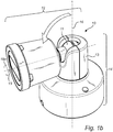
- Figure 1a discloses a system 1 comprising a first part in the form of an attachment part 12 and a second part in the form of a base part 14.
- the attachment part 12 and the base part 14 are coupled by a ball joint 10.
- the ball joint 10 comprises a ball 11 which is arranged in a ball socket 13.
- a general purpose of the construction of the ball joint 10 is to provide a rotational movement and a tilt movement of the ball 10, and thus the associated attachment part 12, relative the ball socket 13, and thus relative the base part 14 in which the ball socket 13 is formed.
- the attachment part 12 is allowed to rotate about a longitudinal axis 16 thereof, as indicated by 16a. Rotation in a direction reverse to the one indicated by 16a is also allowed.
- the attachment part 12 further comprises a housing 17 in which a camera device (not shown) is arranged.
- the camera device may for example be a monitoring camera device, comprising a visual or a thermal image sensor for capturing visual or thermal images of a monitored scene.
- a window 15 is provided in the housing 17 for enabling a field of view outside the housing 17 to the camera device therein.
- the ball socket 13 forms part of the base part 14.
- the base part 14 further comprises a mounting part 18.
- the mounting part 18 is arranged to be attached to a surface, for example a wall.
- the system 1 is thus provided as a camera arrangement which is mountable by the base part 14 and wherein the attachment part 12, comprising the camera device, is rotatable around it longitudinal axis 16 thereof and tiltable relative the base part 14.
- the attachment part 12 has been tilted to a tilt axis 90 degrees from the starting position (illustrated in figure 1a ).
- the camera device's field of view may be adjusted.
- the attachment part 12 is rotatable about a longitudinal axis 19 thereof, as indicated by 19a. Rotation in a direction reverse to the one indicated by 19a is also allowed.
- the system 1 is arranged so that the ball 11 may be fixed in the ball socket 13, meaning that any movement of the ball 11 is prevented.
- the ball 11 may be fixed in the ball socket 13 by wedging the ball 11 in the ball socket 13. This may be achieved by forcing a bottom part of the ball socket 13 upwards such that the ball 11 is forced against upper inner walls of the ball socket 13.
- Other conventional methods for fixing a ball in a ball socket may alternatively be applied.
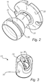
- FIG. 2 is a more detailed illustration of the ball 11.
- An arm 23 and a plate member 22 are provided in connection to the ball 11.
- the plate member 22 may be attached to the housing 17 of the attachment part 12.
- the ball 11 is provided with a groove 20.
- the groove 20 is formed to have ends. In other words, the groove 20 does not extend continuously around the ball 11.
- the groove 20 is provided with ends to form a rotation stop for the ball 11, meaning that the ball 11 should not be allowed to rotate endlessly.
- the purpose of the rotation stop may be explained with reference to figure 4 , where the ball joint 10 is illustrated with a cable 41 arranged therethrough.
- the cable 41 may be provided between a camera device located in the housing 17 of the attachment part 12 and the base part 14. By limiting the rotational movement of the ball 11, rotation of the cable 41 is also limited thus lowering the risk of damaging or even breaking the cable 41 due to the twist.
- the groove 20 is provided to face outwards from the ball 11.
- the groove 20 is thus not provided on an interior surface of the ball 11.
- the groove 20 is arranged essentially around the ball 11 by that the groove 20 extends almost around the ball. Moreover, the groove 20 is arranged essentially equatorially such that a gap 21 is provided between the ends of the groove 20.
- the ball 11 does not need to have the strict shape of a ball but may instead be cut off in one end as in figure 2 .
- Other forms of the ball 11 that are known from ball joint designs are also feasible.
- FIG. 3 is a more detailed illustration of the ball socket 13.
- the ball socket 13 comprises a cavity 31 for receiving the ball 11 in order to form the ball joint 10.
- the ball socket 13 is in this embodiment composed by a first component 32 and a second component 33 which are connected.
- the ball socket 13 is provided with a recess 30.
- the recess 30 is located at an interior surface of the ball socket 13. Specifically, the recess 30 faces inwards and towards the cavity 31.
- the recess 30 is located such that the tilt axis of the ball 11, when the ball 11 is located in the ball socket 13, extends through the recess 30.
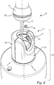
- the ball 11 is arranged in the ball socket 13, more specifically in the cavity 31 of the ball socket 13.
- a coupling element 40 is arranged between the ball 11 and the ball socket 13.
- One part of the coupling element 40 is located in the groove 20 and another part of the coupling element 40 is located in the recess 30.
- the coupling element 40 is formed as a pin element having a first part with a smaller cross-section and a second part with a larger cross-section.
- the first part is (optionally partly) located in the groove 20.
- the second part is (optionally partly) located in the recess 30.
- the coupling element 40 is allowed to move in the groove 20 and in the recess 30.
- the coupling element 40 may move within the groove 20 and within the recess 30.
- the recess 30 is arranged such that the coupling element 40 is allowed to move freely in the plane of the recess 30.
- the recess 30 is arranged to be larger than the part of the coupling element 40 located therein.
- move freely is meant that the coupling element 40 may be moved within the recess 30, i.e. along the plane of the recess 30, without guidance in a particular direction.
- the groove 20 is arranged so as to provide a guided movement for the part of the coupling element 40 located therein.
- the combined arrangement of the recess 30 and the groove 20 with the coupling element 40 located therein allows the ball 11 to move from a first end position to a second end position by a rotational movement.
- the rotation stop referred to above is thereby provided since endless rotational movement of the ball 11 is prevented.
- the components of the ball joint 10 do not need to be assembled according to the arrows and indications of figure 4 .
- the ball 11 is not directly insertable in the cavity 31 when the components 32, 33 of the ball socket 13 are connected.
- the ball joint 10 is instead assembled by arranging and connecting the first and second components 32, 33 around the ball 11 with the coupling element 40 arranged with its respective part in the groove 20 and in the recess 30.
- the ball joint 10 is constructed for providing a simultaneous rotational and tilt movement in at least a selected tilt range.
- the tilt range is at least 0-90 degrees, where the position of the ball 11 in the ball socket 13 at 0 degrees is illustrated in figure 1a and at 90 degrees in figure 1b .
- Figures 5a-5c illustrate three positions for the ball 11 in the ball socket 13 when simultaneously rotated and tilted starting from a first end position at a tilt axis of 0 degrees ( fig. 5a ) to a second end position at a tilt axis of 90 degrees ( fig. 5c).
- Figure 5b illustrates an intermediate position at a tilt axis of about 45 degrees and a rotation of 180 degrees.
- the configuration of the ball joint 10 allows a rotational movement of the ball 11, and thus the associated attachment part 12, of slightly more than 360 degrees, i.e. slightly more than one turn about the ball 11.
- a rotational range of at least 360 degrees is beneficial for allowing the attachment part 12, and thus the camera device in this embodiment, to be rotated to any position while still providing a rotation stop.
- the arrangement of the ball joint 10 also provides that the ball 11 is allowed to be rotated in any tilt angle, at least within a selected range (0-90 degrees in this embodiment).
- the design of the groove 20, the recess 30 and the coupling element 40 will now be explained in detailed with reference to figure 6 .
- the larger cross-section of the coupling element 40 is denoted D and the smaller cross-section of the coupling element 40 is denoted d.
- the coupling element 40 has reached one of the ends of the groove 20. If the rotational movement of the ball 11 was defined only by the groove 20, the ball 11 would not be able to move 360 degrees due to the gap between the groove ends.
- the distance provided between the groove ends by the gap is denoted by b.
- the arrangement of the recess 30 is larger than the cross-section D such that the coupling element 40 is allowed to move within the recess 30 a distance denoted by a.
- the distance a is equal to, as in this example, or larger than the distance b the ball 11 is allowed to rotate the remaining angle up to, or beyond, 360 degrees of rotation, i.e. a full turn or more.
- the recess 30 is arranged so that the coupling element 40 is allowed to move freely in the plane of the recess 30, and thus not only along one direction, the rotational movement of the ball is allowed in multiple tilt angles depending on the form of the recess 30.
- the recess 30 is circular with a diameter being larger than the diameter of the circular cross-section D, rotational movement of the ball 11 is allowed in any tilt angle.
- the shape of recess should be selected so as to allow movement of the coupling element 30 across the recess at least a minimum distance corresponding to the gap between the ends of the groove 20 in every tilt angle of the selected tilt range.
- the arrangements and designs of the coupling element 40, the groove 20, and the recess 30 depend on each other and are selected so as to achieve the desired functions of the movement of the ball 11 within the ball socket 13, i.e. allowing a simultaneous rotational and tilt movement of the ball 11 in a selected tilt range.
- the recess 30 may have different minimum requirements. For example, for a selected tilt range of 0-90 degrees, the recess 30 may be shaped as a three quarters circle. However, a full circle may still be preferred for other reasons such as alleviating the manufacturing process.
- the ball joint comprises a ball 71 which is illustrated in figure 7 .
- the ball 71 is provided with a groove 70.
- an arm 73 and a plate member 72 are provided.
- the ball 71 forms part of an attachment part.
- the groove 70 is arranged helically.
- the groove 70 is arranged essentially around the ball 71.
- the groove 70 extends slightly more than one turn around the ball 71. A rotational movement of the ball 71 of a bit more than one turn, i.e. a slightly more than 360 degrees, is thus provided.
- FIGS 8a-8c illustrate three positions for the ball 71 in a ball socket 75 when simultaneously rotated and tilted starting from a first end position at a tilt axis of 0 degrees ( fig. 8a ) to a second end position at a tilt axis of 90 degrees ( fig. 8c).
- Figure 8b illustrates an intermediate position at a tilt axis of about 45 degrees and a rotation of 180 degrees.
- the ball socket 75 is provided with a recess 80 and a coupling element 90.
- the recess 80 is larger than a part of the coupling element 90 located therein such that the coupling element 90 is allowed to move freely in the plane of the recess 80.
- this shape of the recess 80 provides the possibility to rotate the ball 71 in the ball socket 75, whereby the coupling element 90 is guided by the groove 70, without forcing the ball 71 to tilt sideways.
- tilt sideways is meant tilting in a direction traverse to the main tilt direction that is indicated in figure 8b .
- the ball joint according to the second embodiment provides, besides a rotational movement of more than 360 degrees, an increased freedom when adjusting the ball 71 relative the ball socket 75.
- the shape of the recess 80 being larger than the part of the coupling element 90 located therein, also enables rotational movement of the ball 71 in the ball socket 75 in a selected tilt range.
- the beneficial circular design of the recess 80 provides a simultaneous rotational movement and tilt movement for any tilt angles.
- the coupling elements 40, 90 may be made of steel.
- the other parts of the system, such as the ball 11, 71 and components of the ball socket 13, 75 may be made of aluminum.
- the ball joint as exemplified above may be constructed in a reverse manner wherein the attachment part (the first part) comprises the ball socket and the base part (the second part) comprises the ball.
- the person skilled in the art realizes that the present invention by no means is limited to the preferred embodiments described above. On the contrary, many modifications and variations are possible within the scope of the appended claims.
- the concept of providing a combined arrangement of a groove in a ball, a recess in an interior surface of a ball socket and a coupling element so as to enable simultaneous rotational and tilt movement of the ball relative the ball socket may be applied to ball joints of various otherwise conventional designs.
- the ball joint may be applied in various applications where it is desired to provide the above disclosed advantageous effects of the ball joint.
Landscapes
- Engineering & Computer Science (AREA)
- General Engineering & Computer Science (AREA)
- Mechanical Engineering (AREA)
- Physics & Mathematics (AREA)
- General Physics & Mathematics (AREA)
- Pivots And Pivotal Connections (AREA)
- Finger-Pressure Massage (AREA)
Claims (12)
- Joint sphérique (10) destiné au couplage d'une partie d'attache (12) sur une partie de base (14, 74) de sorte que la partie d'attache (12) peut être inclinée par rapport à la partie de base (14, 74) et de sorte que la partie d'attache (12) peut être mise en rotation autour d'un axe longitudinal (16, 19) de celle-ci, et étant telle que, lorsqu'utilisée en combinaison avec un câble ou un élément similaire, le câble ou l'élément similaire est agencé à travers ledit joint sphérique,
le joint sphérique (10) comprenant :une bille (11, 71) associée à ladite partie d'attache (12) et munie d'une rainure (20, 70) possédant des extrémités, lesdites extrémités limitant la rotation autour dudit axe longitudinal (19) de la partie d'attache (12) ;une rotule (13, 75) formée dans la partie de base (14, 74) et munie d'un renfoncement (30, 80) ; etun élément de couplage (40, 90) ;dans lequel la bille (11, 71) et l'élément de couplage (40, 90) sont agencés dans la rotule (13, 75) de sorte qu'une partie de l'élément de couplage (40, 90) est située dans la rainure (20, 70) et une autre partie de l'élément de couplage (40, 90) est située dans le renfoncement (30, 80) selon lequel un mouvement de la bille (11, 71) est restreint ;dans lequel le renfoncement (30, 80) et la rainure (20, 70) sont agencés de sorte que l'on permet à la partie respective de l'élément de couplage (40, 90) de se déplacer dans ceux-ci ;
etdans lequel le renfoncement (30, 80) est plus large que la partie provenant de l'élément de couplage (40, 90) situé dans celui-ci de sorte que l'on permet à l'élément de couplage (40, 90) de se déplacer librement dans le plan du renfoncement (30, 80), caractérisé en ce que la rainure (20, 70) s'étend de manière essentiellement équatoriale d'un tour autour de la bille (11, 71), et en ce que l'agencement combiné de la rainure (20, 70), du renfoncement (30, 80), et de l'élément de couplage (40, 90) permet à la bille (11, 71) de se déplacer à partir d'une première position d'extrémité vers une seconde position d'extrémité par un mouvement rotationnel de plus de 360°. - Joint sphérique selon la revendication 1, dans lequel la rainure (20) est agencée de manière équatoriale de sorte qu'un espace (21) est fourni entre les extrémités de la rainure (20), et dans lequel le renfoncement (30) est agencé pour permettre à la partie de l'élément de couplage (40) située dans celui-ci de se déplacer d'une distance correspondant à celle de l'espace.
- Joint sphérique selon la revendication 1 ou la revendication 2, dans lequel le renfoncement (30) est agencé de sorte que l'axe d'inclinaison de la bille (11) s'étend à travers le renfoncement (30).
- Joint sphérique selon la revendication 1, dans lequel la rainure (70) est agencée de manière hélicoïdale.
- Joint sphérique selon la revendication 4, dans lequel la rainure (70 parenthèse est agencée au moins autour de la bille (71).
- Joint sphérique selon l'une quelconque des revendications 1 à 5, dans lequel le renfoncement (30, 80) est circulaire.
- Joint sphérique selon la revendication 6, dans lequel le renfoncement circulaire (30, 80) est agencé de sorte que l'acte inclinaison de la bille (11, 71) s'étend à travers le centre du renfoncement (30).
- Joint sphérique selon l'une quelconque des revendications 1 à 7, dans lequel la partie d'attache (12) peut être inclinée à au moins 90° par rapport à la partie de base (14, 74).
- Joint sphérique selon l'une quelconque des revendications 1 à 8, dans lequel l'élément de couplage (40, 90) est fait d'acier.
- Joint sphérique selon l'une quelconque des revendications 1 à 9, dans lequel la partie d'attache consiste en une partie d'un dispositif de caméra de surveillance, d'un dispositif d'éclairage, ou d'un dispositif de haut-parleur.
- Système comprenant une partie d'attache (12) et une partie de base (14, 74) qui sont couplées par le joint sphérique (10) de sorte que la partie d'attache (12) peut être inclinée par rapport à la partie de base (14, 74) et de sorte que la partie d'attache (14, 74) peut être mise en rotation autour d'un axe longitudinal (16, 19) de celle-ci, dans lequel le joint sphérique est agencé selon l'une quelconque des revendications 1 à 10.
- Système selon la revendication 11, comprenant en outre un dispositif de caméra de surveillance comprenant la partie d'attache (12).
Priority Applications (6)
| Application Number | Priority Date | Filing Date | Title |
|---|---|---|---|
| EP16160342.8A EP3220036B1 (fr) | 2016-03-15 | 2016-03-15 | Joint sphérique |
| CN201710107514.0A CN107191471B (zh) | 2016-03-15 | 2017-02-27 | 球接头及包括该球接头的系统 |
| TW106107334A TWI702361B (zh) | 2016-03-15 | 2017-03-07 | 球形接頭 |
| JP2017044261A JP6545209B2 (ja) | 2016-03-15 | 2017-03-08 | ボール継手 |
| KR1020170030788A KR101999819B1 (ko) | 2016-03-15 | 2017-03-10 | 볼 조인트 |
| US15/457,551 US10082726B2 (en) | 2016-03-15 | 2017-03-13 | Ball joint |
Applications Claiming Priority (1)
| Application Number | Priority Date | Filing Date | Title |
|---|---|---|---|
| EP16160342.8A EP3220036B1 (fr) | 2016-03-15 | 2016-03-15 | Joint sphérique |
Publications (2)
| Publication Number | Publication Date |
|---|---|
| EP3220036A1 EP3220036A1 (fr) | 2017-09-20 |
| EP3220036B1 true EP3220036B1 (fr) | 2018-06-06 |
Family
ID=55637169
Family Applications (1)
| Application Number | Title | Priority Date | Filing Date |
|---|---|---|---|
| EP16160342.8A Active EP3220036B1 (fr) | 2016-03-15 | 2016-03-15 | Joint sphérique |
Country Status (6)
| Country | Link |
|---|---|
| US (1) | US10082726B2 (fr) |
| EP (1) | EP3220036B1 (fr) |
| JP (1) | JP6545209B2 (fr) |
| KR (1) | KR101999819B1 (fr) |
| CN (1) | CN107191471B (fr) |
| TW (1) | TWI702361B (fr) |
Cited By (1)
| Publication number | Priority date | Publication date | Assignee | Title |
|---|---|---|---|---|
| WO2022046883A1 (fr) * | 2020-08-25 | 2022-03-03 | Axon Enterprise, Inc. | Joint sphérique présentant une capacité de nivellement et de panoramique |
Families Citing this family (14)
| Publication number | Priority date | Publication date | Assignee | Title |
|---|---|---|---|---|
| EP3352829B1 (fr) | 2015-09-23 | 2022-12-28 | ResMed Pty Ltd | Ensemble coudé |
| USD822853S1 (en) * | 2015-11-20 | 2018-07-10 | Jad Honein | Cone handrail support |
| EP3246615B1 (fr) * | 2016-05-20 | 2018-05-02 | Axis AB | Ensemble de montage |
| USD881968S1 (en) * | 2018-01-15 | 2020-04-21 | Axis Ab | Camera |
| US20190234535A1 (en) * | 2018-01-31 | 2019-08-01 | A. Raymond Et Cie. | Ball And Socket Fastener For Attaching Components |
| USD956126S1 (en) * | 2019-07-18 | 2022-06-28 | Ario Technologies, Inc. | Electronics device mount |
| WO2021188222A2 (fr) * | 2020-02-06 | 2021-09-23 | Galvion Ltd. | Système de vision pour casque intégré renforcé |
| USD928220S1 (en) * | 2020-04-29 | 2021-08-17 | Andy Liang | Gimbal spherical bracket |
| US11187400B1 (en) * | 2021-01-21 | 2021-11-30 | Ubicquia, Inc. | Floating connector |
| KR102494475B1 (ko) | 2021-04-06 | 2023-02-07 | (주)아이엠지티 | 초음파 헤드 |
| US20220349498A1 (en) * | 2021-04-29 | 2022-11-03 | APG Vision LLC | Ball Mount with Integrated Cable Gland |
| CA3218744A1 (fr) | 2021-05-12 | 2022-11-17 | Elaine Violet CRAIGIE | Systeme de formage d'un casque embouti et procede associe |
| CN113410644B (zh) * | 2021-06-10 | 2022-09-20 | 深圳市英佳创电子科技有限公司 | 一种室内全向天线 |
| WO2023072821A1 (fr) * | 2021-10-28 | 2023-05-04 | Signify Holding B.V. | Dispositif d'éclairage directionnel |
Citations (1)
| Publication number | Priority date | Publication date | Assignee | Title |
|---|---|---|---|---|
| US20040195469A1 (en) * | 2002-11-20 | 2004-10-07 | Kabushiki Kaisha Audio-Technica | Microphone support |
Family Cites Families (20)
| Publication number | Priority date | Publication date | Assignee | Title |
|---|---|---|---|---|
| US2910310A (en) * | 1957-12-06 | 1959-10-27 | Rudolph A Mulac | Ball and socket swivel for an electric light receptacle |
| US3034809A (en) * | 1960-08-08 | 1962-05-15 | Greenberg Harold Jay | Universal ball and socket joint |
| US3186736A (en) * | 1962-10-02 | 1965-06-01 | Warshawsky Jerome | Limited universal swivel joint fittings for electric conduits |
| US3312482A (en) | 1964-12-14 | 1967-04-04 | Internat Commodities Inc | Swivel assembly rotatable through more than one revolution |
| DD114664A1 (fr) | 1974-10-11 | 1975-08-12 | ||
| US4225260A (en) * | 1979-03-02 | 1980-09-30 | Gulf & Western Manufacturing Company | Tie rod ball joint construction |
| US4322098A (en) * | 1979-05-11 | 1982-03-30 | I. W. Industries, Inc. | Swivel joint |
| US4515336A (en) * | 1983-04-14 | 1985-05-07 | Opcon, Inc. | Ball and socket mount for optical sensing system source and/or detector devices |
| US4842308A (en) | 1988-06-23 | 1989-06-27 | Australux North America Limited | Rotation limiting ball-joint conduit apparatus |
| DE4231438A1 (de) * | 1992-09-19 | 1994-03-24 | Skf Gleitlager Gmbh | Gelenklager mit Drehbegrenzung |
| JP2993328B2 (ja) * | 1993-09-10 | 1999-12-20 | 日産自動車株式会社 | ボールジョイント部構造 |
| US5569089A (en) * | 1993-10-28 | 1996-10-29 | Signorelli; Richard L. | Universal joint construction |
| DE10338498A1 (de) | 2002-05-03 | 2005-03-17 | Carl Zeiss | Gelenkanordnung |
| ITPD20050143A1 (it) * | 2005-05-18 | 2006-11-19 | Lino Manfrotto & Co Spa | Supporto per attrezzature video fotografiche |
| JP2009079632A (ja) * | 2007-09-25 | 2009-04-16 | Nobuyuki Sugimoto | 揺動機構 |
| US8267361B1 (en) * | 2007-10-18 | 2012-09-18 | Acratech, Inc. | Attachment to a long lens support device which functions as both a ball head and a gimble head |
| US8120895B2 (en) | 2010-03-11 | 2012-02-21 | Garmin Switzerland Gmbh | Mounting assembly having a base with an inner ball positioned within a hollow outer ball |
| JP5749919B2 (ja) * | 2010-11-19 | 2015-07-15 | 住友精密工業株式会社 | 6方向指向装置 |
| TWM452302U (zh) * | 2012-09-24 | 2013-05-01 | cun-yu Huang | 方便指向調整之感應燈結構 |
| CN204327744U (zh) * | 2014-12-01 | 2015-05-13 | 杭州电子科技大学 | 可检测空间回转角的球铰链 |
-
2016
- 2016-03-15 EP EP16160342.8A patent/EP3220036B1/fr active Active
-
2017
- 2017-02-27 CN CN201710107514.0A patent/CN107191471B/zh active Active
- 2017-03-07 TW TW106107334A patent/TWI702361B/zh active
- 2017-03-08 JP JP2017044261A patent/JP6545209B2/ja active Active
- 2017-03-10 KR KR1020170030788A patent/KR101999819B1/ko active IP Right Grant
- 2017-03-13 US US15/457,551 patent/US10082726B2/en active Active
Patent Citations (1)
| Publication number | Priority date | Publication date | Assignee | Title |
|---|---|---|---|---|
| US20040195469A1 (en) * | 2002-11-20 | 2004-10-07 | Kabushiki Kaisha Audio-Technica | Microphone support |
Cited By (1)
| Publication number | Priority date | Publication date | Assignee | Title |
|---|---|---|---|---|
| WO2022046883A1 (fr) * | 2020-08-25 | 2022-03-03 | Axon Enterprise, Inc. | Joint sphérique présentant une capacité de nivellement et de panoramique |
Also Published As
| Publication number | Publication date |
|---|---|
| JP6545209B2 (ja) | 2019-07-17 |
| JP2017207201A (ja) | 2017-11-24 |
| KR20170107385A (ko) | 2017-09-25 |
| TWI702361B (zh) | 2020-08-21 |
| US10082726B2 (en) | 2018-09-25 |
| US20170269460A1 (en) | 2017-09-21 |
| EP3220036A1 (fr) | 2017-09-20 |
| KR101999819B1 (ko) | 2019-07-12 |
| TW201736745A (zh) | 2017-10-16 |
| CN107191471A (zh) | 2017-09-22 |
| CN107191471B (zh) | 2019-05-21 |
Similar Documents
| Publication | Publication Date | Title |
|---|---|---|
| EP3220036B1 (fr) | Joint sphérique | |
| KR101863851B1 (ko) | 장착 어셈블리 | |
| US11196900B2 (en) | Multi-headed adjustable camera | |
| EP1788800A1 (fr) | Dispositif d'installation de caméra | |
| US5404182A (en) | Swivel chassis | |
| EP3562140B1 (fr) | Système de caméra panoramique basculante sur deux axes conçu pour maintenir un niveau d'image lors d'un montage au mur ou au plafond | |
| US10070024B2 (en) | Arrangement for supporting a monitoring camera and a method for assembling the arrangement | |
| KR200481843Y1 (ko) | Cctv카메라 설치장치 | |
| US10248008B2 (en) | Removable hinge | |
| US6070835A (en) | Ball-compression grommet | |
| US9920875B2 (en) | Articulating arm | |
| TWI686659B (zh) | 攝像機機殼裝置 | |
| JP4749441B2 (ja) | 手摺の自在連結具 | |
| KR101547454B1 (ko) | 파노라마 기능을 구비한 볼 헤드용 다기능 볼 | |
| KR101148994B1 (ko) | 감시카메라용 각도조절장치 | |
| EP2984379B1 (fr) | Dispositif de couplage destiné au couplage d'un accessoire à un bras porteur, tel qu'un bras porteur et une dispositif de maintien | |
| JP3539807B2 (ja) | フレキシブルコネクタ | |
| KR100697672B1 (ko) | 카메라 틸팅장치 | |
| US20190132664A1 (en) | Disconnectable Connector with Provisions for Motion in Two Axes | |
| US20240000179A1 (en) | Modular vision system, particularly for helmets and the like | |
| CN213934503U (zh) | 户外相机塑胶壳 | |
| EP3208509A1 (fr) | Caméra de sécurité avec support mobile |
Legal Events
| Date | Code | Title | Description |
|---|---|---|---|
| STAA | Information on the status of an ep patent application or granted ep patent |
Free format text: STATUS: EXAMINATION IS IN PROGRESS |
|
| PUAI | Public reference made under article 153(3) epc to a published international application that has entered the european phase |
Free format text: ORIGINAL CODE: 0009012 |
|
| 17P | Request for examination filed |
Effective date: 20161128 |
|
| AK | Designated contracting states |
Kind code of ref document: A1 Designated state(s): AL AT BE BG CH CY CZ DE DK EE ES FI FR GB GR HR HU IE IS IT LI LT LU LV MC MK MT NL NO PL PT RO RS SE SI SK SM TR |
|
| AX | Request for extension of the european patent |
Extension state: BA ME |
|
| REG | Reference to a national code |
Ref country code: DE Ref legal event code: R079 Ref document number: 602016003261 Country of ref document: DE Free format text: PREVIOUS MAIN CLASS: F16M0011140000 Ipc: F16M0013020000 |
|
| RIC1 | Information provided on ipc code assigned before grant |
Ipc: F16M 11/14 20060101ALI20171122BHEP Ipc: G03B 17/56 20060101ALI20171122BHEP Ipc: F16C 11/06 20060101ALI20171122BHEP Ipc: F21V 21/29 20060101ALI20171122BHEP Ipc: F16M 13/02 20060101AFI20171122BHEP |
|
| GRAP | Despatch of communication of intention to grant a patent |
Free format text: ORIGINAL CODE: EPIDOSNIGR1 |
|
| STAA | Information on the status of an ep patent application or granted ep patent |
Free format text: STATUS: GRANT OF PATENT IS INTENDED |
|
| INTG | Intention to grant announced |
Effective date: 20180118 |
|
| GRAS | Grant fee paid |
Free format text: ORIGINAL CODE: EPIDOSNIGR3 |
|
| GRAA | (expected) grant |
Free format text: ORIGINAL CODE: 0009210 |
|
| STAA | Information on the status of an ep patent application or granted ep patent |
Free format text: STATUS: THE PATENT HAS BEEN GRANTED |
|
| AK | Designated contracting states |
Kind code of ref document: B1 Designated state(s): AL AT BE BG CH CY CZ DE DK EE ES FI FR GB GR HR HU IE IS IT LI LT LU LV MC MK MT NL NO PL PT RO RS SE SI SK SM TR |
|
| REG | Reference to a national code |
Ref country code: GB Ref legal event code: FG4D |
|
| REG | Reference to a national code |
Ref country code: CH Ref legal event code: EP Ref country code: AT Ref legal event code: REF Ref document number: 1006483 Country of ref document: AT Kind code of ref document: T Effective date: 20180615 |
|
| REG | Reference to a national code |
Ref country code: IE Ref legal event code: FG4D |
|
| REG | Reference to a national code |
Ref country code: SE Ref legal event code: TRGR |
|
| REG | Reference to a national code |
Ref country code: DE Ref legal event code: R096 Ref document number: 602016003261 Country of ref document: DE |
|
| REG | Reference to a national code |
Ref country code: NL Ref legal event code: MP Effective date: 20180606 |
|
| REG | Reference to a national code |
Ref country code: LT Ref legal event code: MG4D |
|
| PG25 | Lapsed in a contracting state [announced via postgrant information from national office to epo] |
Ref country code: FI Free format text: LAPSE BECAUSE OF FAILURE TO SUBMIT A TRANSLATION OF THE DESCRIPTION OR TO PAY THE FEE WITHIN THE PRESCRIBED TIME-LIMIT Effective date: 20180606 Ref country code: NO Free format text: LAPSE BECAUSE OF FAILURE TO SUBMIT A TRANSLATION OF THE DESCRIPTION OR TO PAY THE FEE WITHIN THE PRESCRIBED TIME-LIMIT Effective date: 20180906 Ref country code: BG Free format text: LAPSE BECAUSE OF FAILURE TO SUBMIT A TRANSLATION OF THE DESCRIPTION OR TO PAY THE FEE WITHIN THE PRESCRIBED TIME-LIMIT Effective date: 20180906 Ref country code: LT Free format text: LAPSE BECAUSE OF FAILURE TO SUBMIT A TRANSLATION OF THE DESCRIPTION OR TO PAY THE FEE WITHIN THE PRESCRIBED TIME-LIMIT Effective date: 20180606 Ref country code: ES Free format text: LAPSE BECAUSE OF FAILURE TO SUBMIT A TRANSLATION OF THE DESCRIPTION OR TO PAY THE FEE WITHIN THE PRESCRIBED TIME-LIMIT Effective date: 20180606 Ref country code: CY Free format text: LAPSE BECAUSE OF FAILURE TO SUBMIT A TRANSLATION OF THE DESCRIPTION OR TO PAY THE FEE WITHIN THE PRESCRIBED TIME-LIMIT Effective date: 20180606 |
|
| PG25 | Lapsed in a contracting state [announced via postgrant information from national office to epo] |
Ref country code: RS Free format text: LAPSE BECAUSE OF FAILURE TO SUBMIT A TRANSLATION OF THE DESCRIPTION OR TO PAY THE FEE WITHIN THE PRESCRIBED TIME-LIMIT Effective date: 20180606 Ref country code: HR Free format text: LAPSE BECAUSE OF FAILURE TO SUBMIT A TRANSLATION OF THE DESCRIPTION OR TO PAY THE FEE WITHIN THE PRESCRIBED TIME-LIMIT Effective date: 20180606 Ref country code: GR Free format text: LAPSE BECAUSE OF FAILURE TO SUBMIT A TRANSLATION OF THE DESCRIPTION OR TO PAY THE FEE WITHIN THE PRESCRIBED TIME-LIMIT Effective date: 20180907 Ref country code: LV Free format text: LAPSE BECAUSE OF FAILURE TO SUBMIT A TRANSLATION OF THE DESCRIPTION OR TO PAY THE FEE WITHIN THE PRESCRIBED TIME-LIMIT Effective date: 20180606 |
|
| REG | Reference to a national code |
Ref country code: AT Ref legal event code: MK05 Ref document number: 1006483 Country of ref document: AT Kind code of ref document: T Effective date: 20180606 |
|
| PG25 | Lapsed in a contracting state [announced via postgrant information from national office to epo] |
Ref country code: NL Free format text: LAPSE BECAUSE OF FAILURE TO SUBMIT A TRANSLATION OF THE DESCRIPTION OR TO PAY THE FEE WITHIN THE PRESCRIBED TIME-LIMIT Effective date: 20180606 |
|
| PG25 | Lapsed in a contracting state [announced via postgrant information from national office to epo] |
Ref country code: IS Free format text: LAPSE BECAUSE OF FAILURE TO SUBMIT A TRANSLATION OF THE DESCRIPTION OR TO PAY THE FEE WITHIN THE PRESCRIBED TIME-LIMIT Effective date: 20181006 Ref country code: PL Free format text: LAPSE BECAUSE OF FAILURE TO SUBMIT A TRANSLATION OF THE DESCRIPTION OR TO PAY THE FEE WITHIN THE PRESCRIBED TIME-LIMIT Effective date: 20180606 Ref country code: EE Free format text: LAPSE BECAUSE OF FAILURE TO SUBMIT A TRANSLATION OF THE DESCRIPTION OR TO PAY THE FEE WITHIN THE PRESCRIBED TIME-LIMIT Effective date: 20180606 Ref country code: AT Free format text: LAPSE BECAUSE OF FAILURE TO SUBMIT A TRANSLATION OF THE DESCRIPTION OR TO PAY THE FEE WITHIN THE PRESCRIBED TIME-LIMIT Effective date: 20180606 Ref country code: CZ Free format text: LAPSE BECAUSE OF FAILURE TO SUBMIT A TRANSLATION OF THE DESCRIPTION OR TO PAY THE FEE WITHIN THE PRESCRIBED TIME-LIMIT Effective date: 20180606 Ref country code: RO Free format text: LAPSE BECAUSE OF FAILURE TO SUBMIT A TRANSLATION OF THE DESCRIPTION OR TO PAY THE FEE WITHIN THE PRESCRIBED TIME-LIMIT Effective date: 20180606 Ref country code: SK Free format text: LAPSE BECAUSE OF FAILURE TO SUBMIT A TRANSLATION OF THE DESCRIPTION OR TO PAY THE FEE WITHIN THE PRESCRIBED TIME-LIMIT Effective date: 20180606 |
|
| PG25 | Lapsed in a contracting state [announced via postgrant information from national office to epo] |
Ref country code: SM Free format text: LAPSE BECAUSE OF FAILURE TO SUBMIT A TRANSLATION OF THE DESCRIPTION OR TO PAY THE FEE WITHIN THE PRESCRIBED TIME-LIMIT Effective date: 20180606 Ref country code: IT Free format text: LAPSE BECAUSE OF FAILURE TO SUBMIT A TRANSLATION OF THE DESCRIPTION OR TO PAY THE FEE WITHIN THE PRESCRIBED TIME-LIMIT Effective date: 20180606 |
|
| REG | Reference to a national code |
Ref country code: DE Ref legal event code: R097 Ref document number: 602016003261 Country of ref document: DE |
|
| PLBE | No opposition filed within time limit |
Free format text: ORIGINAL CODE: 0009261 |
|
| STAA | Information on the status of an ep patent application or granted ep patent |
Free format text: STATUS: NO OPPOSITION FILED WITHIN TIME LIMIT |
|
| 26N | No opposition filed |
Effective date: 20190307 |
|
| PG25 | Lapsed in a contracting state [announced via postgrant information from national office to epo] |
Ref country code: DK Free format text: LAPSE BECAUSE OF FAILURE TO SUBMIT A TRANSLATION OF THE DESCRIPTION OR TO PAY THE FEE WITHIN THE PRESCRIBED TIME-LIMIT Effective date: 20180606 |
|
| PG25 | Lapsed in a contracting state [announced via postgrant information from national office to epo] |
Ref country code: MC Free format text: LAPSE BECAUSE OF FAILURE TO SUBMIT A TRANSLATION OF THE DESCRIPTION OR TO PAY THE FEE WITHIN THE PRESCRIBED TIME-LIMIT Effective date: 20180606 |
|
| REG | Reference to a national code |
Ref country code: CH Ref legal event code: PL |
|
| PG25 | Lapsed in a contracting state [announced via postgrant information from national office to epo] |
Ref country code: LU Free format text: LAPSE BECAUSE OF NON-PAYMENT OF DUE FEES Effective date: 20190315 Ref country code: AL Free format text: LAPSE BECAUSE OF FAILURE TO SUBMIT A TRANSLATION OF THE DESCRIPTION OR TO PAY THE FEE WITHIN THE PRESCRIBED TIME-LIMIT Effective date: 20180606 |
|
| REG | Reference to a national code |
Ref country code: BE Ref legal event code: MM Effective date: 20190331 |
|
| PG25 | Lapsed in a contracting state [announced via postgrant information from national office to epo] |
Ref country code: LI Free format text: LAPSE BECAUSE OF NON-PAYMENT OF DUE FEES Effective date: 20190331 Ref country code: IE Free format text: LAPSE BECAUSE OF NON-PAYMENT OF DUE FEES Effective date: 20190315 Ref country code: CH Free format text: LAPSE BECAUSE OF NON-PAYMENT OF DUE FEES Effective date: 20190331 |
|
| PG25 | Lapsed in a contracting state [announced via postgrant information from national office to epo] |
Ref country code: BE Free format text: LAPSE BECAUSE OF NON-PAYMENT OF DUE FEES Effective date: 20190331 |
|
| PG25 | Lapsed in a contracting state [announced via postgrant information from national office to epo] |
Ref country code: TR Free format text: LAPSE BECAUSE OF FAILURE TO SUBMIT A TRANSLATION OF THE DESCRIPTION OR TO PAY THE FEE WITHIN THE PRESCRIBED TIME-LIMIT Effective date: 20180606 |
|
| PG25 | Lapsed in a contracting state [announced via postgrant information from national office to epo] |
Ref country code: MT Free format text: LAPSE BECAUSE OF NON-PAYMENT OF DUE FEES Effective date: 20190315 Ref country code: PT Free format text: LAPSE BECAUSE OF FAILURE TO SUBMIT A TRANSLATION OF THE DESCRIPTION OR TO PAY THE FEE WITHIN THE PRESCRIBED TIME-LIMIT Effective date: 20181008 |
|
| PG25 | Lapsed in a contracting state [announced via postgrant information from national office to epo] |
Ref country code: HU Free format text: LAPSE BECAUSE OF FAILURE TO SUBMIT A TRANSLATION OF THE DESCRIPTION OR TO PAY THE FEE WITHIN THE PRESCRIBED TIME-LIMIT; INVALID AB INITIO Effective date: 20160315 |
|
| PG25 | Lapsed in a contracting state [announced via postgrant information from national office to epo] |
Ref country code: SI Free format text: LAPSE BECAUSE OF FAILURE TO SUBMIT A TRANSLATION OF THE DESCRIPTION OR TO PAY THE FEE WITHIN THE PRESCRIBED TIME-LIMIT Effective date: 20180606 |
|
| PG25 | Lapsed in a contracting state [announced via postgrant information from national office to epo] |
Ref country code: MK Free format text: LAPSE BECAUSE OF FAILURE TO SUBMIT A TRANSLATION OF THE DESCRIPTION OR TO PAY THE FEE WITHIN THE PRESCRIBED TIME-LIMIT Effective date: 20180606 |
|
| PGFP | Annual fee paid to national office [announced via postgrant information from national office to epo] |
Ref country code: FR Payment date: 20230222 Year of fee payment: 8 |
|
| PGFP | Annual fee paid to national office [announced via postgrant information from national office to epo] |
Ref country code: SE Payment date: 20230222 Year of fee payment: 8 |
|
| P01 | Opt-out of the competence of the unified patent court (upc) registered |
Effective date: 20230505 |
|
| PGFP | Annual fee paid to national office [announced via postgrant information from national office to epo] |
Ref country code: DE Payment date: 20240220 Year of fee payment: 9 Ref country code: GB Payment date: 20240220 Year of fee payment: 9 |