EP3219920A1 - Component for a turbine engine with a film hole - Google Patents
Component for a turbine engine with a film hole Download PDFInfo
- Publication number
- EP3219920A1 EP3219920A1 EP17161186.6A EP17161186A EP3219920A1 EP 3219920 A1 EP3219920 A1 EP 3219920A1 EP 17161186 A EP17161186 A EP 17161186A EP 3219920 A1 EP3219920 A1 EP 3219920A1
- Authority
- EP
- European Patent Office
- Prior art keywords
- engine
- component
- inner dimension
- hole
- predetermined inner
- Prior art date
- Legal status (The legal status is an assumption and is not a legal conclusion. Google has not performed a legal analysis and makes no representation as to the accuracy of the status listed.)
- Withdrawn
Links
Images

Classifications
-
- F—MECHANICAL ENGINEERING; LIGHTING; HEATING; WEAPONS; BLASTING
- F01—MACHINES OR ENGINES IN GENERAL; ENGINE PLANTS IN GENERAL; STEAM ENGINES
- F01D—NON-POSITIVE DISPLACEMENT MACHINES OR ENGINES, e.g. STEAM TURBINES
- F01D5/00—Blades; Blade-carrying members; Heating, heat-insulating, cooling or antivibration means on the blades or the members
- F01D5/12—Blades
- F01D5/14—Form or construction
- F01D5/18—Hollow blades, i.e. blades with cooling or heating channels or cavities; Heating, heat-insulating or cooling means on blades
- F01D5/186—Film cooling
-
- F—MECHANICAL ENGINEERING; LIGHTING; HEATING; WEAPONS; BLASTING
- F01—MACHINES OR ENGINES IN GENERAL; ENGINE PLANTS IN GENERAL; STEAM ENGINES
- F01D—NON-POSITIVE DISPLACEMENT MACHINES OR ENGINES, e.g. STEAM TURBINES
- F01D25/00—Component parts, details, or accessories, not provided for in, or of interest apart from, other groups
- F01D25/08—Cooling; Heating; Heat-insulation
- F01D25/12—Cooling
-
- F—MECHANICAL ENGINEERING; LIGHTING; HEATING; WEAPONS; BLASTING
- F01—MACHINES OR ENGINES IN GENERAL; ENGINE PLANTS IN GENERAL; STEAM ENGINES
- F01D—NON-POSITIVE DISPLACEMENT MACHINES OR ENGINES, e.g. STEAM TURBINES
- F01D25/00—Component parts, details, or accessories, not provided for in, or of interest apart from, other groups
- F01D25/08—Cooling; Heating; Heat-insulation
- F01D25/14—Casings modified therefor
-
- F—MECHANICAL ENGINEERING; LIGHTING; HEATING; WEAPONS; BLASTING
- F01—MACHINES OR ENGINES IN GENERAL; ENGINE PLANTS IN GENERAL; STEAM ENGINES
- F01D—NON-POSITIVE DISPLACEMENT MACHINES OR ENGINES, e.g. STEAM TURBINES
- F01D5/00—Blades; Blade-carrying members; Heating, heat-insulating, cooling or antivibration means on the blades or the members
- F01D5/12—Blades
- F01D5/28—Selecting particular materials; Particular measures relating thereto; Measures against erosion or corrosion
- F01D5/288—Protective coatings for blades
-
- F—MECHANICAL ENGINEERING; LIGHTING; HEATING; WEAPONS; BLASTING
- F01—MACHINES OR ENGINES IN GENERAL; ENGINE PLANTS IN GENERAL; STEAM ENGINES
- F01D—NON-POSITIVE DISPLACEMENT MACHINES OR ENGINES, e.g. STEAM TURBINES
- F01D9/00—Stators
- F01D9/02—Nozzles; Nozzle boxes; Stator blades; Guide conduits, e.g. individual nozzles
- F01D9/04—Nozzles; Nozzle boxes; Stator blades; Guide conduits, e.g. individual nozzles forming ring or sector
- F01D9/041—Nozzles; Nozzle boxes; Stator blades; Guide conduits, e.g. individual nozzles forming ring or sector using blades
-
- F—MECHANICAL ENGINEERING; LIGHTING; HEATING; WEAPONS; BLASTING
- F23—COMBUSTION APPARATUS; COMBUSTION PROCESSES
- F23R—GENERATING COMBUSTION PRODUCTS OF HIGH PRESSURE OR HIGH VELOCITY, e.g. GAS-TURBINE COMBUSTION CHAMBERS
- F23R3/00—Continuous combustion chambers using liquid or gaseous fuel
- F23R3/002—Wall structures
-
- F—MECHANICAL ENGINEERING; LIGHTING; HEATING; WEAPONS; BLASTING
- F23—COMBUSTION APPARATUS; COMBUSTION PROCESSES
- F23R—GENERATING COMBUSTION PRODUCTS OF HIGH PRESSURE OR HIGH VELOCITY, e.g. GAS-TURBINE COMBUSTION CHAMBERS
- F23R3/00—Continuous combustion chambers using liquid or gaseous fuel
- F23R3/42—Continuous combustion chambers using liquid or gaseous fuel characterised by the arrangement or form of the flame tubes or combustion chambers
- F23R3/58—Cyclone or vortex type combustion chambers
-
- F—MECHANICAL ENGINEERING; LIGHTING; HEATING; WEAPONS; BLASTING
- F05—INDEXING SCHEMES RELATING TO ENGINES OR PUMPS IN VARIOUS SUBCLASSES OF CLASSES F01-F04
- F05D—INDEXING SCHEME FOR ASPECTS RELATING TO NON-POSITIVE-DISPLACEMENT MACHINES OR ENGINES, GAS-TURBINES OR JET-PROPULSION PLANTS
- F05D2220/00—Application
- F05D2220/30—Application in turbines
-
- F—MECHANICAL ENGINEERING; LIGHTING; HEATING; WEAPONS; BLASTING
- F05—INDEXING SCHEMES RELATING TO ENGINES OR PUMPS IN VARIOUS SUBCLASSES OF CLASSES F01-F04
- F05D—INDEXING SCHEME FOR ASPECTS RELATING TO NON-POSITIVE-DISPLACEMENT MACHINES OR ENGINES, GAS-TURBINES OR JET-PROPULSION PLANTS
- F05D2230/00—Manufacture
- F05D2230/10—Manufacture by removing material
- F05D2230/12—Manufacture by removing material by spark erosion methods
-
- F—MECHANICAL ENGINEERING; LIGHTING; HEATING; WEAPONS; BLASTING
- F05—INDEXING SCHEMES RELATING TO ENGINES OR PUMPS IN VARIOUS SUBCLASSES OF CLASSES F01-F04
- F05D—INDEXING SCHEME FOR ASPECTS RELATING TO NON-POSITIVE-DISPLACEMENT MACHINES OR ENGINES, GAS-TURBINES OR JET-PROPULSION PLANTS
- F05D2230/00—Manufacture
- F05D2230/10—Manufacture by removing material
- F05D2230/13—Manufacture by removing material using lasers
-
- F—MECHANICAL ENGINEERING; LIGHTING; HEATING; WEAPONS; BLASTING
- F05—INDEXING SCHEMES RELATING TO ENGINES OR PUMPS IN VARIOUS SUBCLASSES OF CLASSES F01-F04
- F05D—INDEXING SCHEME FOR ASPECTS RELATING TO NON-POSITIVE-DISPLACEMENT MACHINES OR ENGINES, GAS-TURBINES OR JET-PROPULSION PLANTS
- F05D2230/00—Manufacture
- F05D2230/20—Manufacture essentially without removing material
- F05D2230/21—Manufacture essentially without removing material by casting
-
- F—MECHANICAL ENGINEERING; LIGHTING; HEATING; WEAPONS; BLASTING
- F05—INDEXING SCHEMES RELATING TO ENGINES OR PUMPS IN VARIOUS SUBCLASSES OF CLASSES F01-F04
- F05D—INDEXING SCHEME FOR ASPECTS RELATING TO NON-POSITIVE-DISPLACEMENT MACHINES OR ENGINES, GAS-TURBINES OR JET-PROPULSION PLANTS
- F05D2230/00—Manufacture
- F05D2230/30—Manufacture with deposition of material
-
- F—MECHANICAL ENGINEERING; LIGHTING; HEATING; WEAPONS; BLASTING
- F05—INDEXING SCHEMES RELATING TO ENGINES OR PUMPS IN VARIOUS SUBCLASSES OF CLASSES F01-F04
- F05D—INDEXING SCHEME FOR ASPECTS RELATING TO NON-POSITIVE-DISPLACEMENT MACHINES OR ENGINES, GAS-TURBINES OR JET-PROPULSION PLANTS
- F05D2230/00—Manufacture
- F05D2230/90—Coating; Surface treatment
-
- F—MECHANICAL ENGINEERING; LIGHTING; HEATING; WEAPONS; BLASTING
- F05—INDEXING SCHEMES RELATING TO ENGINES OR PUMPS IN VARIOUS SUBCLASSES OF CLASSES F01-F04
- F05D—INDEXING SCHEME FOR ASPECTS RELATING TO NON-POSITIVE-DISPLACEMENT MACHINES OR ENGINES, GAS-TURBINES OR JET-PROPULSION PLANTS
- F05D2240/00—Components
- F05D2240/35—Combustors or associated equipment
-
- F—MECHANICAL ENGINEERING; LIGHTING; HEATING; WEAPONS; BLASTING
- F05—INDEXING SCHEMES RELATING TO ENGINES OR PUMPS IN VARIOUS SUBCLASSES OF CLASSES F01-F04
- F05D—INDEXING SCHEME FOR ASPECTS RELATING TO NON-POSITIVE-DISPLACEMENT MACHINES OR ENGINES, GAS-TURBINES OR JET-PROPULSION PLANTS
- F05D2250/00—Geometry
- F05D2250/10—Two-dimensional
- F05D2250/14—Two-dimensional elliptical
- F05D2250/141—Two-dimensional elliptical circular
-
- F—MECHANICAL ENGINEERING; LIGHTING; HEATING; WEAPONS; BLASTING
- F05—INDEXING SCHEMES RELATING TO ENGINES OR PUMPS IN VARIOUS SUBCLASSES OF CLASSES F01-F04
- F05D—INDEXING SCHEME FOR ASPECTS RELATING TO NON-POSITIVE-DISPLACEMENT MACHINES OR ENGINES, GAS-TURBINES OR JET-PROPULSION PLANTS
- F05D2250/00—Geometry
- F05D2250/70—Shape
- F05D2250/75—Shape given by its similarity to a letter, e.g. T-shaped
-
- F—MECHANICAL ENGINEERING; LIGHTING; HEATING; WEAPONS; BLASTING
- F05—INDEXING SCHEMES RELATING TO ENGINES OR PUMPS IN VARIOUS SUBCLASSES OF CLASSES F01-F04
- F05D—INDEXING SCHEME FOR ASPECTS RELATING TO NON-POSITIVE-DISPLACEMENT MACHINES OR ENGINES, GAS-TURBINES OR JET-PROPULSION PLANTS
- F05D2260/00—Function
- F05D2260/20—Heat transfer, e.g. cooling
- F05D2260/202—Heat transfer, e.g. cooling by film cooling
-
- F—MECHANICAL ENGINEERING; LIGHTING; HEATING; WEAPONS; BLASTING
- F05—INDEXING SCHEMES RELATING TO ENGINES OR PUMPS IN VARIOUS SUBCLASSES OF CLASSES F01-F04
- F05D—INDEXING SCHEME FOR ASPECTS RELATING TO NON-POSITIVE-DISPLACEMENT MACHINES OR ENGINES, GAS-TURBINES OR JET-PROPULSION PLANTS
- F05D2300/00—Materials; Properties thereof
- F05D2300/60—Properties or characteristics given to material by treatment or manufacturing
- F05D2300/603—Composites; e.g. fibre-reinforced
- F05D2300/6033—Ceramic matrix composites [CMC]
-
- F—MECHANICAL ENGINEERING; LIGHTING; HEATING; WEAPONS; BLASTING
- F23—COMBUSTION APPARATUS; COMBUSTION PROCESSES
- F23R—GENERATING COMBUSTION PRODUCTS OF HIGH PRESSURE OR HIGH VELOCITY, e.g. GAS-TURBINE COMBUSTION CHAMBERS
- F23R2900/00—Special features of, or arrangements for continuous combustion chambers; Combustion processes therefor
- F23R2900/03042—Film cooled combustion chamber walls or domes
-
- Y—GENERAL TAGGING OF NEW TECHNOLOGICAL DEVELOPMENTS; GENERAL TAGGING OF CROSS-SECTIONAL TECHNOLOGIES SPANNING OVER SEVERAL SECTIONS OF THE IPC; TECHNICAL SUBJECTS COVERED BY FORMER USPC CROSS-REFERENCE ART COLLECTIONS [XRACs] AND DIGESTS
- Y02—TECHNOLOGIES OR APPLICATIONS FOR MITIGATION OR ADAPTATION AGAINST CLIMATE CHANGE
- Y02T—CLIMATE CHANGE MITIGATION TECHNOLOGIES RELATED TO TRANSPORTATION
- Y02T50/00—Aeronautics or air transport
- Y02T50/60—Efficient propulsion technologies, e.g. for aircraft
Definitions
- Turbine engines and particularly gas or combustion turbine engines, are rotary engines that extract energy from a flow of combusted gases passing through the engine onto a multitude of rotating turbine blades.
- Engine efficiency increases with temperature of combustion gases.
- the combustion gases heat the various components along their flow path, which in turn requires cooling thereof to achieve a long engine lifetime.
- the hot gas path components are cooled by bleeding air from the compressor. This cooling process reduces engine efficiency, as the bled air is not used in the combustion process.
- Turbine engine cooling art is mature and includes numerous patents for various aspects of cooling circuits and features in the various hot gas path components.
- the combustor includes radially outer and inner liners, which require cooling during operation.
- Turbine nozzles include hollow vanes supported between outer and inner bands, which also require cooling.
- Turbine rotor blades are hollow and typically include cooling circuits therein, with the blades being surrounded by turbine shrouds, which also require cooling.
- the hot combustion gases are discharged through an exhaust which may also be lined, and suitably cooled.
- a typical film cooling hole is a cylindrical bore inclined at a shallow angle through the heated wall for discharging a film of cooling air along the external surface of the wall to provide thermal insulation against the flow from hot combustion gases during operation.
- the film is discharged at a shallow angle over the wall outer surface to minimize the likelihood of undesirable blow-off, which would lead to flow separation and a loss of the film cooling effectiveness.
- a coating such as a thermal barrier coating can be placed on portions of the film cooling hole to prevent thermal damage due to high temperatures.
- a method of making a film hole of a predetermined inner dimension in a component of a turbine engine comprising: forming a hole in the component with the hole having an layup portion providing the hole with an inner dimension greater than the predetermined inner dimension, applying a coating to the component such that the coating fills in the layup portion leaving the hole with a dimension equivalent to the predetermined inner dimension.
- an engine component for a turbine engine which generates a hot combustion gas flow, and provides a cooling fluid flow, comprising: a wall separating the hot combustion gas flow from the cooling fluid flow and having a hot surface along with the hot combustion gas flows in a hot flow path and a cooled surface facing the cooling fluid flow, and at least one film hole comprising a predetermined inner dimension portion and a layup portion adjacent the predetermined inner dimension portion, and a coating filling the layup portion.
- the described embodiments of the present invention are directed to the formation of a hole such as a film hole in an engine component such as an airfoil.
- a hole such as a film hole in an engine component such as an airfoil.
- the present invention will be described with respect to the turbine for an aircraft turbine engine. It will be understood, however, that the invention is not so limited and may have general applicability within an engine, including compressors, as well as in non-aircraft applications, such as other mobile applications and non-mobile industrial, commercial, and residential applications.
- radial refers to a dimension extending between a center longitudinal axis of the engine and an outer engine circumference.
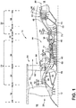
- Figure 1 is a schematic cross-sectional diagram of a turbine engine 10 for an aircraft.
- the engine 10 has a generally longitudinally extending axis or centerline 12 extending forward 14 to aft 16.
- the engine 10 includes, in downstream serial flow relationship, a fan section 18 including a fan 20, a compressor section 22 including a booster or low pressure (LP) compressor 24 and a high pressure (HP) compressor 26, a combustion section 28 including a combustor 30, a turbine section 32 including a HP turbine 34, and a LP turbine 36, and an exhaust section 38.
- LP booster or low pressure
- HP high pressure
- the fan section 18 includes a fan casing 40 surrounding the fan 20.
- the fan 20 includes a plurality of fan blades 42 disposed radially about the centerline 12.
- the HP compressor 26, the combustor 30, and the HP turbine 34 form a core 44 of the engine 10, which generates combustion gases.
- the core 44 is surrounded by core casing 46, which can be coupled with the fan casing 40.
- a LP shaft or spool 50 which is disposed coaxially about the centerline 12 of the engine 10 within the larger diameter annular HP spool 48, drivingly connects the LP turbine 36 to the LP compressor 24 and fan 20.
- the LP compressor 24 and the HP compressor 26 respectively include a plurality of compressor stages 52, 54, in which a set of compressor blades 56, 58 rotate relative to a corresponding set of static compressor vanes 60, 62 (also called a nozzle) to compress or pressurize the stream of fluid passing through the stage.
- a single compressor stage 52, 54 multiple compressor blades 56, 58 can be provided in a ring and can extend radially outwardly relative to the centerline 12, from a blade platform to a blade tip, while the corresponding static compressor vanes 60, 62 are positioned upstream of and adjacent to the rotating blades 56, 58. It is noted that the number of blades, vanes, and compressor stages shown in Figure 1 were selected for illustrative purposes only, and that other numbers are possible.
- the blades 56, 58 for a stage of the compressor can be mounted to a disk 59, which is mounted to the corresponding one of the HP and LP spools 48, 50, with each stage having its own disk 59, 61.
- the vanes 60, 62 for a stage of the compressor can be mounted to the core casing 46 in a circumferential arrangement.
- the HP turbine 34 and the LP turbine 36 respectively include a plurality of turbine stages 64, 66, in which a set of turbine blades 68, 70 are rotated relative to a corresponding set of static turbine vanes 72, 74 (also called a nozzle) to extract energy from the stream of fluid passing through the stage.
- multiple turbine vanes 72, 74 can be provided in a ring and can extend radially outwardly relative to the centerline 12, while the corresponding rotating blades 68, 70 are positioned downstream of and adjacent to the static turbine vanes 72, 74 and can also extend radially outwardly relative to the centerline 12, from a blade platform to a blade tip. It is noted that the number of blades, vanes, and turbine stages shown in Figure 1 were selected for illustrative purposes only, and that other numbers are possible.
- the blades 68, 70 for a stage of the turbine can be mounted to a disk 71, which is mounted to the corresponding one of the HP and LP spools 48, 50, with each stage having its own disk 71, 73.
- the vanes 72, 74 for a stage of the compressor can be mounted to the core casing 46 in a circumferential arrangement.
- the portions of the engine 10 mounted to and rotating with either or both of the spools 48, 50 are also referred to individually or collectively as a rotor 53.
- the stationary portions of the engine 10 including portions mounted to the core casing 46 are also referred to individually or collectively as a stator 63.
- the airflow exiting the fan section 18 is split such that a portion of the airflow is channeled into the LP compressor 24, which then supplies pressurized ambient air 76 to the HP compressor 26, which further pressurizes the ambient air.
- the pressurized air 76 from the HP compressor 26 is mixed with fuel in the combustor 30 and ignited, thereby generating combustion gases. Some work is extracted from these gases by the HP turbine 34, which drives the HP compressor 26.
- the combustion gases are discharged into the LP turbine 36, which extracts additional work to drive the LP compressor 24, and the exhaust gas is ultimately discharged from the engine 10 via the exhaust section 38.
- the driving of the LP turbine 36 drives the LP spool 50 to rotate the fan 20 and the LP compressor 24.
- a remaining portion of the airflow 78 bypasses the LP compressor 24 and engine core 44 and exits the engine assembly 10 through a stationary vane row, and more particularly an outlet guide vane assembly 80, comprising a plurality of airfoil guide vanes 82, at the fan exhaust side 84. More specifically, a circumferential row of radially extending airfoil guide vanes 82 are utilized adjacent the fan section 18 to exert some directional control of the airflow 78.
- the ambient air supplied by the fan 20 can bypass the engine core 44 and be used for cooling of portions, especially hot portions, of the engine 10, and/or used to cool or power other aspects of the aircraft.
- the hot portions of the engine are normally the combustor 30 and components downstream of the combustor 30, especially the turbine section 32, with the HP turbine 34 being the hottest portion as it is directly downstream of the combustion section 28.
- Other sources of cooling fluid can be, but is not limited to, fluid discharged from the LP compressor 24 or the HP compressor 26. This fluid can be bleed air 77 which can include air drawn from the LP or HP compressors 24, 26 that bypasses the combustor 30 as cooling sources for the turbine section 32. This is a common engine configuration, not meant to be limiting.
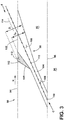
- FIG 2 is a side section view of the combustor 30 and HP turbine 34 of the engine 10 from Figure 1 .
- the combustor 30 includes a deflector 75 and a combustor liner 79.
- Adjacent to the turbine blade 68 of the turbine 34 in the axial direction are sets of radially-spaced, static turbine vanes 72, with adjacent vanes 72 forming nozzles therebetween. The nozzles turn combustion gas to better flow into the rotating blades so that the maximum energy may be extracted by the turbine 34.
- a cooling fluid flow C passes through the vanes 72 to cool the vanes 72 as a hot combustion gas flow H passes along the exterior of the vanes 72.
- a shroud assembly 81 is adjacent to the rotating blade 68 to minimize flow loss in the turbine 34. Similar shroud assemblies can also be associated with the LP turbine 36, the LP compressor 24, or the HP compressor 26.
- One or more of the engine components of the engine 10 includes a film-cooled substrate in which a film cooling hole, or film hole, of an embodiment disclosed further herein may be provided.
- a film cooling hole, or film hole of an embodiment disclosed further herein may be provided.
- the engine component having a film-cooled substrate can include the blades 68, 70, vanes or nozzles 72, 74, combustor deflector 75, combustor liner 79, or shroud assembly 81, described in Figures 1-2 .
- Other non-limiting examples where film cooling is used include turbine transition ducts and exhaust nozzles.
- FIG 3 is a schematic, sectional view of a hole 88, illustrated as a film hole, located in the turbine engine 10.
- the hole 88 is located in an engine component 90, such as a leading edge for an airfoil, comprising a substrate 92 separating a hot combustion gas flow H from a cooling fluid flow C.
- the cooling air can be ambient air supplied by the fan 20 which bypasses the engine core 44, air from the LP compressor 24, or air from the HP compressor 26.
- the engine component 90 includes a substrate 92 having a hot surface 94 facing the hot combustion gas flow H and a cool surface 96 facing the cooling fluid C.
- the substrate 92 may form a wall of the engine component 90 that can be an exterior or interior wall of the engine component 90.
- the first engine component 90 can define at least one interior cavity 98 comprising the cool surface 96.
- the hot surface 94 may be an exterior surface of the engine component 90. In the case of a turbine engine, the hot surface 94 may be exposed to gases having temperatures in the range of 1000 °C to 2000 °C.
- Suitable materials for the substrate 92 include, but are not limited to, steel, refractory metals such as titanium, or superalloys based on nickel, cobalt, or iron, and ceramic matrix composites.
- the superalloys can include those in equi-axed, directionally solidified, and single crystal structures.
- the engine component 90 further includes one or more film hole(s) 88 extending through the substrate 92 that provide fluid communication between the interior cavity 98 and the hot surface 94 of the engine component 90.
- the cooling fluid flow C is supplied to the interior cavity 98 and out of the hole 88 to create a thin layer or film of cool air on the hot surface 94, protecting it from the hot combustion gas flow H. While only one hole 88 is shown in Figure 3 , it is understood that the engine component 90 may be provided with multiple film holes 88, which be arranged in any desired configuration on the engine component 90.
- the substrate 92 is shown as being generally planar, it is understood that that the substrate 92 may be curved for many engine components. However, the curvature of the substrate 92 may be slight in comparison to the size of the hole 88, and so for the purposes of discussion and illustration, the substrate 92 is shown as planar. Whether the substrate 92 is planar or curved local to the hole 88, the hot and cool surfaces 94, 96 may be parallel to each other as shown herein, or may lie in non-parallel planes.
- the hole 88 can have an inlet 100 provided on the cool surface 96 of the substrate 92, an outlet region comprising an outlet 102 provided on the hot surface 94, and a film hole passage 104 connecting the inlet 100 and the outlet 102.
- the film hole passage 104 can include a metering section 106 having a circular cross section for metering of the mass flow rate of the cooling fluid flow C, and a diffusing section 108 in which the cooling fluid C is expanded to form a lower momentum cooling film on the hot surface 94.
- the diffusing section 108 is downstream of the metering section 106 with respect to the direction of cooling fluid flow C through the film hole passage 104.
- the diffusing section 108 may be in serial flow communication with the metering section 106.
- the metering section 106 can be provided at or near the inlet 100, while the diffusing section 108 can be defined at or near the outlet 102. In most implementations, the diffusing section 108 defines the outlet 102.
- the cooling fluid flow C through the film hole passage 104 is along the longitudinal axis of the film hole passage 104, also referred to herein as the centerline 110, which passes through the geometric center of the cross-sectional area of the metering section 106.
- the hole 88 can be inclined in a downstream direction of cooling fluid flow C through the film hole passage 104 such that the centerline 110 is non-orthogonal to the hot and cool surfaces 94, 96.
- the hole 88 may have a centerline 110 that is orthogonal to one or both of the hot and cool surfaces 94, 96 in the localized area of the substrate 92 through which the centerline 110 passes.
- the centerline 110 of the hole 88 may not be oriented in the direction of the hot combustion gas flow H, such that the vector of the cooling fluid flow C differs from that of the hot combustion gas flow H.
- a film hole that has a compound angle defines a cooling flow vector that differs from the hot combustion gas flow vector not only in cross sectional view, but also in the top-down view looking at the hot surface 94.
- the diffusing section 108 can comprise a conical section 109.
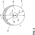
- a layup portion 112 extends along the conical section 109 closest to the hot surface 94 and is defined by an inner dimension D I having a centerline 114 offset from the centerline 110. In this way, when viewed from the outlet 102, the inner dimension D I encompasses an area 113 asymmetrical to the centerline 110. While illustrated closest to the hot surface 94, the layup portion 112 can be at any orientation relative to the hot surface, for example but not limited to the opposite side or encompassing the entire conical section 109.
- a predetermined inner dimension D P and the layup portion 112 together collectively define the asymmetrical area 113.
- the predetermined inner dimension D P is symmetrical around the centerline 110 to form, for example, a circle 115.
- the layup portion 112 can be provided on a portion of the hole so as to form a crescent portion 116 adjacent the circle. While a circle is shown as an example cross-sectional profile, it will be understood by those skilled in the art that other cross-sectional profiles can be employed without departing from the scope of this invention.
- the size of the hole 88 can be generalized as having a dimension, and the expression of that dimension as a diameter herein shall not be construed as limiting the scope of this invention.
- the hole can have a circular or non-circular cross-section.
- the dimension is the inner diameter of the circle.
- the dimension may be characterized as an effective diameter or dimension (measured or calculated), which need not be the diameter is a technical sense, even if the dimension is referred to as a diameter.
- the dimension can be the major/minor axis or some other effective dimension, any of which can be referred to as a diameter.
- the layup portion 112 can vary in depth and extent of arc section comprising the crescent portion 116 depending on factors such as coating thickness, coating application methods, hole size, etc.
- the arc section need not be a circular arc section.
- a method of making the film hole 88 includes forming the hole 88 in the engine component 90 by plunging an electro-discharge tool to form the metering section through the wall thickness, then plunging a second tool or orientation to form the layup portion having the layup portion 112 that provides the hole 88 with the inner dimension D I which is greater than the predetermined inner dimension D P .
- the layup portion 112 forming an area where a coating is applied to the component 90 such that the coating fills in the layup portion leaving the hole with a diameter equivalent to the predetermined inner dimension D P .
- the coating can be applied in one or multiple layers depending on the method of application.
- the coating can be a thermal barrier coating (TBC) which includes the superalloy substrate already described along with a metallic bond coat, thermally grown oxide, and one or more ceramic topcoats.
- TBC thermal barrier coating
- an environmental barrier coating is a multi-layer stack-up of coatings, for example but not limited to an air plasma TBC and mullite.
- Other methods for forming the film hole include but are not limited to machining via electrode, 3-D printing, SLA, machining via a laser, or by casting in.
- thermal barrier coating impact the laydown portion of the conical region which is the region opposite of the layup portion described herein. Placing thermal barrier coating on the layup portion optimizes aerodynamic flow in the film hole by maintaining the laydown portion geometry as intended. Testing done with the final aerodynamic shape using the method described quantified the benefits discussed herein.
Abstract
An apparatus and method relating to a film hole 88 of a component 90 of a turbine engine 10 comprising including forming the hole 88 in the component 90 and applying a coating to the component 90 such that the coating fills in portions 113 of the film hole 88.
Description
- Turbine engines, and particularly gas or combustion turbine engines, are rotary engines that extract energy from a flow of combusted gases passing through the engine onto a multitude of rotating turbine blades.
- Engine efficiency increases with temperature of combustion gases. However, the combustion gases heat the various components along their flow path, which in turn requires cooling thereof to achieve a long engine lifetime. Typically, the hot gas path components are cooled by bleeding air from the compressor. This cooling process reduces engine efficiency, as the bled air is not used in the combustion process.
- Turbine engine cooling art is mature and includes numerous patents for various aspects of cooling circuits and features in the various hot gas path components. For example, the combustor includes radially outer and inner liners, which require cooling during operation. Turbine nozzles include hollow vanes supported between outer and inner bands, which also require cooling. Turbine rotor blades are hollow and typically include cooling circuits therein, with the blades being surrounded by turbine shrouds, which also require cooling. The hot combustion gases are discharged through an exhaust which may also be lined, and suitably cooled.
- In all of these exemplary turbine engine components, thin metal walls of high strength superalloy metals are typically used for enhanced durability while minimizing the need for cooling thereof. Various cooling circuits and features are tailored for these individual components in their corresponding environments in the engine. In addition, all of these components typically include common rows of film cooling holes.
- A typical film cooling hole is a cylindrical bore inclined at a shallow angle through the heated wall for discharging a film of cooling air along the external surface of the wall to provide thermal insulation against the flow from hot combustion gases during operation. The film is discharged at a shallow angle over the wall outer surface to minimize the likelihood of undesirable blow-off, which would lead to flow separation and a loss of the film cooling effectiveness.
- A coating, such as a thermal barrier coating can be placed on portions of the film cooling hole to prevent thermal damage due to high temperatures.
- In one aspect, there is provided a method of making a film hole of a predetermined inner dimension in a component of a turbine engine comprising: forming a hole in the component with the hole having an layup portion providing the hole with an inner dimension greater than the predetermined inner dimension, applying a coating to the component such that the coating fills in the layup portion leaving the hole with a dimension equivalent to the predetermined inner dimension.
- In another aspect, there is provided an engine component for a turbine engine, which generates a hot combustion gas flow, and provides a cooling fluid flow, comprising: a wall separating the hot combustion gas flow from the cooling fluid flow and having a hot surface along with the hot combustion gas flows in a hot flow path and a cooled surface facing the cooling fluid flow, and at least one film hole comprising a predetermined inner dimension portion and a layup portion adjacent the predetermined inner dimension portion, and a coating filling the layup portion.
- In the drawings:
-
Figure 1 is a schematic cross-sectional diagram of a turbine engine for an aircraft. -
Figure 2 is a side section view of a combustor and a high pressure turbine of the engine fromFigure 1 . -
Figure 3 is a sectional view through a film hole of an engine component of the engine fromFigure 1 . -
Figure 4 is top view of the outlet of the film hole ofFigure 3 . - The described embodiments of the present invention are directed to the formation of a hole such as a film hole in an engine component such as an airfoil. For purposes of illustration, the present invention will be described with respect to the turbine for an aircraft turbine engine. It will be understood, however, that the invention is not so limited and may have general applicability within an engine, including compressors, as well as in non-aircraft applications, such as other mobile applications and non-mobile industrial, commercial, and residential applications.
- Additionally, as used herein, the terms "radial" or "radially" refer to a dimension extending between a center longitudinal axis of the engine and an outer engine circumference.
- All directional references (e.g., radial, axial, proximal, distal, upper, lower, upward, downward, left, right, lateral, front, back, top, bottom, above, below, vertical, horizontal, clockwise, counterclockwise, upstream, downstream, aft, etc.) are only used for identification purposes to aid the reader's understanding of the present invention, and do not create limitations, particularly as to the position, orientation, or use of the invention. Connection references (e.g., attached, coupled, connected, and joined) are to be construed broadly and can include intermediate members between a collection of elements and relative movement between elements unless otherwise indicated. As such, connection references do not necessarily infer that two elements are directly connected and in fixed relation to one another. The exemplary drawings are for purposes of illustration only and the dimensions, positions, order and relative sizes reflected in the drawings attached hereto can vary.
-
Figure 1 is a schematic cross-sectional diagram of aturbine engine 10 for an aircraft. Theengine 10 has a generally longitudinally extending axis orcenterline 12 extending forward 14 toaft 16. Theengine 10 includes, in downstream serial flow relationship, afan section 18 including afan 20, acompressor section 22 including a booster or low pressure (LP)compressor 24 and a high pressure (HP)compressor 26, acombustion section 28 including acombustor 30, aturbine section 32 including a HPturbine 34, and aLP turbine 36, and anexhaust section 38. - The
fan section 18 includes a fan casing 40 surrounding thefan 20. Thefan 20 includes a plurality offan blades 42 disposed radially about thecenterline 12. The HPcompressor 26, thecombustor 30, and the HPturbine 34 form acore 44 of theengine 10, which generates combustion gases. Thecore 44 is surrounded bycore casing 46, which can be coupled with the fan casing 40. - A HP shaft or
spool 48 disposed coaxially about thecenterline 12 of theengine 10 drivingly connects the HPturbine 34 to the HPcompressor 26. A LP shaft orspool 50, which is disposed coaxially about thecenterline 12 of theengine 10 within the larger diameter annular HPspool 48, drivingly connects theLP turbine 36 to theLP compressor 24 andfan 20. - The
LP compressor 24 and the HPcompressor 26 respectively include a plurality ofcompressor stages compressor blades static compressor vanes 60, 62 (also called a nozzle) to compress or pressurize the stream of fluid passing through the stage. In asingle compressor stage multiple compressor blades centerline 12, from a blade platform to a blade tip, while the corresponding static compressor vanes 60, 62 are positioned upstream of and adjacent to therotating blades Figure 1 were selected for illustrative purposes only, and that other numbers are possible. - The
blades disk 59, which is mounted to the corresponding one of the HP andLP spools own disk vanes core casing 46 in a circumferential arrangement. - The HP
turbine 34 and theLP turbine 36 respectively include a plurality ofturbine stages turbine blades static turbine vanes 72, 74 (also called a nozzle) to extract energy from the stream of fluid passing through the stage. In asingle turbine stage multiple turbine vanes centerline 12, while the correspondingrotating blades static turbine vanes centerline 12, from a blade platform to a blade tip. It is noted that the number of blades, vanes, and turbine stages shown inFigure 1 were selected for illustrative purposes only, and that other numbers are possible. - The
blades disk 71, which is mounted to the corresponding one of the HP andLP spools own disk vanes core casing 46 in a circumferential arrangement. - The portions of the
engine 10 mounted to and rotating with either or both of thespools rotor 53. The stationary portions of theengine 10 including portions mounted to thecore casing 46 are also referred to individually or collectively as astator 63. - In operation, the airflow exiting the
fan section 18 is split such that a portion of the airflow is channeled into theLP compressor 24, which then supplies pressurizedambient air 76 to the HPcompressor 26, which further pressurizes the ambient air. The pressurizedair 76 from the HPcompressor 26 is mixed with fuel in thecombustor 30 and ignited, thereby generating combustion gases. Some work is extracted from these gases by the HPturbine 34, which drives the HPcompressor 26. The combustion gases are discharged into theLP turbine 36, which extracts additional work to drive theLP compressor 24, and the exhaust gas is ultimately discharged from theengine 10 via theexhaust section 38. The driving of theLP turbine 36 drives theLP spool 50 to rotate thefan 20 and theLP compressor 24. - A remaining portion of the
airflow 78 bypasses theLP compressor 24 andengine core 44 and exits theengine assembly 10 through a stationary vane row, and more particularly an outletguide vane assembly 80, comprising a plurality ofairfoil guide vanes 82, at thefan exhaust side 84. More specifically, a circumferential row of radially extendingairfoil guide vanes 82 are utilized adjacent thefan section 18 to exert some directional control of theairflow 78. - Some of the ambient air supplied by the
fan 20 can bypass theengine core 44 and be used for cooling of portions, especially hot portions, of theengine 10, and/or used to cool or power other aspects of the aircraft. In the context of a turbine engine, the hot portions of the engine are normally thecombustor 30 and components downstream of thecombustor 30, especially theturbine section 32, with the HPturbine 34 being the hottest portion as it is directly downstream of thecombustion section 28. Other sources of cooling fluid can be, but is not limited to, fluid discharged from theLP compressor 24 or theHP compressor 26. This fluid can be bleedair 77 which can include air drawn from the LP orHP compressors combustor 30 as cooling sources for theturbine section 32. This is a common engine configuration, not meant to be limiting. -
Figure 2 is a side section view of thecombustor 30 andHP turbine 34 of theengine 10 fromFigure 1 . Thecombustor 30 includes adeflector 75 and acombustor liner 79. Adjacent to theturbine blade 68 of theturbine 34 in the axial direction are sets of radially-spaced,static turbine vanes 72, withadjacent vanes 72 forming nozzles therebetween. The nozzles turn combustion gas to better flow into the rotating blades so that the maximum energy may be extracted by theturbine 34. A cooling fluid flow C passes through thevanes 72 to cool thevanes 72 as a hot combustion gas flow H passes along the exterior of thevanes 72. Ashroud assembly 81 is adjacent to therotating blade 68 to minimize flow loss in theturbine 34. Similar shroud assemblies can also be associated with theLP turbine 36, theLP compressor 24, or theHP compressor 26. - One or more of the engine components of the
engine 10 includes a film-cooled substrate in which a film cooling hole, or film hole, of an embodiment disclosed further herein may be provided. Some non-limiting examples of the engine component having a film-cooled substrate can include theblades nozzles combustor deflector 75,combustor liner 79, orshroud assembly 81, described inFigures 1-2 . Other non-limiting examples where film cooling is used include turbine transition ducts and exhaust nozzles. -
Figure 3 is a schematic, sectional view of ahole 88, illustrated as a film hole, located in theturbine engine 10. In an exemplary embodiment thehole 88 is located in anengine component 90, such as a leading edge for an airfoil, comprising asubstrate 92 separating a hot combustion gas flow H from a cooling fluid flow C. As discussed above with respect toFigures 1 and2 , in the context of a turbine engine, the cooling air can be ambient air supplied by thefan 20 which bypasses theengine core 44, air from theLP compressor 24, or air from theHP compressor 26. - The
engine component 90 includes asubstrate 92 having ahot surface 94 facing the hot combustion gas flow H and acool surface 96 facing the cooling fluid C. Thesubstrate 92 may form a wall of theengine component 90 that can be an exterior or interior wall of theengine component 90. Thefirst engine component 90 can define at least one interior cavity 98 comprising thecool surface 96. Thehot surface 94 may be an exterior surface of theengine component 90. In the case of a turbine engine, thehot surface 94 may be exposed to gases having temperatures in the range of 1000 °C to 2000 °C. Suitable materials for thesubstrate 92 include, but are not limited to, steel, refractory metals such as titanium, or superalloys based on nickel, cobalt, or iron, and ceramic matrix composites. The superalloys can include those in equi-axed, directionally solidified, and single crystal structures. - The
engine component 90 further includes one or more film hole(s) 88 extending through thesubstrate 92 that provide fluid communication between the interior cavity 98 and thehot surface 94 of theengine component 90. During operation, the cooling fluid flow C is supplied to the interior cavity 98 and out of thehole 88 to create a thin layer or film of cool air on thehot surface 94, protecting it from the hot combustion gas flow H. While only onehole 88 is shown inFigure 3 , it is understood that theengine component 90 may be provided with multiple film holes 88, which be arranged in any desired configuration on theengine component 90. - It is noted that, in any of the embodiments discussed herein, although the
substrate 92 is shown as being generally planar, it is understood that that thesubstrate 92 may be curved for many engine components. However, the curvature of thesubstrate 92 may be slight in comparison to the size of thehole 88, and so for the purposes of discussion and illustration, thesubstrate 92 is shown as planar. Whether thesubstrate 92 is planar or curved local to thehole 88, the hot andcool surfaces - The
hole 88 can have aninlet 100 provided on thecool surface 96 of thesubstrate 92, an outlet region comprising anoutlet 102 provided on thehot surface 94, and afilm hole passage 104 connecting theinlet 100 and theoutlet 102. Thefilm hole passage 104 can include ametering section 106 having a circular cross section for metering of the mass flow rate of the cooling fluid flow C, and adiffusing section 108 in which the cooling fluid C is expanded to form a lower momentum cooling film on thehot surface 94. [Do not wish to commit to "wider" here. And "slower" is contained in the use of lower momentum.] - The diffusing
section 108 is downstream of themetering section 106 with respect to the direction of cooling fluid flow C through thefilm hole passage 104. The diffusingsection 108 may be in serial flow communication with themetering section 106. Themetering section 106 can be provided at or near theinlet 100, while the diffusingsection 108 can be defined at or near theoutlet 102. In most implementations, the diffusingsection 108 defines theoutlet 102. - The cooling fluid flow C through the
film hole passage 104 is along the longitudinal axis of thefilm hole passage 104, also referred to herein as thecenterline 110, which passes through the geometric center of the cross-sectional area of themetering section 106. Thehole 88 can be inclined in a downstream direction of cooling fluid flow C through thefilm hole passage 104 such that thecenterline 110 is non-orthogonal to the hot andcool surfaces hole 88 may have acenterline 110 that is orthogonal to one or both of the hot andcool surfaces substrate 92 through which thecenterline 110 passes. In other embodiments, thecenterline 110 of thehole 88 may not be oriented in the direction of the hot combustion gas flow H, such that the vector of the cooling fluid flow C differs from that of the hot combustion gas flow H. For example, a film hole that has a compound angle defines a cooling flow vector that differs from the hot combustion gas flow vector not only in cross sectional view, but also in the top-down view looking at thehot surface 94. - The diffusing
section 108 can comprise aconical section 109. Alayup portion 112 extends along theconical section 109 closest to thehot surface 94 and is defined by an inner dimension DI having acenterline 114 offset from thecenterline 110. In this way, when viewed from theoutlet 102, the inner dimension DI encompasses anarea 113 asymmetrical to thecenterline 110. While illustrated closest to thehot surface 94, thelayup portion 112 can be at any orientation relative to the hot surface, for example but not limited to the opposite side or encompassing the entireconical section 109. - As is illustrated in
Figure 4 a predetermined inner dimension DP and thelayup portion 112 together collectively define theasymmetrical area 113. The predetermined inner dimension DP is symmetrical around thecenterline 110 to form, for example, acircle 115. Thelayup portion 112 can be provided on a portion of the hole so as to form acrescent portion 116 adjacent the circle. While a circle is shown as an example cross-sectional profile, it will be understood by those skilled in the art that other cross-sectional profiles can be employed without departing from the scope of this invention. - In addition, while the measurement of various portions of the
hole 88 is described in terms of a dimension, the size of thehole 88, and various portions thereof, can be generalized as having a dimension, and the expression of that dimension as a diameter herein shall not be construed as limiting the scope of this invention. The hole can have a circular or non-circular cross-section. In the case of a circular cross section, the dimension is the inner diameter of the circle. However, for non-circular cross sections, the dimension may be characterized as an effective diameter or dimension (measured or calculated), which need not be the diameter is a technical sense, even if the dimension is referred to as a diameter. For example, in the case of an elliptical cross section, the dimension can be the major/minor axis or some other effective dimension, any of which can be referred to as a diameter. Thelayup portion 112 can vary in depth and extent of arc section comprising thecrescent portion 116 depending on factors such as coating thickness, coating application methods, hole size, etc. Likewise, the arc section need not be a circular arc section. - A method of making the
film hole 88 includes forming thehole 88 in theengine component 90 by plunging an electro-discharge tool to form the metering section through the wall thickness, then plunging a second tool or orientation to form the layup portion having thelayup portion 112 that provides thehole 88 with the inner dimension DI which is greater than the predetermined inner dimension DP. Thelayup portion 112 forming an area where a coating is applied to thecomponent 90 such that the coating fills in the layup portion leaving the hole with a diameter equivalent to the predetermined inner dimension DP. The coating can be applied in one or multiple layers depending on the method of application. The coating can be a thermal barrier coating (TBC) which includes the superalloy substrate already described along with a metallic bond coat, thermally grown oxide, and one or more ceramic topcoats. - In the case of a CMC substrate, an environmental barrier coating (EBC) is a multi-layer stack-up of coatings, for example but not limited to an air plasma TBC and mullite. Other methods for forming the film hole include but are not limited to machining via electrode, 3-D printing, SLA, machining via a laser, or by casting in.
- Current methods for applying a thermal barrier coating impact the laydown portion of the conical region which is the region opposite of the layup portion described herein. Placing thermal barrier coating on the layup portion optimizes aerodynamic flow in the film hole by maintaining the laydown portion geometry as intended. Testing done with the final aerodynamic shape using the method described quantified the benefits discussed herein.
- It should be appreciated that application of the disclosed design is not limited to turbine engines with fan and booster sections, but is applicable to turbojets and turbo engines as well.
- This written description uses examples to disclose the invention, including the best mode, and also to enable any person skilled in the art to practice the invention, including making and using any devices or systems and performing any incorporated methods. The patentable scope of the invention is defined by the claims, and may include other examples that occur to those skilled in the art. Such other examples are intended to be within the scope of the claims if they have structural elements that do not differ from the literal language of the claims, or if they include equivalent structural elements with insubstantial differences from the literal languages of the claims.
- Various aspects and embodiments of the present invention are defined by the following numbered clauses:
- 1. A method of making a film hole of a predetermined inner dimension in a component of a turbine engine comprising:
- forming a hole in the component with the hole having a layup portion providing the hole with an inner dimension greater than the predetermined inner dimension;
- applying a coating to the component such that the coating fills in the layup portion leaving the hole with a dimension equivalent to the predetermined inner dimension.
- 2. The method of clause 1, wherein the layup portion is provided on a portion of the hole.
- 3. The method of any preceding clause, wherein the predetermined inner dimension defines a circle.
- 4. The method of any preceding clause, wherein the layup portion comprises a crescent portion adjacent the circle.
- 5. The method of any preceding clause, wherein the layup portion comprises a circle having a larger diameter than the predetermined inner dimension.
- 6. The method of any preceding clause, wherein the hole comprises a conical section and the layup portion extends along the conical section.
- 7. The method of any preceding clause, wherein the hole comprises a metering section upstream of the conical section.
- 8. The method of any preceding clause, wherein the metering section comprises a circular cross section.
- 9. The method of any preceding clause, wherein the coating comprises a substrate, bond coat, and one or more ceramic-based topcoats.
- 10. The method of any preceding clause, wherein the film hole is made by machining via electro-discharge machining, 3-D printing, machining via a laser, or by casting in.
- 11. The method of any preceding clause, wherein the inner dimension is at least one of a diameter, major axis or minor axis.
- 12. The method of any preceding clause, wherein the hole has at least one of a circular or non-circular cross section.
- 13. An engine component for a turbine engine, which generates a hot combustion gas flow, and provides a cooling fluid flow, comprising:
- a wall separating the hot combustion gas flow from the cooling fluid flow and having a hot surface along with the hot combustion gas flows in a hot flow path and a cooled surface facing the cooling fluid flow; and
- at least one film hole comprising a predetermined inner dimension portion and a layup portion adjacent the predetermined inner dimension portion; and
- a coating filling the layup portion.
- 14. The engine component of any preceding clause, wherein the layup portion is provided on only a portion of the predetermined inner dimension portion.
- 15. The engine component of any preceding clause, wherein the predetermined inner dimension portion is symmetrical about its centerline.
- 16. The engine component of any preceding clause, wherein the predetermined inner dimension portion is a circle.
- 17. The engine component of any preceding clause, wherein the layup portion and predetermined inner dimension portion collectively define an area asymmetrical to the centerline of the predetermined inner dimension portion.
- 18. The engine component of any preceding clause, wherein the predetermined inner dimension portion is a circle.
- 19. The engine component of any preceding clause, wherein the layup portion is a crescent.
- 20. The engine component of any preceding clause, wherein the layup portion comprises a circle having a larger diameter than the predetermined inner dimension.
- 21. The engine component of any preceding clause, wherein the film hole comprises a conical section and the layup portion extends along the conical section.
- 22. The engine component of any preceding clause, wherein the film hole comprises a metering section upstream of the conical section.
- 23. The engine component of any preceding clause, wherein the metering section comprises a circular cross section.
- 24. The engine component of any preceding clause, wherein the coating comprises multiple layers.
Claims (15)
- An engine (10) component (90) for a turbine engine (10), which generates a hot combustion gas flow (H), and provides a cooling fluid flow (C), comprising:a wall separating the hot combustion gas flow (H) from the cooling fluid flow (C) and having a hot surface (94) along which the hot combustion gas flows (H) in a hot flow path and a cooled surface (96) facing the cooling fluid flow (C); andat least one film hole (88) comprising a predetermined inner dimension portion (DP) and a layup portion (112) adjacent the predetermined inner dimension portion (DP); anda coating filling the layup portion (112).
- The engine (10) component (90) of claim 1, wherein the layup portion (112) is provided on only a portion (113) of the predetermined inner dimension portion (DP).
- The engine (10) component (90) of either of claim 1 or 2, wherein the predetermined inner dimension portion (DP) is symmetrical about its centerline (110).
- The engine (10) component (90) of claim 3, wherein the layup portion (112) and predetermined inner dimension portion (DP) collectively define an area asymmetrical to the centerline (110) of the predetermined inner dimension portion (DP).
- The engine (10) component (90) of any preceding claim, wherein the predetermined inner dimension portion (DP) is a circle (115).
- The engine (10) component (90) of claim 5, wherein the layup portion (112) is a crescent (116).
- The engine (10) component (90) of any preceding claim, wherein the layup portion (112) comprises a circle having a larger diameter (DI) than the predetermined inner dimension (DP).
- The engine (10) component (90) of any preceding claim, wherein the film hole (88) comprises a conical section (109) and the layup portion (112) extends along the conical section (109).
- The engine (10) component (90) of claim 8, wherein the film hole (88) comprises a metering section (106) upstream of the conical section (109).
- The engine (10) component (90) of any preceding claim, wherein the coating comprises multiple layers.
- A method of making a film hole (88) of a predetermined inner dimension in a component (90) of a turbine engine (10) comprising:forming a hole (88) in the component with the hole having a layup portion (112) providing the hole with an inner dimension greater than the predetermined inner dimension;applying a coating to the component such that the coating fills in the layup portion leaving the hole with a dimension equivalent to the predetermined inner dimension.
- The method of claim 11, wherein the layup portion (112) is provided on a portion of the hole (88).
- The method of either of claim 11 or 12, wherein the predetermined inner dimension defines a circle.
- The method of claim 13, wherein the layup portion (112) comprises a crescent portion adjacent the circle.
- The method of claim 13, wherein the layup portion (112) comprises a circle having a larger diameter than the predetermined inner dimension.
Applications Claiming Priority (1)
| Application Number | Priority Date | Filing Date | Title |
|---|---|---|---|
| US15/073,687 US10443395B2 (en) | 2016-03-18 | 2016-03-18 | Component for a turbine engine with a film hole |
Publications (1)
| Publication Number | Publication Date |
|---|---|
| EP3219920A1 true EP3219920A1 (en) | 2017-09-20 |
Family
ID=58347233
Family Applications (1)
| Application Number | Title | Priority Date | Filing Date |
|---|---|---|---|
| EP17161186.6A Withdrawn EP3219920A1 (en) | 2016-03-18 | 2017-03-15 | Component for a turbine engine with a film hole |
Country Status (5)
| Country | Link |
|---|---|
| US (2) | US10443395B2 (en) |
| EP (1) | EP3219920A1 (en) |
| JP (1) | JP2017172583A (en) |
| CN (1) | CN107201920A (en) |
| CA (1) | CA2960359A1 (en) |
Cited By (1)
| Publication number | Priority date | Publication date | Assignee | Title |
|---|---|---|---|---|
| CN112983561A (en) * | 2021-05-11 | 2021-06-18 | 中国航发四川燃气涡轮研究院 | Quincunx gas film hole and forming method, turbine blade and forming method and gas engine |
Families Citing this family (3)
| Publication number | Priority date | Publication date | Assignee | Title |
|---|---|---|---|---|
| US11359494B2 (en) * | 2019-08-06 | 2022-06-14 | General Electric Company | Engine component with cooling hole |
| US20230243265A1 (en) * | 2022-01-28 | 2023-08-03 | Raytheon Technologies Corporation | Ceramic matrix composite article and method of making the same |
| CN114893255B (en) * | 2022-05-12 | 2023-05-05 | 中国航发四川燃气涡轮研究院 | Crescent air film hole structure, forming method, turbine blade and processing method thereof |
Citations (3)
| Publication number | Priority date | Publication date | Assignee | Title |
|---|---|---|---|---|
| CA2282010A1 (en) * | 1998-09-10 | 2000-03-10 | Abb Research Ltd. | Film-cooling hole and method of producing it |
| US20140161585A1 (en) * | 2012-12-10 | 2014-06-12 | General Electric Company | Turbo-machine component and method |
| EP2937513A2 (en) * | 2014-04-25 | 2015-10-28 | United Technologies Corporation | Method of forming a component and corresponding component |
Family Cites Families (17)
| Publication number | Priority date | Publication date | Assignee | Title |
|---|---|---|---|---|
| US4819325A (en) * | 1987-06-01 | 1989-04-11 | Technical Manufacturing Systems, Inc. | Method of forming electro-discharge machining electrode |
| GB2227965B (en) | 1988-10-12 | 1993-02-10 | Rolls Royce Plc | Apparatus for drilling a shaped hole in a workpiece |
| US6744010B1 (en) | 1991-08-22 | 2004-06-01 | United Technologies Corporation | Laser drilled holes for film cooling |
| US5771577A (en) * | 1996-05-17 | 1998-06-30 | General Electric Company | Method for making a fluid cooled article with protective coating |
| US6042879A (en) | 1997-07-02 | 2000-03-28 | United Technologies Corporation | Method for preparing an apertured article to be recoated |
| US6050777A (en) | 1997-12-17 | 2000-04-18 | United Technologies Corporation | Apparatus and method for cooling an airfoil for a gas turbine engine |
| EP1275747B1 (en) | 2001-07-11 | 2011-02-23 | Alstom Technology Ltd | Method for coating a high temperature resistant article with a thermal protection covering and high temperature resistant article |
| DE10143153A1 (en) | 2001-09-03 | 2003-03-20 | Rolls Royce Deutschland | Turbine blade for a gas turbine with at least one cooling recess |
| US6663919B2 (en) | 2002-03-01 | 2003-12-16 | General Electric Company | Process of removing a coating deposit from a through-hole in a component and component processed thereby |
| US6881439B2 (en) | 2002-12-04 | 2005-04-19 | General Electric Company | Aluminide coating process |
| US20050220618A1 (en) | 2004-03-31 | 2005-10-06 | General Electric Company | Counter-bored film-cooling holes and related method |
| US7216485B2 (en) | 2004-09-03 | 2007-05-15 | General Electric Company | Adjusting airflow in turbine component by depositing overlay metallic coating |
| US8257809B2 (en) | 2007-03-08 | 2012-09-04 | Siemens Energy, Inc. | CMC wall structure with integral cooling channels |
| EP2213759A1 (en) | 2009-01-08 | 2010-08-04 | Siemens Aktiengesellschaft | Method for coating a component with film cooling holes and component |
| US8672613B2 (en) | 2010-08-31 | 2014-03-18 | General Electric Company | Components with conformal curved film holes and methods of manufacture |
| CH706107A1 (en) * | 2012-02-17 | 2013-08-30 | Alstom Technology Ltd | Component of a thermal machine, in particular a gas turbine. |
| US10472972B2 (en) * | 2015-12-01 | 2019-11-12 | General Electric Company | Thermal management of CMC articles having film holes |
-
2016
- 2016-03-18 US US15/073,687 patent/US10443395B2/en active Active
-
2017
- 2017-03-09 JP JP2017044487A patent/JP2017172583A/en active Pending
- 2017-03-09 CA CA2960359A patent/CA2960359A1/en not_active Abandoned
- 2017-03-15 EP EP17161186.6A patent/EP3219920A1/en not_active Withdrawn
- 2017-03-17 CN CN201710160127.3A patent/CN107201920A/en active Pending
-
2019
- 2019-08-19 US US16/544,184 patent/US20200141247A1/en not_active Abandoned
Patent Citations (3)
| Publication number | Priority date | Publication date | Assignee | Title |
|---|---|---|---|---|
| CA2282010A1 (en) * | 1998-09-10 | 2000-03-10 | Abb Research Ltd. | Film-cooling hole and method of producing it |
| US20140161585A1 (en) * | 2012-12-10 | 2014-06-12 | General Electric Company | Turbo-machine component and method |
| EP2937513A2 (en) * | 2014-04-25 | 2015-10-28 | United Technologies Corporation | Method of forming a component and corresponding component |
Cited By (2)
| Publication number | Priority date | Publication date | Assignee | Title |
|---|---|---|---|---|
| CN112983561A (en) * | 2021-05-11 | 2021-06-18 | 中国航发四川燃气涡轮研究院 | Quincunx gas film hole and forming method, turbine blade and forming method and gas engine |
| CN112983561B (en) * | 2021-05-11 | 2021-08-03 | 中国航发四川燃气涡轮研究院 | Quincunx gas film hole and forming method, turbine blade and forming method and gas engine |
Also Published As
| Publication number | Publication date |
|---|---|
| CN107201920A (en) | 2017-09-26 |
| CA2960359A1 (en) | 2017-09-18 |
| US20170268346A1 (en) | 2017-09-21 |
| US10443395B2 (en) | 2019-10-15 |
| JP2017172583A (en) | 2017-09-28 |
| US20200141247A1 (en) | 2020-05-07 |
Similar Documents
| Publication | Publication Date | Title |
|---|---|---|
| US20190085705A1 (en) | Component for a turbine engine with a film-hole | |
| US11448076B2 (en) | Engine component with cooling hole | |
| US20200141247A1 (en) | Component for a turbine engine with a film hole | |
| US11156099B2 (en) | Turbine engine airfoil with a modified leading edge | |
| US11773729B2 (en) | Component for a gas turbine engine with a film hole | |
| EP3061911A1 (en) | Engine component | |
| EP3255248A1 (en) | Engine component for a turbine engine | |
| EP3196414B1 (en) | Dual-fed airfoil tip | |
| US20200024951A1 (en) | Component for a turbine engine with a cooling hole | |
| CN111441829B (en) | Turbine engine component with cooling holes | |
| EP3173586A1 (en) | Engine component with film cooling | |
| EP3211314A1 (en) | Components for a gas turbine engine and corresponding cooling method | |
| US20220145764A1 (en) | Component for a turbine engine with a cooling hole | |
| US10767489B2 (en) | Component for a turbine engine with a hole | |
| US10760431B2 (en) | Component for a turbine engine with a cooling hole | |
| US11391161B2 (en) | Component for a turbine engine with a cooling hole | |
| WO2018034790A1 (en) | Engine component with porous holes | |
| EP2952682A1 (en) | Airfoil for a gas turbine engine with a cooled platform |
Legal Events
| Date | Code | Title | Description |
|---|---|---|---|
| PUAI | Public reference made under article 153(3) epc to a published international application that has entered the european phase |
Free format text: ORIGINAL CODE: 0009012 |
|
| AK | Designated contracting states |
Kind code of ref document: A1 Designated state(s): AL AT BE BG CH CY CZ DE DK EE ES FI FR GB GR HR HU IE IS IT LI LT LU LV MC MK MT NL NO PL PT RO RS SE SI SK SM TR |
|
| AX | Request for extension of the european patent |
Extension state: BA ME |
|
| STAA | Information on the status of an ep patent application or granted ep patent |
Free format text: STATUS: THE APPLICATION IS DEEMED TO BE WITHDRAWN |
|
| 18D | Application deemed to be withdrawn |
Effective date: 20180321 |