EP3061911A1 - Engine component - Google Patents
Engine component Download PDFInfo
- Publication number
- EP3061911A1 EP3061911A1 EP16155996.8A EP16155996A EP3061911A1 EP 3061911 A1 EP3061911 A1 EP 3061911A1 EP 16155996 A EP16155996 A EP 16155996A EP 3061911 A1 EP3061911 A1 EP 3061911A1
- Authority
- EP
- European Patent Office
- Prior art keywords
- centerline
- engine component
- inlet
- outlet
- engine
- Prior art date
- Legal status (The legal status is an assumption and is not a legal conclusion. Google has not performed a legal analysis and makes no representation as to the accuracy of the status listed.)
- Withdrawn
Links
Images


Classifications
-
- F—MECHANICAL ENGINEERING; LIGHTING; HEATING; WEAPONS; BLASTING
- F01—MACHINES OR ENGINES IN GENERAL; ENGINE PLANTS IN GENERAL; STEAM ENGINES
- F01D—NON-POSITIVE DISPLACEMENT MACHINES OR ENGINES, e.g. STEAM TURBINES
- F01D5/00—Blades; Blade-carrying members; Heating, heat-insulating, cooling or antivibration means on the blades or the members
- F01D5/12—Blades
- F01D5/14—Form or construction
- F01D5/18—Hollow blades, i.e. blades with cooling or heating channels or cavities; Heating, heat-insulating or cooling means on blades
- F01D5/186—Film cooling
-
- F—MECHANICAL ENGINEERING; LIGHTING; HEATING; WEAPONS; BLASTING
- F01—MACHINES OR ENGINES IN GENERAL; ENGINE PLANTS IN GENERAL; STEAM ENGINES
- F01D—NON-POSITIVE DISPLACEMENT MACHINES OR ENGINES, e.g. STEAM TURBINES
- F01D11/00—Preventing or minimising internal leakage of working-fluid, e.g. between stages
- F01D11/08—Preventing or minimising internal leakage of working-fluid, e.g. between stages for sealing space between rotor blade tips and stator
-
- F—MECHANICAL ENGINEERING; LIGHTING; HEATING; WEAPONS; BLASTING
- F01—MACHINES OR ENGINES IN GENERAL; ENGINE PLANTS IN GENERAL; STEAM ENGINES
- F01D—NON-POSITIVE DISPLACEMENT MACHINES OR ENGINES, e.g. STEAM TURBINES
- F01D25/00—Component parts, details, or accessories, not provided for in, or of interest apart from, other groups
- F01D25/08—Cooling; Heating; Heat-insulation
- F01D25/12—Cooling
-
- F—MECHANICAL ENGINEERING; LIGHTING; HEATING; WEAPONS; BLASTING
- F01—MACHINES OR ENGINES IN GENERAL; ENGINE PLANTS IN GENERAL; STEAM ENGINES
- F01D—NON-POSITIVE DISPLACEMENT MACHINES OR ENGINES, e.g. STEAM TURBINES
- F01D9/00—Stators
- F01D9/02—Nozzles; Nozzle boxes; Stator blades; Guide conduits, e.g. individual nozzles
- F01D9/023—Transition ducts between combustor cans and first stage of the turbine in gas-turbine engines; their cooling or sealings
-
- F—MECHANICAL ENGINEERING; LIGHTING; HEATING; WEAPONS; BLASTING
- F01—MACHINES OR ENGINES IN GENERAL; ENGINE PLANTS IN GENERAL; STEAM ENGINES
- F01D—NON-POSITIVE DISPLACEMENT MACHINES OR ENGINES, e.g. STEAM TURBINES
- F01D9/00—Stators
- F01D9/02—Nozzles; Nozzle boxes; Stator blades; Guide conduits, e.g. individual nozzles
- F01D9/04—Nozzles; Nozzle boxes; Stator blades; Guide conduits, e.g. individual nozzles forming ring or sector
- F01D9/041—Nozzles; Nozzle boxes; Stator blades; Guide conduits, e.g. individual nozzles forming ring or sector using blades
-
- F—MECHANICAL ENGINEERING; LIGHTING; HEATING; WEAPONS; BLASTING
- F01—MACHINES OR ENGINES IN GENERAL; ENGINE PLANTS IN GENERAL; STEAM ENGINES
- F01D—NON-POSITIVE DISPLACEMENT MACHINES OR ENGINES, e.g. STEAM TURBINES
- F01D9/00—Stators
- F01D9/06—Fluid supply conduits to nozzles or the like
- F01D9/065—Fluid supply or removal conduits traversing the working fluid flow, e.g. for lubrication-, cooling-, or sealing fluids
-
- F—MECHANICAL ENGINEERING; LIGHTING; HEATING; WEAPONS; BLASTING
- F02—COMBUSTION ENGINES; HOT-GAS OR COMBUSTION-PRODUCT ENGINE PLANTS
- F02C—GAS-TURBINE PLANTS; AIR INTAKES FOR JET-PROPULSION PLANTS; CONTROLLING FUEL SUPPLY IN AIR-BREATHING JET-PROPULSION PLANTS
- F02C7/00—Features, components parts, details or accessories, not provided for in, or of interest apart form groups F02C1/00 - F02C6/00; Air intakes for jet-propulsion plants
- F02C7/12—Cooling of plants
- F02C7/16—Cooling of plants characterised by cooling medium
- F02C7/18—Cooling of plants characterised by cooling medium the medium being gaseous, e.g. air
-
- F—MECHANICAL ENGINEERING; LIGHTING; HEATING; WEAPONS; BLASTING
- F23—COMBUSTION APPARATUS; COMBUSTION PROCESSES
- F23R—GENERATING COMBUSTION PRODUCTS OF HIGH PRESSURE OR HIGH VELOCITY, e.g. GAS-TURBINE COMBUSTION CHAMBERS
- F23R3/00—Continuous combustion chambers using liquid or gaseous fuel
- F23R3/002—Wall structures
-
- F—MECHANICAL ENGINEERING; LIGHTING; HEATING; WEAPONS; BLASTING
- F05—INDEXING SCHEMES RELATING TO ENGINES OR PUMPS IN VARIOUS SUBCLASSES OF CLASSES F01-F04
- F05D—INDEXING SCHEME FOR ASPECTS RELATING TO NON-POSITIVE-DISPLACEMENT MACHINES OR ENGINES, GAS-TURBINES OR JET-PROPULSION PLANTS
- F05D2220/00—Application
- F05D2220/30—Application in turbines
- F05D2220/32—Application in turbines in gas turbines
-
- F—MECHANICAL ENGINEERING; LIGHTING; HEATING; WEAPONS; BLASTING
- F05—INDEXING SCHEMES RELATING TO ENGINES OR PUMPS IN VARIOUS SUBCLASSES OF CLASSES F01-F04
- F05D—INDEXING SCHEME FOR ASPECTS RELATING TO NON-POSITIVE-DISPLACEMENT MACHINES OR ENGINES, GAS-TURBINES OR JET-PROPULSION PLANTS
- F05D2240/00—Components
- F05D2240/10—Stators
- F05D2240/12—Fluid guiding means, e.g. vanes
-
- F—MECHANICAL ENGINEERING; LIGHTING; HEATING; WEAPONS; BLASTING
- F05—INDEXING SCHEMES RELATING TO ENGINES OR PUMPS IN VARIOUS SUBCLASSES OF CLASSES F01-F04
- F05D—INDEXING SCHEME FOR ASPECTS RELATING TO NON-POSITIVE-DISPLACEMENT MACHINES OR ENGINES, GAS-TURBINES OR JET-PROPULSION PLANTS
- F05D2240/00—Components
- F05D2240/20—Rotors
- F05D2240/30—Characteristics of rotor blades, i.e. of any element transforming dynamic fluid energy to or from rotational energy and being attached to a rotor
-
- F—MECHANICAL ENGINEERING; LIGHTING; HEATING; WEAPONS; BLASTING
- F05—INDEXING SCHEMES RELATING TO ENGINES OR PUMPS IN VARIOUS SUBCLASSES OF CLASSES F01-F04
- F05D—INDEXING SCHEME FOR ASPECTS RELATING TO NON-POSITIVE-DISPLACEMENT MACHINES OR ENGINES, GAS-TURBINES OR JET-PROPULSION PLANTS
- F05D2240/00—Components
- F05D2240/35—Combustors or associated equipment
-
- F—MECHANICAL ENGINEERING; LIGHTING; HEATING; WEAPONS; BLASTING
- F05—INDEXING SCHEMES RELATING TO ENGINES OR PUMPS IN VARIOUS SUBCLASSES OF CLASSES F01-F04
- F05D—INDEXING SCHEME FOR ASPECTS RELATING TO NON-POSITIVE-DISPLACEMENT MACHINES OR ENGINES, GAS-TURBINES OR JET-PROPULSION PLANTS
- F05D2240/00—Components
- F05D2240/80—Platforms for stationary or moving blades
- F05D2240/81—Cooled platforms
-
- F—MECHANICAL ENGINEERING; LIGHTING; HEATING; WEAPONS; BLASTING
- F05—INDEXING SCHEMES RELATING TO ENGINES OR PUMPS IN VARIOUS SUBCLASSES OF CLASSES F01-F04
- F05D—INDEXING SCHEME FOR ASPECTS RELATING TO NON-POSITIVE-DISPLACEMENT MACHINES OR ENGINES, GAS-TURBINES OR JET-PROPULSION PLANTS
- F05D2260/00—Function
- F05D2260/20—Heat transfer, e.g. cooling
- F05D2260/202—Heat transfer, e.g. cooling by film cooling
-
- F—MECHANICAL ENGINEERING; LIGHTING; HEATING; WEAPONS; BLASTING
- F23—COMBUSTION APPARATUS; COMBUSTION PROCESSES
- F23R—GENERATING COMBUSTION PRODUCTS OF HIGH PRESSURE OR HIGH VELOCITY, e.g. GAS-TURBINE COMBUSTION CHAMBERS
- F23R2900/00—Special features of, or arrangements for continuous combustion chambers; Combustion processes therefor
- F23R2900/03042—Film cooled combustion chamber walls or domes
-
- F—MECHANICAL ENGINEERING; LIGHTING; HEATING; WEAPONS; BLASTING
- F23—COMBUSTION APPARATUS; COMBUSTION PROCESSES
- F23R—GENERATING COMBUSTION PRODUCTS OF HIGH PRESSURE OR HIGH VELOCITY, e.g. GAS-TURBINE COMBUSTION CHAMBERS
- F23R3/00—Continuous combustion chambers using liquid or gaseous fuel
- F23R3/42—Continuous combustion chambers using liquid or gaseous fuel characterised by the arrangement or form of the flame tubes or combustion chambers
- F23R3/50—Combustion chambers comprising an annular flame tube within an annular casing
-
- Y—GENERAL TAGGING OF NEW TECHNOLOGICAL DEVELOPMENTS; GENERAL TAGGING OF CROSS-SECTIONAL TECHNOLOGIES SPANNING OVER SEVERAL SECTIONS OF THE IPC; TECHNICAL SUBJECTS COVERED BY FORMER USPC CROSS-REFERENCE ART COLLECTIONS [XRACs] AND DIGESTS
- Y02—TECHNOLOGIES OR APPLICATIONS FOR MITIGATION OR ADAPTATION AGAINST CLIMATE CHANGE
- Y02T—CLIMATE CHANGE MITIGATION TECHNOLOGIES RELATED TO TRANSPORTATION
- Y02T50/00—Aeronautics or air transport
- Y02T50/60—Efficient propulsion technologies, e.g. for aircraft
Definitions
- Turbine engines and particularly gas or combustion turbine engines, are rotary engines that extract energy from a flow of combusted gases passing through the engine onto a multitude of turbine blades.
- Gas turbine engines have been used for land and nautical locomotion and power generation, but are most commonly used for aeronautical applications such as for aircraft, including helicopters. In aircraft, gas turbine engines are used for propulsion of the aircraft. In terrestrial applications, turbine engines are often used for power generation.
- Gas turbine engines for aircraft are designed to operate at high temperatures to maximize engine efficiency, so cooling of certain engine components, such as the high pressure turbine and the low pressure turbine, may be necessary.
- Some engine components include film holes that supply a thin layer or film of cooling fluid on a hot surface of the engine component to protect the engine component from hot combustion gas.
- cooling is accomplished by ducting cooler air from the high and/or low pressure compressors to the engine components which require film cooling.
- the cooling air from the compressor is about 500 °C to 700 °C. While the compressor air is a high temperature, it is cooler relative to the air that passes through the combustion chamber, which may be around 1000 °C to 2000 °C.
- a prior art film hole 200 in an engine component 202 is shown in cross-section in FIG. 1 .
- the engine component 202 includes a hot surface 204 facing a hot combustion gas flow H and a cooling surface 206 facing a cooling fluid flow C.
- the cooling fluid flow C is supplied out of the film hole 200 to create a thin layer or film of cool air on the hot surface 204, protecting it from the hot combustion gas flow H.
- the film hole 200 includes an inlet 208 provided on a cooling surface 206, an outlet 210 provided on the hot surface 204, and a passage 212 connecting the inlet 208 and the outlet 210.
- the passage 212 can include sections 214, 216 oriented at an angle to each other when viewed from a plane orthogonal to the hot and cooling surfaces 204, 206, i.e. in the cross-sectional view shown in FIG. 1 .
- the sections include a metering section 214 for metering of the mass flow rate of the cooling fluid flow C, and a diffusing section 216 in which the cooling fluid C may expand to form a wider cooling film.
- the film hole 200 lies along a longitudinal axis of the passage 212, also referred to herein as the centerline 218, which passes through the geometric center of the cross-sectional area of the metering section 214.
- the diffusing section 216 can define its own centerline 220, which passes through the geometric center of the cross-sectional area of the diffusing section 216.
- the two centerlines 218, 220 intersect at an angle X when viewed from a plane orthogonal to the hot and cooling surfaces 204, 206, i.e. in the cross-sectional view shown in FIG. 1 .
- the centerlines 218, 220 are collinear, such that there is no lateral change in the direction of cooling air flow C through the passage 212.
- the invention relates to an engine component for a gas turbine engine, the gas turbine engine generating hot combustion gas flow, having a substrate having a hot surface facing the hot combustion gas flow and a cooling surface facing a cooling fluid flow, and a film hole extending through the substrate and having an inlet provided on the cooling surface, an outlet provided on the hot surface, and a passage connecting the inlet and the outlet, wherein the passage comprises an inlet portion defining an inlet portion centerline and an outlet portion defining an outlet portion centerline, which forms a first angle relative to the inlet portion centerline such that the outlet portion centerline is non-collinear with the inlet portion centerline when viewed from the hot surface.
- the invention in another aspect, relates to an engine component for a gas turbine engine, the gas turbine engine generating hot combustion gas flow, having a substrate having a hot surface facing the hot combustion gas flow and a cooling surface facing a cooling fluid flow, and a film hole extending through the substrate and having an inlet provided on the cooling surface, an outlet provided on the hot surface, and a passage connecting the inlet and the outlet, wherein the passage comprises a first portion defining a first centerline and a second portion, located downstream of the first portion relative to the direction of the cooling fluid flow through the passage, defining a second centerline, wherein the second centerline forms a first angle relative to the first centerline about an axis perpendicular to a plane defined by the hot surface.
- the invention relates to an engine component for a gas turbine engine, the gas turbine engine generating hot combustion gas flow, having a substrate having a hot surface facing the hot combustion gas and a cooling surface facing a cooling fluid flow, and a film hole extending through the substrate and having an inlet provided on the cooling surface, an outlet provided on the hot surface, and a passage connecting the inlet and the outlet, wherein the passage comprises an inlet portion including the inlet and defining an inlet portion centerline, and an outlet portion including the outlet and defining an outlet portion centerline, and wherein the outlet portion centerline intersects the inlet portion centerline at a point and forms a first angle relative to the inlet portion centerline about an axis passing through the point and perpendicular to a plane defined by the hot surface.
- the described embodiments of the present invention are directed to a film-cooled engine component, particularly in a gas turbine engine.
- a film-cooled engine component particularly in a gas turbine engine.
- aspects of the present invention will be described with respect to an aircraft gas turbine engine. It will be understood, however, that the invention is not so limited and may have general applicability in non-aircraft applications, such as other mobile applications and non-mobile industrial, commercial, and residential applications.
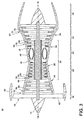
- FIG. 3 is a schematic cross-sectional diagram of a gas turbine engine 10 for an aircraft.
- the engine 10 has a generally longitudinally extending axis or centerline 12 extending forward 14 to aft 16.
- the engine 10 includes, in downstream serial flow relationship, a fan section 18 including a fan 20, a compressor section 22 including a booster or low pressure (LP) compressor 24 and a high pressure (HP) compressor 26, a combustion section 28 including a combustor 30, a turbine section 32 including a HP turbine 34, and a LP turbine 36, and an exhaust section 38.
- LP booster or low pressure
- HP high pressure
- the fan section 18 includes a fan casing 40 surrounding the fan 20.
- the fan 20 includes a plurality of fan blades 42 disposed radially about the centerline 12.
- the HP compressor 26, the combustor 30, and the HP turbine 34 form a core 44 of the engine 10 which generates combustion gases.
- the core 44 is surrounded by a core casing 46 which can be coupled with the fan casing 40.
- a LP shaft or spool 50 which is disposed coaxially about the centerline 12 of the engine 10 within the larger diameter annular HP spool 48, drivingly connects the LP turbine 36 to the LP compressor 24 and fan 20.
- the LP compressor 24 and the HP compressor 26 respectively include a plurality of compressor stages 52, 54, in which a set of compressor blades 56, 58 rotate relative to a corresponding set of static compressor vanes 60, 62 (also called a nozzle) to compress or pressurize the stream of fluid passing through the stage.
- a single compressor stage 52, 54 multiple compressor blades 56, 58 may be provided in a ring and may extend radially outwardly relative to the centerline 12, from a blade platform to a blade tip, while the corresponding static compressor vanes 60, 62 are positioned downstream of and adjacent to the rotating blades 56, 58. It is noted that the number of blades, vanes, and compressor stages shown in FIG. 3 were selected for illustrative purposes only, and that other numbers are possible.
- the HP turbine 34 and the LP turbine 36 respectively include a plurality of turbine stages 64, 66, in which a set of turbine blades 68, 70 are rotated relative to a corresponding set of static turbine vanes 72, 74 (also called a nozzle) to extract energy from the stream of fluid passing through the stage.
- a single turbine stage 64, 66 multiple turbine blades 68, 70 may be provided in a ring and may extend radially outwardly relative to the centerline 12, from a blade platform to a blade tip, while the corresponding static turbine vanes 72, 74 are positioned upstream of and adjacent to the rotating blades 68, 70. It is noted that the number of blades, vanes, and turbine stages shown in FIG. 3 were selected for illustrative purposes only, and that other numbers are possible.
- the rotating fan 20 supplies ambient air to the LP compressor 24, which then supplies pressurized ambient air to the HP compressor 26, which further pressurizes the ambient air.
- the pressurized air from the HP compressor 26 is mixed with fuel in combustor 30 and ignited, thereby generating combustion gases. Some work is extracted from these gases by the HP turbine 34, which drives the HP compressor 26.
- the combustion gases are discharged into the LP turbine 36, which extracts additional work to drive the LP compressor 24, and the exhaust gas is ultimately discharged from the engine 10 via the exhaust section 38.
- the driving of the LP turbine 36 drives the LP spool 50 to rotate the fan 20 and the LP compressor 24.
- Some of the ambient air supplied by the fan 20 may bypass the engine core 44 and be used for cooling of portions, especially hot portions, of the engine 10, and/or used to cool or power other aspects of the aircraft.
- the hot portions of the engine are normally downstream of the combustor 30, especially the turbine section 32, with the HP turbine 34 being the hottest portion as it is directly downstream of the combustion section 28.
- Other sources of cooling fluid may be, but is not limited to, fluid discharged from the LP compressor 24 or the HP compressor 26.
- FIG. 4 is a side section view of the combustor 30 and HP turbine 34 of the engine 10 from FIG. 3 .
- the combustor 30 includes a deflector 76 and a combustor liner 77. Adjacent to the turbine blade 68 of the turbine 34 in the axial direction are sets of radially-spaced, static turbine vanes 72, with adjacent vanes 72 forming nozzles therebetween. The nozzles turn combustion gas to better flow into the rotating blades so that the maximum energy may be extracted by the turbine 34.
- a cooling fluid flow C passes through the vanes 72 to cool the vanes 72 as hot combustion gas flow H passes along the exterior of the vanes 72.
- a shroud assembly 78 is adjacent to the rotating blade 68 to minimize flow loss in the turbine 34. Similar shroud assemblies can also be associated with the LP turbine 36, the LP compressor 24, or the HP compressor 26.
- One or more of the engine components of the engine 10 includes a film-cooled substrate in which a film hole of an embodiment disclosed further herein may be provided.
- Some non-limiting examples of the engine component having a film-cooled substrate can include the blades 68, 70, vanes or nozzles 72, 74, combustor deflector 76, combustor liner 77, or shroud assembly 78, described in FIGS. 3-4 .
- Other non-limiting examples where film cooling is used include turbine transition ducts and exhaust nozzles.
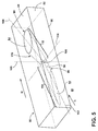
- FIG. 5 is a schematic, perspective view showing a portion of an engine component 80 according to a first embodiment of the invention.
- the engine component 80 may be an engine component of the engine 10 from FIG. 3 , and can be disposed in a flow of hot gas represented by arrow H.
- a cooling fluid flow, represented by arrow C may be supplied to cool the engine component.
- the cooling air can be ambient air supplied by the fan 20 which bypasses the engine core 44, fluid from the LP compressor 24, or fluid from the HP compressor 26.
- the engine component 80 includes a substrate 82 having a hot surface 84 facing the hot combustion gas flow H and a cooling surface 86 facing the cooling fluid C.
- the substrate 82 may form a wall of the engine component 80; the wall may be an exterior or interior wall of the engine component 80.
- the first engine component 80 can define at least one interior cavity 88 comprising the cooling surface 86.
- the hot surface 84 may be an exterior surface of the engine component 80. In the case of a gas turbine engine, the hot surface 84 may be exposed to gases having temperatures in the range of 1000 °C to 2000 °C.
- Suitable materials for the substrate 82 include, but are not limited to, steel, refractory metals such as titanium, or superalloys based on nickel, cobalt, or iron, and ceramic matrix composites.
- the superalloys can include those in equi-axed, directionally solidified, and single crystal structures.
- the engine component 80 further includes one or more film hole(s) 90 extending through the substrate 82 that provide fluid communication between the interior cavity 88 and the hot surface 84 of the engine component 80.
- the cooling fluid flow C is supplied to the interior cavity 88 and out of the film hole 90 to create a thin layer or film of cool air on the hot surface 84, protecting it from the hot combustion gas flow H. While only one film hole 90 is shown in FIG. 5 , it is understood that the engine component 80 may be provided with multiple film holes 90, which may be arranged in any desired configuration on the engine component 80.
- the film hole 90 can have an inlet 92 provided on the cooling surface 86 of the substrate 82, an outlet 94 provided on the hot surface 84, and a passage 96 connecting the inlet 92 and the outlet 94. Cooling fluid flow C enters the film hole 90 at the inlet 92 and passes through the passage 96 before exiting the film hole 90 at the outlet 94.
- the passage 96 can include a first portion 98 and a second portion 100 that is downstream of the first portion 98 with respect to the direction of cooling fluid flow C through the passage 96.
- Each portion 98, 100 of the passage can define a distinct centerline 102, 104, which is the longitudinal axis which passes through the geometric center of the cross-sectional area of the portion 98, 100.
- the term "axial direction” and variants thereof refer to the direction of cooling fluid flow C along the centerlines 102, 104 from the cooling surface 86 to the hot surface 84
- the term "radial direction” and variants thereof refer to the direction orthogonal to the centerlines 102, 104.
- the centerlines 102, 104 are linear; in other embodiments the centerlines 102, 104 may be non-linear or curved, depending on the shape of the film hole 90.
- the second portion 100 can be rotated relative to the first portion 98, such that the second centerline 104 is non-collinear with the first centerline 102 when viewed from the hot surface 84.
- the second centerline 104 can form a first angle A relative to the first centerline 102.
- the first angle A can be determined about an axis 106 perpendicular to a plane defined by the hot surface 84. When viewed from the hot surface 84 as in FIG. 6 , the axis 106 comes out of the page.
- the two centerlines 102, 104 can intersect at an intersection point 108.
- the intersection point 108 may lie within the passage 96 as illustrated herein.
- the axis 106 may pass through the intersection point 108, such that the vertex of the first angle A lies at the intersection point 108.
- the axis 106 may further be perpendicular to both the hot and cooling surfaces 84, 86.
- the substrate 82 is schematically shown as being generally planar, it is understood that the substrate 82 may be curved for many engine components 80. However, the curvature of the substrate 82 may be slight in comparison to the size of the film hole 90, and so for the purposes of discussion and illustration, the substrate 82 is shown as planar. Whether the substrate 82 is planar or curved, the axis 106 may be perpendicular to a plane defined by the hot surface 84 in the localized area of the substrate 82 through which the axis 106 passes. Furthermore, whether the substrate 82 is planar or curved local to the film hole 90, the hot and cooling surfaces 84, 86 may be parallel to each other as shown herein, or may lie in non-parallel planes.
- the first portion 98 can be inclined in a downstream direction of cooling fluid flow C through the passage 96 such that the first centerline 102 is non-orthogonal to the hot and cooling surfaces 84, 86.
- the second portion 100 can also be inclined in a downstream direction of cooling fluid flow C through the passage 96 such that the second centerline 104 is non-orthogonal to the hot and cooling surfaces 84, 86.
- either centerline 102, 104 may be orthogonal to one or both of the hot or cooling surfaces 84, 86.
- the first and second portions 98, 100 may have a circular or non-circular cross-sectional shape, where the cross-sectional shape is defined radially relative to the centerline 102, 104, respectively.
- Non-circular cross-sections may include, but not are limited to, rectangular, elliptical, trapezoidal, or other irregular shapes.
- the cross-sectional shape of the first and second portions 98, 100 may remain substantially constant long the centerline 102, 104, respectively, or may vary.
- the first and second portions 98, 100 may converge or diverge from the centerline 102, 104, respectively, along the axial direction.
- the first portion 98 can be an inlet portion of the passage 96, such that the first portion 98 includes the inlet 92.
- the second portion 100 can be an outlet portion of the passage 96, such that the second portion 100 includes the outlet 94 of the passage 96.
- the inlet portion 98 can extend from the inlet 92 to the intersection point 108, and the outlet portion 100 can extend from the intersection point 108 to the outlet 94.
- the first portion 98 is defined by a metering section 110 of the passage 96 for metering of the mass flow rate of the cooling fluid flow C
- the second portion 100 is defined by a diffusing section 112 in which the cooling fluid C may expand to form a wider cooling film.
- the diffusing section 112 may be in serial flow communication with the metering section 110.
- the metering section 110 can be provided at or near the inlet 92, while the diffusing section 112 can be defined at or near the outlet 94.
- the metering section 110 is a portion of the passage 96 with the smallest cross-sectional area perpendicular to the direction of cooling fluid flow C through the passage 96.
- the metering section 110 may be a discrete location at which the passage 96 has the smallest cross-sectional area, or an elongated section of the passage 96.
- An inlet to the metering section 110 communicates with the inlet 92 to the passage 96 and receives the cooling fluid flow C therefrom; in some embodiments of the invention, including the embodiment of FIG. 5 , the inlet to the metering section 110 may further be coincident with the inlet 92 to the passage 96.
- An outlet of the diffusing section 112 is coincident with the outlet 94 of the passage 96.
- An outlet of the metering section 110 is coincident with an inlet to the diffusing section 112, defines a transition where the cooling fluid flow C may begin to expand.
- intersection point 108 of the two centerlines 102, 104 can lie at the transition between the metering section 110 and the diffusing section 112.
- the metering section 110 is an elongated section of the passage 96, and the intersection point 108 lies at a distal or downstream end of the metering section 110.
- the overall shape of the second portion 100 shown in FIG. 5 is substantially similar conical in shape, such that, in the axial direction, the diffusing section 100 generally diverges from the second centerline 104 but has a substantially circular cross-section perpendicular to the second centerline 104.
- the second portion 100 may have a substantially elliptical or rectilinear cross-section.
- cooling fluid flow C enters the film hole 90 through the inlet 92 and passes through the metering section 98, turns at the intersection point 108, and passes through the diffusing section 100 before exiting the film hole 90 at the outlet 94 along the hot surface 84.
- the first angle A can represent a lateral change in the general direction of cooling fluid flow C though the passage 96.
- the first angle A can be the minimum angle between the first centerline 102 and the second centerline 104, such that it represents the magnitude or absolute value of the lateral change in direction, regardless of the direction in which the second portion 100 is rotated relative to the first portion 98, i.e. whether the second portion 100 is rotated up or down, relative to the view shown in FIG. 6 , about the axis 106.
- the first angle A can be acute. More specifically, the first angle A can be greater than 0 and less than 90 degrees. Still more specifically, the first angle A can range from 0 to 45 degrees.
- An acute angle A may lower the potential for material damage when manufacturing the film hole 90 and also lower the effects of manufacturing tolerances on cooling performance. Higher angles may also decrease the hole discharge coefficients such that the cooling fluid flow rate through the film hole decreases.
- the first angle A may be obtuse, i.e. greater than 90 degrees.
- FIG. 7 is a side view of the engine component 80, in which the film hole 90 is shown in dotted line.
- the second centerline 104 can form a second angle B relative to the first centerline 102.
- the second angle B can be determined about an axis 114 perpendicular to the axis 106.
- the axis 114 may thus be parallel to the plane defined by the hot surface 84.
- the axis 114 may pass through the intersection point 108, such that the vertex of the second angle B lies at the intersection point 108.
- the second angle B can represent a longitudinal change in the general direction of cooling fluid flow C through the passage 96.
- the second angle B can be the minimum angle between the first centerline 102 and the second centerline 104, such that it represents the magnitude or absolute value of the longitudinal change in direction, regardless of the direction in which the second portion 100 is rotated relative to the first portion 98, i.e. whether the second portion 100 is rotated up or down, relative to the view shown in FIG. 7 , about the axis 114.
- the second angle B can be acute. More specifically, the second angle B can be greater than 0 and less than 90 degrees. Still more specifically, the second angle B can range from 0 to 25 degrees. In other embodiments of the invention, the second angle B may be obtuse, i.e. greater than 90 degrees.
- the film hole lies along one or more centerlines which can be viewed in a cross-sectional plane.
- the centerlines 102, 104 of the film hole 90 cannot be viewed in a single cross-sectional view orthogonal to the hot surface 84.
- both centerlines 102, 104 can be viewed from a plane orthogonal to the hot surface 84 from outside the film hole 90.
- Embodiments of the present invention may be combined with shaping or contouring of the metering section and/or diffusing section of the film hole 90. Embodiments of the present invention may also be applied to film holes without a diffusing section. Embodiments of the present invention may also apply to slot-type film cooling, in which case the outlet 94 is provided within a slot on the hot surface 84. Further, in any of the above embodiments, a coating can be applied to the hot surface 84 of the substrate 82. Some non-limiting examples of coatings include a thermal barrier coating, an oxidation protection coating, or combinations thereof.
- the various embodiments of devices and methods related to the invention disclosed herein provide improved cooling for engine structures, particularly in a turbine component having film holes.
- One advantage that may be realized in the practice of some embodiments of the described systems is that the film hole has includes portions that are angled relative to each other when viewed from the hot surface. Previous shaped diffuser film holes have significant limitations when applied in compound angle orientations. By allowing the axes of differ portion of the film hole to be different, particularly the axes of the inlet and outlet portions, the outlet portion can be rotated from the inlet portion.
- the multi-axis film hole provides the ability to rotate the outlet portion as needed for maximum benefit, such as increasing film cooling effectiveness in highly curved airfoil regions, allowing film holes to be preferentially positioned within cooling passages without sacrificing the benefits of full shaping and coverage, and/or allowing decoupling of the flow entry and exit effects due to the relative orientation of the inlet or outlet of the film hole to the cooling fluid or hot combustion gas flow direction local to the film hole, respectively.
Abstract
Description
- Turbine engines, and particularly gas or combustion turbine engines, are rotary engines that extract energy from a flow of combusted gases passing through the engine onto a multitude of turbine blades. Gas turbine engines have been used for land and nautical locomotion and power generation, but are most commonly used for aeronautical applications such as for aircraft, including helicopters. In aircraft, gas turbine engines are used for propulsion of the aircraft. In terrestrial applications, turbine engines are often used for power generation.
- Gas turbine engines for aircraft are designed to operate at high temperatures to maximize engine efficiency, so cooling of certain engine components, such as the high pressure turbine and the low pressure turbine, may be necessary. Some engine components include film holes that supply a thin layer or film of cooling fluid on a hot surface of the engine component to protect the engine component from hot combustion gas. Typically, cooling is accomplished by ducting cooler air from the high and/or low pressure compressors to the engine components which require film cooling. The cooling air from the compressor is about 500 °C to 700 °C. While the compressor air is a high temperature, it is cooler relative to the air that passes through the combustion chamber, which may be around 1000 °C to 2000 °C.
- A prior
art film hole 200 in anengine component 202 is shown in cross-section inFIG. 1 . Theengine component 202 includes ahot surface 204 facing a hot combustion gas flow H and acooling surface 206 facing a cooling fluid flow C. During operation, the cooling fluid flow C is supplied out of thefilm hole 200 to create a thin layer or film of cool air on thehot surface 204, protecting it from the hot combustion gas flow H. Thefilm hole 200 includes aninlet 208 provided on acooling surface 206, anoutlet 210 provided on thehot surface 204, and apassage 212 connecting theinlet 208 and theoutlet 210. Thepassage 212 can includesections cooling surfaces FIG. 1 . In the illustrated embodiment, the sections include ametering section 214 for metering of the mass flow rate of the cooling fluid flow C, and a diffusingsection 216 in which the cooling fluid C may expand to form a wider cooling film. - The
film hole 200 lies along a longitudinal axis of thepassage 212, also referred to herein as thecenterline 218, which passes through the geometric center of the cross-sectional area of themetering section 214. The diffusingsection 216 can define itsown centerline 220, which passes through the geometric center of the cross-sectional area of the diffusingsection 216. The twocenterlines cooling surfaces FIG. 1 . When viewed from thehot surface 204, as shown inFIG. 2 , thecenterlines passage 212. - In one aspect, the invention relates to an engine component for a gas turbine engine, the gas turbine engine generating hot combustion gas flow, having a substrate having a hot surface facing the hot combustion gas flow and a cooling surface facing a cooling fluid flow, and a film hole extending through the substrate and having an inlet provided on the cooling surface, an outlet provided on the hot surface, and a passage connecting the inlet and the outlet, wherein the passage comprises an inlet portion defining an inlet portion centerline and an outlet portion defining an outlet portion centerline, which forms a first angle relative to the inlet portion centerline such that the outlet portion centerline is non-collinear with the inlet portion centerline when viewed from the hot surface.
- In another aspect, the invention relates to an engine component for a gas turbine engine, the gas turbine engine generating hot combustion gas flow, having a substrate having a hot surface facing the hot combustion gas flow and a cooling surface facing a cooling fluid flow, and a film hole extending through the substrate and having an inlet provided on the cooling surface, an outlet provided on the hot surface, and a passage connecting the inlet and the outlet, wherein the passage comprises a first portion defining a first centerline and a second portion, located downstream of the first portion relative to the direction of the cooling fluid flow through the passage, defining a second centerline, wherein the second centerline forms a first angle relative to the first centerline about an axis perpendicular to a plane defined by the hot surface.
- In yet another aspect, the invention relates to an engine component for a gas turbine engine, the gas turbine engine generating hot combustion gas flow, having a substrate having a hot surface facing the hot combustion gas and a cooling surface facing a cooling fluid flow, and a film hole extending through the substrate and having an inlet provided on the cooling surface, an outlet provided on the hot surface, and a passage connecting the inlet and the outlet, wherein the passage comprises an inlet portion including the inlet and defining an inlet portion centerline, and an outlet portion including the outlet and defining an outlet portion centerline, and wherein the outlet portion centerline intersects the inlet portion centerline at a point and forms a first angle relative to the inlet portion centerline about an axis passing through the point and perpendicular to a plane defined by the hot surface.
- In the drawings:
-
FIG. 1 is a schematic, sectional view through a film hole of an engine component according to the prior art. -
FIG. 2 is a top view of the hot surface of the prior art engine component fromFIG. 1 . -
FIG. 3 is a schematic cross-sectional diagram of a gas turbine engine for an aircraft. -
FIG. 4 is a side section view of a combustor and a high pressure turbine of the engine fromFIG. 3 . -
FIG. 5 is a schematic, perspective view of an engine component having a film hole according to a first embodiment of the invention. -
FIG. 6 is a top view of a hot surface of the engine component fromFIG. 5 . -
FIG. 7 is a side view of the engine component fromFIG. 5 . - The described embodiments of the present invention are directed to a film-cooled engine component, particularly in a gas turbine engine. For purposes of illustration, aspects of the present invention will be described with respect to an aircraft gas turbine engine. It will be understood, however, that the invention is not so limited and may have general applicability in non-aircraft applications, such as other mobile applications and non-mobile industrial, commercial, and residential applications.
-
FIG. 3 is a schematic cross-sectional diagram of agas turbine engine 10 for an aircraft. Theengine 10 has a generally longitudinally extending axis orcenterline 12 extending forward 14 toaft 16. Theengine 10 includes, in downstream serial flow relationship, afan section 18 including afan 20, acompressor section 22 including a booster or low pressure (LP)compressor 24 and a high pressure (HP)compressor 26, acombustion section 28 including acombustor 30, aturbine section 32 including a HPturbine 34, and aLP turbine 36, and an exhaust section 38. - The
fan section 18 includes afan casing 40 surrounding thefan 20. Thefan 20 includes a plurality offan blades 42 disposed radially about thecenterline 12. - The HP
compressor 26, thecombustor 30, and the HPturbine 34 form acore 44 of theengine 10 which generates combustion gases. Thecore 44 is surrounded by acore casing 46 which can be coupled with thefan casing 40. - A HP shaft or
spool 48 disposed coaxially about thecenterline 12 of theengine 10 drivingly connects the HPturbine 34 to the HPcompressor 26. A LP shaft orspool 50, which is disposed coaxially about thecenterline 12 of theengine 10 within the larger diameter annular HPspool 48, drivingly connects theLP turbine 36 to theLP compressor 24 andfan 20. - The
LP compressor 24 and the HPcompressor 26 respectively include a plurality ofcompressor stages compressor blades static compressor vanes 60, 62 (also called a nozzle) to compress or pressurize the stream of fluid passing through the stage. In asingle compressor stage multiple compressor blades centerline 12, from a blade platform to a blade tip, while the corresponding static compressor vanes 60, 62 are positioned downstream of and adjacent to therotating blades FIG. 3 were selected for illustrative purposes only, and that other numbers are possible. - The HP
turbine 34 and theLP turbine 36 respectively include a plurality ofturbine stages turbine blades static turbine vanes 72, 74 (also called a nozzle) to extract energy from the stream of fluid passing through the stage. In asingle turbine stage multiple turbine blades centerline 12, from a blade platform to a blade tip, while the corresponding static turbine vanes 72, 74 are positioned upstream of and adjacent to therotating blades FIG. 3 were selected for illustrative purposes only, and that other numbers are possible. - In operation, the rotating
fan 20 supplies ambient air to theLP compressor 24, which then supplies pressurized ambient air to the HPcompressor 26, which further pressurizes the ambient air. The pressurized air from the HPcompressor 26 is mixed with fuel incombustor 30 and ignited, thereby generating combustion gases. Some work is extracted from these gases by the HPturbine 34, which drives the HPcompressor 26. The combustion gases are discharged into theLP turbine 36, which extracts additional work to drive theLP compressor 24, and the exhaust gas is ultimately discharged from theengine 10 via the exhaust section 38. The driving of theLP turbine 36 drives theLP spool 50 to rotate thefan 20 and theLP compressor 24. - Some of the ambient air supplied by the
fan 20 may bypass theengine core 44 and be used for cooling of portions, especially hot portions, of theengine 10, and/or used to cool or power other aspects of the aircraft. In the context of a turbine engine, the hot portions of the engine are normally downstream of thecombustor 30, especially theturbine section 32, with the HPturbine 34 being the hottest portion as it is directly downstream of thecombustion section 28. Other sources of cooling fluid may be, but is not limited to, fluid discharged from theLP compressor 24 or the HPcompressor 26. -
FIG. 4 is a side section view of thecombustor 30 and HPturbine 34 of theengine 10 fromFIG. 3 . Thecombustor 30 includes adeflector 76 and acombustor liner 77. Adjacent to theturbine blade 68 of theturbine 34 in the axial direction are sets of radially-spaced,static turbine vanes 72, withadjacent vanes 72 forming nozzles therebetween. The nozzles turn combustion gas to better flow into the rotating blades so that the maximum energy may be extracted by theturbine 34. A cooling fluid flow C passes through thevanes 72 to cool thevanes 72 as hot combustion gas flow H passes along the exterior of thevanes 72. Ashroud assembly 78 is adjacent to the rotatingblade 68 to minimize flow loss in theturbine 34. Similar shroud assemblies can also be associated with theLP turbine 36, theLP compressor 24, or the HPcompressor 26. - One or more of the engine components of the
engine 10 includes a film-cooled substrate in which a film hole of an embodiment disclosed further herein may be provided. Some non-limiting examples of the engine component having a film-cooled substrate can include theblades nozzles combustor deflector 76,combustor liner 77, orshroud assembly 78, described inFIGS. 3-4 . Other non-limiting examples where film cooling is used include turbine transition ducts and exhaust nozzles. -
FIG. 5 is a schematic, perspective view showing a portion of anengine component 80 according to a first embodiment of the invention. Theengine component 80 may be an engine component of theengine 10 fromFIG. 3 , and can be disposed in a flow of hot gas represented by arrow H. A cooling fluid flow, represented by arrow C may be supplied to cool the engine component. As discussed above with respect toFIGS. 3-4 , in the context of a turbine engine, the cooling air can be ambient air supplied by thefan 20 which bypasses theengine core 44, fluid from theLP compressor 24, or fluid from theHP compressor 26. - The
engine component 80 includes asubstrate 82 having ahot surface 84 facing the hot combustion gas flow H and a cooling surface 86 facing the cooling fluid C. Thesubstrate 82 may form a wall of theengine component 80; the wall may be an exterior or interior wall of theengine component 80. Thefirst engine component 80 can define at least oneinterior cavity 88 comprising the cooling surface 86. Thehot surface 84 may be an exterior surface of theengine component 80. In the case of a gas turbine engine, thehot surface 84 may be exposed to gases having temperatures in the range of 1000 °C to 2000 °C. Suitable materials for thesubstrate 82 include, but are not limited to, steel, refractory metals such as titanium, or superalloys based on nickel, cobalt, or iron, and ceramic matrix composites. The superalloys can include those in equi-axed, directionally solidified, and single crystal structures. - The
engine component 80 further includes one or more film hole(s) 90 extending through thesubstrate 82 that provide fluid communication between theinterior cavity 88 and thehot surface 84 of theengine component 80. During operation, the cooling fluid flow C is supplied to theinterior cavity 88 and out of thefilm hole 90 to create a thin layer or film of cool air on thehot surface 84, protecting it from the hot combustion gas flow H. While only onefilm hole 90 is shown inFIG. 5 , it is understood that theengine component 80 may be provided with multiple film holes 90, which may be arranged in any desired configuration on theengine component 80. - The
film hole 90 can have aninlet 92 provided on the cooling surface 86 of thesubstrate 82, anoutlet 94 provided on thehot surface 84, and apassage 96 connecting theinlet 92 and theoutlet 94. Cooling fluid flow C enters thefilm hole 90 at theinlet 92 and passes through thepassage 96 before exiting thefilm hole 90 at theoutlet 94. - The
passage 96 can include afirst portion 98 and asecond portion 100 that is downstream of thefirst portion 98 with respect to the direction of cooling fluid flow C through thepassage 96. Eachportion distinct centerline portion film hole 90, the term "axial direction" and variants thereof refer to the direction of cooling fluid flow C along thecenterlines hot surface 84, and the term "radial direction" and variants thereof refer to the direction orthogonal to thecenterlines centerlines centerlines film hole 90. - With additional reference to
FIG. 6 , which is a top view of thehot surface 84 of theengine component 80 fromFIG. 5 , thesecond portion 100 can be rotated relative to thefirst portion 98, such that thesecond centerline 104 is non-collinear with thefirst centerline 102 when viewed from thehot surface 84. Thesecond centerline 104 can form a first angle A relative to thefirst centerline 102. In the illustrated embodiment, the first angle A can be determined about anaxis 106 perpendicular to a plane defined by thehot surface 84. When viewed from thehot surface 84 as inFIG. 6 , theaxis 106 comes out of the page. - Many prior art film holes, including the
film hole 200 shown inFIGS. 1-2 , lie along a single centerline or collinear centerlines when viewed from above. Here, because thesecond portion 100 is rotated out of the plane in which thefirst centerline 104 lies, thecenterlines hot surface 84. The rotatedsecond portion 100 provides a lateral change in direction for the cooling fluid flow C through thepassage 96. One general benefit to this is the added degree of design freedom and/or flexibility. Theinlet 92 andoutlet 94 are no longer constrained to be on the same collinear axes. Theinlet 92 can be placed as needed with respect to internal features or walls of theengine component 80, while still maintaining a desired beneficial location for theoutlet 94. - The two
centerlines intersection point 108. Theintersection point 108 may lie within thepassage 96 as illustrated herein. Theaxis 106 may pass through theintersection point 108, such that the vertex of the first angle A lies at theintersection point 108. In addition to passing through theintersection point 108, in some embodiments of the invention theaxis 106 may further be perpendicular to both the hot and coolingsurfaces 84, 86. - It is noted that, in any of the embodiments discussed herein, although the
substrate 82 is schematically shown as being generally planar, it is understood that thesubstrate 82 may be curved formany engine components 80. However, the curvature of thesubstrate 82 may be slight in comparison to the size of thefilm hole 90, and so for the purposes of discussion and illustration, thesubstrate 82 is shown as planar. Whether thesubstrate 82 is planar or curved, theaxis 106 may be perpendicular to a plane defined by thehot surface 84 in the localized area of thesubstrate 82 through which theaxis 106 passes. Furthermore, whether thesubstrate 82 is planar or curved local to thefilm hole 90, the hot and coolingsurfaces 84, 86 may be parallel to each other as shown herein, or may lie in non-parallel planes. - The
first portion 98 can be inclined in a downstream direction of cooling fluid flow C through thepassage 96 such that thefirst centerline 102 is non-orthogonal to the hot and coolingsurfaces 84, 86. Thesecond portion 100 can also be inclined in a downstream direction of cooling fluid flow C through thepassage 96 such that thesecond centerline 104 is non-orthogonal to the hot and coolingsurfaces 84, 86. Alternatively, eithercenterline surfaces 84, 86. - The first and
second portions centerline second portions centerline second portions centerline - In the embodiment illustrated, the
first portion 98 can be an inlet portion of thepassage 96, such that thefirst portion 98 includes theinlet 92. Thesecond portion 100 can be an outlet portion of thepassage 96, such that thesecond portion 100 includes theoutlet 94 of thepassage 96. Theinlet portion 98 can extend from theinlet 92 to theintersection point 108, and theoutlet portion 100 can extend from theintersection point 108 to theoutlet 94. - More specifically, in the illustrated embodiment, the
first portion 98 is defined by ametering section 110 of thepassage 96 for metering of the mass flow rate of the cooling fluid flow C, and thesecond portion 100 is defined by a diffusingsection 112 in which the cooling fluid C may expand to form a wider cooling film. The diffusingsection 112 may be in serial flow communication with themetering section 110. Themetering section 110 can be provided at or near theinlet 92, while the diffusingsection 112 can be defined at or near theoutlet 94. - The
metering section 110 is a portion of thepassage 96 with the smallest cross-sectional area perpendicular to the direction of cooling fluid flow C through thepassage 96. Themetering section 110 may be a discrete location at which thepassage 96 has the smallest cross-sectional area, or an elongated section of thepassage 96. - An inlet to the
metering section 110 communicates with theinlet 92 to thepassage 96 and receives the cooling fluid flow C therefrom; in some embodiments of the invention, including the embodiment ofFIG. 5 , the inlet to themetering section 110 may further be coincident with theinlet 92 to thepassage 96. An outlet of the diffusingsection 112 is coincident with theoutlet 94 of thepassage 96. An outlet of themetering section 110 is coincident with an inlet to thediffusing section 112, defines a transition where the cooling fluid flow C may begin to expand. - The
intersection point 108 of the twocenterlines metering section 110 and the diffusingsection 112. In the illustrated embodiment, themetering section 110 is an elongated section of thepassage 96, and theintersection point 108 lies at a distal or downstream end of themetering section 110. - The overall shape of the
second portion 100 shown inFIG. 5 is substantially similar conical in shape, such that, in the axial direction, the diffusingsection 100 generally diverges from thesecond centerline 104 but has a substantially circular cross-section perpendicular to thesecond centerline 104. Alternatively, thesecond portion 100 may have a substantially elliptical or rectilinear cross-section. - In operation, cooling fluid flow C enters the
film hole 90 through theinlet 92 and passes through themetering section 98, turns at theintersection point 108, and passes through the diffusingsection 100 before exiting thefilm hole 90 at theoutlet 94 along thehot surface 84. The first angle A can represent a lateral change in the general direction of cooling fluid flow C though thepassage 96. The first angle A can be the minimum angle between thefirst centerline 102 and thesecond centerline 104, such that it represents the magnitude or absolute value of the lateral change in direction, regardless of the direction in which thesecond portion 100 is rotated relative to thefirst portion 98, i.e. whether thesecond portion 100 is rotated up or down, relative to the view shown inFIG. 6 , about theaxis 106. - In one example, the first angle A can be acute. More specifically, the first angle A can be greater than 0 and less than 90 degrees. Still more specifically, the first angle A can range from 0 to 45 degrees. An acute angle A may lower the potential for material damage when manufacturing the
film hole 90 and also lower the effects of manufacturing tolerances on cooling performance. Higher angles may also decrease the hole discharge coefficients such that the cooling fluid flow rate through the film hole decreases. In other embodiments of the invention, the first angle A may be obtuse, i.e. greater than 90 degrees. -
FIG. 7 is a side view of theengine component 80, in which thefilm hole 90 is shown in dotted line. When viewed from a plane orthogonal to thehot surface 84, thesecond centerline 104 can form a second angle B relative to thefirst centerline 102. In the illustrated embodiment, the second angle B can be determined about anaxis 114 perpendicular to theaxis 106. Theaxis 114 may thus be parallel to the plane defined by thehot surface 84. Theaxis 114 may pass through theintersection point 108, such that the vertex of the second angle B lies at theintersection point 108. - The second angle B can represent a longitudinal change in the general direction of cooling fluid flow C through the
passage 96. The second angle B can be the minimum angle between thefirst centerline 102 and thesecond centerline 104, such that it represents the magnitude or absolute value of the longitudinal change in direction, regardless of the direction in which thesecond portion 100 is rotated relative to thefirst portion 98, i.e. whether thesecond portion 100 is rotated up or down, relative to the view shown inFIG. 7 , about theaxis 114. - In one example, the second angle B can be acute. More specifically, the second angle B can be greater than 0 and less than 90 degrees. Still more specifically, the second angle B can range from 0 to 25 degrees. In other embodiments of the invention, the second angle B may be obtuse, i.e. greater than 90 degrees.
- It is noted that for many prior art film holes, including the film hole shown in
FIGS. 1-2 , the film hole lies along one or more centerlines which can be viewed in a cross-sectional plane. Here, because thesecond portion 100 is rotated out of plane with thefirst portion 98, thecenterlines film hole 90 cannot be viewed in a single cross-sectional view orthogonal to thehot surface 84. However, bothcenterlines hot surface 84 from outside thefilm hole 90. - Embodiments of the present invention may be combined with shaping or contouring of the metering section and/or diffusing section of the
film hole 90. Embodiments of the present invention may also be applied to film holes without a diffusing section. Embodiments of the present invention may also apply to slot-type film cooling, in which case theoutlet 94 is provided within a slot on thehot surface 84. Further, in any of the above embodiments, a coating can be applied to thehot surface 84 of thesubstrate 82. Some non-limiting examples of coatings include a thermal barrier coating, an oxidation protection coating, or combinations thereof. - The various embodiments of devices and methods related to the invention disclosed herein provide improved cooling for engine structures, particularly in a turbine component having film holes. One advantage that may be realized in the practice of some embodiments of the described systems is that the film hole has includes portions that are angled relative to each other when viewed from the hot surface. Previous shaped diffuser film holes have significant limitations when applied in compound angle orientations. By allowing the axes of differ portion of the film hole to be different, particularly the axes of the inlet and outlet portions, the outlet portion can be rotated from the inlet portion. The multi-axis film hole provides the ability to rotate the outlet portion as needed for maximum benefit, such as increasing film cooling effectiveness in highly curved airfoil regions, allowing film holes to be preferentially positioned within cooling passages without sacrificing the benefits of full shaping and coverage, and/or allowing decoupling of the flow entry and exit effects due to the relative orientation of the inlet or outlet of the film hole to the cooling fluid or hot combustion gas flow direction local to the film hole, respectively.
- This written description uses examples to disclose the invention, including the best mode, and also to enable any person skilled in the art to practice the invention, including making and using any devices or systems and performing any incorporated methods. The patentable scope of the invention is defined by the claims, and may include other examples that occur to those skilled in the art. Such other examples are intended to be within the scope of the claims if they have structural elements that do not differ from the literal language of the claims, or if they include equivalent structural elements with insubstantial differences from the literal languages of the claims.
- Various aspects and embodiments of the present invention are defined by the following numbered clauses:
- 1. An engine component for a gas turbine engine, the gas turbine engine generating hot combustion gas flow, comprising:
- a substrate having a hot surface facing the hot combustion gas flow and a cooling surface facing a cooling fluid flow; and
- a film hole extending through the substrate and having an inlet provided on the cooling surface, an outlet provided on the hot surface, and a passage connecting the inlet and the outlet;
- wherein the passage comprises an inlet portion defining an inlet portion centerline and an outlet portion defining an outlet portion centerline, which forms a first angle relative to the inlet portion centerline such that the outlet portion centerline is non-collinear with the inlet portion centerline when viewed from the hot surface.
- 2. The engine component of clause 1, wherein the outlet portion centerline forms a second angle relative to the inlet portion centerline when viewed from a plane orthogonal to the hot surface.
- 3. The engine component of any preceding clause, wherein at least one of the first and second angles are acute.
- 4. The engine component of any preceding clause, wherein both of the first and second angles are acute.
- 5. The engine component of any preceding clause, wherein the first angle is about an axis perpendicular to a plane defined by the hot surface.
- 6. The engine component of any preceding clause, wherein the axis passes through an intersection of the inlet portion centerline and the outlet portion centerline.
- 7. The engine component of any preceding clause, wherein the passage comprises a metering section defining the inlet portion and a diffusing section defining the outlet portion.
- 8. The engine component of any preceding clause, wherein the metering section includes the inlet and the diffusing section includes the outlet.
- 9. The engine component of any preceding clause, wherein the inlet portion centerline and the outlet portion centerline are linear.
- 10. An engine component for a gas turbine engine, the gas turbine engine generating hot combustion gas flow, comprising:
- a substrate having a hot surface facing the hot combustion gas flow and a cooling surface facing a cooling fluid flow; and
- a film hole extending through the substrate and having an inlet provided on the cooling surface, an outlet provided on the hot surface, and a passage connecting the inlet and the outlet;
- wherein the passage comprises:
- a first portion defining a first centerline; and
- a second portion, located downstream of the first portion relative to the direction of the cooling fluid flow through the passage, defining a second centerline;
- wherein the second centerline forms a first angle relative to the first centerline about an axis perpendicular to a plane defined by the hot surface.
- 11. The engine component of any preceding clause, wherein the second centerline forms a second angle relative to the first centerline when viewed from a plane orthogonal to the hot surface.
- 12. The engine component of any preceding clause, wherein at least one of the first and second angles are acute.
- 13. The engine component of any preceding clause, wherein both of the first and second angles are acute.
- 14. The engine component of any preceding clause, wherein the axis passes through an intersection of the first centerline and the second centerline.
- 15. The engine component of any preceding clause, wherein the passage comprises a metering section defining the first portion and a diffusing section defining the second portion.
- 16. The engine component of any preceding clause, wherein the metering section includes the inlet and the diffusing section includes the outlet.
- 17. The engine component of any preceding clause, wherein the first centerline and the second centerline are linear.
- 18. An engine component for a gas turbine engine, the gas turbine engine generating hot combustion gas flow, comprising:
- a substrate having a hot surface facing the hot combustion gas and a cooling surface facing a cooling fluid flow; and
- a film hole extending through the substrate and having an inlet provided on the cooling surface, an outlet provided on the hot surface, and a passage connecting the inlet and the outlet;
- wherein the passage comprises an inlet portion including the inlet and defining an inlet portion centerline, and an outlet portion including the outlet and defining an outlet portion centerline; and
- wherein the outlet portion centerline intersects the inlet portion centerline at a point and forms a first angle relative to the inlet portion centerline about an axis passing through the point and perpendicular to a plane defined by the hot surface.
- 19. The engine component of any preceding clause, wherein the outlet portion centerline forms a second angle relative to the inlet portion centerline when viewed from a plane orthogonal to the hot surface.
- 20. The engine component of any preceding clause, wherein the passage comprises a metering section defining the inlet portion and a diffusing section defining the outlet portion.
Claims (11)
- An engine component (80) for a gas turbine engine, the gas turbine engine generating hot combustion gas flow, comprising:a substrate (82) having a hot surface (84) facing the hot combustion gas flow and a cooling surface (86) facing a cooling fluid flow; anda film hole (90) extending through the substrate (82) and having an inlet (92) provided on the cooling surface (86), an outlet (94) provided on the hot surface (84), and a passage (96) connecting the inlet (92) and the outlet (94);wherein the passage (96) comprises an inlet portion (98) defining an inlet portion centerline (102) and an outlet portion (100) defining an outlet portion centerline (104), which forms a first angle relative to the inlet portion centerline (102) such that the outlet portion centerline (104) is non-collinear with the inlet portion centerline (102) when viewed from the hot surface (84).
- The engine component (80) of claim 1, wherein the outlet portion centerline (104) forms a second angle relative to the inlet portion centerline (102) when viewed from a plane orthogonal to the hot surface (84).
- The engine component (80) of claim 2, wherein at least one of the first and second angles are acute.
- The engine component (80) of claim 3, wherein both of the first and second angles are acute.
- The engine component (80) of any of claims 2 to 4, wherein the first angle is about an axis (106) perpendicular to a plane defined by the hot surface (84).
- The engine component (80) of claim 5, wherein the axis (106) passes through an intersection (108) of the inlet portion centerline (102) and the outlet portion centerline (104).
- The engine component (80) of any preceding claim, wherein the passage (96) comprises a metering section (110) defining the inlet portion (98) and a diffusing section (112) defining the outlet portion (100).
- The engine component (80) of claim 7, wherein the metering section (110) includes the inlet (92) and the diffusing section (112) includes the outlet (94).
- The engine component (80) of any preceding claim, wherein the inlet portion centerline (102) and the outlet portion centerline (104) are linear.
- The engine component (80) of any preceding claim, wherein the outlet portion (100) is located downstream of the inlet portion (98) relative to the direction of the cooling fluid flow through the passage (96); and
wherein the outlet portion centerline (104) forms the first angle relative to the inlet portion centerline (102) about an axis (106) perpendicular to a plane defined by the hot surface (84). - The engine component (80) of any preceding claim, wherein the outlet portion centerline (104) intersects the inlet portion centerline (102) at a point and forms the first angle relative to the inlet portion centerline (102) about an axis passing through the point and perpendicular to a plane defined by the hot surface (84).
Applications Claiming Priority (1)
| Application Number | Priority Date | Filing Date | Title |
|---|---|---|---|
| US14/629,986 US20160245094A1 (en) | 2015-02-24 | 2015-02-24 | Engine component |
Publications (1)
| Publication Number | Publication Date |
|---|---|
| EP3061911A1 true EP3061911A1 (en) | 2016-08-31 |
Family
ID=55409725
Family Applications (1)
| Application Number | Title | Priority Date | Filing Date |
|---|---|---|---|
| EP16155996.8A Withdrawn EP3061911A1 (en) | 2015-02-24 | 2016-02-16 | Engine component |
Country Status (6)
| Country | Link |
|---|---|
| US (1) | US20160245094A1 (en) |
| EP (1) | EP3061911A1 (en) |
| JP (1) | JP2016166606A (en) |
| CN (1) | CN105909317A (en) |
| BR (1) | BR102016002830A2 (en) |
| CA (1) | CA2920563A1 (en) |
Cited By (2)
| Publication number | Priority date | Publication date | Assignee | Title |
|---|---|---|---|---|
| EP3255248A1 (en) * | 2016-04-14 | 2017-12-13 | General Electric Company | Engine component for a turbine engine |
| EP3660400A1 (en) * | 2018-11-27 | 2020-06-03 | Honeywell International Inc. | Plug resistant effusion holes for gas turbine engine |
Families Citing this family (12)
| Publication number | Priority date | Publication date | Assignee | Title |
|---|---|---|---|---|
| FR3037107B1 (en) * | 2015-06-03 | 2019-11-15 | Safran Aircraft Engines | ANNULAR ROOM OF COMBUSTION CHAMBER WITH OPTIMIZED COOLING |
| US10626796B2 (en) * | 2015-08-17 | 2020-04-21 | United Technologies Corporation | Film cooling passage with multidimensional diffusion |
| US20180230812A1 (en) * | 2017-01-13 | 2018-08-16 | General Electric Company | Film hole arrangement for a turbine engine |
| US10830435B2 (en) | 2018-02-06 | 2020-11-10 | Raytheon Technologies Corporation | Diffusing hole for rail effusion |
| US11009230B2 (en) | 2018-02-06 | 2021-05-18 | Raytheon Technologies Corporation | Undercut combustor panel rail |
| US11248791B2 (en) | 2018-02-06 | 2022-02-15 | Raytheon Technologies Corporation | Pull-plane effusion combustor panel |
| US11022307B2 (en) * | 2018-02-22 | 2021-06-01 | Raytheon Technology Corporation | Gas turbine combustor heat shield panel having multi-direction hole for rail effusion cooling |
| JP7149156B2 (en) * | 2018-10-09 | 2022-10-06 | 三菱重工業株式会社 | gas turbine combustor and gas turbine |
| US10822958B2 (en) * | 2019-01-16 | 2020-11-03 | General Electric Company | Component for a turbine engine with a cooling hole |
| KR102318874B1 (en) * | 2019-02-22 | 2021-10-29 | 인하대학교 산학협력단 | Shape structure of converging divergent film cooling holes for cooling gas turbine blades |
| JP7175298B2 (en) * | 2020-07-27 | 2022-11-18 | 三菱重工業株式会社 | gas turbine combustor |
| US11674686B2 (en) | 2021-05-11 | 2023-06-13 | Honeywell International Inc. | Coating occlusion resistant effusion cooling holes for gas turbine engine |
Citations (6)
| Publication number | Priority date | Publication date | Assignee | Title |
|---|---|---|---|---|
| EP0945593A1 (en) * | 1998-03-23 | 1999-09-29 | Abb Research Ltd. | Film-cooling hole |
| US20060073015A1 (en) * | 2004-10-01 | 2006-04-06 | Alstom Technology Ltd. | Gas turbine airfoil film cooling hole |
| EP1898051A2 (en) * | 2006-08-25 | 2008-03-12 | ALSTOM Technology Ltd | Gas turbine airfoil with leading edge cooling |
| EP2075410A2 (en) * | 2007-12-28 | 2009-07-01 | General Electric Company | Method for forming cooling holes and turbine airfoil with hybrid-formed cooling holes |
| US8057180B1 (en) * | 2008-11-07 | 2011-11-15 | Florida Turbine Technologies, Inc. | Shaped film cooling hole for turbine airfoil |
| EP2987954A1 (en) * | 2014-08-15 | 2016-02-24 | United Technologies Corporation | Gas turbine component with showerhead cooling hole layout |
Family Cites Families (11)
| Publication number | Priority date | Publication date | Assignee | Title |
|---|---|---|---|---|
| US6234755B1 (en) * | 1999-10-04 | 2001-05-22 | General Electric Company | Method for improving the cooling effectiveness of a gaseous coolant stream, and related articles of manufacture |
| US7007481B2 (en) * | 2003-09-10 | 2006-03-07 | General Electric Company | Thick coated combustor liner |
| US20080005903A1 (en) * | 2006-07-05 | 2008-01-10 | United Technologies Corporation | External datum system and film hole positioning using core locating holes |
| FR2921463B1 (en) * | 2007-09-26 | 2013-12-06 | Snecma | COMBUSTION CHAMBER OF A TURBOMACHINE |
| DE102009007164A1 (en) * | 2009-02-03 | 2010-08-12 | Rolls-Royce Deutschland Ltd & Co Kg | A method of forming a cooling air opening in a wall of a gas turbine combustor and combustor wall made by the method |
| JP4954309B2 (en) * | 2010-03-24 | 2012-06-13 | 川崎重工業株式会社 | Double jet film cooling structure |
| US20130074471A1 (en) * | 2011-09-22 | 2013-03-28 | General Electric Company | Turbine combustor and method for temperature control and damping a portion of a combustor |
| US8733111B2 (en) * | 2012-02-15 | 2014-05-27 | United Technologies Corporation | Cooling hole with asymmetric diffuser |
| US8724195B2 (en) * | 2012-04-11 | 2014-05-13 | Kyocera Document Solutions Inc. | Accommodating dynamic ranges in a cone space model |
| US9765968B2 (en) * | 2013-01-23 | 2017-09-19 | Honeywell International Inc. | Combustors with complex shaped effusion holes |
| US10480787B2 (en) * | 2015-03-26 | 2019-11-19 | United Technologies Corporation | Combustor wall cooling channel formed by additive manufacturing |
-
2015
- 2015-02-24 US US14/629,986 patent/US20160245094A1/en not_active Abandoned
-
2016
- 2016-02-11 BR BR102016002830A patent/BR102016002830A2/en not_active Application Discontinuation
- 2016-02-11 CA CA2920563A patent/CA2920563A1/en not_active Abandoned
- 2016-02-16 EP EP16155996.8A patent/EP3061911A1/en not_active Withdrawn
- 2016-02-18 JP JP2016028476A patent/JP2016166606A/en active Pending
- 2016-02-24 CN CN201610100511.XA patent/CN105909317A/en active Pending
Patent Citations (6)
| Publication number | Priority date | Publication date | Assignee | Title |
|---|---|---|---|---|
| EP0945593A1 (en) * | 1998-03-23 | 1999-09-29 | Abb Research Ltd. | Film-cooling hole |
| US20060073015A1 (en) * | 2004-10-01 | 2006-04-06 | Alstom Technology Ltd. | Gas turbine airfoil film cooling hole |
| EP1898051A2 (en) * | 2006-08-25 | 2008-03-12 | ALSTOM Technology Ltd | Gas turbine airfoil with leading edge cooling |
| EP2075410A2 (en) * | 2007-12-28 | 2009-07-01 | General Electric Company | Method for forming cooling holes and turbine airfoil with hybrid-formed cooling holes |
| US8057180B1 (en) * | 2008-11-07 | 2011-11-15 | Florida Turbine Technologies, Inc. | Shaped film cooling hole for turbine airfoil |
| EP2987954A1 (en) * | 2014-08-15 | 2016-02-24 | United Technologies Corporation | Gas turbine component with showerhead cooling hole layout |
Cited By (4)
| Publication number | Priority date | Publication date | Assignee | Title |
|---|---|---|---|---|
| EP3255248A1 (en) * | 2016-04-14 | 2017-12-13 | General Electric Company | Engine component for a turbine engine |
| EP3660400A1 (en) * | 2018-11-27 | 2020-06-03 | Honeywell International Inc. | Plug resistant effusion holes for gas turbine engine |
| US11085641B2 (en) | 2018-11-27 | 2021-08-10 | Honeywell International Inc. | Plug resistant effusion holes for gas turbine engine |
| US11519604B2 (en) | 2018-11-27 | 2022-12-06 | Honeywell International Inc. | Plug resistant effusion holes for gas turbine engine |
Also Published As
| Publication number | Publication date |
|---|---|
| CA2920563A1 (en) | 2016-08-24 |
| BR102016002830A2 (en) | 2016-10-11 |
| JP2016166606A (en) | 2016-09-15 |
| CN105909317A (en) | 2016-08-31 |
| US20160245094A1 (en) | 2016-08-25 |
Similar Documents
| Publication | Publication Date | Title |
|---|---|---|
| EP3061911A1 (en) | Engine component | |
| US11313235B2 (en) | Engine component with film hole | |
| US20190106991A1 (en) | Engine component | |
| US10024169B2 (en) | Engine component | |
| US10233775B2 (en) | Engine component for a gas turbine engine | |
| US20170191417A1 (en) | Engine component assembly | |
| US11773729B2 (en) | Component for a gas turbine engine with a film hole | |
| US20180328190A1 (en) | Gas turbine engine with film holes | |
| US10605170B2 (en) | Engine component with film cooling | |
| US20200141247A1 (en) | Component for a turbine engine with a film hole | |
| US10927682B2 (en) | Engine component with non-diffusing section | |
| JP2019056366A (en) | Shield for turbine engine airfoil | |
| US10619488B2 (en) | Engine component assembly |
Legal Events
| Date | Code | Title | Description |
|---|---|---|---|
| PUAI | Public reference made under article 153(3) epc to a published international application that has entered the european phase |
Free format text: ORIGINAL CODE: 0009012 |
|
| AK | Designated contracting states |
Kind code of ref document: A1 Designated state(s): AL AT BE BG CH CY CZ DE DK EE ES FI FR GB GR HR HU IE IS IT LI LT LU LV MC MK MT NL NO PL PT RO RS SE SI SK SM TR |
|
| AX | Request for extension of the european patent |
Extension state: BA ME |
|
| 17P | Request for examination filed |
Effective date: 20170228 |
|
| RBV | Designated contracting states (corrected) |
Designated state(s): AL AT BE BG CH CY CZ DE DK EE ES FI FR GB GR HR HU IE IS IT LI LT LU LV MC MK MT NL NO PL PT RO RS SE SI SK SM TR |
|
| STAA | Information on the status of an ep patent application or granted ep patent |
Free format text: STATUS: THE APPLICATION IS DEEMED TO BE WITHDRAWN |
|
| 18D | Application deemed to be withdrawn |
Effective date: 20180901 |