EP0945593A1 - Film-cooling hole - Google Patents
Film-cooling hole Download PDFInfo
- Publication number
- EP0945593A1 EP0945593A1 EP98810253A EP98810253A EP0945593A1 EP 0945593 A1 EP0945593 A1 EP 0945593A1 EP 98810253 A EP98810253 A EP 98810253A EP 98810253 A EP98810253 A EP 98810253A EP 0945593 A1 EP0945593 A1 EP 0945593A1
- Authority
- EP
- European Patent Office
- Prior art keywords
- section
- outlet
- cooled wall
- wall according
- cooling hole
- Prior art date
- Legal status (The legal status is an assumption and is not a legal conclusion. Google has not performed a legal analysis and makes no representation as to the accuracy of the status listed.)
- Granted
Links
Images


Classifications
-
- F—MECHANICAL ENGINEERING; LIGHTING; HEATING; WEAPONS; BLASTING
- F01—MACHINES OR ENGINES IN GENERAL; ENGINE PLANTS IN GENERAL; STEAM ENGINES
- F01D—NON-POSITIVE DISPLACEMENT MACHINES OR ENGINES, e.g. STEAM TURBINES
- F01D5/00—Blades; Blade-carrying members; Heating, heat-insulating, cooling or antivibration means on the blades or the members
- F01D5/12—Blades
- F01D5/14—Form or construction
- F01D5/18—Hollow blades, i.e. blades with cooling or heating channels or cavities; Heating, heat-insulating or cooling means on blades
- F01D5/186—Film cooling
-
- B—PERFORMING OPERATIONS; TRANSPORTING
- B23—MACHINE TOOLS; METAL-WORKING NOT OTHERWISE PROVIDED FOR
- B23P—METAL-WORKING NOT OTHERWISE PROVIDED FOR; COMBINED OPERATIONS; UNIVERSAL MACHINE TOOLS
- B23P2700/00—Indexing scheme relating to the articles being treated, e.g. manufactured, repaired, assembled, connected or other operations covered in the subgroups
- B23P2700/06—Cooling passages of turbine components, e.g. unblocking or preventing blocking of cooling passages of turbine components
-
- F—MECHANICAL ENGINEERING; LIGHTING; HEATING; WEAPONS; BLASTING
- F05—INDEXING SCHEMES RELATING TO ENGINES OR PUMPS IN VARIOUS SUBCLASSES OF CLASSES F01-F04
- F05D—INDEXING SCHEME FOR ASPECTS RELATING TO NON-POSITIVE-DISPLACEMENT MACHINES OR ENGINES, GAS-TURBINES OR JET-PROPULSION PLANTS
- F05D2250/00—Geometry
- F05D2250/10—Two-dimensional
- F05D2250/16—Two-dimensional parabolic
Definitions
- the invention relates to a cooled wall with cooling air holes, in particular with film cooling holes.
- the blown-out cooling air In order to achieve the highest possible cooling effect, the blown-out cooling air must be redirected as quickly as possible and protectively along the profile surface stream. In order to protect the areas between the wells, too rapid lateral expansion of the cooling air is also required. This can be achieved in that the cooling air holes have a diffuser that due to the lateral expansion, a wider coverage of the surface enables.
- Diffuser geometries are used in which the hole is not only on the side, but is additionally expanded on the downstream side of the bore. The Blowout rates with these diffuser geometries are small, so that the risk that the Cooling air passing through the flow boundary layer is low. Therefore, the Cooling efficiency significantly increased compared to a cylindrical bore become.
- EP-B-228 338 describes a cooled wall with a Coolant channel, which has a metering section and a diffuser section. Of the Diffuser section contains in upstream and downstream directions, respectively a flat surface. Two side surfaces diverge from that Coolant outlet away from each other.
- a chilled wall is to be created using an arrangement of cooling holes that is equipped with high Cooling effectiveness has improved stability and reliability.
- This The object is achieved by the cooled wall of independent claim 1. Further advantageous and expedient configurations result from the dependent claims, the description and the drawings.
- a generic cooled wall includes an outer surface that one Hot gas flow is exposed to the downstream in the outer Flows along surface, an inner surface, preferably to form a part a coolant chamber for receiving preferably pressurized Coolant, at least a film cooling hole inside the wall, which one Diffuser section and has an outlet on the outer surface. It is directed the axis of the film cooling hole so that a coolant flow from the Outlet is directed so that it has a speed component along the downstream direction of the hot gas.
- the diffuser section has a first Inner surface at a distance from a second inner surface, the first and second inner surface cut the outer surface of the wall.
- the forms Cut edge of the first inner surface with the outer surface upstream edge of the outlet and the cut edge of the second inner surface forms a downstream edge of the outlet with the outer surface.
- the diffuser section has mutually facing side surfaces which are the first and connect the second inner surface toward the outlet of the diffuser section diverge from each other. According to the first inner surface of the Diffuser section designed so that they are rounded toward the axis of the film cooling hole is.
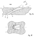
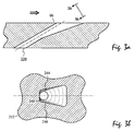
- FIGS. 2 (a), (b) show a known diffuser geometry with lateral expansion
- Figures 3 (a), (b) a known diffuser geometry with additional downstream Expansion of the film cooling hole.
- the first inner surface of the diffuser section is preferably elliptical, particularly preferably rounded in a circle.
- the specification of the curve shape refers to a section of the hole with a plane parallel to the outer surface.
- the Inner surface is the cutting edge of the inner surface with the outer surface itself be circular or elliptical.
- the radius of curvature can be along the axis of the Film cooling hole vary and then goes steadily from the curvature at the inlet of the Diffuser section over to the curvature on the outer surface.
- the first inner surface is designed so that it is in a smooth curve in the Side surfaces merges.
- the second inner surface is advantageously essentially flat and also advantageously merges into the side surfaces in a smooth curve.
- the first and second inner surfaces advantageously diverge to the outlet of the Diffuser section towards each other at an angle less than 30 °, preferred at an angle between 5 ° and 20 °. It is also advantageous if at least one of the side surfaces away from the axis of the film cooling hole at an angle greater than 5 °, preferably greater than 10 °, diverges. Diverge particularly advantageously both side surfaces at such an angle away from the axis.
- the axis each film cooling hole preferably makes an angle with the outer surface between 5 ° and 50 °, preferably between 15 ° and 40 °, particularly preferred between 25 ° and 35 °.
- each film cooling hole has one Feed section, the feed section having an inlet on the inner Surface and the outlet of the feed section, the inlet of the Diffuser section forms.
- the feed section has between its inlet and its outlet has a constant cross section, particularly preferably one constant elliptical cross section.
- the cross section of the feed section does not remain constant, but to Diffuser section through a step or a surface of another slope enlarged.
- the cooled wall forms the outer wall a hollow profile body, in particular a gas turbine blade.
- Figure 1 (a) shows a cross section through a wall 10 of a hollow profile body Gas turbine blade with a film cooling hole 20 according to the invention.
- the Film cooling hole 20 extends from the inner surface 14 to the outer Surface 12 of the wall 10. Flows in the direction of the arrow on the outer surface 12 Hot gas along.
- the inner surface 14 is a boundary surface Coolant chamber that contains pressurized chilled air.
- the film cooling hole has a cylindrical feed section 22, whose cross-section at the inlet 30 determines the amount of cooling air flowing through.
- the cooling air flows from the outlet 32 of the feed section 22 into the diffuser section 24.
- the cut edge of the first inner surface 40 is parallel to the axis 26 of the film cooling hole 20.
- the axis 26 emerges from the outer surface 12 at an angle of 30 °.
- the cut edges of the inner surfaces 40, 42 with the outer surface are designated by the reference symbols 50 and 52.
- the diffuser section further has side surfaces 44 and 46 which intersect the inner surfaces 40, 42. Both side surfaces 44, 46 diverge towards the outlet 36 of the diffuser section away from the axis 26 of the film cooling hole.
- the cooling air flow is quickly towards the Direction of flow of the hot gas is deflected so that the blown out cooling air as a protective film on the profile surface.
- the blowout rates are included small, so there is a risk that the cooling air through the flow boundary layer is small.
- the inner surface 40 is rounded in a circle toward the axis 26 of the film cooling hole 20. At the cutting edge 50, the intersection of the inner surface 40 with the outer surface 12, the radius of curvature R 2 .
- the feed section 22 is cylindrical with a constant cross section.
- the outlet 32 of the feed section coincides with the inlet 32 of the diffuser section 24 in this embodiment.
- the radius of curvature of the first inner surface 40 at the inlet 34 of the diffuser section is thus determined by the cylindrical feed section. Its value at this point is therefore d / 2 , where d denotes the diameter of the cylinder section.
- the radius of curvature of the inner surface 40 increases continuously and continuously from d / 2 to R 2 .
- the second inner surface 42 is essentially flat and merges with the side lines 44, 46 in a smooth curve with a radius of curvature R at the intersection lines.
- Figures 2 (b), 3 (b) are the first inner surfaces 140, 240 just designed. They go in the cases shown in Figures 2 (b) and 3 (b) in a smooth curve in the side surfaces 144, 146 and 244, 246 over, it remains however always a flat section of considerable size. Near edges 150 or 250, the wall thickness is particularly small (reference symbol W in FIGS. 2 (a), 3 (a)) and thus susceptible to foreign object impact. Rounding off the first Inner surface 40 in the invention the stiffness of this area becomes significant increased, since the forces generated in the impact laterally into areas with larger Wall thickness can be deflected. In addition, by rounding out the critical area of the outer surface 12, under which areas are very small Wall thickness are significantly reduced compared to the known designs.
- the edge 52 is still non-circular designed. This does not adversely affect the stability of the hole, however the wall at edge 52 has almost its maximum thickness.
- the stability of the Film cooling hole 20 of FIG. 1 thus reaches the stability of cylindrical cooling holes approach.
- the cooling properties are due to the little change Ratio of diffuser opening to supply opening a cylinder hole wide think.
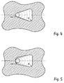
- the first inner surface 440 is elliptical rounded, i.e. the cross sections of the film cooling hole with planes parallel to the outer The surface shows an elliptical arc as the cut edge.
- FIG. 6 shows an embodiment in which the first inner surface 540 is rounded by using two basket arches with different radii R 1 , R 2 .
- Such an embodiment is particularly expedient if the axis of the film cooling holes has an additional lateral angle to the hot gas flow. In some situations it is advantageous to widen the film cooling holes laterally only to one side. Even in such a case, the use of two basket arches with a different radius is expedient for the expanded and the non-expanded side (FIG. 7).
Abstract
Description
Die Erfindung betrifft eine gekühlte Wand mit Kühlluftbohrungen, insbesondere mit Filmkühlbohrungen.The invention relates to a cooled wall with cooling air holes, in particular with film cooling holes.
Zur Steigerung der Leistung und des Wirkungsgrades werden bei heutigen Gasturbinenanlagen immer höhere Turbineneintrittstemperaturen verwendet. Um die Turbinenschaufeln vor den erhöhten Heißgastemperaturen zu schützen, müssen diese intensiv gekühlt werden. Bei entsprechend hohen Eintrittstemperaturen reicht eine rein konvektive Kühlung nicht mehr aus. Es wird daher vielfach die Methode der Filmkühlung verwendet. Dabei werden die Turbinenschaufeln durch einen Kühlfilm vor dem Heißgas geschützt. In die Schaufeln werden dazu Ausnehmungen, beispielsweise Bohrungen, eingebracht, durch die die Kühlluft ausgeblasen wird.To increase performance and efficiency, today's Gas turbine plants used ever higher turbine inlet temperatures. To the To protect turbine blades from the elevated hot gas temperatures these are cooled intensively. If the inlet temperature is high enough purely convective cooling is no longer sufficient. It is therefore often the method of Film cooling used. The turbine blades are covered by a cooling film protected from the hot gas. For this purpose, recesses are made in the blades, For example, holes are introduced through which the cooling air is blown out.
Um einen möglichst hohen Kühleffekt zu erreichen, muß die ausgeblasene Kühlluft möglichst schnell umgelenkt werden und schützend an der Profiloberfläche entlang strömen. Um auch die zwischen den Bohrungen liegenden Gebiete zu schützen, ist zudem eine schnelle seitliche Ausbreitung der Kühlluft erforderlich. Dies kann dadurch erreicht werden daß die Kühlluftbohrungen einen Diffusor aufweisen, der aufgrund der seitlichen Aufweitung eine breitere Überdeckung der Oberfläche ermöglicht. Zur weiteren Verbesserung des Mischungsverhaltens werden Diffusorgeometrien verwendet, bei denen die Bohrung nicht nur seitlich, sondern zusätzlich auf der stromabwärts liegenden Seite der Bohrung aufgeweitet wird. Die Ausblaseraten bei diesen Diffusorgeometrien sind klein, so daß die Gefahr, daß die Kühlluff durch die Strömungsgrenzschicht hindurchtritt gering ist. Daher kann der Kühlwirkungsgrad gegenüber einer zylindrischen Bohrung erheblich gesteigert werden.In order to achieve the highest possible cooling effect, the blown-out cooling air must be redirected as quickly as possible and protectively along the profile surface stream. In order to protect the areas between the wells, too rapid lateral expansion of the cooling air is also required. This can can be achieved in that the cooling air holes have a diffuser that due to the lateral expansion, a wider coverage of the surface enables. To further improve the mixing behavior Diffuser geometries are used in which the hole is not only on the side, but is additionally expanded on the downstream side of the bore. The Blowout rates with these diffuser geometries are small, so that the risk that the Cooling air passing through the flow boundary layer is low. Therefore, the Cooling efficiency significantly increased compared to a cylindrical bore become.
Eine Erodierelektrode, mit der in Tragflügeln Löcher geformt werden können, die sich in lateraler und longitudinaler Richtung aufweiten, ist aus der Druckschrift US-A-4,197,443 bekannt.An eroding electrode that can be used to make holes in wings that widen in the lateral and longitudinal direction is known from US-A-4,197,443 known.
Die Druckschrift EP-B-228 338 beschreibt eine gekühlte Wand mit einem Kühlmittelkanal, der einen Zumeßabschnitt und einen Diffusorabschnitt aufweist. Der Diffusorabschnitt enthält in stromaufwärtiger bzw. stromabwärtiger Richtung jeweils eine ebene Oberfläche. Zwei Seitenoberflächen divergieren zu dem Kühlmittelauslaß hin voneinander weg.EP-B-228 338 describes a cooled wall with a Coolant channel, which has a metering section and a diffuser section. Of the Diffuser section contains in upstream and downstream directions, respectively a flat surface. Two side surfaces diverge from that Coolant outlet away from each other.
Erfahrungsgemäß kommt es im Betrieb einer Gasturbine immer wieder zu Fehlfunktionen, die dazu führen können, daß sich Teile der Maschine lösen, durch die Turbine transportiert werden und dabei Schaden anrichten. Die Bereiche mit hoher Strömungsumlenkung sind dabei am meisten von Fremdkörperaufprall betroffen. Die Fremdkörper haben in der Regel eine größere spezifische Dichte als das die Maschine durchströmende Heißgas. Demzufolge werde die Fremdkörper an diesen Stellen weniger stark umgelenkt und prallen an eine Wand auf. Typische Aufprallstellen finden sich etwa im Bereich der Vorderkante auf der Saugseite von Turbinenschaufeln. Treffen die Fremdkörper auf solche Stellen der Schaufel auf, an denen Kühlbohrungen angebracht sind, besteht bei den bisher bekannten Diffusorgeometrien die Gefahr, daß der Lochquerschnitt reduziert oder sogar vollständig verschlossen wird. Die Kühlwirkung wird dadurch stark vermindert. Bei den heute üblichen engen Auslegungsgrenzen kann dies zu einer Überschreitung der maximal zulässigen Materialtemperaturen führen, was die Lebensdauer der Schaufel drastisch reduziert. Experience has shown that operation of a gas turbine occurs again and again Malfunctions that can cause parts of the machine to come loose the turbine is transported and cause damage. The areas with high flow deflection are mostly caused by foreign body impacts affected. The foreign bodies usually have a greater specific density than the hot gas flowing through the machine. As a result, the foreign bodies come on these places are deflected less and hit a wall. Typical Impact points can be found in the area of the front edge on the suction side of Turbine blades. Foreign objects hit such places of the blade which cooling holes are made, is in the previously known Diffuser geometries the risk that the hole cross section is reduced or even is completely closed. This greatly reduces the cooling effect. At Today's narrow design limits can lead to this being exceeded of the maximum allowable material temperatures, leading to the lifespan of Bucket drastically reduced.
Hier setzt die Erfindung an. Es soll eine gekühlte Wand geschaffen werden, die mit einer Anordnung von Kühlungsbohrungen ausgestattet ist, die bei hoher Kühleffektivität eine verbesserte Stabilität und Zuverlässigkeit aufweist. Diese Aufgabe wird durch die gekühlte Wand des unabhängigen Anspruchs 1 gelöst. Weitere vorteilhafte und zweckmäßige Ausgestaltungen ergeben sich aus den abhängigen Ansprüchen, der Beschreibung und den Zeichnungen.This is where the invention comes in. A chilled wall is to be created using an arrangement of cooling holes that is equipped with high Cooling effectiveness has improved stability and reliability. This The object is achieved by the cooled wall of independent claim 1. Further advantageous and expedient configurations result from the dependent claims, the description and the drawings.
Eine gattungsgemäße gekühlte Wand umfaßt eine äußere Oberfläche, die einem Heißgasstrom ausgesetzt wird, der in stromabwärtiger Richtung an der äußeren Oberfläche entlangströmt, eine innere Oberfläche, bevorzugt zur Bildung eines Teils einer Kühlmittelkammer zum Aufnehmen von vorzugsweise unter Druck stehendem Kühlmittel, zumindest ein Filmkühlloch innerhalb der Wand, welches einen Diffusorabschnitt und einen Auslaß an der äußeren Oberfläche aufweist. Dabei ist die Achse des Filmkühllochs so gerichtet, daß eine Kühlmittelströmung aus dem Auslaß so gerichtet wird, daß sie eine Geschwindigkeitskomponente entlang der stromabwärtigen Richtung des Heißgases hat. Der Diffusorabschnitt weist eine erste Innenfläche mit Abstand von einer zweiten Innenfläche auf, wobei die erste und zweite Innenfläche die äußere Oberfläche der Wand schneiden. Dabei bildet die Schnittkante der ersten Innenfläche mit der äußeren Oberfläche eine stromaufwärtige Kante des Auslasses und die Schnittkante der zweiten Innenfläche bildet mit der äußeren Oberfläche eine stromabwärtige Kante des Auslasses. Weiter weist der Diffusorabschnitt einander zugewandte Seitenflächen auf, die die erste und zweite Innenfläche verbinden und die zu dem Auslaß des Diffusorabschnitts hin voneinander divergieren. Erfindungsgemäß ist die erste Innenfläche des Diffusorabschnitts so gestaltet, daß sie zur Achse des Filmkühllochs hin gerundet ist.A generic cooled wall includes an outer surface that one Hot gas flow is exposed to the downstream in the outer Flows along surface, an inner surface, preferably to form a part a coolant chamber for receiving preferably pressurized Coolant, at least a film cooling hole inside the wall, which one Diffuser section and has an outlet on the outer surface. It is directed the axis of the film cooling hole so that a coolant flow from the Outlet is directed so that it has a speed component along the downstream direction of the hot gas. The diffuser section has a first Inner surface at a distance from a second inner surface, the first and second inner surface cut the outer surface of the wall. The forms Cut edge of the first inner surface with the outer surface upstream edge of the outlet and the cut edge of the second inner surface forms a downstream edge of the outlet with the outer surface. Continue the diffuser section has mutually facing side surfaces which are the first and connect the second inner surface toward the outlet of the diffuser section diverge from each other. According to the first inner surface of the Diffuser section designed so that they are rounded toward the axis of the film cooling hole is.
Figuren 2(a),(b) zeigen eine bekannte Diffusorgeometrie mit seitlicher Aufweitung, Figuren 3(a),(b) eine bekannte Diffusorgeometrie mit zusätzlicher stromabwärtiger Aufweitung des Filmkühllochs. Es wurde nun gefunden, daß solche Kühlbohrungen an der stromaufwärtigen Auslaßkante (Bezugszeichen W) besonders anfällig für Fremdkörperaufprall sind. Die Wand ist dort sehr dünn und wird durch Fremdkörperaufprall leicht nach unten gedrückt. Der Querschnitt der Kühlbohrung wird dadurch verringert, im Extremfall wird die Bohrung sogar ganz verschlossen. FIGS. 2 (a), (b) show a known diffuser geometry with lateral expansion, Figures 3 (a), (b) a known diffuser geometry with additional downstream Expansion of the film cooling hole. It has now been found that such cooling holes particularly susceptible to at the upstream outlet edge (reference symbol W) Foreign object impact. The wall is very thin there and is covered by Foreign object impact pushed down slightly. The cross section of the cooling hole is reduced, in extreme cases the hole is even completely closed.
Durch die erfindungsgemäße Ausrundung der ersten Innenfläche des Diffusorabschnitts zur Achse der Kühlbohrung hin wird die Steifigkeit der Kante deutlich erhöht, da die beim Aufprall eines Fremdkörpers entstehenden Kräfte seitlich in Gebiet größerer Wandstärke abgelenkt werden.By rounding the first inner surface of the Diffuser section towards the axis of the cooling hole becomes the rigidity of the edge significantly increased because the forces generated when a foreign object collides be deflected laterally into areas of greater wall thickness.
Die Stabilität eines solchen erfindungsgemäßen Filmkühllochs liegt zwar unter der eines zylinderförmigen Lochs, aber deutlich über der konventioneller nichtkreisförmiger Löcher. Die Kühleigenschaften liegen dagegen klar über denen zylindrischer Löcher, sie sind verglichen mit den üblichen Diffusorgeometrien (Fig. 2 und 3) praktisch nicht verringert.The stability of such a film cooling hole according to the invention is below that of a cylindrical hole, but clearly above that of the conventional one non-circular holes. The cooling properties, however, are clearly above those cylindrical holes, they are compared to the usual diffuser geometries (Fig. 2 and 3) practically not reduced.
Bevorzugt wird die erste Innenfläche des Diffusorabschnitts elliptisch, besonders bevorzugt kreisförmig gerundet. Dabei bezieht sich die Angabe der Kurvenform auf einen Schnitt des Lochs mit einer Ebene parallel zur äußeren Oberfläche. Insbesondere wird bei einer kreisförmigen bzw. elliptischen Rundung der Innenfläche also die Schnittkante der Innenfläche mit der äußeren Oberfläche selbst kreisförmig bzw. elliptisch sein. Der Krümmungsradius kann entlang der Achse des Filmkühllochs variieren und geht dann stetig von der Krümmung am Einlaß des Diffusorabschnitts zu der Krümmung an der äußeren Oberfläche über.The first inner surface of the diffuser section is preferably elliptical, particularly preferably rounded in a circle. The specification of the curve shape refers to a section of the hole with a plane parallel to the outer surface. In particular, in the case of a circular or elliptical rounding, the Inner surface is the cutting edge of the inner surface with the outer surface itself be circular or elliptical. The radius of curvature can be along the axis of the Film cooling hole vary and then goes steadily from the curvature at the inlet of the Diffuser section over to the curvature on the outer surface.
Zweckmäßig ist auch eine parabolische oder hyperbolische Ausrundung oder die Ausgestaltung der Ausrundung der Innenfläche unter Verwendung von zwei oder mehreren Korbbögen.A parabolic or hyperbolic fillet or the Design the fillet of the inner surface using two or several basket arches.
Bevorzugt ist die erste Innenfläche so gestaltet, daß sie in einer glatten Kurve in die Seitenflächen übergeht. Die zweite Innenfläche ist vorteilhaft im wesentlichen eben und geht mit Vorteil ebenfalls in einer glatten Kurve in die Seitenflächen über.Preferably, the first inner surface is designed so that it is in a smooth curve in the Side surfaces merges. The second inner surface is advantageously essentially flat and also advantageously merges into the side surfaces in a smooth curve.
Vorteilhaft divergieren die erste und zweite Innenfläche zu dem Auslaß des Diffusorabschnitts hin voneinander unter einem Winkel kleiner als 30°, bevorzugt unter einem Winkel zwischen 5° und 20°. Weiter ist es vorteilhaft, wenn wenigstens eine der Seitenflächen von der Achse des Filmkühllochs weg unter einem Winkel größer als 5°, bevorzugt größer als 10°, divergiert. Besonders vorteilhaft divergieren beide Seitenflächen unter einen solchen Winkel von der Achse weg. Die Achse jedes Filmkühllochs schließt mit der äußeren Oberfläche vorzugsweise einen Winkel zwischen 5° und 50°, bevorzugt zwischen 15° und 40°, besonders bevorzugt zwischen 25° und 35° ein.The first and second inner surfaces advantageously diverge to the outlet of the Diffuser section towards each other at an angle less than 30 °, preferred at an angle between 5 ° and 20 °. It is also advantageous if at least one of the side surfaces away from the axis of the film cooling hole at an angle greater than 5 °, preferably greater than 10 °, diverges. Diverge particularly advantageously both side surfaces at such an angle away from the axis. The axis each film cooling hole preferably makes an angle with the outer surface between 5 ° and 50 °, preferably between 15 ° and 40 °, particularly preferred between 25 ° and 35 °.
In einer weiteren Ausgestaltung der Erfindung weist jedes Filmkühlloch einen Zuführabschnitt auf, wobei der Zuführabschnitt einen Einlaß an der inneren Oberfläche aufweist und der Auslaß des Zuführabschnitts den Einlaß des Diffusorabschnitts bildet. Bevorzugt hat der Zuführabschnitt zwischen seinem Einlaß und seinem Auslaß eine konstanten Querschnitt, besonders bevorzugt einen konstanten elliptischen Querschnitt. Es liegt jedoch auch im Rahmen der Erfindung, daß der Querschnitt des Zuführabschnitts nicht konstant bleibt, sondern sich zum Diffusorabschnitt hin etwa durch eine Stufe oder eine Fläche anderer Steigung vergrößert.In a further embodiment of the invention, each film cooling hole has one Feed section, the feed section having an inlet on the inner Surface and the outlet of the feed section, the inlet of the Diffuser section forms. Preferably, the feed section has between its inlet and its outlet has a constant cross section, particularly preferably one constant elliptical cross section. However, it is also within the scope of the invention that the cross section of the feed section does not remain constant, but to Diffuser section through a step or a surface of another slope enlarged.
In einer Ausgestaltung der Erfindung bildet die gekühlte Wand die äußere Wand eines Hohlprofilkörpers, insbesondere einer Gasturbinenschaufel.In one embodiment of the invention, the cooled wall forms the outer wall a hollow profile body, in particular a gas turbine blade.
Die Erfindung soll nachfolgend anhand von Ausführungsbeispielen im Zusammenhang mit den Zeichnungen näher erläutert werden. Es zeigen
- Fig. 1a
- einen Querschnitt durch eine gekühlte Wand mit einem erfindungsgemäßen Filmkühlloch;
- Fig. 1b
- eine Teilansicht der gekühlten Wand in
Richtung 1b-1b von Fig. 1a; - Fig. 2a
- einen Querschnitt durch eine gekühlte Wand mit einem Filmkühlloch mit seitlicher Aufweitung nach dem Stand der Technik;
- Fig. 2b
- eine Teilansicht der gekühlten Wand in
Richtung 2b-2b von Fig. 2a; - Fig. 3a
- einen Querschnitt durch eine gekühlte Wand mit einem Filmkühlloch mit seitlicher und stromabwärtiger Aufweitung nach dem Stand der Technik;
- Fig. 3b
- eine Teilansicht der gekühlten Wand in
Richtung 3b-3b von Fig. 3a; - Fig. 4-7
- jeweils eine Ansicht wie Fig. 1b, entsprechend weiteren Ausführungsbeispielen der Erfindung;
- Fig. 1a
- a cross section through a cooled wall with a film cooling hole according to the invention;
- Fig. 1b
- a partial view of the cooled wall in the
direction 1b-1b of Fig. 1a; - Fig. 2a
- a cross section through a cooled wall with a film cooling hole with lateral expansion according to the prior art;
- Fig. 2b
- a partial view of the cooled wall in the
direction 2b-2b of Fig. 2a; - Fig. 3a
- a cross section through a cooled wall with a film cooling hole with lateral and downstream expansion according to the prior art;
- Fig. 3b
- a partial view of the cooled wall in the
direction 3b-3b of Fig. 3a; - Fig. 4-7
- in each case a view like FIG. 1b, corresponding to further exemplary embodiments of the invention;
Es sind nur die für das Verständnis der Erfindung wesentlichen Elemente gezeigt. Nicht gezeigt ist beispielsweise der vollständige Hohlprofilkörper und gesamte Anordnung der Kühlbohrungen. Die Strömungsrichtung des Arbeitsmittels ist mit Pfeilen bezeichnet.Only the elements essential for understanding the invention are shown. For example, the complete hollow profile body and the whole are not shown Arrangement of the cooling holes. The direction of flow of the working fluid is with Arrows.
Figur 1(a) zeigt einen Querschnitt durch eine Wand 10 eines Hohlprofilkörpers einer
Gasturbinenschaufel mit einem Filmkühlloch 20 nach der Erfindung. Das
Filmkühlloch 20 erstreckt sich von der inneren Oberfläche 14 zur äußeren
Oberfläche 12 der Wand 10. An der äußeren Oberfläche 12 strömt in Pfeilrichtung
Heißgas entlang. Die innere Oberfläche 14 ist Begrenzungsfläche einer
Kühlmittelkammer, die unter Druck stehende Kühllutt enthält. Auf der
Kühlkammerseite weist das Filmkühlloch einen zylindrischen Zuführabschnitt 22 auf,
dessen Querschnitt am Einlaß 30 die durchströmende Kühlluftmenge bestimmt.Figure 1 (a) shows a cross section through a
Vom Auslaß 32 des Zuführabschnitts 22 strömt die Kühlluft in den Diffusorabschnitt
24. Der Diffusorabschnitt 24 weist zwei voneinander beanstandete Innenflächen 40,
42 auf, die im Ausführungsbeispiel von Fig. 1a voneinander unter einem Winkel von
β = 10° divergieren. In der Seitenansicht von Fig. 1(a) ist die Schnittkante der ersten
Innenfläche 40 parallel zur Achse 26 des Filmkühllochs 20. Die Achse 26 tritt in
diesem Ausführungsbeispiel unter einem Winkel von 30° an der äußeren Oberfläche
12 aus. Die Innenflächen 40,42 bilden somit mit der äußeren Oberfläche 12 die
Winkel γ1 = 30° bzw. γ2= 20° Die Schnittkanten der Innenflächen 40,42 mit der
äußeren Oberfläche sind mit den Bezugszeichen 50 bzw. 52 bezeichnet. Wie in Fig.
1b zu sehen, weist der Diffusorabschnitt weiter Seitenflächen 44 und 46 auf, die die
Innenflächen 40, 42 schneiden. Beide Seitenflächen 44,46 divergieren zu dem
Auslaß 36 des Diffusorabschnitts hin von der Achse 26 des Filmkühllochs weg. The cooling air flows from the outlet 32 of the
Dadurch wird eine seitliche Ausbreitung der Kühlluft erreicht, wodurch auf der
äußeren Oberfläche 12 auch zwischen den einzelnen Filmkühllöchern 20 ein
schützender Kühlluftfilm bereitgestellt wird.As a result, the cooling air is spread laterally, which means that
Durch den Diffusor wird der Kühlluftstrom schnell in Richtung auf die Strömungsrichtung des Heißgases umgelenkt, so daß sich die ausgeblasen Kühlluft als schützender Film an die Profiloberfläche anlegt. Die Ausblaseraten sind dabei klein, so daß die Gefahr, daß die Kühlluft durch die Strömungsgrenzschicht hindurchtritt gering ist.Through the diffuser, the cooling air flow is quickly towards the Direction of flow of the hot gas is deflected so that the blown out cooling air as a protective film on the profile surface. The blowout rates are included small, so there is a risk that the cooling air through the flow boundary layer is small.
Die Innenfläche 40 ist kreisförmig zur Achse 26 des Filmkühllochs 20 hin gerundet.
An der Schnittkante 50, dem Schnitt der Innenfläche 40 mit der äußeren Oberfläche
12 beträgt der Krümmungsradius R2 . Der Zuführabschnitt 22 ist in diesem
Ausführungsbeispiel zylindrisch mit konstantem Querschnitt ausgestaltet. Der
Auslaß 32 des Zuführabschnitts fällt in diesem Ausführungsbeispiel mit dem Einlaß
32 des Diffusorabschnitts 24 zusammen. Der Krümmungsradius der ersten
Innenfläche 40 am Einlaß 34 des Diffusorabschnitts ist also durch den zylindrischen
Zuführabschnitt bestimmt. Sein Wert beträgt an dieser Stelle somit d/2, wobei d den
Durchmesser des Zylinderabschnitts bezeichnet. Zwischen dem Einlaß 34 und
Auslaß 36 des Diffusorabschnitts steigt der Krümmungsradius der Innenfläche 40
stetig und kontinuierlich von d/2 auf R2 . Die zweite Innenfläche 42 ist im
wesentlichen eben und geht an den Schnittlinien mit den Seitenflächen 44,46 in
einer glatten Kurve mit Krümmungsradius R in diese über.The
In bekannten Lösungen (Figuren 2(b), 3(b)) sind die ersten Innenflächen 140, 240
eben ausgestaltet. Sie gehen in den in Figuren 2(b) und 3(b) gezeigten Fällen zwar
in einer glatten Kurve in die Seitenflächen 144, 146 bzw. 244, 246 über, es verbleibt
jedoch stets ein ebenes Teilstück beträchtlicher Größe. In der Nähe der Kanten 150
bzw. 250 ist die Wandstärke besonders gering (Bezugszeichen W in Figuren 2(a),
3(a)) und damit anfällig gegen Fremdkörperaufprall. Durch die Abrundung der ersten
Innenfläche 40 in der Erfindung wird die Steifigkeit dieses Bereichs signifikant
erhöht, da die beim Aufprall entstehende Kräfte seitlich in Bereiche mit größerer
Wandstärke abgelenkt werden. Darüber hinaus wird durch die Ausrundung der
kritische Bereich der äußeren Oberfläche 12, unter der sich Bereiche sehr geringer
Wandstärke befinden, im Vergleich zu den bekannten Designs deutlich verkleinert. In known solutions (Figures 2 (b), 3 (b)) are the first
Zur Erzielung maximaler Kühleffektivität ist die Kante 52 weiterhin nicht-kreisförmig
gestaltet. Dies wirkt sich auf die Stabilität des Lochs jedoch nicht nachteilig aus, da
die Wand an der Kante 52 nahezu ihre maximale Dicke aufweist. Die Stabilität des
Filmkühllochs 20 von Fig. 1 reicht somit an die Stabilität zylinderformiger Kühllöcher
heran. Die Kühleigenschaften sind jedoch wegen des kaum veränderten
Verhältnisses von Diffusoröffnung zu Zuführöffnung einem Zylinderloch weit
überlegen.In order to achieve maximum cooling effectiveness, the
Wählt man für den Radius R2 den geringstmöglichen Wert, R2 = d/2, so ist der
Krümmungsradius der ersten Innenfläche 340 entlang der Achse des Filmkühllochs
konstant (Fig. 4). Die Stabilität eines solchen Filmkühllochs entspricht praktisch der
eines Zylinderlochs mit Durchmesser d, es weist jedoch weit überlegene
Kühleigenschaften auf.If the smallest possible value is selected for the radius R 2 , R 2 = d / 2, the radius of curvature of the first
In einer weiteren Ausführungsform (Fig. 5) ist die erste Innenfläche 440 elliptisch
gerundet, d.h. die Querschnitte des Filmkühllochs mit Ebenen parallel zur äußeren
Oberfläche zeigen als Schnittkante je einen Ellipsenbogen. Obwohl in geringerem
Ausmaß als bei einer kreisförmigen Ausrundung führt auch diese Ausgestaltung zu
einer merklichen Erhöhung der Stabilität. Auch die Verwendung andere
Kegelschnitte, etwa von parabolischen oder hyperbolischen Ausrundung führen zu
einer erhöhten Stabilität.In a further embodiment (FIG. 5), the first
In Fig. 6 ist eine Ausführungsform gezeigt, in der die erste Innenfläche 540 durch Verwendung von zwei Korbbögen mit verschiedenen Radien R1, R2 gerundet ist. Eine solche Ausführungsform ist insbesondere dann zweckmäßig, wenn die Achse der Filmkühllöcher einen zusätzlichen lateralen Winkel zur Heißgasströmung aufweist. In manchen Situationen ist es vorteilhaft, die Filmkühllöcher nur nach einer Seite hin seitlich aufzuweiten. Auch in einem solchen Fall ist die Verwendung von zwei Korbbögen mit unterschiedlichem Radius für die aufgeweitete und die nicht aufgeweitete Seite zweckmäßig (Fig. 7). 6 shows an embodiment in which the first inner surface 540 is rounded by using two basket arches with different radii R 1 , R 2 . Such an embodiment is particularly expedient if the axis of the film cooling holes has an additional lateral angle to the hot gas flow. In some situations it is advantageous to widen the film cooling holes laterally only to one side. Even in such a case, the use of two basket arches with a different radius is expedient for the expanded and the non-expanded side (FIG. 7).
- 1010th
- gekühlte Wandchilled wall
- 12,112,21212,112,212
- äußere Oberflächeouter surface
- 1414
- innere Oberflächeinner surface
- 20,120,22020,120,220
- FilmkühllochFilm cooling hole
- 2222
- ZuführabschnittFeed section
- 2424th
- DiffusorabschnittDiffuser section
- 2626
- Achse des FilmkühllochsAxis of the film cooling hole
- 3030th
- Einlaß des ZuführabschnittsInlet of the feed section
- 3232
- Auslaß des ZuführabschnittsOutlet of the feed section
- 3434
- Einlaß des DiffusorabschnittsInlet of the diffuser section
- 3636
- Auslaß des DiffusorabschnittsOutlet of the diffuser section
- 40,140,240,40,140,240.
- 340,440,540340,440,540
- erste Innenfläche des Diffusorabschnittsfirst inner surface of the diffuser section
- 4242
- zweite Innenfläche des Diffusorabschnittssecond inner surface of the diffuser section
- 44,144,24444,144,244
- Seitenfläche des DiffusorabschnittsSide surface of the diffuser section
- 46,146,24646,146,246
- Seitenfläche des DiffusorabschnittsSide surface of the diffuser section
- 5050
- stromaufwärtige Schnittkanteupstream cutting edge
- 5252
- stromabwärtige Schnittkantedownstream cutting edge
Claims (12)
und einer inneren Oberfläche (14),
zumindest einem Filmkühlloch (20) innerhalb der Wand, welches einen Diffusorabschnitt (24) und einen Auslaß (36) an der äußeren Oberfläche (12) aufweist,
wobei die Achse (26) des Filmkühllochs (20) so gerichtet ist, daß eine Kühlmittelströmung aus dem Auslaß (36) so gerichtet wird, daß sie eine Geschwindigkeitskomponente entlang der stromabwärtigen Richtung hat,
wobei der Diffusorabschnitt (24) eine erste Innenfläche (40) mit Abstand von einer zweiten Innenfläche (42) aufweist, wobei die erste und zweite Innenfläche (40,42) die äußere Oberfläche (12) der Wand (10) schneiden, und die Schnittkante der ersten Innenfläche (40) mit der äußeren Oberfläche (12) eine stromaufwärtige Kante (50) des Auslasses (36) bildet und die Schnittkante der zweiten Innenfläche (42) mit der äußeren Oberfläche (12) eine stromabwärtige Kante (52) des Auslasses (36) bildet,
wobei der Diffusorabschnitt (24) Seitenflächen (44,46) aufweist, die einander zugewandt sind, die die erste und zweite Innenfläche (40,42) verbinden und die zu dem Auslaß (36) des Diffusorabschnitts hin voneinander divergieren,
dadurch gekennzeichnet, daß
die erste Innenfläche (40) des Diffusorabschnitts (24) zur Achse (26) des Filmkühllochs (20) hin gerundet ist.Cooled wall (10) having an outer surface (12) which is exposed to a hot gas flow which flows in a downstream direction along the outer surface (12),
and an inner surface (14),
at least one film cooling hole (20) within the wall, which has a diffuser section (24) and an outlet (36) on the outer surface (12),
the axis (26) of the film cooling hole (20) being directed to direct coolant flow from the outlet (36) to have a velocity component along the downstream direction,
wherein the diffuser portion (24) has a first inner surface (40) spaced from a second inner surface (42), the first and second inner surfaces (40, 42) intersecting the outer surface (12) of the wall (10) and the cut edge the first inner surface (40) with the outer surface (12) forms an upstream edge (50) of the outlet (36) and the cutting edge of the second inner surface (42) with the outer surface (12) forms a downstream edge (52) of the outlet (36) 36) forms
the diffuser section (24) having side surfaces (44, 46) which face one another, which connect the first and second inner surfaces (40, 42) and which diverge from one another towards the outlet (36) of the diffuser section,
characterized in that
the first inner surface (40) of the diffuser section (24) is rounded towards the axis (26) of the film cooling hole (20).
die erste Innenfläche (40) elliptisch, insbesondere kreisförmig gerundet ist. A cooled wall according to claim 1, wherein
the first inner surface (40) is elliptically, in particular circularly rounded.
die erste Innenfläche (40) parabolisch gerundet ist.A cooled wall according to claim 1, wherein
the first inner surface (40) is rounded parabolically.
die erste Innenfläche (40) in Form von zumindest zwei Korbbögen gerundet ist.A cooled wall according to claim 1, wherein
the first inner surface (40) is rounded in the form of at least two basket arches.
die erste Innenfläche (40) in einer glatten Kurve in die Seitenflächen (44,46) übergeht.Cooled wall according to one of the preceding claims, in which
the first inner surface (40) merges into the side surfaces (44, 46) in a smooth curve.
die zweite Innenfläche (42) im wesentlichen eben ist und/oder in einer glatten Kurve in die Seitenflächen (44,46) übergeht.Cooled wall according to one of the preceding claims, in which
the second inner surface (42) is essentially flat and / or merges into the side surfaces (44, 46) in a smooth curve.
die erste und zweite Innenfläche (40, 42) zu dem Auslaß (36) des Diffusorabschnitts (24) hin unter einem Winkel kleiner als 30° voneinander divergieren, bevorzugt unter einem Winkel zwischen 5° und 20°.Cooled wall according to one of the preceding claims, in which
the first and second inner surfaces (40, 42) diverge from one another towards the outlet (36) of the diffuser section (24) at an angle of less than 30 °, preferably at an angle between 5 ° and 20 °.
wenigstens eine, bevorzugt beide der Seitenflächen (44,46) von der Achse (26) des Filmkühllochs (20) weg unter einem Winkel größer als 5°, bevorzugt größer als 10°, divergieren.Cooled wall according to one of the preceding claims, in which
at least one, preferably both, of the side surfaces (44, 46) from the axis (26) of the film cooling hole (20) diverge at an angle greater than 5 °, preferably greater than 10 °.
die Achse (26) jedes Filmkühllochs (20) mit der äußeren Oberfläche (12) einen Winkel zwischen 5° und 50°, bevorzugt zwischen 15° und 40°, besonders bevorzugt zwischen 25° und 35° einschließt.Cooled wall according to one of the preceding claims, in which
the axis (26) of each film cooling hole (20) with the outer surface (12) forms an angle between 5 ° and 50 °, preferably between 15 ° and 40 °, particularly preferably between 25 ° and 35 °.
jedes Filmkühlloch (20) einen Zuführabschnitt (22) aufweist, wobei der Zuführabschnitt (22) einen Einlaß (30) an der inneren Oberfläche (14) aufweist und der Auslaß (32) des Zuführabschnitts (22) den Einlaß (34) des Diffusorabschnitts (24) bildet.Cooled wall according to one of the preceding claims, in which
each film cooling hole (20) has a feed section (22), the feed section (22) having an inlet (30) on the inner surface (14) and the outlet (32) of the feed section (22) the inlet (34) of the diffuser section ( 24) forms.
der Zuführabschnitt (22) zwischen seinem Einlaß (30) und seinem Auslaß (32) konstanten Querschnitt aufweist, bevorzugt konstanten elliptischen Querschnitt aufweist.A cooled wall according to claim 10, wherein
the feed section (22) has a constant cross section between its inlet (30) and its outlet (32), preferably has a constant elliptical cross section.
die Wand (10) die äußere Wand eines Hohlprofilkörpers, insbesondere einer Gasturbinenschaufel ist.Cooled wall according to one of the preceding claims, in which
the wall (10) is the outer wall of a hollow profile body, in particular a gas turbine blade.
Priority Applications (3)
| Application Number | Priority Date | Filing Date | Title |
|---|---|---|---|
| DE59808269T DE59808269D1 (en) | 1998-03-23 | 1998-03-23 | Film cooling hole |
| EP98810253A EP0945593B1 (en) | 1998-03-23 | 1998-03-23 | Film-cooling hole |
| US09/271,267 US6183199B1 (en) | 1998-03-23 | 1999-03-17 | Cooling-air bore |
Applications Claiming Priority (1)
| Application Number | Priority Date | Filing Date | Title |
|---|---|---|---|
| EP98810253A EP0945593B1 (en) | 1998-03-23 | 1998-03-23 | Film-cooling hole |
Publications (2)
| Publication Number | Publication Date |
|---|---|
| EP0945593A1 true EP0945593A1 (en) | 1999-09-29 |
| EP0945593B1 EP0945593B1 (en) | 2003-05-07 |
Family
ID=8236008
Family Applications (1)
| Application Number | Title | Priority Date | Filing Date |
|---|---|---|---|
| EP98810253A Expired - Lifetime EP0945593B1 (en) | 1998-03-23 | 1998-03-23 | Film-cooling hole |
Country Status (3)
| Country | Link |
|---|---|
| US (1) | US6183199B1 (en) |
| EP (1) | EP0945593B1 (en) |
| DE (1) | DE59808269D1 (en) |
Cited By (8)
| Publication number | Priority date | Publication date | Assignee | Title |
|---|---|---|---|---|
| EP1645721A3 (en) * | 2004-10-04 | 2009-10-07 | ALSTOM Technology Ltd | Gas turbine airfoil with leading edge cooling |
| EP1517003A3 (en) * | 2003-09-17 | 2012-07-11 | General Electric Company | Cooled turbomachine blade |
| EP1898051A3 (en) * | 2006-08-25 | 2013-05-15 | Alstom Technology Ltd | Gas turbine airfoil with leading edge cooling |
| EP3015648A1 (en) * | 2014-10-30 | 2016-05-04 | Rolls-Royce plc | Cooled component |
| EP3061911A1 (en) * | 2015-02-24 | 2016-08-31 | General Electric Company | Engine component |
| WO2017162743A1 (en) * | 2016-03-23 | 2017-09-28 | Siemens Aktiengesellschaft | Film cooling hole in gas turbine components |
| EP3450682A1 (en) | 2017-08-30 | 2019-03-06 | Siemens Aktiengesellschaft | Wall of a hot gas component and corresponding hot gas component |
| DE102018108729A1 (en) | 2018-04-12 | 2019-10-17 | Karlsruher Institut für Technologie | Flow guide, flow-leading component of an internal combustion engine and a turbine blade |
Families Citing this family (84)
| Publication number | Priority date | Publication date | Assignee | Title |
|---|---|---|---|---|
| US6383602B1 (en) * | 1996-12-23 | 2002-05-07 | General Electric Company | Method for improving the cooling effectiveness of a gaseous coolant stream which flows through a substrate, and related articles of manufacture |
| US6428172B1 (en) * | 1999-11-24 | 2002-08-06 | Donnelly Corporation | Rearview mirror assembly with utility functions |
| US6368060B1 (en) * | 2000-05-23 | 2002-04-09 | General Electric Company | Shaped cooling hole for an airfoil |
| US6672829B1 (en) | 2002-07-16 | 2004-01-06 | General Electric Company | Turbine blade having angled squealer tip |
| US6918742B2 (en) * | 2002-09-05 | 2005-07-19 | Siemens Westinghouse Power Corporation | Combustion turbine with airfoil having multi-section diffusion cooling holes and methods of making same |
| US6994514B2 (en) * | 2002-11-20 | 2006-02-07 | Mitsubishi Heavy Industries, Ltd. | Turbine blade and gas turbine |
| US7041933B2 (en) * | 2003-04-14 | 2006-05-09 | Meyer Tool, Inc. | Complex hole shaping |
| US20060073015A1 (en) * | 2004-10-01 | 2006-04-06 | Alstom Technology Ltd. | Gas turbine airfoil film cooling hole |
| US7246992B2 (en) | 2005-01-28 | 2007-07-24 | General Electric Company | High efficiency fan cooling holes for turbine airfoil |
| DE102005015153B4 (en) * | 2005-03-31 | 2017-03-09 | General Electric Technology Gmbh | Method for repairing or renewing cooling holes of a coated component and coated component with cooling holes of a gas turbine |
| EP1712739A1 (en) * | 2005-04-12 | 2006-10-18 | Siemens Aktiengesellschaft | Component with film cooling hole |
| FR2895691A1 (en) * | 2006-01-12 | 2007-07-06 | Snecma Sa | Turbomachine blade wall`s cooling channel forming method, involves piercing wall to make hole by using laser, and forming indentation in wall to form diffusion portion by using electro-erosion electrode |
| JP4931507B2 (en) * | 2005-07-26 | 2012-05-16 | スネクマ | Cooling flow path formed in the wall |
| FR2896710B1 (en) * | 2006-01-27 | 2009-10-30 | Snecma Sa | PROCESS FOR MANUFACTURING TURBOMACHINE COMPONENT WITH COOLING AIR EXHAUST ORIFICES |
| US7563073B1 (en) | 2006-10-10 | 2009-07-21 | Florida Turbine Technologies, Inc. | Turbine blade with film cooling slot |
| US7887294B1 (en) | 2006-10-13 | 2011-02-15 | Florida Turbine Technologies, Inc. | Turbine airfoil with continuous curved diffusion film holes |
| US7704047B2 (en) * | 2006-11-21 | 2010-04-27 | Siemens Energy, Inc. | Cooling of turbine blade suction tip rail |
| US20080271457A1 (en) * | 2007-05-01 | 2008-11-06 | General Electric Company | Cooling Holes For Gas Turbine Combustor Having A Non-Uniform Diameter Therethrough |
| US8066484B1 (en) | 2007-11-19 | 2011-11-29 | Florida Turbine Technologies, Inc. | Film cooling hole for a turbine airfoil |
| FR2926481B1 (en) * | 2008-01-23 | 2011-09-23 | Snecma | COOLING CHANNEL CLEANING IN A WALL |
| US8105030B2 (en) * | 2008-08-14 | 2012-01-31 | United Technologies Corporation | Cooled airfoils and gas turbine engine systems involving such airfoils |
| US8079810B2 (en) * | 2008-09-16 | 2011-12-20 | Siemens Energy, Inc. | Turbine airfoil cooling system with divergent film cooling hole |
| US8092176B2 (en) | 2008-09-16 | 2012-01-10 | Siemens Energy, Inc. | Turbine airfoil cooling system with curved diffusion film cooling hole |
| US8328517B2 (en) * | 2008-09-16 | 2012-12-11 | Siemens Energy, Inc. | Turbine airfoil cooling system with diffusion film cooling hole |
| US8092177B2 (en) * | 2008-09-16 | 2012-01-10 | Siemens Energy, Inc. | Turbine airfoil cooling system with diffusion film cooling hole having flow restriction rib |
| US8057179B1 (en) | 2008-10-16 | 2011-11-15 | Florida Turbine Technologies, Inc. | Film cooling hole for turbine airfoil |
| US8057180B1 (en) | 2008-11-07 | 2011-11-15 | Florida Turbine Technologies, Inc. | Shaped film cooling hole for turbine airfoil |
| US8057181B1 (en) | 2008-11-07 | 2011-11-15 | Florida Turbine Technologies, Inc. | Multiple expansion film cooling hole for turbine airfoil |
| US8245519B1 (en) | 2008-11-25 | 2012-08-21 | Florida Turbine Technologies, Inc. | Laser shaped film cooling hole |
| US8092178B2 (en) * | 2008-11-28 | 2012-01-10 | Pratt & Whitney Canada Corp. | Turbine blade for a gas turbine engine |
| US8167536B2 (en) * | 2009-03-04 | 2012-05-01 | Siemens Energy, Inc. | Turbine blade leading edge tip cooling system |
| EP2230383A1 (en) * | 2009-03-18 | 2010-09-22 | Alstom Technology Ltd | Blade for a gas turbine with cooled tip cap |
| GB0912796D0 (en) * | 2009-07-23 | 2009-08-26 | Cummins Turbo Tech Ltd | Compressor,turbine and turbocharger |
| US8742279B2 (en) * | 2010-02-01 | 2014-06-03 | United Technologies Corporation | Method of creating an airfoil trench and a plurality of cooling holes within the trench |
| US8672613B2 (en) | 2010-08-31 | 2014-03-18 | General Electric Company | Components with conformal curved film holes and methods of manufacture |
| RU2473813C1 (en) * | 2011-07-29 | 2013-01-27 | Открытое акционерное общество "Научно-производственное объединение "Сатурн" (ОАО "НПО "Сатурн") | Nozzle diaphragm of turbine with convective-film cooling |
| JP5536001B2 (en) * | 2011-09-20 | 2014-07-02 | 株式会社日立製作所 | Gas turbine blade film cooling hole setting method and gas turbine blade |
| JP2013167205A (en) * | 2012-02-15 | 2013-08-29 | Hitachi Ltd | Gas turbine blade, and tool for electrical discharge machining and machining method of the same |
| US8733111B2 (en) | 2012-02-15 | 2014-05-27 | United Technologies Corporation | Cooling hole with asymmetric diffuser |
| US8689568B2 (en) | 2012-02-15 | 2014-04-08 | United Technologies Corporation | Cooling hole with thermo-mechanical fatigue resistance |
| US8763402B2 (en) | 2012-02-15 | 2014-07-01 | United Technologies Corporation | Multi-lobed cooling hole and method of manufacture |
| US8522558B1 (en) | 2012-02-15 | 2013-09-03 | United Technologies Corporation | Multi-lobed cooling hole array |
| US10422230B2 (en) | 2012-02-15 | 2019-09-24 | United Technologies Corporation | Cooling hole with curved metering section |
| US9273560B2 (en) | 2012-02-15 | 2016-03-01 | United Technologies Corporation | Gas turbine engine component with multi-lobed cooling hole |
| US9024226B2 (en) | 2012-02-15 | 2015-05-05 | United Technologies Corporation | EDM method for multi-lobed cooling hole |
| US9284844B2 (en) | 2012-02-15 | 2016-03-15 | United Technologies Corporation | Gas turbine engine component with cusped cooling hole |
| US8683814B2 (en) | 2012-02-15 | 2014-04-01 | United Technologies Corporation | Gas turbine engine component with impingement and lobed cooling hole |
| US9410435B2 (en) | 2012-02-15 | 2016-08-09 | United Technologies Corporation | Gas turbine engine component with diffusive cooling hole |
| US9279330B2 (en) | 2012-02-15 | 2016-03-08 | United Technologies Corporation | Gas turbine engine component with converging/diverging cooling passage |
| US9416971B2 (en) | 2012-02-15 | 2016-08-16 | United Technologies Corporation | Multiple diffusing cooling hole |
| US8584470B2 (en) | 2012-02-15 | 2013-11-19 | United Technologies Corporation | Tri-lobed cooling hole and method of manufacture |
| US8683813B2 (en) | 2012-02-15 | 2014-04-01 | United Technologies Corporation | Multi-lobed cooling hole and method of manufacture |
| US9416665B2 (en) | 2012-02-15 | 2016-08-16 | United Technologies Corporation | Cooling hole with enhanced flow attachment |
| US9482100B2 (en) | 2012-02-15 | 2016-11-01 | United Technologies Corporation | Multi-lobed cooling hole |
| US8572983B2 (en) | 2012-02-15 | 2013-11-05 | United Technologies Corporation | Gas turbine engine component with impingement and diffusive cooling |
| US9422815B2 (en) | 2012-02-15 | 2016-08-23 | United Technologies Corporation | Gas turbine engine component with compound cusp cooling configuration |
| US9598979B2 (en) | 2012-02-15 | 2017-03-21 | United Technologies Corporation | Manufacturing methods for multi-lobed cooling holes |
| US8850828B2 (en) | 2012-02-15 | 2014-10-07 | United Technologies Corporation | Cooling hole with curved metering section |
| US8707713B2 (en) | 2012-02-15 | 2014-04-29 | United Technologies Corporation | Cooling hole with crenellation features |
| US9650900B2 (en) | 2012-05-07 | 2017-05-16 | Honeywell International Inc. | Gas turbine engine components with film cooling holes having cylindrical to multi-lobe configurations |
| US20130315710A1 (en) * | 2012-05-22 | 2013-11-28 | Honeywell International Inc. | Gas turbine engine components with cooling hole trenches |
| WO2013188645A2 (en) | 2012-06-13 | 2013-12-19 | General Electric Company | Gas turbine engine wall |
| US10113433B2 (en) | 2012-10-04 | 2018-10-30 | Honeywell International Inc. | Gas turbine engine components with lateral and forward sweep film cooling holes |
| US9309771B2 (en) * | 2012-10-25 | 2016-04-12 | United Technologies Corporation | Film cooling channel array with multiple metering portions |
| WO2014137470A1 (en) | 2013-03-05 | 2014-09-12 | Vandervaart Peter L | Gas turbine engine component arrangement |
| US9874110B2 (en) | 2013-03-07 | 2018-01-23 | Rolls-Royce North American Technologies Inc. | Cooled gas turbine engine component |
| WO2015065587A1 (en) | 2013-11-04 | 2015-05-07 | United Technologies Corporation | Coated cooling passage |
| US10041356B2 (en) * | 2014-08-15 | 2018-08-07 | United Technologies Corporation | Showerhead hole scheme apparatus and system |
| CN104234756B (en) * | 2014-09-15 | 2016-08-24 | 西北工业大学 | A kind of transonic speed type film cooling holes |
| US20160090843A1 (en) * | 2014-09-30 | 2016-03-31 | General Electric Company | Turbine components with stepped apertures |
| EP3034803A1 (en) | 2014-12-16 | 2016-06-22 | Rolls-Royce Corporation | Hanger system for a turbine engine component |
| US10400607B2 (en) | 2014-12-30 | 2019-09-03 | United Technologies Corporation | Large-footprint turbine cooling hole |
| US20160298462A1 (en) * | 2015-04-09 | 2016-10-13 | United Technologies Corporation | Cooling passages for a gas turbine engine component |
| US10208602B2 (en) * | 2015-04-27 | 2019-02-19 | United Technologies Corporation | Asymmetric diffuser opening for film cooling holes |
| CA2933884A1 (en) * | 2015-06-30 | 2016-12-30 | Rolls-Royce Corporation | Combustor tile |
| US20170298743A1 (en) * | 2016-04-14 | 2017-10-19 | General Electric Company | Component for a turbine engine with a film-hole |
| US10458251B2 (en) * | 2016-04-15 | 2019-10-29 | General Electric Company | Airfoil cooling using non-line of sight holes |
| US11021965B2 (en) | 2016-05-19 | 2021-06-01 | Honeywell International Inc. | Engine components with cooling holes having tailored metering and diffuser portions |
| US10605092B2 (en) | 2016-07-11 | 2020-03-31 | United Technologies Corporation | Cooling hole with shaped meter |
| US10443401B2 (en) * | 2016-09-02 | 2019-10-15 | United Technologies Corporation | Cooled turbine vane with alternately orientated film cooling hole rows |
| US10760431B2 (en) * | 2017-09-07 | 2020-09-01 | General Electric Company | Component for a turbine engine with a cooling hole |
| US10539026B2 (en) | 2017-09-21 | 2020-01-21 | United Technologies Corporation | Gas turbine engine component with cooling holes having variable roughness |
| US11359494B2 (en) * | 2019-08-06 | 2022-06-14 | General Electric Company | Engine component with cooling hole |
| CN116085117A (en) * | 2023-04-10 | 2023-05-09 | 清华大学 | Guiding structure |
Citations (6)
| Publication number | Priority date | Publication date | Assignee | Title |
|---|---|---|---|---|
| US3457619A (en) * | 1967-11-28 | 1969-07-29 | Gen Electric | Production of perforated metallic bodies |
| US4197443A (en) | 1977-09-19 | 1980-04-08 | General Electric Company | Method and apparatus for forming diffused cooling holes in an airfoil |
| EP0228338B1 (en) | 1985-12-23 | 1992-01-29 | United Technologies Corporation | Improved film cooling passages with curved corners |
| US5261789A (en) * | 1992-08-25 | 1993-11-16 | General Electric Company | Tip cooled blade |
| US5271715A (en) * | 1992-12-21 | 1993-12-21 | United Technologies Corporation | Cooled turbine blade |
| US5382133A (en) * | 1993-10-15 | 1995-01-17 | United Technologies Corporation | High coverage shaped diffuser film hole for thin walls |
Family Cites Families (5)
| Publication number | Priority date | Publication date | Assignee | Title |
|---|---|---|---|---|
| US4606701A (en) * | 1981-09-02 | 1986-08-19 | Westinghouse Electric Corp. | Tip structure for a cooled turbine rotor blade |
| US4705455A (en) * | 1985-12-23 | 1987-11-10 | United Technologies Corporation | Convergent-divergent film coolant passage |
| US5183385A (en) * | 1990-11-19 | 1993-02-02 | General Electric Company | Turbine blade squealer tip having air cooling holes contiguous with tip interior wall surface |
| US5192192A (en) * | 1990-11-28 | 1993-03-09 | The United States Of America As Represented By The Secretary Of The Air Force | Turbine engine foil cap |
| US5779437A (en) * | 1996-10-31 | 1998-07-14 | Pratt & Whitney Canada Inc. | Cooling passages for airfoil leading edge |
-
1998
- 1998-03-23 EP EP98810253A patent/EP0945593B1/en not_active Expired - Lifetime
- 1998-03-23 DE DE59808269T patent/DE59808269D1/en not_active Expired - Lifetime
-
1999
- 1999-03-17 US US09/271,267 patent/US6183199B1/en not_active Expired - Lifetime
Patent Citations (6)
| Publication number | Priority date | Publication date | Assignee | Title |
|---|---|---|---|---|
| US3457619A (en) * | 1967-11-28 | 1969-07-29 | Gen Electric | Production of perforated metallic bodies |
| US4197443A (en) | 1977-09-19 | 1980-04-08 | General Electric Company | Method and apparatus for forming diffused cooling holes in an airfoil |
| EP0228338B1 (en) | 1985-12-23 | 1992-01-29 | United Technologies Corporation | Improved film cooling passages with curved corners |
| US5261789A (en) * | 1992-08-25 | 1993-11-16 | General Electric Company | Tip cooled blade |
| US5271715A (en) * | 1992-12-21 | 1993-12-21 | United Technologies Corporation | Cooled turbine blade |
| US5382133A (en) * | 1993-10-15 | 1995-01-17 | United Technologies Corporation | High coverage shaped diffuser film hole for thin walls |
Cited By (11)
| Publication number | Priority date | Publication date | Assignee | Title |
|---|---|---|---|---|
| EP1517003A3 (en) * | 2003-09-17 | 2012-07-11 | General Electric Company | Cooled turbomachine blade |
| EP1645721A3 (en) * | 2004-10-04 | 2009-10-07 | ALSTOM Technology Ltd | Gas turbine airfoil with leading edge cooling |
| EP1898051A3 (en) * | 2006-08-25 | 2013-05-15 | Alstom Technology Ltd | Gas turbine airfoil with leading edge cooling |
| EP3015648A1 (en) * | 2014-10-30 | 2016-05-04 | Rolls-Royce plc | Cooled component |
| US9957811B2 (en) | 2014-10-30 | 2018-05-01 | Rolls-Royce Plc | Cooled component |
| EP3061911A1 (en) * | 2015-02-24 | 2016-08-31 | General Electric Company | Engine component |
| WO2017162743A1 (en) * | 2016-03-23 | 2017-09-28 | Siemens Aktiengesellschaft | Film cooling hole in gas turbine components |
| EP3450682A1 (en) | 2017-08-30 | 2019-03-06 | Siemens Aktiengesellschaft | Wall of a hot gas component and corresponding hot gas component |
| WO2019042970A1 (en) | 2017-08-30 | 2019-03-07 | Siemens Aktiengesellschaft | Wall of a hot gas component and hot gas component comprising a wall |
| US11525361B2 (en) | 2017-08-30 | 2022-12-13 | Siemens Energy Global GmbH & Co. KG | Wall of a hot gas component and hot gas component comprising a wall |
| DE102018108729A1 (en) | 2018-04-12 | 2019-10-17 | Karlsruher Institut für Technologie | Flow guide, flow-leading component of an internal combustion engine and a turbine blade |
Also Published As
| Publication number | Publication date |
|---|---|
| US6183199B1 (en) | 2001-02-06 |
| DE59808269D1 (en) | 2003-06-12 |
| EP0945593B1 (en) | 2003-05-07 |
Similar Documents
| Publication | Publication Date | Title |
|---|---|---|
| EP0945593B1 (en) | Film-cooling hole | |
| EP0985802B1 (en) | Method of forming a film cooling orifice | |
| EP0798448B1 (en) | System and device to cool a wall which is heated on one side by hot gas | |
| EP0950463B1 (en) | Non-circular cooling hole and method of manufacturing the same | |
| DE10059997B4 (en) | Coolable blade for a gas turbine component | |
| DE102006026853A1 (en) | Machining tool | |
| DE10215833B4 (en) | Cutting body with a mallet | |
| EP0151251A2 (en) | Drill having a plurality of cutting edges | |
| EP0959228A1 (en) | Film-cooling holes in staggered rows | |
| DE1477708A1 (en) | Machining rotary drill | |
| DE102004023270A1 (en) | An axial flow fan | |
| DE102009041812A1 (en) | Cutter with a shaft-like basic shape | |
| EP3331658A1 (en) | Replaceable cutting head, tool shank, and shank-mounted tool | |
| EP3473808B1 (en) | Blade for an internally cooled turbine blade and method for producing same | |
| DE60213542T2 (en) | Brush seal element | |
| EP3564483A1 (en) | Blade base for a turbine blade | |
| WO2010020326A1 (en) | Reamer | |
| DE102017118583B4 (en) | Arrangement of support struts in a downstream annulus of a gas turbine | |
| DE3624617C2 (en) | Drilling tool | |
| DE4033877B4 (en) | drilling | |
| DE102019108811B4 (en) | Rotor blade of a turbomachine | |
| EP3708841B1 (en) | Device for cooling heat-radiating components | |
| EP3807036B1 (en) | Deep hole drill and drilling tool having one or more depressions in the cutting surface | |
| DE102006027552B4 (en) | Drilling tool, in particular for metallic materials | |
| DE2649323A1 (en) | Drilling tool construction cutting edge - has air outlet openings projecting from hollow part of drill body to cutting edge base |
Legal Events
| Date | Code | Title | Description |
|---|---|---|---|
| PUAI | Public reference made under article 153(3) epc to a published international application that has entered the european phase |
Free format text: ORIGINAL CODE: 0009012 |
|
| AK | Designated contracting states |
Kind code of ref document: A1 Designated state(s): DE GB |
|
| AX | Request for extension of the european patent |
Free format text: AL;LT;LV;MK;RO;SI |
|
| 17P | Request for examination filed |
Effective date: 20000216 |
|
| AKX | Designation fees paid |
Free format text: DE GB |
|
| RAP1 | Party data changed (applicant data changed or rights of an application transferred) |
Owner name: ALSTOM |
|
| 17Q | First examination report despatched |
Effective date: 20020321 |
|
| GRAH | Despatch of communication of intention to grant a patent |
Free format text: ORIGINAL CODE: EPIDOS IGRA |
|
| RAP1 | Party data changed (applicant data changed or rights of an application transferred) |
Owner name: ALSTOM (SWITZERLAND) LTD |
|
| GRAH | Despatch of communication of intention to grant a patent |
Free format text: ORIGINAL CODE: EPIDOS IGRA |
|
| GRAA | (expected) grant |
Free format text: ORIGINAL CODE: 0009210 |
|
| AK | Designated contracting states |
Designated state(s): DE GB |
|
| REG | Reference to a national code |
Ref country code: GB Ref legal event code: FG4D Free format text: NOT ENGLISH |
|
| REF | Corresponds to: |
Ref document number: 59808269 Country of ref document: DE Date of ref document: 20030612 Kind code of ref document: P |
|
| GBT | Gb: translation of ep patent filed (gb section 77(6)(a)/1977) | ||
| PLBE | No opposition filed within time limit |
Free format text: ORIGINAL CODE: 0009261 |
|
| STAA | Information on the status of an ep patent application or granted ep patent |
Free format text: STATUS: NO OPPOSITION FILED WITHIN TIME LIMIT |
|
| 26N | No opposition filed |
Effective date: 20040210 |
|
| REG | Reference to a national code |
Ref country code: DE Ref legal event code: R082 Ref document number: 59808269 Country of ref document: DE Representative=s name: UWE ROESLER, DE |
|
| REG | Reference to a national code |
Ref country code: GB Ref legal event code: 732E Free format text: REGISTERED BETWEEN 20120802 AND 20120808 |
|
| REG | Reference to a national code |
Ref country code: DE Ref legal event code: R082 Ref document number: 59808269 Country of ref document: DE Representative=s name: ROESLER, UWE, DIPL.-PHYS.UNIV., DE Effective date: 20120713 Ref country code: DE Ref legal event code: R081 Ref document number: 59808269 Country of ref document: DE Owner name: ANSALDO ENERGIA IP UK LIMITED, GB Free format text: FORMER OWNER: ALSTOM (SWITZERLAND) LTD., BADEN, CH Effective date: 20120713 Ref country code: DE Ref legal event code: R081 Ref document number: 59808269 Country of ref document: DE Owner name: GENERAL ELECTRIC TECHNOLOGY GMBH, CH Free format text: FORMER OWNER: ALSTOM (SWITZERLAND) LTD., BADEN, CH Effective date: 20120713 Ref country code: DE Ref legal event code: R081 Ref document number: 59808269 Country of ref document: DE Owner name: ALSTOM TECHNOLOGY LTD., CH Free format text: FORMER OWNER: ALSTOM (SWITZERLAND) LTD., BADEN, CH Effective date: 20120713 |
|
| REG | Reference to a national code |
Ref country code: DE Ref legal event code: R082 Ref document number: 59808269 Country of ref document: DE Representative=s name: ROESLER, UWE, DIPL.-PHYS.UNIV., DE Ref country code: DE Ref legal event code: R081 Ref document number: 59808269 Country of ref document: DE Owner name: ANSALDO ENERGIA IP UK LIMITED, GB Free format text: FORMER OWNER: ALSTOM TECHNOLOGY LTD., BADEN, CH Ref country code: DE Ref legal event code: R081 Ref document number: 59808269 Country of ref document: DE Owner name: GENERAL ELECTRIC TECHNOLOGY GMBH, CH Free format text: FORMER OWNER: ALSTOM TECHNOLOGY LTD., BADEN, CH |
|
| PGFP | Annual fee paid to national office [announced via postgrant information from national office to epo] |
Ref country code: DE Payment date: 20170322 Year of fee payment: 20 |
|
| PGFP | Annual fee paid to national office [announced via postgrant information from national office to epo] |
Ref country code: GB Payment date: 20170322 Year of fee payment: 20 |
|
| REG | Reference to a national code |
Ref country code: DE Ref legal event code: R082 Ref document number: 59808269 Country of ref document: DE Representative=s name: ROESLER, UWE, DIPL.-PHYS.UNIV., DE Ref country code: DE Ref legal event code: R081 Ref document number: 59808269 Country of ref document: DE Owner name: ANSALDO ENERGIA IP UK LIMITED, GB Free format text: FORMER OWNER: GENERAL ELECTRIC TECHNOLOGY GMBH, BADEN, CH |
|
| REG | Reference to a national code |
Ref country code: GB Ref legal event code: 732E Free format text: REGISTERED BETWEEN 20170824 AND 20170830 |
|
| REG | Reference to a national code |
Ref country code: DE Ref legal event code: R071 Ref document number: 59808269 Country of ref document: DE |
|
| REG | Reference to a national code |
Ref country code: GB Ref legal event code: PE20 Expiry date: 20180322 |
|
| PG25 | Lapsed in a contracting state [announced via postgrant information from national office to epo] |
Ref country code: GB Free format text: LAPSE BECAUSE OF EXPIRATION OF PROTECTION Effective date: 20180322 |