EP3219914A1 - Canal d'écoulement, grille d'aubes et turbomachine associées - Google Patents
Canal d'écoulement, grille d'aubes et turbomachine associées Download PDFInfo
- Publication number
- EP3219914A1 EP3219914A1 EP16160847.6A EP16160847A EP3219914A1 EP 3219914 A1 EP3219914 A1 EP 3219914A1 EP 16160847 A EP16160847 A EP 16160847A EP 3219914 A1 EP3219914 A1 EP 3219914A1
- Authority
- EP
- European Patent Office
- Prior art keywords
- contouring
- shroud
- gap
- flow channel
- section
- Prior art date
- Legal status (The legal status is an assumption and is not a legal conclusion. Google has not performed a legal analysis and makes no representation as to the accuracy of the status listed.)
- Withdrawn
Links
Images


Classifications
-
- F—MECHANICAL ENGINEERING; LIGHTING; HEATING; WEAPONS; BLASTING
- F01—MACHINES OR ENGINES IN GENERAL; ENGINE PLANTS IN GENERAL; STEAM ENGINES
- F01D—NON-POSITIVE DISPLACEMENT MACHINES OR ENGINES, e.g. STEAM TURBINES
- F01D5/00—Blades; Blade-carrying members; Heating, heat-insulating, cooling or antivibration means on the blades or the members
- F01D5/12—Blades
- F01D5/14—Form or construction
- F01D5/141—Shape, i.e. outer, aerodynamic form
- F01D5/142—Shape, i.e. outer, aerodynamic form of the blades of successive rotor or stator blade-rows
- F01D5/143—Contour of the outer or inner working fluid flow path wall, i.e. shroud or hub contour
-
- F—MECHANICAL ENGINEERING; LIGHTING; HEATING; WEAPONS; BLASTING
- F01—MACHINES OR ENGINES IN GENERAL; ENGINE PLANTS IN GENERAL; STEAM ENGINES
- F01D—NON-POSITIVE DISPLACEMENT MACHINES OR ENGINES, e.g. STEAM TURBINES
- F01D11/00—Preventing or minimising internal leakage of working-fluid, e.g. between stages
- F01D11/005—Sealing means between non relatively rotating elements
-
- F—MECHANICAL ENGINEERING; LIGHTING; HEATING; WEAPONS; BLASTING
- F05—INDEXING SCHEMES RELATING TO ENGINES OR PUMPS IN VARIOUS SUBCLASSES OF CLASSES F01-F04
- F05D—INDEXING SCHEME FOR ASPECTS RELATING TO NON-POSITIVE-DISPLACEMENT MACHINES OR ENGINES, GAS-TURBINES OR JET-PROPULSION PLANTS
- F05D2250/00—Geometry
- F05D2250/10—Two-dimensional
- F05D2250/11—Two-dimensional triangular
-
- F—MECHANICAL ENGINEERING; LIGHTING; HEATING; WEAPONS; BLASTING
- F05—INDEXING SCHEMES RELATING TO ENGINES OR PUMPS IN VARIOUS SUBCLASSES OF CLASSES F01-F04
- F05D—INDEXING SCHEME FOR ASPECTS RELATING TO NON-POSITIVE-DISPLACEMENT MACHINES OR ENGINES, GAS-TURBINES OR JET-PROPULSION PLANTS
- F05D2250/00—Geometry
- F05D2250/10—Two-dimensional
- F05D2250/14—Two-dimensional elliptical
- F05D2250/141—Two-dimensional elliptical circular
-
- F—MECHANICAL ENGINEERING; LIGHTING; HEATING; WEAPONS; BLASTING
- F05—INDEXING SCHEMES RELATING TO ENGINES OR PUMPS IN VARIOUS SUBCLASSES OF CLASSES F01-F04
- F05D—INDEXING SCHEME FOR ASPECTS RELATING TO NON-POSITIVE-DISPLACEMENT MACHINES OR ENGINES, GAS-TURBINES OR JET-PROPULSION PLANTS
- F05D2250/00—Geometry
- F05D2250/20—Three-dimensional
- F05D2250/23—Three-dimensional prismatic
- F05D2250/231—Three-dimensional prismatic cylindrical
-
- F—MECHANICAL ENGINEERING; LIGHTING; HEATING; WEAPONS; BLASTING
- F05—INDEXING SCHEMES RELATING TO ENGINES OR PUMPS IN VARIOUS SUBCLASSES OF CLASSES F01-F04
- F05D—INDEXING SCHEME FOR ASPECTS RELATING TO NON-POSITIVE-DISPLACEMENT MACHINES OR ENGINES, GAS-TURBINES OR JET-PROPULSION PLANTS
- F05D2250/00—Geometry
- F05D2250/30—Arrangement of components
- F05D2250/32—Arrangement of components according to their shape
- F05D2250/322—Arrangement of components according to their shape tangential
-
- Y—GENERAL TAGGING OF NEW TECHNOLOGICAL DEVELOPMENTS; GENERAL TAGGING OF CROSS-SECTIONAL TECHNOLOGIES SPANNING OVER SEVERAL SECTIONS OF THE IPC; TECHNICAL SUBJECTS COVERED BY FORMER USPC CROSS-REFERENCE ART COLLECTIONS [XRACs] AND DIGESTS
- Y02—TECHNOLOGIES OR APPLICATIONS FOR MITIGATION OR ADAPTATION AGAINST CLIMATE CHANGE
- Y02T—CLIMATE CHANGE MITIGATION TECHNOLOGIES RELATED TO TRANSPORTATION
- Y02T50/00—Aeronautics or air transport
- Y02T50/60—Efficient propulsion technologies, e.g. for aircraft
Definitions
- the invention relates to a flow channel of a turbomachine according to the preamble of patent claim 1, a blade grid for a turbomachine according to claim 11 and a turbomachine according to claim 12.
- a fluid flow guided through a flow channel is regularly deflected by a lateral pressure gradient parallel to the side wall. Since near-wall flow layers are deflected more than wall-distant flow layers due to their low velocity, a secondary flow is formed, which is superimposed on a main stream. This leads among other things to pressure losses.
- the secondary flows occur, for example, in the flow channel of turbomachines such as aircraft engines or static gas turbines.
- the flow channel extends from the compressor inlet to the turbine outlet and, in turbomachines, is a flow channel through which the main flow flows. For example, a portion of the hot gas passage is defined by the turbine shell between the high pressure turbine and the intermediate pressure turbine.
- Such a flow channel runs rotationally symmetrical to the machine longitudinal axis.
- Another section of the flow channel is formed by blade lattices of the turbomachines.
- the blade grids consist of a plurality of circumferentially juxtaposed blades or blades between each of which a blade channel is formed.
- the blade channels can now be regarded as parts of the rotationally symmetrical flow channel, which together result in the flow channel.
- the blade channels can also be regarded as individual flow channels, which are distributed uniformly in the circumferential direction around the machine axis and in total form the blade grid.
- the blade channels are each limited in the radial direction by a radially outer side wall on the housing side and by a radially inner side wall of the hub side.
- the side walls are formed, for example, by radially inner blade cover strips and / or by radially outer blade cover strips.
- To reduce the secondary flows and thus to reduce channel vortices are in the sidewalls often contouring in the form of elevations and / or depressions brought in.
- the solution of the problem in a flow channel for a turbomachine which is limited in the radial direction of the turbomachine by two opposite side walls.
- At least one of the side walls is divided by a circumferential gap into two sections.
- At least one section has a contouring.
- At least one contouring section transitions into an angle ( ⁇ ) of -20 ° to + 20 ° into a gap edge which is removed between a tangent of the contouring section at the gap edge and a straight line passing through the gap edge and perpendicular to the gap.
- the advantage of the solution according to the invention is that a robust contouring of the at least one side wall section at the gap is possible due to the shallow angle.
- the angular range of -20 ° to + 20 ° prevents perpendicular to the gap steep circumferential gradients occur on the sowandkonturtechnik.
- a static pressure field at the gap is influenced in such a way that a secondary flow is reduced.
- An inflow and outflow at the gap is improved and flow losses at an overflow of the gap are reduced.
- Due to the shallow angle erosion of the contouring section passing into the gap edge is effectively prevented by mechanical, thermal or chemical influences.
- the side wall portions are two radially inner shrouds and / or two radially outer shrouds, wherein disposed on each shroud is a substantially radially extending airfoil.
- the flow channel is subdivided into a multiplicity of blade channels, which together result in the flow channel, or the blade channels themselves form their own flow channels.
- Such blade channels are regularly encountered in a blade grid.
- the blade lattice is preferably a turbine-side blade lattice, in particular in the region of the low-pressure turbine.
- the contouring extends across the shrouds over the shrouds.
- the contouring portion of the first shroud and the contouring portion of the second shroud each form a portion of a survey.
- An elevation is an efficient form of sidewall contouring and contributes to the stabilization of the static pressure field at the nip.
- "Survey" means a local extent of a side wall in the direction of the opposite side wall.
- the contouring section of the first shroud and the contouring section of the second shroud form a section of a recess.
- a depression is also an efficient form of sidewall contouring and contributes to secondary flow reduction at the gap.
- Well means a local extent of a side wall away from the opposite side wall.
- the contouring portion of the first shroud forms a portion of a protrusion and the contouring portion of the second shroud forms a portion of a recess.
- the contouring portion of the first shroud forms a portion of a protrusion and an opposite shroud portion of the second shroud is not contoured.
- the contouring portion of the first shroud forms a portion of a recess and an opposite shroud portion of the second shroud is not contoured.
- a combination of a recess with a non-contoured shroud section also simplifies manufacturing.
- angles of two adjacent contouring sections are equal.
- angles of two adjacent contouring sections are different in size. Different large angles allow a more differentiated influence on the secondary flow.
- a preferred blade grid of a turbomachine has a plurality of blade channels.
- a preferred turbomachine has at least one flow channel according to the invention or a blade grid according to the invention. Due to the reduced secondary flows, such a turbomachine has an improved efficiency compared with a turbomachine with a conventional blade grid.
- blade channel 1 forms part of a blade grid of an axial flow machine.
- the turbomachine is preferably an aircraft engine, without being limited to this.
- the turbomachine may also be a stationary gas turbine or a marine propulsion system.
- the invention also finds application in blade vanes for compressors and turbines in radial or diagonal construction.
- the blade grid forms a portion of an annulus of the turbomachine that is from a main flow is flowed through. It consists of a plurality of circumferentially u of the turbomachine arranged blade channels 1, which are respectively flowed through by a main flow component.
- the main stream components are deflected in the blade channels 1 in the circumferential direction u and sum in the main stream.
- the blade grid is preferably a blade grid, which is preferably in the region of a low-pressure turbine. The main flow is thus in the embodiment shown here, a hot gas mixture, which simplifies flows through the flow machine in the axial direction x from left to right.
- the blade channel 1 is bounded in the circumferential direction u of the turbomachine by an airfoil 2a and an adjacent airfoil 2b.
- the blade channel 1 is bounded by two opposite side walls.
- the side walls are each formed by radially inner and radially outer shrouds 2c of the blades, so-called inner shrouds and outer shrouds, which delimit a gap 3 extending between them in the circumferential direction u.
- the shrouds 2c are thus here sidewall sections or sections of the side walls, which are each spaced apart from each other via the circumferential gap 3.
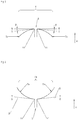
- FIG. 1 is a part of a developed flow channel 1 shown.
- the inner cover strips 2c visible.
- At these two inner shrouds 2c each have an airfoil 2a and 2b are formed, which extend substantially radially.
- These blades 2a and 2b are used in the FIG. 1 From left to right flowing fluid 1 to redirect accordingly.
- the flow channel 1 is divided into smaller passage areas at this axial point in the circumferential direction by the blades 2a and 2b.
- the flow channel 1 is bounded by two opposite side walls.
- the side walls can, as here in the FIG. 1 , of at least two radially inner Cover bands 2c and / or be formed by at least two radially outer shrouds of the blades, which limit a gap extending between them 3 in the circumferential direction u.
- the shrouds 2c here have contouring in the form of an elevation 4 extending over the gap 3, a one-sided elevation 5 adjoining the gap 3 and a one-sided depression 6 adjoining the gap 3.
- the survey 5 and the recess 6 are relative to the gap 3 directly opposite.
- “Survey” means a radial local extent of the shroud 2c with respect to a non-contoured surface portion of the shroud 2c, wherein the survey projects into the annulus.
- Depression means a local extension of the shroud 2c with respect to a non-contoured surface portion of the shroud 2c, the recess pointing radially away from the annulus.
- Fig. 2 shows a sectional view of the survey 4 along the line AA in Fig. 1
- the elevation 4 extends over the gap 3 and for this purpose has two contouring sections 7a, 7b which adjoin the gap 3.
- the contouring sections 7a, 7b are identical here and indicate the elevation 4 extending over the gap 3.
- the straight line S and the tangent T lie in the image plane and thus run along the section line AA in FIG Fig. 1
- the tangent T of the contouring section 7a has a positive slope.
- the tangent T of the contouring section 7b has a negative slope.
- the contouring section 7a merges into an angle ⁇ of 0 ° to + 20 ° in the gap edge 11.
- the contouring section 7b merges into an angle ⁇ of 0 ° to -20 ° into the gap edge 11.
- the angle ⁇ is respectively formed between a tangent T of the contouring section 7a or 7b at the gap edge 11 and a straight line S extending through the gap edge 11 and perpendicular to the gap 3.
- Fig. 3 shows a over a shroud gap 3 extending recess 4a.
- the position and orientation of the recess 4a corresponds to the position and orientation of the survey 4 in FIG. 1
- the depression 4a has a contouring section 7a adjoining the gap 3 and an adjoining section 7b adjoining the gap 3.
- the contouring sections 7a, 7b are here formed the same and suggest the over the gap 3 extending recess 4a.
- the straight line S and the tangent T lie in the image plane.
- the tangent T of the contouring section 7a has a negative slope.
- the tangent T of the contouring section 7b has a positive slope.
- the contouring section 7a merges into an angle ⁇ from 0 ° to -20 ° into a gap edge 11.
- the contouring section 7b merges into an angle ⁇ of 0 ° to + 20 ° into a gap edge 11.
- the angle ⁇ is in each case removed between a tangent T of the contouring section 7a or 7b at the gap edge 11 and a straight line S running through the gap edge 11 and perpendicular to the gap 3.
- Fig. 4 shows a schematic contouring along the line BB in Fig. 1 , Adjacent to the gap 3 is a contouring section 8a and a contouring section 8b.
- the contouring section 8a indicates the recess 6 adjoining the gap edge 11.
- the contouring section 8b indicates the elevation 5 adjoining the gap edge 11.
- the straight line S and the tangent T lie in the image plane and thus run along the section line BB in FIG Fig. 1 ,
- the contouring sections 8a, 8b pass into an angle ⁇ of 0 ° to + 20 ° into the gap edge 11.
- the angle ⁇ is in each case removed between a tangent T of the contouring section 7a or 7b at the gap edge 11 and a straight line S running through the gap edge 11 and perpendicular to the gap 3.
- Fig. 5 shows a contouring.
- the position and orientation of the recess 12 corresponds to the position and orientation of the recess 6 in FIG. 1
- the contouring section 8a is a non-contoured or uncontoured shroud section 10 to the gap 3 at.
- the straight line S and the tangent T lie in the picture plane.
- the contouring section 8a merges into an angle ⁇ of 0 ° to + 20 ° into the gap edge 11.
- the uncontoured shroud section 10 merges into an angle ⁇ of 0 ° in the gap edge 11.
- the angle ⁇ is removed between a tangent T of the contouring section 8a at the gap edge 11 and a straight line S passing through the gap edge 11 and perpendicular to the gap 3.
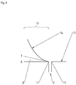
- Fig. 6 shows another alternative contouring. Adjacent to a shroud gap 3 is a contouring section 7a, which indicates an elevation 13. The position and orientation of the elevation 13 corresponds to the position and orientation of the recess 6 in FIG. 1 , Opposite the contouring section 7a, an uncontoured shroud section 10 adjoins the gap 3.
- the straight line S and the tangent T lie in the picture plane.
- the contouring section 7a merges into an angle ⁇ of 0 ° to -20 ° into the gap edge 11.
- the uncontoured shroud section 10 merges into an angle ⁇ of 0 ° in the gap edge 11.
- the angle ⁇ is removed between a tangent T of the contouring section 7a at the gap edge 11 and a straight line S passing through the gap edge 11 and perpendicular to the gap 3.
- the invention relates to a flow channel for a turbomachine, which is bounded in the radial direction of the turbomachine by two opposing and spaced side walls, wherein at least one of the side walls is divided by a circumferential gap into two sections or sidewall sections, wherein at least one side wall portion a Contouring, wherein at least one Kontm istsabterrorism passes at an angle of -20 ° to + 20 ° in a gap edge, which is between a tangent of the contouring section is removed at the gap edge and a straight line passing through the gap edge and perpendicular to the gap.
- Exemplary flow channels are formed by intermediate housings, scoop channels, so-called inner air seals or outer air seals, and the like.
Landscapes
- Engineering & Computer Science (AREA)
- Physics & Mathematics (AREA)
- Fluid Mechanics (AREA)
- Mechanical Engineering (AREA)
- General Engineering & Computer Science (AREA)
- Structures Of Non-Positive Displacement Pumps (AREA)
Priority Applications (1)
| Application Number | Priority Date | Filing Date | Title |
|---|---|---|---|
| EP16160847.6A EP3219914A1 (fr) | 2016-03-17 | 2016-03-17 | Canal d'écoulement, grille d'aubes et turbomachine associées |
Applications Claiming Priority (1)
| Application Number | Priority Date | Filing Date | Title |
|---|---|---|---|
| EP16160847.6A EP3219914A1 (fr) | 2016-03-17 | 2016-03-17 | Canal d'écoulement, grille d'aubes et turbomachine associées |
Publications (1)
| Publication Number | Publication Date |
|---|---|
| EP3219914A1 true EP3219914A1 (fr) | 2017-09-20 |
Family
ID=55542568
Family Applications (1)
| Application Number | Title | Priority Date | Filing Date |
|---|---|---|---|
| EP16160847.6A Withdrawn EP3219914A1 (fr) | 2016-03-17 | 2016-03-17 | Canal d'écoulement, grille d'aubes et turbomachine associées |
Country Status (1)
| Country | Link |
|---|---|
| EP (1) | EP3219914A1 (fr) |
Cited By (2)
| Publication number | Priority date | Publication date | Assignee | Title |
|---|---|---|---|---|
| US20200318483A1 (en) * | 2019-04-08 | 2020-10-08 | United Technologies Corporation | Non-axisymmetric endwall contouring with aft mid-passage peak |
| US20200318484A1 (en) * | 2019-04-08 | 2020-10-08 | United Technologies Corporation | Non-axisymmetric endwall contouring with forward mid-passage peak |
Citations (12)
| Publication number | Priority date | Publication date | Assignee | Title |
|---|---|---|---|---|
| EP1762700A2 (fr) * | 2005-09-13 | 2007-03-14 | Rolls-Royce plc | Aubage de compresseur axial |
| US20100166558A1 (en) * | 2008-12-31 | 2010-07-01 | Siden Gunnar L | Methods and apparatus relating to improved turbine blade platform contours |
| EP2248996A1 (fr) * | 2009-05-04 | 2010-11-10 | Alstom Technology Ltd | Turbine à gaz |
| US20110044818A1 (en) * | 2009-08-20 | 2011-02-24 | Craig Miller Kuhne | Biformal platform turbine blade |
| EP2423437A2 (fr) * | 2010-08-31 | 2012-02-29 | General Electric Company | Ensemble turbine à aubes à parois d'extrémité profilées et synchronisation préférentielle |
| EP2423438A2 (fr) * | 2010-08-31 | 2012-02-29 | General Electric Company | Aube de turbine carénée avec plateforme profilée et segment axial en queue d'aronde |
| US20130004315A1 (en) * | 2011-06-29 | 2013-01-03 | Beeck Alexander R | Mateface gap configuration for gas turbine engine |
| EP2487329B1 (fr) | 2011-02-08 | 2013-11-27 | MTU Aero Engines GmbH | Canal d'aube doté d'une définition de contour de la paroi latérale et turbomachine associé |
| EP2787172A2 (fr) | 2012-08-02 | 2014-10-08 | MTU Aero Engines GmbH | Grille d'aubes avec définition de contour de la paroi latérale et turbomachine |
| US20150147179A1 (en) * | 2008-02-28 | 2015-05-28 | Snecma | Blade with 3d platform comprising an inter-blade bulb |
| EP2696029B1 (fr) | 2012-08-09 | 2015-10-07 | MTU Aero Engines AG | Grille d'aube avec définition de contour de la paroi latérale et turbomachine |
| EP2998509A1 (fr) * | 2014-09-12 | 2016-03-23 | United Technologies Corporation | Paroi d'extrémité profilée pour grilles d'aubes avec géométries différentes |
-
2016
- 2016-03-17 EP EP16160847.6A patent/EP3219914A1/fr not_active Withdrawn
Patent Citations (12)
| Publication number | Priority date | Publication date | Assignee | Title |
|---|---|---|---|---|
| EP1762700A2 (fr) * | 2005-09-13 | 2007-03-14 | Rolls-Royce plc | Aubage de compresseur axial |
| US20150147179A1 (en) * | 2008-02-28 | 2015-05-28 | Snecma | Blade with 3d platform comprising an inter-blade bulb |
| US20100166558A1 (en) * | 2008-12-31 | 2010-07-01 | Siden Gunnar L | Methods and apparatus relating to improved turbine blade platform contours |
| EP2248996A1 (fr) * | 2009-05-04 | 2010-11-10 | Alstom Technology Ltd | Turbine à gaz |
| US20110044818A1 (en) * | 2009-08-20 | 2011-02-24 | Craig Miller Kuhne | Biformal platform turbine blade |
| EP2423437A2 (fr) * | 2010-08-31 | 2012-02-29 | General Electric Company | Ensemble turbine à aubes à parois d'extrémité profilées et synchronisation préférentielle |
| EP2423438A2 (fr) * | 2010-08-31 | 2012-02-29 | General Electric Company | Aube de turbine carénée avec plateforme profilée et segment axial en queue d'aronde |
| EP2487329B1 (fr) | 2011-02-08 | 2013-11-27 | MTU Aero Engines GmbH | Canal d'aube doté d'une définition de contour de la paroi latérale et turbomachine associé |
| US20130004315A1 (en) * | 2011-06-29 | 2013-01-03 | Beeck Alexander R | Mateface gap configuration for gas turbine engine |
| EP2787172A2 (fr) | 2012-08-02 | 2014-10-08 | MTU Aero Engines GmbH | Grille d'aubes avec définition de contour de la paroi latérale et turbomachine |
| EP2696029B1 (fr) | 2012-08-09 | 2015-10-07 | MTU Aero Engines AG | Grille d'aube avec définition de contour de la paroi latérale et turbomachine |
| EP2998509A1 (fr) * | 2014-09-12 | 2016-03-23 | United Technologies Corporation | Paroi d'extrémité profilée pour grilles d'aubes avec géométries différentes |
Cited By (4)
| Publication number | Priority date | Publication date | Assignee | Title |
|---|---|---|---|---|
| US20200318483A1 (en) * | 2019-04-08 | 2020-10-08 | United Technologies Corporation | Non-axisymmetric endwall contouring with aft mid-passage peak |
| US20200318484A1 (en) * | 2019-04-08 | 2020-10-08 | United Technologies Corporation | Non-axisymmetric endwall contouring with forward mid-passage peak |
| US10876411B2 (en) * | 2019-04-08 | 2020-12-29 | United Technologies Corporation | Non-axisymmetric end wall contouring with forward mid-passage peak |
| US10968748B2 (en) * | 2019-04-08 | 2021-04-06 | United Technologies Corporation | Non-axisymmetric end wall contouring with aft mid-passage peak |
Similar Documents
| Publication | Publication Date | Title |
|---|---|---|
| EP1515000B1 (fr) | Aubage d'une turbomachine avec un carenage contouré | |
| DE60211061T2 (de) | Axialturbine mit einer Stufe in einem Abströmkanal | |
| DE102008044471A1 (de) | Kompressionslabyrinthdichtung und Turbine mit dieser | |
| DE102015111750A1 (de) | Gekühltes Turbinenlaufrad für ein Flugtriebwerk | |
| EP3121371B1 (fr) | Turbine comprenant des aubes directrices refroidies | |
| CH707543A2 (de) | Turbomaschine mit wirbelhemmender Dichtung. | |
| DE102012013160A1 (de) | Labyrinthdichtungen | |
| DE102007046252A1 (de) | Feststehende-Rotierende Anordnungen mit Oberflächenmerkmalen zum verbesserten Einschluss von Fluidströmung, und verwandte Prozesse | |
| EP2294286B1 (fr) | Rotor avex aubes mobiles carenées d'une turbomachine | |
| EP2647795A1 (fr) | Système d'étanchéité pour turbomachine | |
| EP2787171A2 (fr) | Grille d'aubes avec définition de contour de la paroi latérale et turbomachine | |
| EP3404210A1 (fr) | Segment de grille d'aubes d'une turbomachine avec paroi de plateforme non-axisymétrique , grille d'aubes, canal d'aube, plateforme, turbomachine associés | |
| DE102012100771A1 (de) | Verfahren und Vorrichtung für einen Labyrinthdichtungspackungsring | |
| DE102015122928A1 (de) | Gasturbinendichtung | |
| EP2179143A2 (fr) | Installation de turbine à gaz | |
| DE102015203871A1 (de) | Rotor einer Turbine einer Gasturbine mit verbesserter Kühlluftführung | |
| DE102014114555A1 (de) | Verriegelnde Abstandshalteranordnung | |
| EP3388626B1 (fr) | Contournage d'une plate-forme de grille d'aube | |
| EP2913481B1 (fr) | Aubes en tandem d'une turbomachine | |
| EP2584148A1 (fr) | Aube de turbine refroidie par film pour une turbomachine | |
| EP2990605A1 (fr) | Aube de turbine | |
| DE102010037692A1 (de) | Geformte Wabendichtung für eine Turbomaschine | |
| EP2787178B1 (fr) | Ensemble d'aube directrice | |
| EP3219914A1 (fr) | Canal d'écoulement, grille d'aubes et turbomachine associées | |
| EP1706595B1 (fr) | Turbomachine comprenant un canal en spirale dans la partie mediane du carter |
Legal Events
| Date | Code | Title | Description |
|---|---|---|---|
| PUAI | Public reference made under article 153(3) epc to a published international application that has entered the european phase |
Free format text: ORIGINAL CODE: 0009012 |
|
| AK | Designated contracting states |
Kind code of ref document: A1 Designated state(s): AL AT BE BG CH CY CZ DE DK EE ES FI FR GB GR HR HU IE IS IT LI LT LU LV MC MK MT NL NO PL PT RO RS SE SI SK SM TR |
|
| AX | Request for extension of the european patent |
Extension state: BA ME |
|
| STAA | Information on the status of an ep patent application or granted ep patent |
Free format text: STATUS: THE APPLICATION IS DEEMED TO BE WITHDRAWN |
|
| 18D | Application deemed to be withdrawn |
Effective date: 20180321 |