EP3219664A1 - Liquid supply apparatus - Google Patents
Liquid supply apparatus Download PDFInfo
- Publication number
- EP3219664A1 EP3219664A1 EP15859124.8A EP15859124A EP3219664A1 EP 3219664 A1 EP3219664 A1 EP 3219664A1 EP 15859124 A EP15859124 A EP 15859124A EP 3219664 A1 EP3219664 A1 EP 3219664A1
- Authority
- EP
- European Patent Office
- Prior art keywords
- balloon
- supply apparatus
- support member
- liquid supply
- casing
- Prior art date
- Legal status (The legal status is an assumption and is not a legal conclusion. Google has not performed a legal analysis and makes no representation as to the accuracy of the status listed.)
- Withdrawn
Links
- 239000007788 liquid Substances 0.000 title claims abstract description 115
- 230000000384 rearing effect Effects 0.000 claims description 7
- 238000004891 communication Methods 0.000 claims description 6
- 239000012530 fluid Substances 0.000 claims description 6
- 229920002379 silicone rubber Polymers 0.000 claims description 3
- 239000004945 silicone rubber Substances 0.000 claims description 3
- XLYOFNOQVPJJNP-UHFFFAOYSA-N water Substances O XLYOFNOQVPJJNP-UHFFFAOYSA-N 0.000 description 48
- 241000699670 Mus sp. Species 0.000 description 14
- 230000005484 gravity Effects 0.000 description 8
- 239000008400 supply water Substances 0.000 description 8
- 230000008602 contraction Effects 0.000 description 4
- 239000003814 drug Substances 0.000 description 4
- 229940079593 drug Drugs 0.000 description 4
- 230000000694 effects Effects 0.000 description 3
- 230000005486 microgravity Effects 0.000 description 3
- IJGRMHOSHXDMSA-UHFFFAOYSA-N Atomic nitrogen Chemical compound N#N IJGRMHOSHXDMSA-UHFFFAOYSA-N 0.000 description 2
- 241001465754 Metazoa Species 0.000 description 2
- 235000020888 liquid diet Nutrition 0.000 description 2
- 239000000463 material Substances 0.000 description 2
- 238000011084 recovery Methods 0.000 description 2
- 238000007920 subcutaneous administration Methods 0.000 description 2
- 239000007789 gas Substances 0.000 description 1
- 238000012423 maintenance Methods 0.000 description 1
- 238000012986 modification Methods 0.000 description 1
- 230000004048 modification Effects 0.000 description 1
- 229910052757 nitrogen Inorganic materials 0.000 description 1
Images


Classifications
-
- A—HUMAN NECESSITIES
- A01—AGRICULTURE; FORESTRY; ANIMAL HUSBANDRY; HUNTING; TRAPPING; FISHING
- A01K—ANIMAL HUSBANDRY; CARE OF BIRDS, FISHES, INSECTS; FISHING; REARING OR BREEDING ANIMALS, NOT OTHERWISE PROVIDED FOR; NEW BREEDS OF ANIMALS
- A01K7/00—Watering equipment for stock or game
- A01K7/02—Automatic devices ; Medication dispensers
-
- B—PERFORMING OPERATIONS; TRANSPORTING
- B67—OPENING, CLOSING OR CLEANING BOTTLES, JARS OR SIMILAR CONTAINERS; LIQUID HANDLING
- B67D—DISPENSING, DELIVERING OR TRANSFERRING LIQUIDS, NOT OTHERWISE PROVIDED FOR
- B67D1/00—Apparatus or devices for dispensing beverages on draught
- B67D1/08—Details
- B67D1/0889—Supports
- B67D1/0894—Supports for the vessel to be filled
-
- A—HUMAN NECESSITIES
- A01—AGRICULTURE; FORESTRY; ANIMAL HUSBANDRY; HUNTING; TRAPPING; FISHING
- A01K—ANIMAL HUSBANDRY; CARE OF BIRDS, FISHES, INSECTS; FISHING; REARING OR BREEDING ANIMALS, NOT OTHERWISE PROVIDED FOR; NEW BREEDS OF ANIMALS
- A01K7/00—Watering equipment for stock or game
- A01K7/02—Automatic devices ; Medication dispensers
- A01K7/022—Pumps actuated by the drinking animal
-
- A—HUMAN NECESSITIES
- A61—MEDICAL OR VETERINARY SCIENCE; HYGIENE
- A61M—DEVICES FOR INTRODUCING MEDIA INTO, OR ONTO, THE BODY; DEVICES FOR TRANSDUCING BODY MEDIA OR FOR TAKING MEDIA FROM THE BODY; DEVICES FOR PRODUCING OR ENDING SLEEP OR STUPOR
- A61M5/00—Devices for bringing media into the body in a subcutaneous, intra-vascular or intramuscular way; Accessories therefor, e.g. filling or cleaning devices, arm-rests
- A61M5/178—Syringes
-
- B—PERFORMING OPERATIONS; TRANSPORTING
- B67—OPENING, CLOSING OR CLEANING BOTTLES, JARS OR SIMILAR CONTAINERS; LIQUID HANDLING
- B67D—DISPENSING, DELIVERING OR TRANSFERRING LIQUIDS, NOT OTHERWISE PROVIDED FOR
- B67D3/00—Apparatus or devices for controlling flow of liquids under gravity from storage containers for dispensing purposes
- B67D3/04—Liquid-dispensing taps or cocks adapted to seal and open tapping holes of casks, e.g. for beer
- B67D3/042—Liquid-dispensing taps or cocks adapted to seal and open tapping holes of casks, e.g. for beer operated by deforming a membrane-like closing element
-
- A—HUMAN NECESSITIES
- A61—MEDICAL OR VETERINARY SCIENCE; HYGIENE
- A61M—DEVICES FOR INTRODUCING MEDIA INTO, OR ONTO, THE BODY; DEVICES FOR TRANSDUCING BODY MEDIA OR FOR TAKING MEDIA FROM THE BODY; DEVICES FOR PRODUCING OR ENDING SLEEP OR STUPOR
- A61M5/00—Devices for bringing media into the body in a subcutaneous, intra-vascular or intramuscular way; Accessories therefor, e.g. filling or cleaning devices, arm-rests
- A61M5/14—Infusion devices, e.g. infusing by gravity; Blood infusion; Accessories therefor
- A61M5/142—Pressure infusion, e.g. using pumps
- A61M5/145—Pressure infusion, e.g. using pumps using pressurised reservoirs, e.g. pressurised by means of pistons
- A61M5/148—Pressure infusion, e.g. using pumps using pressurised reservoirs, e.g. pressurised by means of pistons flexible, e.g. independent bags
- A61M5/152—Pressure infusion, e.g. using pumps using pressurised reservoirs, e.g. pressurised by means of pistons flexible, e.g. independent bags pressurised by contraction of elastic reservoirs
-
- B—PERFORMING OPERATIONS; TRANSPORTING
- B65—CONVEYING; PACKING; STORING; HANDLING THIN OR FILAMENTARY MATERIAL
- B65D—CONTAINERS FOR STORAGE OR TRANSPORT OF ARTICLES OR MATERIALS, e.g. BAGS, BARRELS, BOTTLES, BOXES, CANS, CARTONS, CRATES, DRUMS, JARS, TANKS, HOPPERS, FORWARDING CONTAINERS; ACCESSORIES, CLOSURES, OR FITTINGS THEREFOR; PACKAGING ELEMENTS; PACKAGES
- B65D83/00—Containers or packages with special means for dispensing contents
- B65D83/0055—Containers or packages provided with a flexible bag or a deformable membrane or diaphragm for expelling the contents
- B65D83/0061—Containers or packages provided with a flexible bag or a deformable membrane or diaphragm for expelling the contents the contents of a flexible bag being expelled by the contracting forces inherent in the bag or a sleeve fitting snugly around the bag
Definitions
- the present invention relates to a liquid supply apparatus and more particularly to a liquid supply apparatus for supplying a liquid for rearing organisms such as mice.
- examples of facilities for supplying water or the like to mice or the like in outer space may be considered to include a device for automatically supplying water or the like using a motor-driven syringe pump or the like.
- a motor-driven device needs a power supply and has a relatively heavy weight and large footprint. Therefore, it is not preferable to install such a motor-driven device in a spacecraft with limited loading weight and loading space.
- motor-driven devices may fail. A failure of the motor-driven device requires a repair by an astronaut and involves a time-consuming maintenance and management effort.
- Patent Literature 1 Japanese Patent Laid-Open No. 2002-017191
- an object of the present invention is to provide a liquid supply apparatus eliminating the need for a power supply, having relatively light weight and small footprint, and ensuring a stable liquid supply.
- a liquid supply apparatus includes a first support member; a second support member; a balloon having one end supported by the first support member and another end supported by the second support member; and a casing having a constant longitudinal length.
- the balloon is disposed in the casing and is configured so as to be able to hold therein a liquid to be supplied and discharge the held liquid. When the balloon holds the liquid, the one end and the other end of the balloon are positioned in the case.
- the first support member is fixed to one end of the casing
- the second support member is fixed to another end of the casing
- the balloon is supported by the first support member and the second support member in a state where a tensile stress is applied.
- the balloon is supported by the first support member and the second support member in a state where a tensile stress is applied so as to have a length of 1.5 times or more in an axial direction of the first support member than that in a state where no tensile stress is applied.
- the first support member is fixed to one end of the casing, and when the balloon holds the liquid, an axial expansion coefficient of the first support member of the balloon is greater than a radial expansion coefficient of the first support member of the balloon.
- the first support member includes an outlet port for letting out the liquid held in the balloon;
- the second support member includes a filling port for filling the liquid into the balloon;
- the balloon includes an outlet hole in fluid communication with the outlet port of the first support member and a filling hole in fluid communication with the filling port of the second support member.
- the balloon is made of silicone rubber.
- the liquid is a liquid for rearing organisms.
- the liquid supply apparatus is used in outer space.
- the present invention can provide a liquid supply apparatus eliminating the need for a power supply, having relatively light weight and small footprint, and ensuring a stable liquid supply.
- Figures 1A to 1C each are a schematic side view of a liquid supply apparatus according to a first embodiment of the present invention.
- Figure 1A illustrates the liquid supply apparatus excluding a casing.
- Figure 1B illustrates the liquid supply apparatus including a casing.
- Figure 1C illustrates the liquid supply apparatus including the casing in which a liquid is filled.
- the liquid supply apparatus according to the first embodiment can be used, for example, in outer space to supply water or liquid diet (organism rearing liquid, hereinafter referred to as water or the like) to organisms such as mice to be reared in outer space.
- the liquid supply apparatus according to the first embodiment can be mounted on a spacecraft for launch and/or recovery.
- the liquid supply apparatus includes a first shaft 10 (first support member); a second shaft 11 (second support member) disposed in series (coaxially) with the first shaft 10; a balloon 12 having one end supported by the first shaft 10 and the other end supported by the second shaft 11; and a substantially cylindrical fixed plate 13 fixed to the first shaft 10.
- the balloon 12 is configured so as to be able to hold therein water or the like to be supplied to organisms such as mice and discharge the water or the like therefrom.
- the first shaft 10 is a substantially cylindrical member.
- the first shaft 10 includes therein an outlet port 10a for letting out the water or the like held in the balloon 12.
- the outlet port 10a extends from one end of the first shaft 10 to the other end thereof.
- the second shaft 11 is a substantially cylindrical member.
- the second shaft 11 includes therein a filling port 11a for filling water or the like into the balloon 12.
- the filling port 11a extends from one end of the second shaft 11 to the other end thereof.
- the filling port 11a is configured to be opened and closed by an unillustrated lid.
- the outlet port 10a connects to an unillustrated pipe or the like.
- the balloon 12 is a substantially cylindrical elastic member.
- the material of the balloon 12 is not particularly limited, but from the viewpoint of biocompatibility, for example, silicone rubber or the like is preferable.
- the balloon 12 is configured to be able to hold, for example, approximately 250 mL of water or the like.
- the balloon 12 includes an outlet hole 12a provided on one end thereof.
- the balloon 12 is in close contact with the outer periphery of the first shaft 10 via the outlet hole 12a.
- the outlet port 10a of the first shaft 10 is in fluid communication with the outlet hole 12a of the balloon 12, and the inner space of the balloon 12 communicates with the outer space via the outlet port 10a.
- the balloon 12 includes a filling hole 12b provided on the other end thereof.
- the balloon 12 is in sealingly contact with the outer periphery of the second shaft 11 via the filling hole 12b.
- the filling port 11a of the second shaft 11 is in fluid communication with the filling hole 12b of the balloon 12, and the inner space of the balloon 12 communicates with the outer space via the filling port 11a.
- the liquid supply apparatus further includes a tubular casing 30 having a constant longitudinal length.
- tubular is not limited to a cylindrical shape but includes a rectangular tubular shape having a polygonal cross section.
- the casing 30 includes a substantially circular first opening 30a provided in a first end portion 31; and a substantially circular second opening 30b provided in a second end portion 32 opposite to the first end portion 31.
- the casing 30 includes therein the first shaft 10, the balloon 12, and the second shaft 11.
- the fixed plate 13 is fixed to the first end portion 31 of the casing 30 so as to close the first opening 30a of the casing 30. Therefore, one end portion of the first shaft 10 is positioned outside the casing 30.
- the balloon 12 or the second shaft 11 does not contact the casing 30 and is not fixed thereto.
- the fixed plate 13 When the fixed plate 13 is fixed to the first end portion 31, first, the first shaft 10 including the fixed plate 13, the balloon 12, and the second shaft 11 are inserted into the casing 30 through the first opening 30a. Then, the fixed plate 13 is fixed to the first end portion 31 of the casing 30 from outside the casing 30 so that the fixed plate 13 closes the first opening 30a.
- an unillustrated liquid source is connected to the filling port 11a of the second shaft 11 to supply water or the like into the balloon 12.
- an unillustrated pipe or the like connected to the outlet port 10a of the first shaft 10 is closed by a valve or the like to prevent water or the like supplied into the balloon 12 from continuing to flow out of the outlet port 10a.
- the balloon 12 inflates in the axial direction of the first shaft 10 and in the radial direction of the first shaft 10 as illustrated in FIG. 1C .
- the balloon 12 can be inflated so as to be oriented in a predetermined direction by preliminarily inflating the balloon 12 into a desired shape using a gas such as air and nitrogen. More specifically, the balloon 12 can be more easily inflated in the axial direction of the first shaft 10 than in the radial direction thereof.
- the axial expansion coefficient of the first shaft 10 of the balloon 12 is greater than the radial expansion coefficient of the first shaft 10 of the balloon 12. This configuration can suppress the balloon 12 from contacting the inner surface of the casing 30 before being completely inflated.
- the second shaft 11 moves in an (axial) direction away from the first shaft 10.
- the balloon 12 is completely inflated by holding water or the like, one end supported by the first shaft 10 of the balloon 12 and the other end supported by the second shaft 11 are positioned so as to be contained within the casing 30.
- the balloon 12 is inflated so as not to protrude from the casing 30. This configuration ensures that the balloon 12 is always located within the casing 30, can prevent the balloon 12 from contacting external objects, and can prevent the balloon 12 from being damaged.
- a valve of an unillustrated pipe or the like connected to the first shaft 10 is opened. Then, the contraction force of the balloon 12 causes the water or the like inside the balloon 12 to be pushed out from the outlet port 10a into the pipe, whereby the water or the like can be automatically supplied to organisms such as mice.
- the liquid supply apparatus according to the first embodiment can stably supply water or the like by the contraction force of the balloon 12, and thus can eliminate the need for a power supply for supplying water or the like.
- the liquid supply apparatus according to the first embodiment eliminates the need for a power supply and thus can relatively reduce weight and foot print more than the conventional liquid supply apparatus needing an electric power supply or the like.
- the liquid supply apparatus includes a casing 30 having a constant longitudinal length, and the balloon 12 is disposed in the casing 30.
- the balloon 12 holds liquid, one end and the other end of the balloon are positioned in the casing 30. This configuration ensures that the balloon 12 is always located within the casing 30, can prevent the balloon 12 from contacting external objects, and can prevent the balloon 12 from being damaged.
- the first shaft 10 is fixed to one end of the casing 30.
- the axial expansion coefficient of the first shaft 10 of the balloon 12 is greater than the radial expansion coefficient of the first shaft 10 of the balloon 12. This configuration can suppress the balloon 12 from contacting the inner surface of the casing 30 before being completely inflated.
- the first shaft 10 includes the outlet port 10a and the second shaft 11 includes the filling port 11a.
- the filling port 11a for filling water or the like is provided separately from the outlet port 10a for letting out water or the like, but another embodiment may be configured so as to fill water or the like through the outlet port 10a. In this case, in a state where the filling port 11a is closed, a liquid source is connected to the outlet port 10a to fill water or the like thereinto, and then a pipe or the like may be connected to the outlet port 10a.
- the liquid supply apparatus according to the first embodiment can be used not only in outer space (zero gravity environment, microgravity environment) but also on the ground. In the case of an automatic liquid supply apparatus using gravity, a tank must be positioned higher than a supply port (outlet port) for water or the like. In contrast to this, the liquid supply apparatus according to the first embodiment is advantageous in that the positional relationship between the outlet port 10a and the balloon 12 is not limited to this position. In addition, the liquid supply apparatus according to the first embodiment can reduce the capacity of the balloon 12 (approximately 5 to 20 mL) to be used in conjunction with an orifice, thereby allowing continuous subcutaneous administration of drugs to a small animal. The liquid supply apparatus according to the first embodiment allows continuous administration of drugs, for example, at a flow rate of at least 0.5 mL/hr.
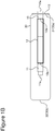
- Figures 2A to 2C each are a schematic side view of a liquid supply apparatus according to a second embodiment of the present invention.
- Figure 2A illustrates the liquid supply apparatus excluding a casing.
- Figure 2B illustrates the liquid supply apparatus including a casing.
- Figure 2C illustrates the liquid supply apparatus including the casing in which a liquid is filled.
- the liquid supply apparatus according to the second embodiment can be used, for example, in outer space to supply water or the like for rearing organisms such as mice to be reared in outer space, in the same manner as the liquid supply apparatus according to the first embodiment.
- the liquid supply apparatus according to the second embodiment can be mounted on a spacecraft on orbit.
- the liquid supply apparatus according to the second embodiment differs from the liquid supply apparatus according to the first embodiment mainly in that the second shaft 11 is fixed to the casing 30.
- the same reference numerals or characters are assigned to the components same as or similar to those of the liquid supply apparatus according to the first embodiment, and the duplicate description is omitted.
- the liquid supply apparatus excluding the casing 30 according to the second embodiment has the same configuration as the liquid supply apparatus excluding the casing 30 according to the first embodiment illustrated in Figure 1A .
- the second shaft 11 includes a substantially cylindrical fixed plate 15.
- the casing 30 includes therein the first shaft 10, the balloon 12, and the second shaft 11.
- the balloon 12 of the liquid supply apparatus according to the second embodiment is configured so as to be able to hold, for example, approximately 70 mL of water or the like.
- the fixed plate 13 is fixed to the first end portion 31 of the casing 30 so as to close the first opening 30a of the casing 30. Therefore, one end portion of the first shaft 10 is positioned outside the casing 30.
- the fixed plate 15 is fixed to the second end portion 32 of the casing 30 so as to close the second opening 30b of the casing 30.
- one end portion of the second shaft 11 is positioned outside the casing 30.
- the fixed plate 13 and the fixed plate 15 are fixed to the first end portion 31 and the second end portion 32 respectively, first, the first shaft 10 including the fixed plate 13, the balloon 12, and the second shaft 11 are inserted into the casing 30 through the first opening 30a. Then, the fixed plate 13 is fixed to the first end portion 31 from outside the casing 30.
- the fixed plate 13 In a state in which the fixed plate 13 is fixed to the first end portion 31, the second shaft 11 is pulled toward the second end portion 32 (a tensile stress is applied) to stretch the balloon 12.
- the fixed plate 15 In a state in which the balloon 12 is stretched to a position (position illustrated in Figure 2C ) where one end portion of the second shaft 11 protrudes from the casing 30, the fixed plate 15 is attached to the second shaft 11.
- the balloon 12 is preferably stretched to have a length of approximately 1.5 times or more in the axial direction of the first shaft 10 than that in a state (state illustrated in Figure 2A ) where no tensile stress is applied.
- the fixed plate 15 is fixed to the second end portion 32 from outside the casing 30.
- the balloon 12 is fixed to the first shaft 10 and the second shaft 11 in a state where a tensile stress is applied.
- an unillustrated liquid source is connected to the filling port 11a of the second shaft 11 to supply water or the like into the balloon 12.
- an unillustrated pipe or the like connected to the outlet port 10a of the first shaft 10 is closed by a valve or the like to prevent water or the like supplied into the balloon 12 from continuing to flow out of the outlet port 10a.
- the first shaft 10 and the second shaft 11 are fixed to the first end portion 31 and the second end portion 32 of the casing 30 by the fixed plate 13 and the fixed plate 15 respectively in a state where a tensile stress is applied to the balloon 12.
- the balloon 12 When the thus configured balloon 12 is filled with water or the like, the balloon 12 can be suppressed from stretching in the axial direction of the first shaft 10 and the balloon 12 can be inflated in the radial direction of the first shaft 10.
- This configuration can suppress the balloon 12 from contacting the inner surface of the casing 30 before being completely inflated and can prevent inflation failure due to contacting of the balloon 12 with the inner surface of the casing 30.
- a valve of an unillustrated pipe or the like connected to the first shaft 10 is opened. Then, the contraction force of the balloon 12 causes the water or the like inside the balloon 12 to be pushed out from the outlet port 10a into the pipe, whereby the water or the like can be automatically supplied to organisms such as mice.
- the liquid supply apparatus according to the second embodiment can stably supply water or the like by the contraction force of the balloon 12, and thus can eliminate the need for a power supply for supplying water or the like.
- the liquid supply apparatus according to the second embodiment eliminates the need for a power supply and thus can relatively reduce weight and foot print more than the conventional liquid supply apparatus needing an electric power supply or the like.
- the liquid supply apparatus includes a casing 30 having a constant longitudinal length, and the balloon 12 is disposed in the casing 30.
- the balloon 12 holds liquid, one end and the other end of the balloon are positioned in the casing 30. This configuration ensures that the balloon 12 is always located within the casing 30, can prevent the balloon 12 from contacting external objects, and can prevent the balloon 12 from being damaged.
- the first shaft 10 is fixed to the first end portion 31 of the casing 30 and the second shaft 11 is fixed to the second end portion 32.
- the balloon 12 is supported by the first shaft 10 and the second shaft 11 in a state where a tensile stress is applied.
- the balloon 12 has a constant axial width along the first shaft 10.
- the balloon 12 can be suppressed from inflating in the axial direction of the first shaft 10 and the balloon 12 inflates in the radial direction of the first shaft 10, and thus the inflation shape of the balloon 12 can be controlled. Therefore, the balloon 12 can be inflated into a desired shape inside the casing 30, and the balloon 12 can hold more water or the like in the limited space inside the casing 30.
- the balloon 12 is supported by the first shaft 10 and the second shaft 11 in a state where a tensile stress is applied to have a length of 1.5 times or more in the axial direction of the first shaft 10 than that in a state where no tensile stress is applied.
- This configuration can more reliably suppress the balloon 12 from inflating in the axial direction of the first shaft 10 and can inflate the balloon 12 in the radial direction of the first shaft 10.
- the first shaft 10 includes the outlet port 10a and the second shaft 11 includes the filling port 11a.
- the outlet port 10a connects to an unillustrated pipe or the like, water or the like can be filled into the balloon 12 through the filling port 11a.
- the filling port 11a for filling water or the like is provided separately from the outlet port 10a for letting out water or the like, but another embodiment may be configured so as to fill water or the like through the outlet port 10a.
- a liquid source is connected to the outlet port 10a to fill water or the like thereinto, and then a pipe or the like for letting out water or the like may be connected to the outlet port 10a.
- the liquid supply apparatus according to the second embodiment can be used not only in outer space (zero gravity environment, microgravity environment) but also on the ground. In the case of an automatic liquid supply apparatus using gravity, a tank must be positioned higher than a supply port (outlet port) for water or the like. In contrast to this, the liquid supply apparatus according to the second embodiment is advantageous in that the positional relationship between the outlet port 10a and the balloon 12 is not limited to this position. In addition, the liquid supply apparatus according to the second embodiment can reduce the capacity of the balloon 12 (approximately 5 to 20 mL) to be used in conjunction with an orifice, thereby allowing continuous subcutaneous administration of drugs to a small animal. The liquid supply apparatus according to the second embodiment allows continuous administration of drugs, for example, at a flow rate of at least 0.5 mL/hr.
- liquid supply apparatus can also be mounted on a spacecraft on orbit.
- liquid supply apparatus according to the second embodiment can also be mounted on a spacecraft for launch and/or recovery.
Abstract


Description
- The present invention relates to a liquid supply apparatus and more particularly to a liquid supply apparatus for supplying a liquid for rearing organisms such as mice.
- Recent years have seen experiments conducted for the purpose of studying the effects of a zero gravity environment or a microgravity environment on organisms in outer space so as to rear organisms such as mice flown on a spacecraft such as space shuttle in outer space. The rearing environment for mice or the like in outer space requires facilities for supplying mice or the like with water or liquid diet (hereinafter referred to as water or the like) in the same manner as in the case of rearing mice or the like on the ground. Examples of common facilities for supplying water or the like to mice or the like on the ground include an automatic liquid supply apparatus using gravity. However, such an automatic liquid supply apparatus using gravity cannot be used in a zero gravity environment.
- In light of this, examples of facilities for supplying water or the like to mice or the like in outer space may be considered to include a device for automatically supplying water or the like using a motor-driven syringe pump or the like. However, such a motor-driven device needs a power supply and has a relatively heavy weight and large footprint. Therefore, it is not preferable to install such a motor-driven device in a spacecraft with limited loading weight and loading space. In addition, motor-driven devices may fail. A failure of the motor-driven device requires a repair by an astronaut and involves a time-consuming maintenance and management effort.
- Patent Literature 1: Japanese Patent Laid-Open No.
2002-017191 - In view of the problems of the prior art described above, the present invention has been made, and an object of the present invention is to provide a liquid supply apparatus eliminating the need for a power supply, having relatively light weight and small footprint, and ensuring a stable liquid supply.
- A liquid supply apparatus according to an embodiment of the present invention includes a first support member; a second support member; a balloon having one end supported by the first support member and another end supported by the second support member; and a casing having a constant longitudinal length. The balloon is disposed in the casing and is configured so as to be able to hold therein a liquid to be supplied and discharge the held liquid. When the balloon holds the liquid, the one end and the other end of the balloon are positioned in the case.
- In the liquid supply apparatus according to another embodiment of the present invention, the first support member is fixed to one end of the casing, the second support member is fixed to another end of the casing, and the balloon is supported by the first support member and the second support member in a state where a tensile stress is applied.
- In the liquid supply apparatus according to yet another embodiment of the present invention, the balloon is supported by the first support member and the second support member in a state where a tensile stress is applied so as to have a length of 1.5 times or more in an axial direction of the first support member than that in a state where no tensile stress is applied.
- In the liquid supply apparatus according to yet another embodiment of the present invention, the first support member is fixed to one end of the casing, and when the balloon holds the liquid, an axial expansion coefficient of the first support member of the balloon is greater than a radial expansion coefficient of the first support member of the balloon.
- In the liquid supply apparatus according to yet another embodiment of the present invention, the first support member includes an outlet port for letting out the liquid held in the balloon; the second support member includes a filling port for filling the liquid into the balloon; and the balloon includes an outlet hole in fluid communication with the outlet port of the first support member and a filling hole in fluid communication with the filling port of the second support member.
- In the liquid supply apparatus according to yet another embodiment of the present invention, the balloon is made of silicone rubber.
- In the liquid supply apparatus according to yet another embodiment of the present invention, the liquid is a liquid for rearing organisms.
- In the liquid supply apparatus according to yet another embodiment of the present invention, the liquid supply apparatus is used in outer space.
- The present invention can provide a liquid supply apparatus eliminating the need for a power supply, having relatively light weight and small footprint, and ensuring a stable liquid supply.
-
-
Figure 1A is a schematic side view of a liquid supply apparatus according to a first embodiment of the present invention. -
Figure 1B is a schematic side view of the liquid supply apparatus according to the first embodiment of the present invention. -
Figure 1C is a schematic side view of the liquid supply apparatus according to the first embodiment of the present invention. -
Figure 2A is a schematic side view of a liquid supply apparatus according to a second embodiment of the present invention. -
Figure 2B is a schematic side view of the liquid supply apparatus according to the second embodiment of the present invention. -
Figure 2C is a schematic side view of the liquid supply apparatus according to the second embodiment of the present invention. - Hereinafter, the embodiments of the present invention will be described with reference to the drawings. In the drawings described below, the same reference numerals or characters are assigned to the same or similar components, and the duplicate description is omitted.
-
Figures 1A to 1C each are a schematic side view of a liquid supply apparatus according to a first embodiment of the present invention.Figure 1A illustrates the liquid supply apparatus excluding a casing.Figure 1B illustrates the liquid supply apparatus including a casing.Figure 1C illustrates the liquid supply apparatus including the casing in which a liquid is filled. The liquid supply apparatus according to the first embodiment can be used, for example, in outer space to supply water or liquid diet (organism rearing liquid, hereinafter referred to as water or the like) to organisms such as mice to be reared in outer space. In particular, the liquid supply apparatus according to the first embodiment can be mounted on a spacecraft for launch and/or recovery. - As illustrated in
Figure 1A , the liquid supply apparatus includes a first shaft 10 (first support member); a second shaft 11 (second support member) disposed in series (coaxially) with thefirst shaft 10; aballoon 12 having one end supported by thefirst shaft 10 and the other end supported by thesecond shaft 11; and a substantially cylindricalfixed plate 13 fixed to thefirst shaft 10. - The
balloon 12 is configured so as to be able to hold therein water or the like to be supplied to organisms such as mice and discharge the water or the like therefrom. Thefirst shaft 10 is a substantially cylindrical member. Thefirst shaft 10 includes therein anoutlet port 10a for letting out the water or the like held in theballoon 12. Theoutlet port 10a extends from one end of thefirst shaft 10 to the other end thereof. Thesecond shaft 11 is a substantially cylindrical member. Thesecond shaft 11 includes therein afilling port 11a for filling water or the like into theballoon 12. Thefilling port 11a extends from one end of thesecond shaft 11 to the other end thereof. Thefilling port 11a is configured to be opened and closed by an unillustrated lid. Theoutlet port 10a connects to an unillustrated pipe or the like. - The
balloon 12 is a substantially cylindrical elastic member. The material of theballoon 12 is not particularly limited, but from the viewpoint of biocompatibility, for example, silicone rubber or the like is preferable. Theballoon 12 is configured to be able to hold, for example, approximately 250 mL of water or the like. - The
balloon 12 includes anoutlet hole 12a provided on one end thereof. Theballoon 12 is in close contact with the outer periphery of thefirst shaft 10 via theoutlet hole 12a. Thus, theoutlet port 10a of thefirst shaft 10 is in fluid communication with theoutlet hole 12a of theballoon 12, and the inner space of theballoon 12 communicates with the outer space via theoutlet port 10a. In addition, theballoon 12 includes afilling hole 12b provided on the other end thereof. Theballoon 12 is in sealingly contact with the outer periphery of thesecond shaft 11 via thefilling hole 12b. Thus, thefilling port 11a of thesecond shaft 11 is in fluid communication with thefilling hole 12b of theballoon 12, and the inner space of theballoon 12 communicates with the outer space via thefilling port 11a. - As illustrated in
Figure 1B , the liquid supply apparatus according to the first embodiment further includes atubular casing 30 having a constant longitudinal length. Note that as used herein, the term "tubular" is not limited to a cylindrical shape but includes a rectangular tubular shape having a polygonal cross section. Thecasing 30 includes a substantially circularfirst opening 30a provided in afirst end portion 31; and a substantially circularsecond opening 30b provided in asecond end portion 32 opposite to thefirst end portion 31. Thecasing 30 includes therein thefirst shaft 10, theballoon 12, and thesecond shaft 11. The fixedplate 13 is fixed to thefirst end portion 31 of thecasing 30 so as to close thefirst opening 30a of thecasing 30. Therefore, one end portion of thefirst shaft 10 is positioned outside thecasing 30. Theballoon 12 or thesecond shaft 11 does not contact thecasing 30 and is not fixed thereto. - When the fixed
plate 13 is fixed to thefirst end portion 31, first, thefirst shaft 10 including the fixedplate 13, theballoon 12, and thesecond shaft 11 are inserted into thecasing 30 through thefirst opening 30a. Then, the fixedplate 13 is fixed to thefirst end portion 31 of thecasing 30 from outside thecasing 30 so that the fixedplate 13 closes thefirst opening 30a. - In order to cause the
balloon 12 of the liquid supply apparatus to hold water or the like, an unillustrated liquid source is connected to the fillingport 11a of thesecond shaft 11 to supply water or the like into theballoon 12. Note that an unillustrated pipe or the like connected to theoutlet port 10a of thefirst shaft 10 is closed by a valve or the like to prevent water or the like supplied into theballoon 12 from continuing to flow out of theoutlet port 10a. As water or the like is supplied into theballoon 12, theballoon 12 inflates in the axial direction of thefirst shaft 10 and in the radial direction of thefirst shaft 10 as illustrated inFIG. 1C . Note that if theballoon 12 contacts the inner side surface of thecasing 30 before theballoon 12 is completely inflated by being filled with a predetermined amount of water or the like, the contact may prevent the inflation. In light of this, theballoon 12 can be inflated so as to be oriented in a predetermined direction by preliminarily inflating theballoon 12 into a desired shape using a gas such as air and nitrogen. More specifically, theballoon 12 can be more easily inflated in the axial direction of thefirst shaft 10 than in the radial direction thereof. Thus, when theballoon 12 is completely inflated by holding water or the like, the axial expansion coefficient of thefirst shaft 10 of theballoon 12 is greater than the radial expansion coefficient of thefirst shaft 10 of theballoon 12. This configuration can suppress theballoon 12 from contacting the inner surface of thecasing 30 before being completely inflated. - As illustrated in
Figure 1C , when theballoon 12 holds water or the like, thesecond shaft 11 moves in an (axial) direction away from thefirst shaft 10. When theballoon 12 is completely inflated by holding water or the like, one end supported by thefirst shaft 10 of theballoon 12 and the other end supported by thesecond shaft 11 are positioned so as to be contained within thecasing 30. More specifically, as illustrated inFigure 1C , in a side view of the liquid supply apparatus, theballoon 12 is inflated so as not to protrude from thecasing 30. This configuration ensures that theballoon 12 is always located within thecasing 30, can prevent theballoon 12 from contacting external objects, and can prevent theballoon 12 from being damaged. - As illustrated in
Figure 1C , in a state where theballoon 12 is completely inflated by holding water or the like, the fillingport 11a of thesecond shaft 11 is sealed by an unillustrated lid or the like, whereby the water or the like is held by theballoon 12 without leaking from theballoon 12. - In order to supply water or the like to organisms such as mice using the liquid supply apparatus illustrated in
Figure 1C , a valve of an unillustrated pipe or the like connected to thefirst shaft 10 is opened. Then, the contraction force of theballoon 12 causes the water or the like inside theballoon 12 to be pushed out from theoutlet port 10a into the pipe, whereby the water or the like can be automatically supplied to organisms such as mice. - As described above, the liquid supply apparatus according to the first embodiment can stably supply water or the like by the contraction force of the
balloon 12, and thus can eliminate the need for a power supply for supplying water or the like. In addition, the liquid supply apparatus according to the first embodiment eliminates the need for a power supply and thus can relatively reduce weight and foot print more than the conventional liquid supply apparatus needing an electric power supply or the like. - In addition, the liquid supply apparatus according to the first embodiment includes a
casing 30 having a constant longitudinal length, and theballoon 12 is disposed in thecasing 30. When theballoon 12 holds liquid, one end and the other end of the balloon are positioned in thecasing 30. This configuration ensures that theballoon 12 is always located within thecasing 30, can prevent theballoon 12 from contacting external objects, and can prevent theballoon 12 from being damaged. - In the liquid supply apparatus according to the first embodiment, the
first shaft 10 is fixed to one end of thecasing 30. When theballoon 12 holds water or the like, the axial expansion coefficient of thefirst shaft 10 of theballoon 12 is greater than the radial expansion coefficient of thefirst shaft 10 of theballoon 12. This configuration can suppress theballoon 12 from contacting the inner surface of thecasing 30 before being completely inflated. - In the liquid supply apparatus according to the first embodiment, the
first shaft 10 includes theoutlet port 10a and thesecond shaft 11 includes the fillingport 11a. Thus, even if theoutlet port 10a connects to an unillustrated pipe or the like, water or the like can be filled into theballoon 12 through the fillingport 11a. Note that in the present embodiment, the fillingport 11a for filling water or the like is provided separately from theoutlet port 10a for letting out water or the like, but another embodiment may be configured so as to fill water or the like through theoutlet port 10a. In this case, in a state where the fillingport 11a is closed, a liquid source is connected to theoutlet port 10a to fill water or the like thereinto, and then a pipe or the like may be connected to theoutlet port 10a. - The liquid supply apparatus according to the first embodiment can be used not only in outer space (zero gravity environment, microgravity environment) but also on the ground. In the case of an automatic liquid supply apparatus using gravity, a tank must be positioned higher than a supply port (outlet port) for water or the like. In contrast to this, the liquid supply apparatus according to the first embodiment is advantageous in that the positional relationship between the
outlet port 10a and theballoon 12 is not limited to this position. In addition, the liquid supply apparatus according to the first embodiment can reduce the capacity of the balloon 12 (approximately 5 to 20 mL) to be used in conjunction with an orifice, thereby allowing continuous subcutaneous administration of drugs to a small animal. The liquid supply apparatus according to the first embodiment allows continuous administration of drugs, for example, at a flow rate of at least 0.5 mL/hr. -
Figures 2A to 2C each are a schematic side view of a liquid supply apparatus according to a second embodiment of the present invention.Figure 2A illustrates the liquid supply apparatus excluding a casing.Figure 2B illustrates the liquid supply apparatus including a casing.Figure 2C illustrates the liquid supply apparatus including the casing in which a liquid is filled. The liquid supply apparatus according to the second embodiment can be used, for example, in outer space to supply water or the like for rearing organisms such as mice to be reared in outer space, in the same manner as the liquid supply apparatus according to the first embodiment. In particular, the liquid supply apparatus according to the second embodiment can be mounted on a spacecraft on orbit. - The liquid supply apparatus according to the second embodiment differs from the liquid supply apparatus according to the first embodiment mainly in that the
second shaft 11 is fixed to thecasing 30. In the drawings described below, the same reference numerals or characters are assigned to the components same as or similar to those of the liquid supply apparatus according to the first embodiment, and the duplicate description is omitted. - As illustrated in
Figure 2A , the liquid supply apparatus excluding thecasing 30 according to the second embodiment has the same configuration as the liquid supply apparatus excluding thecasing 30 according to the first embodiment illustrated inFigure 1A . - As illustrated in
Figure 2B , thesecond shaft 11 includes a substantially cylindrical fixedplate 15. Thecasing 30 includes therein thefirst shaft 10, theballoon 12, and thesecond shaft 11. Theballoon 12 of the liquid supply apparatus according to the second embodiment is configured so as to be able to hold, for example, approximately 70 mL of water or the like. The fixedplate 13 is fixed to thefirst end portion 31 of thecasing 30 so as to close thefirst opening 30a of thecasing 30. Therefore, one end portion of thefirst shaft 10 is positioned outside thecasing 30. Likewise, the fixedplate 15 is fixed to thesecond end portion 32 of thecasing 30 so as to close thesecond opening 30b of thecasing 30. Thus, one end portion of thesecond shaft 11 is positioned outside thecasing 30. - When the fixed
plate 13 and the fixedplate 15 are fixed to thefirst end portion 31 and thesecond end portion 32 respectively, first, thefirst shaft 10 including the fixedplate 13, theballoon 12, and thesecond shaft 11 are inserted into thecasing 30 through thefirst opening 30a. Then, the fixedplate 13 is fixed to thefirst end portion 31 from outside thecasing 30. - In a state in which the fixed
plate 13 is fixed to thefirst end portion 31, thesecond shaft 11 is pulled toward the second end portion 32 (a tensile stress is applied) to stretch theballoon 12. In a state in which theballoon 12 is stretched to a position (position illustrated inFigure 2C ) where one end portion of thesecond shaft 11 protrudes from thecasing 30, the fixedplate 15 is attached to thesecond shaft 11. At this time, theballoon 12 is preferably stretched to have a length of approximately 1.5 times or more in the axial direction of thefirst shaft 10 than that in a state (state illustrated inFigure 2A ) where no tensile stress is applied. Finally, the fixedplate 15 is fixed to thesecond end portion 32 from outside thecasing 30. Thus, theballoon 12 is fixed to thefirst shaft 10 and thesecond shaft 11 in a state where a tensile stress is applied. - As illustrated in
Figure 2C , in order to allow theballoon 12 of the liquid supply apparatus to hold water or the like, an unillustrated liquid source is connected to the fillingport 11a of thesecond shaft 11 to supply water or the like into theballoon 12. Note that an unillustrated pipe or the like connected to theoutlet port 10a of thefirst shaft 10 is closed by a valve or the like to prevent water or the like supplied into theballoon 12 from continuing to flow out of theoutlet port 10a. - As described above, the
first shaft 10 and thesecond shaft 11 are fixed to thefirst end portion 31 and thesecond end portion 32 of thecasing 30 by the fixedplate 13 and the fixedplate 15 respectively in a state where a tensile stress is applied to theballoon 12. When the thus configuredballoon 12 is filled with water or the like, theballoon 12 can be suppressed from stretching in the axial direction of thefirst shaft 10 and theballoon 12 can be inflated in the radial direction of thefirst shaft 10. This configuration can suppress theballoon 12 from contacting the inner surface of thecasing 30 before being completely inflated and can prevent inflation failure due to contacting of theballoon 12 with the inner surface of thecasing 30. - As illustrated in
Figure 2C , in a state where theballoon 12 is completely inflated by holding water or the like, the fillingport 11a of thesecond shaft 11 is sealed by an unillustrated lid or the like, whereby the water or the like is held by theballoon 12 without leaking from theballoon 12. - In order to supply water or the like to organisms such as mice using the liquid supply apparatus illustrated in
Figure 2C , a valve of an unillustrated pipe or the like connected to thefirst shaft 10 is opened. Then, the contraction force of theballoon 12 causes the water or the like inside theballoon 12 to be pushed out from theoutlet port 10a into the pipe, whereby the water or the like can be automatically supplied to organisms such as mice. - As described above, the liquid supply apparatus according to the second embodiment can stably supply water or the like by the contraction force of the
balloon 12, and thus can eliminate the need for a power supply for supplying water or the like. In addition, the liquid supply apparatus according to the second embodiment eliminates the need for a power supply and thus can relatively reduce weight and foot print more than the conventional liquid supply apparatus needing an electric power supply or the like. - In addition, the liquid supply apparatus according to the second embodiment includes a
casing 30 having a constant longitudinal length, and theballoon 12 is disposed in thecasing 30. When theballoon 12 holds liquid, one end and the other end of the balloon are positioned in thecasing 30. This configuration ensures that theballoon 12 is always located within thecasing 30, can prevent theballoon 12 from contacting external objects, and can prevent theballoon 12 from being damaged. - In the liquid supply apparatus according to the second embodiment, the
first shaft 10 is fixed to thefirst end portion 31 of thecasing 30 and thesecond shaft 11 is fixed to thesecond end portion 32. In addition, theballoon 12 is supported by thefirst shaft 10 and thesecond shaft 11 in a state where a tensile stress is applied. In other words, because of a constant distance between thefirst shaft 10 and thesecond shaft 11, theballoon 12 has a constant axial width along thefirst shaft 10. When theballoon 12 is filled with water or the like, theballoon 12 can be suppressed from inflating in the axial direction of thefirst shaft 10 and theballoon 12 inflates in the radial direction of thefirst shaft 10, and thus the inflation shape of theballoon 12 can be controlled. Therefore, theballoon 12 can be inflated into a desired shape inside thecasing 30, and theballoon 12 can hold more water or the like in the limited space inside thecasing 30. - In addition, the
balloon 12 is supported by thefirst shaft 10 and thesecond shaft 11 in a state where a tensile stress is applied to have a length of 1.5 times or more in the axial direction of thefirst shaft 10 than that in a state where no tensile stress is applied. This configuration can more reliably suppress theballoon 12 from inflating in the axial direction of thefirst shaft 10 and can inflate theballoon 12 in the radial direction of thefirst shaft 10. - In liquid supply apparatus according to the second embodiment, the
first shaft 10 includes theoutlet port 10a and thesecond shaft 11 includes the fillingport 11a. Thus, even if theoutlet port 10a connects to an unillustrated pipe or the like, water or the like can be filled into theballoon 12 through the fillingport 11a. Note that in the present embodiment, the fillingport 11a for filling water or the like is provided separately from theoutlet port 10a for letting out water or the like, but another embodiment may be configured so as to fill water or the like through theoutlet port 10a. In this case, in a state where the fillingport 11a is closed, a liquid source is connected to theoutlet port 10a to fill water or the like thereinto, and then a pipe or the like for letting out water or the like may be connected to theoutlet port 10a. - The liquid supply apparatus according to the second embodiment can be used not only in outer space (zero gravity environment, microgravity environment) but also on the ground. In the case of an automatic liquid supply apparatus using gravity, a tank must be positioned higher than a supply port (outlet port) for water or the like. In contrast to this, the liquid supply apparatus according to the second embodiment is advantageous in that the positional relationship between the
outlet port 10a and theballoon 12 is not limited to this position. In addition, the liquid supply apparatus according to the second embodiment can reduce the capacity of the balloon 12 (approximately 5 to 20 mL) to be used in conjunction with an orifice, thereby allowing continuous subcutaneous administration of drugs to a small animal. The liquid supply apparatus according to the second embodiment allows continuous administration of drugs, for example, at a flow rate of at least 0.5 mL/hr. - The above described liquid supply apparatus according to the first embodiment can also be mounted on a spacecraft on orbit. Likewise, the liquid supply apparatus according to the second embodiment can also be mounted on a spacecraft for launch and/or recovery.
- Hereinbefore, the embodiments of the present invention have been described, but the present invention is not limited to the above embodiments, and various modifications can be made within the scope of the claims and within the scope of the technical ideas described in the specification and the drawings. Note that any shape and material not directly described in the specification and the drawings are within the scope of the technical ideas of the present invention as long as they exhibit the operation and effects of the present invention.
-
- 10
- first shaft
- 10a
- outlet port
- 11
- second shaft
- 11a
- filling port
- 12
- balloon
- 30
- casing
Claims (8)
- A liquid supply apparatus comprising:a first support member;a second support member;a balloon having one end supported by the first support member and another end supported by the second support member; anda casing having a constant longitudinal length, whereinthe balloon is disposed in the casing and is configured so as to be able to hold therein a liquid to be supplied and discharge the held liquid; andwhen the balloon holds the liquid, the one end and the other end of the balloon are positioned in the case.
- The liquid supply apparatus according to claim 1, wherein
the first support member is fixed to one end of the casing,
the second support member is fixed to another end of the casing, and
the balloon is supported by the first support member and the second support member in a state where a tensile stress is applied. - The liquid supply apparatus according to claim 2, wherein
the balloon is supported by the first support member and the second support member in a state where a tensile stress is applied so as to have a length of 1.5 times or more in an axial direction of the first support member than that in a state where no tensile stress is applied. - The liquid supply apparatus according to claim 1, wherein
the first support member is fixed to one end of the casing, and
when the balloon holds the liquid, an axial expansion coefficient of the first support member of the balloon is greater than a radial expansion coefficient of the first support member of the balloon. - The liquid supply apparatus according to any one of claims 1 to 4, wherein
the first support member includes an outlet port for letting out the liquid held in the balloon;
the second support member includes a filling port for filling the liquid into the balloon; and
the balloon includes an outlet hole in fluid communication with the outlet port of the first support member and a filling hole in fluid communication with the filling port of the second support member. - The liquid supply apparatus according to any one of claims 1 to 5, wherein
the balloon is made of silicone rubber. - The liquid supply apparatus according to any one of claims 1 to 6, wherein
the liquid is a liquid for rearing organisms. - The liquid supply apparatus according to any one of claims 1 to 7, wherein the liquid supply apparatus is used in outer space.
Applications Claiming Priority (2)
| Application Number | Priority Date | Filing Date | Title |
|---|---|---|---|
| JP2014227891A JP6593671B2 (en) | 2014-11-10 | 2014-11-10 | Liquid supply device |
| PCT/JP2015/081529 WO2016076281A1 (en) | 2014-11-10 | 2015-11-10 | Liquid supply apparatus |
Publications (2)
| Publication Number | Publication Date |
|---|---|
| EP3219664A1 true EP3219664A1 (en) | 2017-09-20 |
| EP3219664A4 EP3219664A4 (en) | 2018-07-11 |
Family
ID=55954365
Family Applications (1)
| Application Number | Title | Priority Date | Filing Date |
|---|---|---|---|
| EP15859124.8A Withdrawn EP3219664A4 (en) | 2014-11-10 | 2015-11-10 | Liquid supply apparatus |
Country Status (5)
| Country | Link |
|---|---|
| US (1) | US10737927B2 (en) |
| EP (1) | EP3219664A4 (en) |
| JP (1) | JP6593671B2 (en) |
| CN (1) | CN107207235A (en) |
| WO (1) | WO2016076281A1 (en) |
Families Citing this family (1)
| Publication number | Priority date | Publication date | Assignee | Title |
|---|---|---|---|---|
| CN106614094B (en) * | 2016-11-10 | 2023-08-22 | 重庆瑞桑食业有限公司 | Feeding structure for raising chickens |
Family Cites Families (39)
| Publication number | Priority date | Publication date | Assignee | Title |
|---|---|---|---|---|
| US2011884A (en) * | 1934-03-09 | 1935-08-20 | Butler Service Inc | Portable dispensing device |
| US3089463A (en) * | 1961-10-11 | 1963-05-14 | Marvin E Grunzke | Liquid dispensing device |
| US3192915A (en) * | 1962-05-28 | 1965-07-06 | Kenneth S Norris | Apparatus for projecting animal food |
| US3309843A (en) * | 1962-10-10 | 1967-03-21 | Gen Electric | Liquid handling system |
| US3486539A (en) * | 1965-09-28 | 1969-12-30 | Jacuzzi Bros Inc | Liquid dispensing and metering assembly |
| US3442486A (en) * | 1966-08-11 | 1969-05-06 | Reynolds Metals Co | Spigot construction for a liquid dispensing container or the like |
| US3696969A (en) * | 1969-12-18 | 1972-10-10 | Auberge Corp | Beverage dispensing system |
| US3993069A (en) * | 1973-03-26 | 1976-11-23 | Alza Corporation | Liquid delivery device bladder |
| US4386929A (en) * | 1980-01-18 | 1983-06-07 | Alza Corporation | Elastomeric bladder assembly |
| US4458830A (en) * | 1981-05-18 | 1984-07-10 | Werding Winfried J | Appliance for discharging a non-compressible liquid, creamy or pasty product under pressure |
| US4483465A (en) * | 1981-08-05 | 1984-11-20 | Automation Associates, Inc. | Fluidic substance dispensing valve |
| US4419096A (en) * | 1982-02-22 | 1983-12-06 | Alza Corporation | Elastomeric bladder assembly |
| FR2571700B1 (en) * | 1984-06-22 | 1991-10-31 | Coca Cola Co | CONTAINER FOR BEVERAGES SUITABLE FOR USE IN SPACE, ESPECIALLY IN SPACE STATIONS |
| US4658990A (en) * | 1984-11-05 | 1987-04-21 | Ramage Gerald A | Fluid holding and dispensing device |
| US4834801A (en) * | 1987-10-05 | 1989-05-30 | The Bionetics Corporation | Diet delivery system |
| US4927061A (en) * | 1988-09-22 | 1990-05-22 | The Meyer Company | Dispensing valve with elastic sealing tube |
| US5137175A (en) * | 1990-02-28 | 1992-08-11 | Gmi Engineering & Management Institute | Fluid storing and dispensing |
| US5284481A (en) * | 1992-12-02 | 1994-02-08 | Block Medical, Inc. | Compact collapsible infusion apparatus |
| US5497911A (en) * | 1994-09-02 | 1996-03-12 | Ellion; M. Edmund | Hand-held universal dispensing container which operates regardless of its orientation |
| US5542584A (en) * | 1994-11-28 | 1996-08-06 | Konar; Ronald C. | Boxed liquid valve operator |
| JP3543862B2 (en) * | 1994-12-21 | 2004-07-21 | 東洋エアゾール工業株式会社 | Double aerosol container |
| US5915595A (en) * | 1996-08-21 | 1999-06-29 | U.S. Can Company | Aerosol dispensing container and method for assembling same |
| US5897530A (en) * | 1997-12-24 | 1999-04-27 | Baxter International Inc. | Enclosed ambulatory pump |
| JP3631945B2 (en) | 2000-07-07 | 2005-03-23 | 三菱重工業株式会社 | Small animal breeding container, small animal breeding device and breeding method |
| FR2820121B1 (en) * | 2001-01-30 | 2003-06-13 | Oreal | MULTIDIRECTIONAL PUMP BOTTLE |
| ITMI20020839A1 (en) | 2002-04-19 | 2003-10-20 | Idealpack S R L | SYSTEM FOR THE EXTRACTION OF LIQUIDS AND CREAMS WITH REGULAR AND CONTINUOUS FLOW |
| AT413649B (en) * | 2003-08-04 | 2006-04-15 | Pro Med Medizinische Produktio | DEVICE FOR DOSED DISPENSING OF A LIQUID |
| JP4563249B2 (en) * | 2005-05-09 | 2010-10-13 | 信越ポリマー株式会社 | Balloon for chemical injection device and chemical injection device |
| US8827542B2 (en) * | 2008-07-28 | 2014-09-09 | Ganado Technologies Corp. | Apparatus and method to feed livestock |
| EP2597051A4 (en) * | 2010-07-23 | 2015-04-22 | Kikkoman Corp | Check valve, production method thereof, and container provided with check valve |
| US20130292412A1 (en) * | 2012-05-04 | 2013-11-07 | International Paper Company | Bulk bin and bag dispensing apparatus |
| US9085399B2 (en) * | 2012-05-21 | 2015-07-21 | The Coca-Cola Company | Bag in box cleanable connector system |
| US9968038B2 (en) * | 2015-09-27 | 2018-05-15 | Faris Alassadi | Plant irrigation system and method of use |
| US10947028B2 (en) * | 2015-10-11 | 2021-03-16 | Greenspense Ltd. | Pressure mechanism for spray cannister |
| TWM532210U (en) * | 2016-08-16 | 2016-11-21 | Zhu-Hui Wang | Pressing type vacuum container for liquid |
| US10280062B2 (en) * | 2016-10-20 | 2019-05-07 | Fres-Co System Usa, Inc. | Pierce at first use dispensing tap for flexible bag with filling gland and bag including the same |
| US10479671B2 (en) * | 2017-04-21 | 2019-11-19 | Daniel W. Aiello | Plastic liquid container and dispensing system |
| EP3434446B1 (en) * | 2017-07-28 | 2021-12-29 | Hewlett-Packard Development Company, L.P. | Build material container |
| US10653227B2 (en) * | 2017-11-30 | 2020-05-19 | L'oréal | Hollow unpressurized bouncy cosmetic applicator |
-
2014
- 2014-11-10 JP JP2014227891A patent/JP6593671B2/en active Active
-
2015
- 2015-11-10 EP EP15859124.8A patent/EP3219664A4/en not_active Withdrawn
- 2015-11-10 WO PCT/JP2015/081529 patent/WO2016076281A1/en active Application Filing
- 2015-11-10 CN CN201580060927.7A patent/CN107207235A/en active Pending
- 2015-11-10 US US15/525,546 patent/US10737927B2/en active Active
Also Published As
| Publication number | Publication date |
|---|---|
| JP2016088602A (en) | 2016-05-23 |
| US10737927B2 (en) | 2020-08-11 |
| EP3219664A4 (en) | 2018-07-11 |
| JP6593671B2 (en) | 2019-10-23 |
| CN107207235A (en) | 2017-09-26 |
| WO2016076281A1 (en) | 2016-05-19 |
| US20170318780A1 (en) | 2017-11-09 |
Similar Documents
| Publication | Publication Date | Title |
|---|---|---|
| US5897530A (en) | Enclosed ambulatory pump | |
| KR100516042B1 (en) | Fluid transfer system | |
| US20170174492A1 (en) | Method for filling a container with a liquid | |
| BR112016020051B1 (en) | AIRCRAFT STRENGTH TEST APPARATUS AND AIRCRAFT STRENGTH TEST METHOD | |
| PE20040389A1 (en) | APPARATUS FOR THE DISPERSION OF LIQUIDS, A TANK CARTRIDGE APPROPRIATE FOR IT, AND SYSTEM CONSTITUTED BY THE APPARATUS FOR THE DISPERSION OF LIQUIDS AND THE TANK CARTRIDGE | |
| RU2007107595A (en) | DEVICE FOR RECEIVING LIQUIDS TO AIRCRAFT AND / OR RELEASING THEM FROM IT | |
| US9346532B1 (en) | Fill port for a balloon | |
| ES2671408T3 (en) | Tree injection methods and system | |
| US10737927B2 (en) | Liquid supply apparatus | |
| AR108886A1 (en) | SYRINGE STABILIZER | |
| CN103037932B (en) | About the pumping installations of intestinal feeding assembly | |
| JP2008503316A5 (en) | ||
| BR102017018392A2 (en) | RETENTION ASSEMBLY, COMPRESSED GAS SYSTEM, AND METHOD FOR HOLDING A VALVE ASSEMBLY | |
| ES2709974T3 (en) | Refining and / or petrochemical reactor with feed control system of the solid particle loading device | |
| JP2008503316A (en) | Pressurizing device | |
| US20240049684A1 (en) | Fluid supply apparatus | |
| US11324663B2 (en) | Method and apparatus for transferring a liquid drug to a collapsible reservoir | |
| JP2016182329A (en) | Portable drip infusion device | |
| AR009734A1 (en) | DEVICE TO CONTAIN AND SUPPLY A USEFUL LOAD FROM A CONTAINER | |
| US9808805B2 (en) | Liquid reservoir for microgravity system | |
| JP2003251821A5 (en) | ||
| US9845892B1 (en) | Multiple action forced fluid evacuation system | |
| CN109516016A (en) | A kind of nitrogen seal device of harmful influence storage tank | |
| JP7357867B2 (en) | Conveyance device | |
| US9597686B1 (en) | Serviceable microgravity fluid-handling system |
Legal Events
| Date | Code | Title | Description |
|---|---|---|---|
| STAA | Information on the status of an ep patent application or granted ep patent |
Free format text: STATUS: THE INTERNATIONAL PUBLICATION HAS BEEN MADE |
|
| PUAI | Public reference made under article 153(3) epc to a published international application that has entered the european phase |
Free format text: ORIGINAL CODE: 0009012 |
|
| STAA | Information on the status of an ep patent application or granted ep patent |
Free format text: STATUS: REQUEST FOR EXAMINATION WAS MADE |
|
| 17P | Request for examination filed |
Effective date: 20170606 |
|
| AK | Designated contracting states |
Kind code of ref document: A1 Designated state(s): AL AT BE BG CH CY CZ DE DK EE ES FI FR GB GR HR HU IE IS IT LI LT LU LV MC MK MT NL NO PL PT RO RS SE SI SK SM TR |
|
| AX | Request for extension of the european patent |
Extension state: BA ME |
|
| RAP1 | Party data changed (applicant data changed or rights of an application transferred) |
Owner name: JAPAN AEROSPACE EXPLORATION AGENCY Owner name: TSUKADA MEDICAL RESEARCH CO., LTD. |
|
| DAV | Request for validation of the european patent (deleted) | ||
| DAX | Request for extension of the european patent (deleted) | ||
| A4 | Supplementary search report drawn up and despatched |
Effective date: 20180607 |
|
| RIC1 | Information provided on ipc code assigned before grant |
Ipc: A01K 7/06 20060101ALI20180601BHEP Ipc: A01K 7/02 20060101ALI20180601BHEP Ipc: A61M 5/152 20060101ALI20180601BHEP Ipc: B67D 1/08 20060101AFI20180601BHEP |
|
| STAA | Information on the status of an ep patent application or granted ep patent |
Free format text: STATUS: EXAMINATION IS IN PROGRESS |
|
| 17Q | First examination report despatched |
Effective date: 20190305 |
|
| STAA | Information on the status of an ep patent application or granted ep patent |
Free format text: STATUS: EXAMINATION IS IN PROGRESS |
|
| STAA | Information on the status of an ep patent application or granted ep patent |
Free format text: STATUS: EXAMINATION IS IN PROGRESS |
|
| STAA | Information on the status of an ep patent application or granted ep patent |
Free format text: STATUS: THE APPLICATION IS DEEMED TO BE WITHDRAWN |
|
| 18D | Application deemed to be withdrawn |
Effective date: 20230930 |