EP3219538A1 - Vehicle seat - Google Patents
Vehicle seat Download PDFInfo
- Publication number
- EP3219538A1 EP3219538A1 EP17160185.9A EP17160185A EP3219538A1 EP 3219538 A1 EP3219538 A1 EP 3219538A1 EP 17160185 A EP17160185 A EP 17160185A EP 3219538 A1 EP3219538 A1 EP 3219538A1
- Authority
- EP
- European Patent Office
- Prior art keywords
- frame
- sub
- reinforcement member
- lateral members
- vehicle
- Prior art date
- Legal status (The legal status is an assumption and is not a legal conclusion. Google has not performed a legal analysis and makes no representation as to the accuracy of the status listed.)
- Granted
Links
- 230000002787 reinforcement Effects 0.000 claims abstract description 50
- 210000004705 lumbosacral region Anatomy 0.000 claims description 12
- 230000008901 benefit Effects 0.000 description 5
- 238000004519 manufacturing process Methods 0.000 description 5
- 239000000463 material Substances 0.000 description 3
- 230000000994 depressogenic effect Effects 0.000 description 2
- 238000010168 coupling process Methods 0.000 description 1
- 238000005859 coupling reaction Methods 0.000 description 1
- 239000003733 fiber-reinforced composite Substances 0.000 description 1
- 239000011152 fibreglass Substances 0.000 description 1
- 239000002657 fibrous material Substances 0.000 description 1
- 238000002347 injection Methods 0.000 description 1
- 239000007924 injection Substances 0.000 description 1
- 239000003562 lightweight material Substances 0.000 description 1
- 238000000034 method Methods 0.000 description 1
- 238000012986 modification Methods 0.000 description 1
- 230000004048 modification Effects 0.000 description 1
- 239000000725 suspension Substances 0.000 description 1
- 229920003002 synthetic resin Polymers 0.000 description 1
- 239000000057 synthetic resin Substances 0.000 description 1
Images



Classifications
-
- B—PERFORMING OPERATIONS; TRANSPORTING
- B60—VEHICLES IN GENERAL
- B60N—SEATS SPECIALLY ADAPTED FOR VEHICLES; VEHICLE PASSENGER ACCOMMODATION NOT OTHERWISE PROVIDED FOR
- B60N2/00—Seats specially adapted for vehicles; Arrangement or mounting of seats in vehicles
- B60N2/68—Seat frames
-
- B—PERFORMING OPERATIONS; TRANSPORTING
- B60—VEHICLES IN GENERAL
- B60N—SEATS SPECIALLY ADAPTED FOR VEHICLES; VEHICLE PASSENGER ACCOMMODATION NOT OTHERWISE PROVIDED FOR
- B60N2/00—Seats specially adapted for vehicles; Arrangement or mounting of seats in vehicles
- B60N2/64—Back-rests or cushions
- B60N2/643—Back-rests or cushions shape of the back-rests
-
- B—PERFORMING OPERATIONS; TRANSPORTING
- B60—VEHICLES IN GENERAL
- B60N—SEATS SPECIALLY ADAPTED FOR VEHICLES; VEHICLE PASSENGER ACCOMMODATION NOT OTHERWISE PROVIDED FOR
- B60N2/00—Seats specially adapted for vehicles; Arrangement or mounting of seats in vehicles
- B60N2/64—Back-rests or cushions
- B60N2/66—Lumbar supports
-
- B—PERFORMING OPERATIONS; TRANSPORTING
- B60—VEHICLES IN GENERAL
- B60N—SEATS SPECIALLY ADAPTED FOR VEHICLES; VEHICLE PASSENGER ACCOMMODATION NOT OTHERWISE PROVIDED FOR
- B60N2/00—Seats specially adapted for vehicles; Arrangement or mounting of seats in vehicles
- B60N2/68—Seat frames
- B60N2/682—Joining means
-
- B—PERFORMING OPERATIONS; TRANSPORTING
- B60—VEHICLES IN GENERAL
- B60N—SEATS SPECIALLY ADAPTED FOR VEHICLES; VEHICLE PASSENGER ACCOMMODATION NOT OTHERWISE PROVIDED FOR
- B60N2/00—Seats specially adapted for vehicles; Arrangement or mounting of seats in vehicles
- B60N2/68—Seat frames
- B60N2/686—Panel like structures
-
- B—PERFORMING OPERATIONS; TRANSPORTING
- B60—VEHICLES IN GENERAL
- B60N—SEATS SPECIALLY ADAPTED FOR VEHICLES; VEHICLE PASSENGER ACCOMMODATION NOT OTHERWISE PROVIDED FOR
- B60N2/00—Seats specially adapted for vehicles; Arrangement or mounting of seats in vehicles
- B60N2/70—Upholstery springs ; Upholstery
- B60N2/7011—Upholstery springs ; Upholstery of substantially two-dimensional shape, e.g. hammock-like, plastic shells, fabrics
Definitions
- a rectangular sub-frame of a backrest section includes a pair of left and right side sections extending vertically, and a lower section connecting lower portions of the side sections.
- the backrest section is suspended from a seatback frame through a suspension section while being allowed to swivel with respect to the seatback frame.
- a seat frame includes a first seat frame attached to a rail so as to be slidable and arranged parallel to a floor of the vehicle, and a second seat frame attached to the first seat frame through a reclining mechanism.
- a seat backrest is attached to the second seat frame 5 through a thrust bearing so that the seat backrest is allowed to rotate in the roll direction.
- a net member attached to the seatback is formed of flexible and contractible material to be stretched by a longitudinal motion of a back of the occupant, and the lower section of the sub-frame is formed into an inverted U-shape at a level lower than the lumbosacral area of an occupant to allow the occupant to lean against the seatback.
- the sub-frame is oscillated laterally in accordance with a turning motion of the vehicle or a lateral weight shift of the occupant.
- the sub-frame since the lower section is merely connecting the side sections while being retracted, the sub-frame may be deformed by a diagonal load resulting from the oscillating motion thereof.
- Such deformation of the sub-frame may be prevented by increasing thicknesses of the side sections and the lower section to enhance strengths of those members.
- a total weight of the vehicle seat may be increased as a result of such beef-up of the sub-frame.
- Such increase in the weight of the vehicle seat may be prevented using lightweight material of high rigidity.
- a manufacturing cost of the vehicle seat may be increased.
- the seat backrest may also be deformed by a diagonal load resulting from pivotal motion thereof.
- the present application relates to a vehicle seat having a seatback including a main frame and a sub-frame suspended from the main frame while being allowed to swivel.
- the sub-frame is provided with a pair of lateral members extending vertically on both right and left sides of the sub-frame, and a reinforcement member connecting the lateral members.
- the reinforcement member is situated behind the lateral members in a longitudinal direction of the vehicle.
- the longitudinal direction of the vehicle will be considered as the horizontal direction which goes from the rear of the vehicle to the front of the vehicle, while the vertical direction is perpendicular to this horizontal plane, i.e. from the bottom to the top of the vehicle.
- "rear”, “behind”, or “front” refer to positions or direction seen with respect to the longitudinal direction.
- the backward direction is the direction that goes from the front of the vehicle towards the back of the vehicle.
- the reinforcement member may includes a plate member curved backwardly in which both lateral ends are joined to the lateral members at a plurality of points.
- the sub-frame may be situated at a level to support a lumbosacral area of an occupant, and the reinforcement member may be joined to the lateral members at a plurality of points higher than lower ends of the lateral members.
- the vehicle seat may further comprises a support member that is attached to the lateral members of the sub-frame to support the lumbosacral area of the occupant. In addition, a predetermined clearance is maintained between the support member and the reinforcement member.
- the lateral members of the sub-frame are connected through the reinforcement member. According to the embodiment, therefore, rigidity of the sub-frame may be enhanced to prevent deformation of the sub-frame swayed with a twisting motion of an occupant.
- the reinforcement member is situated behind the lateral members, a conflict between a lumbar spine of the occupant and the reinforcement member can be prevented to improve comfort.
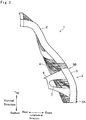
- Fig. 3 there is shown a side view of a seatback of the vehicle seat according to a first embodiment of the present application. It is to be noted that the vehicle seat according to the present application may be used not only as a driver's seat but also as a front passenger seat.
- the seatback 1 for supporting an occupant's back comprises a main frame 2 as a fixed frame, and a sub-frame 3 suspended from the main frame 2 in a pivotal manner
- a swivel-coupling and an outer periphery support (neither of which are shown) described in US2015/0367756 A1 may be used to allow the sub-frame 3 to swivel.
- both right upper corner and left upper corner of the sub-frame 3 are individually connected to the main frame 2 through the outer periphery support taught by US2015/0367756 A1 .
- the main frame 2 is situated at a level to support a shoulder blade of the occupant
- the sub-frame 3 is situated at a level to support a lumbosacral area of the occupant.
- the main frame 2 and the sub-frame 3 are curved along the back contour of the occupant from the shoulder to the hips.
- a net member 4 of predetermined pattern as a support member is attached to a face of the seatback 1 from the main frame 2 to the sub-frame 3.
- the net member 4 is formed of flexible and contractible warp threads and weft threads.
- a seat frame (not shown) is connected to the main frame 2 through a recliner mechanism (not shown), and a lower portion of the main frame 2 is slidably engaged with guiderails extending on a floor of a vehicle in a longitudinal direction.
- a headrest is attached to an upper portion of the main frame 2 to support a head of the occupant.
- Fig. 1 is a front view of the sub-frame 3 according to the first embodiment
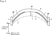
- Fig. 2 is a top view of the sub-frame 3 according to the first embodiment.
- the sub-frame 3 comprises a pair of lateral members 5 extending vertically on both right and left sides, and a reinforcement member 6 connecting the lateral members 5.
- the lateral members 5 are individually curved in the longitudinal direction of the vehicle along the contour of the lumbar spine of the occupant, and heights of the lateral members 5 are set in such a manner as to support the lumbar spine of the occupant.
- the reinforcement member 6 is a plate member or a band member extending between the lateral members 5, and the reinforcement member 6 is depressed upwardly and downwardly at a center portion 6A.
- a width of the reinforcement member 6 is gradually reduced from both right and left end portions 6B toward the center portion 6A.
- a semi-elliptical side hole 7 is individually formed from each of the end portion 6B toward the center portion 6A.
- each lower end portions 6B is individually joined to a vicinity of a lower end 5A of the lateral member 5, and each upper end portions 6B is individually joined to a vicinity of an upper end 5B of the lateral member 5.
- each lower end portions 6B of the reinforce member 6 is joined to the lateral member 5 at a portion slightly higher than the lower end 5A.
- the center portion 6A of the reinforcement member 6 is curved backwardly to be situated behind the lateral members 5 in a longitudinal direction of the vehicle. That is, a width center portion of the reinforcement member 6 is situated behind the lateral members 5 (with respect to the longitudinal direction of the vehicle).
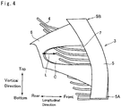
- Fig. 4 is an enlarged side view of the sub-frame 3 showing a portion of the net member 4 attached to sub-frame 3
- Fig. 5 is a partial front view of the net member 4 attached to sub-frame 3
- Fig. 6 is a partial rear view of the net member 4 attached to sub-frame 3.
- the warp threads of the net member 4 are omitted for the sake of illustration. As shown in Fig. 4 .
- a predetermined clearance C is maintained between the net member 4 and the reinforcement member 6, and a shortest distance L between the net member 4 and the reinforcement member 6 is determined experimentally in such a manner that the net member 4 pushed backwardly (with respect to the longitudinal direction of the vehicle) by the occupant will not be brought into contact to the reinforcement member 6 even in the event of a rear-end collision.
- the sub-frame 3 is subjected to a deformation load resulting from a weight shift of the driver.
- the reinforcement member 6 serves as a pair of crossing diagonal beams supporting the lateral members 5 at the lower ends 5A and the upper ends 5B, rigidity or strength of the sub-frame 3 can be enhanced to prevent deformation of the sub-frame 3.
- the rigidity of the lower portion of the sub-frame 3 holding the lumbosacral area of the driver is enhanced, the sub-frame 3 is allowed to swivel accurately in accordance with the twisting motion of the driver.
- Fig. 7 there is shown a front view of the sub-frame 3 according to a second embodiment.
- an elliptical center hole 7' is formed on the center portion 6A of the reinforcement member 6 in addition to the side holes 7.
- the remaining structures are similar to those of the sub-frame 3 shown in Figs. 1 to 6 , and detailed explanations for the common elements will be omitted by allotting common reference numerals thereto.
- the sub-frame 3 may be further lightened and a manufacturing cost may be reduced in addition to the above-explained advantages of the first embodiment.
- Fig. 8 shows a front view of the sub-frame 3 according to a third embodiment.
- the reinforcement member 6 comprises a pair of horizontal beams 8 extending parallel to each other between the lateral members 5 and a vertical beam 9 connecting center portions of the horizontal beams 8.
- each end portions of the lower horizontal beam 8 is individually joined to the vicinity of the lower end 5A of the lateral member 5, and each end portion of the upper horizontal beam 8 is individually joined to the vicinity of the upper end 5B of the lateral member 5.
- each of the side holes 7 is individually enlarged so that the sub-frame 3 may be further lightened and a manufacturing may be further reduced in addition to the above-explained advantages of the foregoing embodiments.
- Fig. 9 shows a front view of the sub-frame 3 according to a fourth embodiment.
- the reinforcement member 6 comprises a first diagonal beam 10 extending between the lower end 5A of one of the lateral members 5 and the upper end 5B of the other lateral member 5, and a second diagonal beam 11 extending between the lower end 5A of said other lateral member 5 and the upper end 5B of said one of the lateral members 5.
- the first diagonal beam 10 and the second diagonal beam 11 may be integrated at an intersection point.
- a structure of the sub-frame 3 may be simplified in addition to the above-explained advantages of the foregoing embodiments.
- Fig. 10 shows a front view of the sub-frame 3 according to a fifth embodiment.
- neither the side holes 7 nor the center hole 7' are formed on the reinforcement member 6, and both right and left end portions 6B of the reinforcement member 6 are joined entirely to the lateral members 5 from the vicinity of the lower end 5A to the vicinity of an upper end 5B. That is, lateral faces of the reinforcement member 6 are totally contacted to the lateral members 5.
- the center portion 6A of the reinforcement member 6 is also depressed upwardly and downwardly. In other words, a width of the reinforcement member 6 is also gradually reduced from both right and left end portions 6B toward the center portion 6A. According to the fifth embodiment, therefore, rigidity of the sub-frame 3 may be further enhanced to prevent deformation.
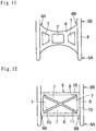
- Fig. 11 shows a front view of the sub-frame 3 according to a sixth embodiment.
- a rectangular center hole 7' is formed on the center portion 6A, and trapezoidal side holes 7 are formed on both sides of the rectangular center hole 7'.
- Each trapezoidal side hole 7 comprises two parallel faces and two inclined faces, the shortest of the parallel faces being the closest to the rectangular center hole 7'.
- the reinforcement member 6 may be lightened while reducing a manufacturing cost.
- rigidity of the sub-frame 3 may also be enhanced to prevent deformation.
- Fig. 12 shows a front view of the sub-frame 3 according to a seventh embodiment in which the reinforcement member 6 is formed into a rectangular shape.
- the reinforcement member 6 comprises a pair of horizontal beams 8, a pair of vertical beams 13, and a pair of first diagonal beam 10 and second diagonal beam 11. Both right and left end portions 6B of the vertical beams 13 are also joined entirely to the lateral members 5, and upper ends of the vertical beams 13 and lower ends of the vertical beams 13 are connected through the horizontal beams 8 extending parallel to each other.
- the first diagonal beam 10 extends between the lower end 5A of one of the lateral members 5 and the upper end 5B of the other lateral member 5, and the second diagonal beam 11 extending between the lower end 5A of said other lateral member 5 and the upper end 5B of said one of the lateral members 5.
- all of the holes 7 may be enlarged so as to further lighten the reinforcement member 6 and to further save a manufacturing cost.
- rigidity of the sub-frame 3 may also be enhanced to prevent deformation.
- the reinforcement member 6 In order to lighten the reinforcement member 6 while ensuring rigidity thereof, for example, fiber-glass reinforced plastic, fiber-reinforced composite material or the like may be used to form the reinforcement member 6, and the reinforcement member 6 may be manufactured suitably by an injection moluding method. Specifically, the reinforcement member 6 may be manufactured by setting predetermined fiber material and closing a mould, and thereafter injecting synthetic resin material into the mould.
Landscapes
- Engineering & Computer Science (AREA)
- Aviation & Aerospace Engineering (AREA)
- Transportation (AREA)
- Mechanical Engineering (AREA)
- Seats For Vehicles (AREA)
Abstract
Description
- The present application claims the benefit of priority to
Japanese Patent Application No. 2016-052312 filed on March 16, 2016 - Embodiments of the present application relate to a vehicle seat in which a backrest is partially allowed to kinetically swivel with movement of an occupant
- One example of the vehicle seat of this kind is described in
US2015/0367756 A1 . According to the teachings ofUS2015/0367756 A1 , a rectangular sub-frame of a backrest section includes a pair of left and right side sections extending vertically, and a lower section connecting lower portions of the side sections. The backrest section is suspended from a seatback frame through a suspension section while being allowed to swivel with respect to the seatback frame. -
PCT international publication WO 2013/021497 also describes the vehicle seat of this kind. The vehicle seat taught byWO 2013/021497 , a seat frame includes a first seat frame attached to a rail so as to be slidable and arranged parallel to a floor of the vehicle, and a second seat frame attached to the first seat frame through a reclining mechanism. A seat backrest is attached to thesecond seat frame 5 through a thrust bearing so that the seat backrest is allowed to rotate in the roll direction. - In the vehicle seat taught by
US2015/0367756 A1 , a net member attached to the seatback is formed of flexible and contractible material to be stretched by a longitudinal motion of a back of the occupant, and the lower section of the sub-frame is formed into an inverted U-shape at a level lower than the lumbosacral area of an occupant to allow the occupant to lean against the seatback. The sub-frame is oscillated laterally in accordance with a turning motion of the vehicle or a lateral weight shift of the occupant. However, since the lower section is merely connecting the side sections while being retracted, the sub-frame may be deformed by a diagonal load resulting from the oscillating motion thereof. Such deformation of the sub-frame may be prevented by increasing thicknesses of the side sections and the lower section to enhance strengths of those members. In this case, however, a total weight of the vehicle seat may be increased as a result of such beef-up of the sub-frame. Such increase in the weight of the vehicle seat may be prevented using lightweight material of high rigidity. In this case, a manufacturing cost of the vehicle seat may be increased. In the vehicle seat taught byWO 2013/021497 , the seat backrest may also be deformed by a diagonal load resulting from pivotal motion thereof. - Aspects of the present application have been conceived noting the foregoing technical problems, and it is therefore an object of the present application is to provide a vehicle seat having a swivelable sub-frame with enhanced rigidity.
- The present application relates to a vehicle seat having a seatback including a main frame and a sub-frame suspended from the main frame while being allowed to swivel. In order to achieve the above-explained objective, according to embodiments of the present application, the sub-frame is provided with a pair of lateral members extending vertically on both right and left sides of the sub-frame, and a reinforcement member connecting the lateral members. Specifically, the reinforcement member is situated behind the lateral members in a longitudinal direction of the vehicle. In the following description, the longitudinal direction of the vehicle will be considered as the horizontal direction which goes from the rear of the vehicle to the front of the vehicle, while the vertical direction is perpendicular to this horizontal plane, i.e. from the bottom to the top of the vehicle. In the present description, "rear", "behind", or "front" refer to positions or direction seen with respect to the longitudinal direction. The backward direction is the direction that goes from the front of the vehicle towards the back of the vehicle.
- In a non-limiting embodiment, the reinforcement member may includes a plate member curved backwardly in which both lateral ends are joined to the lateral members at a plurality of points.
- In a non-limiting embodiment, the sub-frame may be situated at a level to support a lumbosacral area of an occupant, and the reinforcement member may be joined to the lateral members at a plurality of points higher than lower ends of the lateral members.
- In a non-limiting embodiment, the vehicle seat may further comprises a support member that is attached to the lateral members of the sub-frame to support the lumbosacral area of the occupant. In addition, a predetermined clearance is maintained between the support member and the reinforcement member.
- Thus, according to the embodiment of the present application, the lateral members of the sub-frame are connected through the reinforcement member. According to the embodiment, therefore, rigidity of the sub-frame may be enhanced to prevent deformation of the sub-frame swayed with a twisting motion of an occupant. In addition, since the reinforcement member is situated behind the lateral members, a conflict between a lumbar spine of the occupant and the reinforcement member can be prevented to improve comfort.
- Features, aspects, and advantages of exemplary embodiments of the present disclosure will become better understood with reference to the following description and accompanying drawings, which should not limit the disclosure in any way.
-
Fig. 1 is a front view of the sub-frame according to a first embodiment; -
Fig. 2 is a top view of the sub-frame according to the first embodiment; -
Fig. 3 is a side view of the sub-frame according to the first embodiment; -
Fig. 4 is a partial side view of the sub-frame according to the first embodiment to which a net member is attached; -
Fig. 5 is a front view of the net member attached to the sub-frame according to the first embodiment; -
Fig. 6 is a rear view of the net member attached to the sub-frame according to the first embodiment; -
Fig. 7 is a front view of the sub-frame according to a second embodiment; -
Fig. 8 is a front view of the sub-frame according to a third embodiment; -
Fig. 9 is a front view of the sub-frame according to a fourth embodiment; -
Fig. 10 is a front view of the sub-frame according to a fifth embodiment; -
Fig. 11 is a front view of the sub-frame according to a sixth embodiment; and -
Fig. 12 is a front view of the sub-frame according to a seventh embodiment. - Embodiments of the present application will now be explained with reference to the accompanying drawings. Turning now to
Fig. 3 , there is shown a side view of a seatback of the vehicle seat according to a first embodiment of the present application. It is to be noted that the vehicle seat according to the present application may be used not only as a driver's seat but also as a front passenger seat. Theseatback 1 for supporting an occupant's back comprises amain frame 2 as a fixed frame, and asub-frame 3 suspended from themain frame 2 in a pivotal manner For example, a swivel-coupling and an outer periphery support (neither of which are shown) described inUS2015/0367756 A1 may be used to allow thesub-frame 3 to swivel. Specifically, both right upper corner and left upper corner of thesub-frame 3 are individually connected to themain frame 2 through the outer periphery support taught byUS2015/0367756 A1 . - In the
seatback 1, specifically, themain frame 2 is situated at a level to support a shoulder blade of the occupant, and thesub-frame 3 is situated at a level to support a lumbosacral area of the occupant. As depicted inFig. 3 , themain frame 2 and thesub-frame 3 are curved along the back contour of the occupant from the shoulder to the hips. - A
net member 4 of predetermined pattern as a support member is attached to a face of theseatback 1 from themain frame 2 to thesub-frame 3. In order to flexibly support the shoulder blade and the lumbar spine of the occupant, thenet member 4 is formed of flexible and contractible warp threads and weft threads. A seat frame (not shown) is connected to themain frame 2 through a recliner mechanism (not shown), and a lower portion of themain frame 2 is slidably engaged with guiderails extending on a floor of a vehicle in a longitudinal direction. In addition, a headrest is attached to an upper portion of themain frame 2 to support a head of the occupant. -
Fig. 1 is a front view of thesub-frame 3 according to the first embodiment, andFig. 2 is a top view of thesub-frame 3 according to the first embodiment. As illustrated inFigs. 1 and2 , thesub-frame 3 comprises a pair oflateral members 5 extending vertically on both right and left sides, and areinforcement member 6 connecting thelateral members 5. Thelateral members 5 are individually curved in the longitudinal direction of the vehicle along the contour of the lumbar spine of the occupant, and heights of thelateral members 5 are set in such a manner as to support the lumbar spine of the occupant. - As illustrated in
Fig. 1 , thereinforcement member 6 is a plate member or a band member extending between thelateral members 5, and thereinforcement member 6 is depressed upwardly and downwardly at acenter portion 6A. In other words, a width of thereinforcement member 6 is gradually reduced from both right andleft end portions 6B toward thecenter portion 6A. In addition, asemi-elliptical side hole 7 is individually formed from each of theend portion 6B toward thecenter portion 6A. In thereinforcement member 6 thus shaped into an X-shape, eachlower end portions 6B is individually joined to a vicinity of alower end 5A of thelateral member 5, and eachupper end portions 6B is individually joined to a vicinity of anupper end 5B of thelateral member 5. Specifically, eachlower end portions 6B of the reinforcemember 6 is joined to thelateral member 5 at a portion slightly higher than thelower end 5A. As illustrated inFig. 2 , thecenter portion 6A of thereinforcement member 6 is curved backwardly to be situated behind thelateral members 5 in a longitudinal direction of the vehicle. That is, a width center portion of thereinforcement member 6 is situated behind the lateral members 5 (with respect to the longitudinal direction of the vehicle). -
Fig. 4 is an enlarged side view of thesub-frame 3 showing a portion of thenet member 4 attached tosub-frame 3,Fig. 5 is a partial front view of thenet member 4 attached tosub-frame 3, andFig. 6 is a partial rear view of thenet member 4 attached tosub-frame 3. InFigs. 4 to 6 , the warp threads of thenet member 4 are omitted for the sake of illustration. As shown inFig. 4 . A predetermined clearance C is maintained between thenet member 4 and thereinforcement member 6, and a shortest distance L between thenet member 4 and thereinforcement member 6 is determined experimentally in such a manner that thenet member 4 pushed backwardly (with respect to the longitudinal direction of the vehicle) by the occupant will not be brought into contact to thereinforcement member 6 even in the event of a rear-end collision. - For example, when a driver sitting on the vehicle seat according to the embodiments turns a steering wheel, a chest of the driver is twisted and the
sub-frame 3 is swayed by such twisting motion of the driver. In this situation, thesub-frame 3 is subjected to a deformation load resulting from a weight shift of the driver. However, since thereinforcement member 6 serves as a pair of crossing diagonal beams supporting thelateral members 5 at the lower ends 5A and the upper ends 5B, rigidity or strength of thesub-frame 3 can be enhanced to prevent deformation of thesub-frame 3. In addition, since the rigidity of the lower portion of thesub-frame 3 holding the lumbosacral area of the driver is enhanced, thesub-frame 3 is allowed to swivel accurately in accordance with the twisting motion of the driver. - In addition, since the clearance C is maintained between the
net member 4 and thereinforcement member 6, a conflict between the lumbar spine of the occupant and thereinforcement member 6 can be prevented to improve comfort. Further, since thenet member 4 will not be brought into contact to thereinforcement member 6 in the event of a rear-end collision, safety of the passenger can be ensured. Furthermore, if a child safety seat is installed on a back seat, the occupant of a front seat can be protected by thereinforcement member 6 from the child safety seat colliding against thereinforcement member 6 from behind in the event of a rear-end collision. - Turning to
Fig. 7 , there is shown a front view of thesub-frame 3 according to a second embodiment. According to the second embodiment, an elliptical center hole 7' is formed on thecenter portion 6A of thereinforcement member 6 in addition to the side holes 7. The remaining structures are similar to those of thesub-frame 3 shown inFigs. 1 to 6 , and detailed explanations for the common elements will be omitted by allotting common reference numerals thereto. According to the second embodiment, thesub-frame 3 may be further lightened and a manufacturing cost may be reduced in addition to the above-explained advantages of the first embodiment. -
Fig. 8 shows a front view of thesub-frame 3 according to a third embodiment. According to the third embodiment, thereinforcement member 6 comprises a pair ofhorizontal beams 8 extending parallel to each other between thelateral members 5 and a vertical beam 9 connecting center portions of thehorizontal beams 8. According the third embodiment, each end portions of the lowerhorizontal beam 8 is individually joined to the vicinity of thelower end 5A of thelateral member 5, and each end portion of the upperhorizontal beam 8 is individually joined to the vicinity of theupper end 5B of thelateral member 5. In this case, each of the side holes 7 is individually enlarged so that thesub-frame 3 may be further lightened and a manufacturing may be further reduced in addition to the above-explained advantages of the foregoing embodiments. -
Fig. 9 shows a front view of thesub-frame 3 according to a fourth embodiment. According to the fourth embodiment, thereinforcement member 6 comprises a firstdiagonal beam 10 extending between thelower end 5A of one of thelateral members 5 and theupper end 5B of the otherlateral member 5, and a seconddiagonal beam 11 extending between thelower end 5A of said otherlateral member 5 and theupper end 5B of said one of thelateral members 5. The firstdiagonal beam 10 and the seconddiagonal beam 11 may be integrated at an intersection point. In this case, a structure of thesub-frame 3 may be simplified in addition to the above-explained advantages of the foregoing embodiments. -
Fig. 10 shows a front view of thesub-frame 3 according to a fifth embodiment. According to the fifth embodiment, neither the side holes 7 nor the center hole 7' are formed on thereinforcement member 6, and both right andleft end portions 6B of thereinforcement member 6 are joined entirely to thelateral members 5 from the vicinity of thelower end 5A to the vicinity of anupper end 5B. That is, lateral faces of thereinforcement member 6 are totally contacted to thelateral members 5. Thecenter portion 6A of thereinforcement member 6 is also depressed upwardly and downwardly. In other words, a width of thereinforcement member 6 is also gradually reduced from both right andleft end portions 6B toward thecenter portion 6A. According to the fifth embodiment, therefore, rigidity of thesub-frame 3 may be further enhanced to prevent deformation. -
Fig. 11 shows a front view of thesub-frame 3 according to a sixth embodiment. In thereinforcement member 6 according to the sixth embodiment, a rectangular center hole 7' is formed on thecenter portion 6A, and trapezoidal side holes 7 are formed on both sides of the rectangular center hole 7'. Eachtrapezoidal side hole 7 comprises two parallel faces and two inclined faces, the shortest of the parallel faces being the closest to the rectangular center hole 7'. According to the sixth embodiment, thereinforcement member 6 may be lightened while reducing a manufacturing cost. In addition, since the right andleft end portions 6B of thereinforcement member 6 are also joined entirely to thelateral members 5, rigidity of thesub-frame 3 may also be enhanced to prevent deformation. -
Fig. 12 shows a front view of thesub-frame 3 according to a seventh embodiment in which thereinforcement member 6 is formed into a rectangular shape. According to the seventh embodiment, thereinforcement member 6 comprises a pair ofhorizontal beams 8, a pair ofvertical beams 13, and a pair of firstdiagonal beam 10 and seconddiagonal beam 11. Both right andleft end portions 6B of thevertical beams 13 are also joined entirely to thelateral members 5, and upper ends of thevertical beams 13 and lower ends of thevertical beams 13 are connected through thehorizontal beams 8 extending parallel to each other. The firstdiagonal beam 10 extends between thelower end 5A of one of thelateral members 5 and theupper end 5B of the otherlateral member 5, and the seconddiagonal beam 11 extending between thelower end 5A of said otherlateral member 5 and theupper end 5B of said one of thelateral members 5. According to the seventh embodiment, therefore, all of theholes 7 may be enlarged so as to further lighten thereinforcement member 6 and to further save a manufacturing cost. In addition, since the right andleft end portions 6B of thereinforcement member 6 are also joined entirely to thelateral members 5, rigidity of thesub-frame 3 may also be enhanced to prevent deformation. - In order to lighten the
reinforcement member 6 while ensuring rigidity thereof, for example, fiber-glass reinforced plastic, fiber-reinforced composite material or the like may be used to form thereinforcement member 6, and thereinforcement member 6 may be manufactured suitably by an injection moluding method. Specifically, thereinforcement member 6 may be manufactured by setting predetermined fiber material and closing a mould, and thereafter injecting synthetic resin material into the mould. - Although the above exemplary embodiments of the present application have been described, it will be understood by those skilled in the art that the present application should not be limited to the described exemplary embodiments, and various changes and modifications can be made within the scope of the present application.
Claims (4)
- A vehicle seat having a seatback (1) including a main frame (2) and a sub-frame (3) suspended from the main frame (2), said sub-frame (3) being configured to be able to swivel with respect to the main frame (2),
characterized in that:the sub-frame (3) includes a pair of lateral members (5) extending vertically on both right and left sides of the sub-frame (3), and a reinforcement member (6) connecting the lateral members (5); andthe reinforcement member (6) is situated behind the lateral members (5) in a longitudinal direction of the vehicle. - The vehicle seat as claimed in claim 1, wherein the reinforcement member (6) includes a plate member curved backwardly with respect to the longitudinal direction of the vehicle, and in which both lateral ends are joined to the lateral members (5) at a plurality of points.
- The vehicle seat as claimed in claim 1 or 2,
wherein the sub-frame (3) is situated at a level to support a lumbosacral area of an occupant, and
wherein the reinforcement member (6) is joined to the lateral members (5) at a plurality of points that are higher than lower ends (5A) of the lateral members (5) along a vertical direction of the vehicle. - The vehicle seat as claimed in any of claims 1 to 3, comprising:a support member that is attached to the lateral members (5) of the sub-frame (3) to support the lumbosacral area of the occupant;wherein a predetermined clearance (C) is maintained between the support member and the reinforcement member (6).
Applications Claiming Priority (1)
| Application Number | Priority Date | Filing Date | Title |
|---|---|---|---|
| JP2016052312A JP6455471B2 (en) | 2016-03-16 | 2016-03-16 | Vehicle seat |
Publications (2)
| Publication Number | Publication Date |
|---|---|
| EP3219538A1 true EP3219538A1 (en) | 2017-09-20 |
| EP3219538B1 EP3219538B1 (en) | 2019-04-24 |
Family
ID=58265916
Family Applications (1)
| Application Number | Title | Priority Date | Filing Date |
|---|---|---|---|
| EP17160185.9A Active EP3219538B1 (en) | 2016-03-16 | 2017-03-09 | Vehicle seat |
Country Status (3)
| Country | Link |
|---|---|
| US (1) | US10793034B2 (en) |
| EP (1) | EP3219538B1 (en) |
| JP (1) | JP6455471B2 (en) |
Citations (3)
| Publication number | Priority date | Publication date | Assignee | Title |
|---|---|---|---|---|
| WO2013021497A1 (en) | 2011-08-10 | 2013-02-14 | トヨタ自動車株式会社 | Vehicle seat apparatus |
| US20130076092A1 (en) * | 2011-09-26 | 2013-03-28 | Faurecia Automotive Seating, Llc | Vehicle seat backrest with flexural joint motion-control |
| US20150367756A1 (en) | 2014-06-20 | 2015-12-24 | Toyota Jidosha Kabushiki Kaisha | Vehicle seat |
Family Cites Families (35)
| Publication number | Priority date | Publication date | Assignee | Title |
|---|---|---|---|---|
| FR1216435A (en) * | 1958-11-25 | 1960-04-25 | Grosfillex Freres | Shaped article of plastics suitable for use in particular as a removable seat and backrest for chairs and the like |
| DE2064419C3 (en) * | 1970-12-30 | 1979-08-30 | Recaro Gmbh & Co, 7000 Stuttgart | Backrests for automobile seats |
| US4157203A (en) * | 1977-05-09 | 1979-06-05 | Center For Design Research And Development N.V. | Articulated double back for chairs |
| USD274771S (en) * | 1980-10-06 | 1984-07-24 | Center For Design Research And Development Nv | Chair |
| KR100334316B1 (en) * | 1992-06-15 | 2002-10-11 | 헤르만밀러인코퍼레이티드 | Supporting device and manufacturing method of office suspect |
| US5447360A (en) * | 1993-09-30 | 1995-09-05 | Hoover Universal, Inc. | Side impact seat back structure |
| US5513897A (en) * | 1994-02-22 | 1996-05-07 | Lemmen; Roger D. | Vehicle seat |
| USD401794S (en) * | 1996-04-24 | 1998-12-01 | Center For Design Research And Development N.V. | Chair seat and back |
| JP3325783B2 (en) * | 1996-10-09 | 2002-09-17 | センター フォア デザイン リサーチ アンド ディベロプメント ナームローゼフェンノートチャップ | Adjustable chair |
| JP3874392B2 (en) | 1998-07-09 | 2007-01-31 | 株式会社岡村製作所 | Chair |
| JP4250128B2 (en) * | 2003-09-29 | 2009-04-08 | 株式会社豊田中央研究所 | Sheet |
| US20050127735A1 (en) * | 2003-11-03 | 2005-06-16 | Kenneth Munsch | Vehicle seat with adjustable support system |
| CA2491299A1 (en) * | 2004-12-20 | 2006-06-20 | Baultar I.D. Inc. | Adjustable backrest for ergonomic seat |
| USD534384S1 (en) * | 2005-04-07 | 2007-01-02 | Tung-Hua Su | Backrest for a chair |
| JP5002835B2 (en) * | 2005-10-27 | 2012-08-15 | コクヨ株式会社 | Member connection structure |
| EP2004018A4 (en) * | 2006-03-27 | 2011-09-14 | C Pod Ergonomics Pty Ltd | A back support adjustment system |
| JP4957416B2 (en) * | 2007-07-05 | 2012-06-20 | アイシン精機株式会社 | Vehicle seat device |
| US20110133531A1 (en) * | 2009-12-09 | 2011-06-09 | Yeh Chia-Chang | Seat applicable to vehicles |
| US8109576B2 (en) * | 2010-01-25 | 2012-02-07 | Uei Yuang Enterprise Co., Ltd. | Seat assembly |
| JP5634890B2 (en) | 2011-01-17 | 2014-12-03 | カリモク家具株式会社 | Chair |
| JP5316557B2 (en) * | 2011-02-02 | 2013-10-16 | アイシン精機株式会社 | Seat adjustment device and vehicle seat device provided with the seat adjustment device |
| DE102011055895A1 (en) * | 2011-11-30 | 2013-06-06 | Grammer Ag | Vehicle seat with lateral support element |
| EP2599659B1 (en) * | 2011-11-30 | 2016-09-14 | Grammer Ag | Vehicle seat and commercial vehicle |
| JP5598557B2 (en) * | 2013-01-10 | 2014-10-01 | トヨタ自動車株式会社 | Vehicle seat device |
| US9096157B2 (en) * | 2013-01-24 | 2015-08-04 | Ford Global Technologies, Llc | Seating assembly with air distribution system |
| US9415713B2 (en) * | 2013-01-24 | 2016-08-16 | Ford Global Technologies, Llc | Flexible seatback system |
| CN105531147B (en) * | 2013-07-24 | 2017-11-03 | 丰田自动车株式会社 | seat |
| JP6070601B2 (en) * | 2014-02-26 | 2017-02-01 | トヨタ自動車株式会社 | Vehicle seat |
| JP6160530B2 (en) * | 2014-03-24 | 2017-07-12 | トヨタ自動車株式会社 | Vehicle seat |
| US10173567B2 (en) * | 2014-06-16 | 2019-01-08 | Zodiac Seats Us Llc | Lightweight headrests with suspension mesh and supporting frame |
| US9789790B2 (en) * | 2014-10-03 | 2017-10-17 | Ford Global Technologies, Llc | Tuned flexible support member and flexible suspension features for comfort carriers |
| JP6096744B2 (en) * | 2014-11-04 | 2017-03-15 | 本田技研工業株式会社 | Vehicle seat |
| JP6398797B2 (en) * | 2015-03-05 | 2018-10-03 | トヨタ紡織株式会社 | Vehicle seat |
| JP6512189B2 (en) * | 2016-07-25 | 2019-05-15 | トヨタ自動車株式会社 | Vehicle seat |
| JP6512196B2 (en) * | 2016-09-15 | 2019-05-15 | トヨタ自動車株式会社 | Vehicle seat |
-
2016
- 2016-03-16 JP JP2016052312A patent/JP6455471B2/en active Active
-
2017
- 2017-03-09 EP EP17160185.9A patent/EP3219538B1/en active Active
- 2017-03-15 US US15/460,208 patent/US10793034B2/en active Active
Patent Citations (3)
| Publication number | Priority date | Publication date | Assignee | Title |
|---|---|---|---|---|
| WO2013021497A1 (en) | 2011-08-10 | 2013-02-14 | トヨタ自動車株式会社 | Vehicle seat apparatus |
| US20130076092A1 (en) * | 2011-09-26 | 2013-03-28 | Faurecia Automotive Seating, Llc | Vehicle seat backrest with flexural joint motion-control |
| US20150367756A1 (en) | 2014-06-20 | 2015-12-24 | Toyota Jidosha Kabushiki Kaisha | Vehicle seat |
Also Published As
| Publication number | Publication date |
|---|---|
| JP2017165255A (en) | 2017-09-21 |
| JP6455471B2 (en) | 2019-01-23 |
| US10793034B2 (en) | 2020-10-06 |
| EP3219538B1 (en) | 2019-04-24 |
| US20170267144A1 (en) | 2017-09-21 |
Similar Documents
| Publication | Publication Date | Title |
|---|---|---|
| CN104010877B (en) | Backrest frame structure | |
| US10202053B2 (en) | Vehicle seat | |
| JP6619012B2 (en) | Backrest and seat including it | |
| US9783091B2 (en) | Seatback frame and resin for employing in a seatback frame | |
| US10272809B2 (en) | Vehicle seat | |
| JP6015717B2 (en) | Vehicle seat | |
| US9849814B2 (en) | Vehicle seat | |
| CN104024046B (en) | Seat backrest frame structure | |
| WO2012077764A1 (en) | Vehicle seat | |
| CN104661871A (en) | Vehicle seat | |
| CN104144820A (en) | vehicle seat | |
| US9815391B2 (en) | Vehicle seat with side pieces made of autoreactive framework structures | |
| EP3219538B1 (en) | Vehicle seat | |
| US9663009B2 (en) | Conveyance seat | |
| US20160288683A1 (en) | Seat frame | |
| JP2016052820A (en) | Rear seat back frame structure | |
| JP2017109628A (en) | Rear seat support structure for vehicle | |
| JP7203802B2 (en) | vehicle seat | |
| KR101536146B1 (en) | Lightweight seat back frame | |
| CN207737147U (en) | Lower armchair structure | |
| JP2024023124A (en) | vehicle seat | |
| WO2017171663A1 (en) | Vehicle seat wire structure and vehicle seat | |
| JP2014080049A (en) | Vehicle seat |
Legal Events
| Date | Code | Title | Description |
|---|---|---|---|
| PUAI | Public reference made under article 153(3) epc to a published international application that has entered the european phase |
Free format text: ORIGINAL CODE: 0009012 |
|
| STAA | Information on the status of an ep patent application or granted ep patent |
Free format text: STATUS: REQUEST FOR EXAMINATION WAS MADE |
|
| 17P | Request for examination filed |
Effective date: 20170309 |
|
| AK | Designated contracting states |
Kind code of ref document: A1 Designated state(s): AL AT BE BG CH CY CZ DE DK EE ES FI FR GB GR HR HU IE IS IT LI LT LU LV MC MK MT NL NO PL PT RO RS SE SI SK SM TR |
|
| AX | Request for extension of the european patent |
Extension state: BA ME |
|
| RIC1 | Information provided on ipc code assigned before grant |
Ipc: B60N 2/68 20060101ALI20180927BHEP Ipc: B60N 2/70 20060101ALI20180927BHEP Ipc: B60N 2/66 20060101ALI20180927BHEP Ipc: B60N 2/64 20060101AFI20180927BHEP |
|
| GRAP | Despatch of communication of intention to grant a patent |
Free format text: ORIGINAL CODE: EPIDOSNIGR1 |
|
| STAA | Information on the status of an ep patent application or granted ep patent |
Free format text: STATUS: GRANT OF PATENT IS INTENDED |
|
| INTG | Intention to grant announced |
Effective date: 20181210 |
|
| GRAS | Grant fee paid |
Free format text: ORIGINAL CODE: EPIDOSNIGR3 |
|
| GRAA | (expected) grant |
Free format text: ORIGINAL CODE: 0009210 |
|
| STAA | Information on the status of an ep patent application or granted ep patent |
Free format text: STATUS: THE PATENT HAS BEEN GRANTED |
|
| AK | Designated contracting states |
Kind code of ref document: B1 Designated state(s): AL AT BE BG CH CY CZ DE DK EE ES FI FR GB GR HR HU IE IS IT LI LT LU LV MC MK MT NL NO PL PT RO RS SE SI SK SM TR |
|
| REG | Reference to a national code |
Ref country code: GB Ref legal event code: FG4D |
|
| REG | Reference to a national code |
Ref country code: CH Ref legal event code: EP |
|
| REG | Reference to a national code |
Ref country code: AT Ref legal event code: REF Ref document number: 1123734 Country of ref document: AT Kind code of ref document: T Effective date: 20190515 Ref country code: IE Ref legal event code: FG4D |
|
| REG | Reference to a national code |
Ref country code: DE Ref legal event code: R096 Ref document number: 602017003417 Country of ref document: DE |
|
| REG | Reference to a national code |
Ref country code: DE Ref legal event code: R084 Ref document number: 602017003417 Country of ref document: DE |
|
| REG | Reference to a national code |
Ref country code: GB Ref legal event code: 746 Effective date: 20190716 |
|
| REG | Reference to a national code |
Ref country code: NL Ref legal event code: MP Effective date: 20190424 |
|
| REG | Reference to a national code |
Ref country code: LT Ref legal event code: MG4D |
|
| PG25 | Lapsed in a contracting state [announced via postgrant information from national office to epo] |
Ref country code: NL Free format text: LAPSE BECAUSE OF FAILURE TO SUBMIT A TRANSLATION OF THE DESCRIPTION OR TO PAY THE FEE WITHIN THE PRESCRIBED TIME-LIMIT Effective date: 20190424 |
|
| PG25 | Lapsed in a contracting state [announced via postgrant information from national office to epo] |
Ref country code: PT Free format text: LAPSE BECAUSE OF FAILURE TO SUBMIT A TRANSLATION OF THE DESCRIPTION OR TO PAY THE FEE WITHIN THE PRESCRIBED TIME-LIMIT Effective date: 20190824 Ref country code: AL Free format text: LAPSE BECAUSE OF FAILURE TO SUBMIT A TRANSLATION OF THE DESCRIPTION OR TO PAY THE FEE WITHIN THE PRESCRIBED TIME-LIMIT Effective date: 20190424 Ref country code: ES Free format text: LAPSE BECAUSE OF FAILURE TO SUBMIT A TRANSLATION OF THE DESCRIPTION OR TO PAY THE FEE WITHIN THE PRESCRIBED TIME-LIMIT Effective date: 20190424 Ref country code: LT Free format text: LAPSE BECAUSE OF FAILURE TO SUBMIT A TRANSLATION OF THE DESCRIPTION OR TO PAY THE FEE WITHIN THE PRESCRIBED TIME-LIMIT Effective date: 20190424 Ref country code: FI Free format text: LAPSE BECAUSE OF FAILURE TO SUBMIT A TRANSLATION OF THE DESCRIPTION OR TO PAY THE FEE WITHIN THE PRESCRIBED TIME-LIMIT Effective date: 20190424 Ref country code: NO Free format text: LAPSE BECAUSE OF FAILURE TO SUBMIT A TRANSLATION OF THE DESCRIPTION OR TO PAY THE FEE WITHIN THE PRESCRIBED TIME-LIMIT Effective date: 20190724 Ref country code: HR Free format text: LAPSE BECAUSE OF FAILURE TO SUBMIT A TRANSLATION OF THE DESCRIPTION OR TO PAY THE FEE WITHIN THE PRESCRIBED TIME-LIMIT Effective date: 20190424 Ref country code: SE Free format text: LAPSE BECAUSE OF FAILURE TO SUBMIT A TRANSLATION OF THE DESCRIPTION OR TO PAY THE FEE WITHIN THE PRESCRIBED TIME-LIMIT Effective date: 20190424 |
|
| PG25 | Lapsed in a contracting state [announced via postgrant information from national office to epo] |
Ref country code: PL Free format text: LAPSE BECAUSE OF FAILURE TO SUBMIT A TRANSLATION OF THE DESCRIPTION OR TO PAY THE FEE WITHIN THE PRESCRIBED TIME-LIMIT Effective date: 20190424 Ref country code: RS Free format text: LAPSE BECAUSE OF FAILURE TO SUBMIT A TRANSLATION OF THE DESCRIPTION OR TO PAY THE FEE WITHIN THE PRESCRIBED TIME-LIMIT Effective date: 20190424 Ref country code: LV Free format text: LAPSE BECAUSE OF FAILURE TO SUBMIT A TRANSLATION OF THE DESCRIPTION OR TO PAY THE FEE WITHIN THE PRESCRIBED TIME-LIMIT Effective date: 20190424 Ref country code: GR Free format text: LAPSE BECAUSE OF FAILURE TO SUBMIT A TRANSLATION OF THE DESCRIPTION OR TO PAY THE FEE WITHIN THE PRESCRIBED TIME-LIMIT Effective date: 20190725 Ref country code: BG Free format text: LAPSE BECAUSE OF FAILURE TO SUBMIT A TRANSLATION OF THE DESCRIPTION OR TO PAY THE FEE WITHIN THE PRESCRIBED TIME-LIMIT Effective date: 20190724 |
|
| REG | Reference to a national code |
Ref country code: AT Ref legal event code: MK05 Ref document number: 1123734 Country of ref document: AT Kind code of ref document: T Effective date: 20190424 |
|
| PG25 | Lapsed in a contracting state [announced via postgrant information from national office to epo] |
Ref country code: IS Free format text: LAPSE BECAUSE OF FAILURE TO SUBMIT A TRANSLATION OF THE DESCRIPTION OR TO PAY THE FEE WITHIN THE PRESCRIBED TIME-LIMIT Effective date: 20190824 |
|
| REG | Reference to a national code |
Ref country code: DE Ref legal event code: R097 Ref document number: 602017003417 Country of ref document: DE |
|
| PG25 | Lapsed in a contracting state [announced via postgrant information from national office to epo] |
Ref country code: SK Free format text: LAPSE BECAUSE OF FAILURE TO SUBMIT A TRANSLATION OF THE DESCRIPTION OR TO PAY THE FEE WITHIN THE PRESCRIBED TIME-LIMIT Effective date: 20190424 Ref country code: CZ Free format text: LAPSE BECAUSE OF FAILURE TO SUBMIT A TRANSLATION OF THE DESCRIPTION OR TO PAY THE FEE WITHIN THE PRESCRIBED TIME-LIMIT Effective date: 20190424 Ref country code: RO Free format text: LAPSE BECAUSE OF FAILURE TO SUBMIT A TRANSLATION OF THE DESCRIPTION OR TO PAY THE FEE WITHIN THE PRESCRIBED TIME-LIMIT Effective date: 20190424 Ref country code: EE Free format text: LAPSE BECAUSE OF FAILURE TO SUBMIT A TRANSLATION OF THE DESCRIPTION OR TO PAY THE FEE WITHIN THE PRESCRIBED TIME-LIMIT Effective date: 20190424 Ref country code: AT Free format text: LAPSE BECAUSE OF FAILURE TO SUBMIT A TRANSLATION OF THE DESCRIPTION OR TO PAY THE FEE WITHIN THE PRESCRIBED TIME-LIMIT Effective date: 20190424 Ref country code: DK Free format text: LAPSE BECAUSE OF FAILURE TO SUBMIT A TRANSLATION OF THE DESCRIPTION OR TO PAY THE FEE WITHIN THE PRESCRIBED TIME-LIMIT Effective date: 20190424 |
|
| PG25 | Lapsed in a contracting state [announced via postgrant information from national office to epo] |
Ref country code: IT Free format text: LAPSE BECAUSE OF FAILURE TO SUBMIT A TRANSLATION OF THE DESCRIPTION OR TO PAY THE FEE WITHIN THE PRESCRIBED TIME-LIMIT Effective date: 20190424 Ref country code: SM Free format text: LAPSE BECAUSE OF FAILURE TO SUBMIT A TRANSLATION OF THE DESCRIPTION OR TO PAY THE FEE WITHIN THE PRESCRIBED TIME-LIMIT Effective date: 20190424 |
|
| PLBE | No opposition filed within time limit |
Free format text: ORIGINAL CODE: 0009261 |
|
| STAA | Information on the status of an ep patent application or granted ep patent |
Free format text: STATUS: NO OPPOSITION FILED WITHIN TIME LIMIT |
|
| PG25 | Lapsed in a contracting state [announced via postgrant information from national office to epo] |
Ref country code: TR Free format text: LAPSE BECAUSE OF FAILURE TO SUBMIT A TRANSLATION OF THE DESCRIPTION OR TO PAY THE FEE WITHIN THE PRESCRIBED TIME-LIMIT Effective date: 20190424 |
|
| 26N | No opposition filed |
Effective date: 20200127 |
|
| PG25 | Lapsed in a contracting state [announced via postgrant information from national office to epo] |
Ref country code: SI Free format text: LAPSE BECAUSE OF FAILURE TO SUBMIT A TRANSLATION OF THE DESCRIPTION OR TO PAY THE FEE WITHIN THE PRESCRIBED TIME-LIMIT Effective date: 20190424 |
|
| PG25 | Lapsed in a contracting state [announced via postgrant information from national office to epo] |
Ref country code: MC Free format text: LAPSE BECAUSE OF FAILURE TO SUBMIT A TRANSLATION OF THE DESCRIPTION OR TO PAY THE FEE WITHIN THE PRESCRIBED TIME-LIMIT Effective date: 20190424 |
|
| REG | Reference to a national code |
Ref country code: CH Ref legal event code: PL |
|
| REG | Reference to a national code |
Ref country code: BE Ref legal event code: MM Effective date: 20200331 |
|
| PG25 | Lapsed in a contracting state [announced via postgrant information from national office to epo] |
Ref country code: LU Free format text: LAPSE BECAUSE OF NON-PAYMENT OF DUE FEES Effective date: 20200309 |
|
| PG25 | Lapsed in a contracting state [announced via postgrant information from national office to epo] |
Ref country code: CH Free format text: LAPSE BECAUSE OF NON-PAYMENT OF DUE FEES Effective date: 20200331 Ref country code: LI Free format text: LAPSE BECAUSE OF NON-PAYMENT OF DUE FEES Effective date: 20200331 Ref country code: IE Free format text: LAPSE BECAUSE OF NON-PAYMENT OF DUE FEES Effective date: 20200309 |
|
| PG25 | Lapsed in a contracting state [announced via postgrant information from national office to epo] |
Ref country code: BE Free format text: LAPSE BECAUSE OF NON-PAYMENT OF DUE FEES Effective date: 20200331 |
|
| PGFP | Annual fee paid to national office [announced via postgrant information from national office to epo] |
Ref country code: FR Payment date: 20210210 Year of fee payment: 5 |
|
| PGFP | Annual fee paid to national office [announced via postgrant information from national office to epo] |
Ref country code: GB Payment date: 20210225 Year of fee payment: 5 |
|
| PGFP | Annual fee paid to national office [announced via postgrant information from national office to epo] |
Ref country code: DE Payment date: 20220203 Year of fee payment: 6 |
|
| PG25 | Lapsed in a contracting state [announced via postgrant information from national office to epo] |
Ref country code: MT Free format text: LAPSE BECAUSE OF FAILURE TO SUBMIT A TRANSLATION OF THE DESCRIPTION OR TO PAY THE FEE WITHIN THE PRESCRIBED TIME-LIMIT Effective date: 20190424 Ref country code: CY Free format text: LAPSE BECAUSE OF FAILURE TO SUBMIT A TRANSLATION OF THE DESCRIPTION OR TO PAY THE FEE WITHIN THE PRESCRIBED TIME-LIMIT Effective date: 20190424 |
|
| PG25 | Lapsed in a contracting state [announced via postgrant information from national office to epo] |
Ref country code: MK Free format text: LAPSE BECAUSE OF FAILURE TO SUBMIT A TRANSLATION OF THE DESCRIPTION OR TO PAY THE FEE WITHIN THE PRESCRIBED TIME-LIMIT Effective date: 20190424 |
|
| GBPC | Gb: european patent ceased through non-payment of renewal fee |
Effective date: 20220309 |
|
| PG25 | Lapsed in a contracting state [announced via postgrant information from national office to epo] |
Ref country code: GB Free format text: LAPSE BECAUSE OF NON-PAYMENT OF DUE FEES Effective date: 20220309 Ref country code: FR Free format text: LAPSE BECAUSE OF NON-PAYMENT OF DUE FEES Effective date: 20220331 |
|
| P01 | Opt-out of the competence of the unified patent court (upc) registered |
Effective date: 20230517 |
|
| REG | Reference to a national code |
Ref country code: DE Ref legal event code: R119 Ref document number: 602017003417 Country of ref document: DE |
|
| PG25 | Lapsed in a contracting state [announced via postgrant information from national office to epo] |
Ref country code: DE Free format text: LAPSE BECAUSE OF NON-PAYMENT OF DUE FEES Effective date: 20231003 |