EP3219431A1 - Method and device for processing cooling hole on workpiece with laser - Google Patents
Method and device for processing cooling hole on workpiece with laser Download PDFInfo
- Publication number
- EP3219431A1 EP3219431A1 EP14905737.4A EP14905737A EP3219431A1 EP 3219431 A1 EP3219431 A1 EP 3219431A1 EP 14905737 A EP14905737 A EP 14905737A EP 3219431 A1 EP3219431 A1 EP 3219431A1
- Authority
- EP
- European Patent Office
- Prior art keywords
- hole part
- processing
- shaped hole
- workpiece
- laser pulse
- Prior art date
- Legal status (The legal status is an assumption and is not a legal conclusion. Google has not performed a legal analysis and makes no representation as to the accuracy of the status listed.)
- Withdrawn
Links
Images



Classifications
-
- B—PERFORMING OPERATIONS; TRANSPORTING
- B23—MACHINE TOOLS; METAL-WORKING NOT OTHERWISE PROVIDED FOR
- B23K—SOLDERING OR UNSOLDERING; WELDING; CLADDING OR PLATING BY SOLDERING OR WELDING; CUTTING BY APPLYING HEAT LOCALLY, e.g. FLAME CUTTING; WORKING BY LASER BEAM
- B23K26/00—Working by laser beam, e.g. welding, cutting or boring
- B23K26/36—Removing material
- B23K26/38—Removing material by boring or cutting
- B23K26/382—Removing material by boring or cutting by boring
- B23K26/384—Removing material by boring or cutting by boring of specially shaped holes
-
- B—PERFORMING OPERATIONS; TRANSPORTING
- B23—MACHINE TOOLS; METAL-WORKING NOT OTHERWISE PROVIDED FOR
- B23K—SOLDERING OR UNSOLDERING; WELDING; CLADDING OR PLATING BY SOLDERING OR WELDING; CUTTING BY APPLYING HEAT LOCALLY, e.g. FLAME CUTTING; WORKING BY LASER BEAM
- B23K26/00—Working by laser beam, e.g. welding, cutting or boring
- B23K26/02—Positioning or observing the workpiece, e.g. with respect to the point of impact; Aligning, aiming or focusing the laser beam
- B23K26/06—Shaping the laser beam, e.g. by masks or multi-focusing
- B23K26/062—Shaping the laser beam, e.g. by masks or multi-focusing by direct control of the laser beam
- B23K26/0622—Shaping the laser beam, e.g. by masks or multi-focusing by direct control of the laser beam by shaping pulses
- B23K26/0624—Shaping the laser beam, e.g. by masks or multi-focusing by direct control of the laser beam by shaping pulses using ultrashort pulses, i.e. pulses of 1 ns or less
-
- B—PERFORMING OPERATIONS; TRANSPORTING
- B23—MACHINE TOOLS; METAL-WORKING NOT OTHERWISE PROVIDED FOR
- B23K—SOLDERING OR UNSOLDERING; WELDING; CLADDING OR PLATING BY SOLDERING OR WELDING; CUTTING BY APPLYING HEAT LOCALLY, e.g. FLAME CUTTING; WORKING BY LASER BEAM
- B23K26/00—Working by laser beam, e.g. welding, cutting or boring
- B23K26/36—Removing material
- B23K26/38—Removing material by boring or cutting
- B23K26/382—Removing material by boring or cutting by boring
- B23K26/389—Removing material by boring or cutting by boring of fluid openings, e.g. nozzles, jets
-
- B—PERFORMING OPERATIONS; TRANSPORTING
- B23—MACHINE TOOLS; METAL-WORKING NOT OTHERWISE PROVIDED FOR
- B23K—SOLDERING OR UNSOLDERING; WELDING; CLADDING OR PLATING BY SOLDERING OR WELDING; CUTTING BY APPLYING HEAT LOCALLY, e.g. FLAME CUTTING; WORKING BY LASER BEAM
- B23K2101/00—Articles made by soldering, welding or cutting
- B23K2101/001—Turbines
Definitions
- the present invention relates to a laser processing method and device, in particular to a method and device for making a cooling hole in a workpiece using laser pulses.
- Laser processing is highly efficient, is not affected by the attributes of the material being processed, and has reliable processing quality, so is used in many technical fields.
- One embodiment of the present invention discloses a method for making a cooling hole in a workpiece using laser light, the cooling hole comprising a shaped hole part, and the method comprising the following steps: S10, emitting a first laser pulse to a rough processing part at the position on the workpiece where the shaped hole part is to be made, according to geometric parameters of the shaped hole part, to remove material of the workpiece at the rough processing part, and complete rough processing of the shaped hole part; and S20, emitting a second laser pulse to a processing remainder part other than the rough processing part of the shaped hole part, according to geometric parameters of the shaped hole part, to remove remaining material of the workpiece at the processing remainder part, and complete fine processing of the shaped hole part; wherein the energy of the first laser pulse is greater than the energy of the second laser pulse.
- the processing remainder part of the shaped hole part is a region other than the rough processing part of the shaped hole part.
- geometric parameters include the geometric shape and size
- Another embodiment of the present invention further discloses a device for making a cooling hole in a workpiece using laser light, the cooling hole comprising a shaped hole part, the device comprising: a shaped hole part rough processing unit, for emitting a first laser pulse to a rough processing part of the shaped hole part, according to geometric parameters of the shaped hole part, to remove material of the workpiece at the rough processing part, and complete rough processing of the shaped hole part; and a shaped hole part fine processing unit, for emitting a second laser pulse to a processing remainder part of the shaped hole part, according to geometric parameters of the shaped hole part, to remove remaining material of the workpiece at the processing remainder part, and complete fine processing of the shaped hole part; wherein the energy of the first laser pulse is greater than the energy of the second laser pulse.
- Another embodiment of the present invention further discloses a system for making a cooling hole in a workpiece, the system comprising: a laser, for generating a laser pulse onto the workpiece; and a controller, in which is stored a program for realizing the abovementioned method for making a cooling hole in a workpiece.
- Another embodiment of the present invention further discloses a machine readable storage medium, characterized by storing commands for making the machine perform the abovementioned method.
- Fig. 1 is a system for making a cooling hole in a workpiece.
- a controller 40 controls a laser 30 to generate a laser pulse which is emitted through a nozzle onto a workpiece 20 in which a cooling hole is to be made. Material in a processing region of the workpiece 20 is heated, melted and evaporated by the laser beam that is shot onto said material.
- a program of the method for making a cooling hole according to the present invention may be stored in the controller 40, for controlling the laser 30 to generate a laser pulse.
- the system described above may also comprise an image sensor 50, which collects visible light emitted by the processing region of the workpiece 20, and forms an image of the processing region and transmits said image to the controller 40; the controller can determine whether processing is complete based on the image of the processing region.
- an image sensor 50 which collects visible light emitted by the processing region of the workpiece 20, and forms an image of the processing region and transmits said image to the controller 40; the controller can determine whether processing is complete based on the image of the processing region.
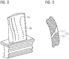
- Fig. 2 is a workpiece with cooling holes - a blade.
- Fig. 3 is a sectional view of a cooling hole in the workpiece in Fig. 2 . It can be seen from Figs. 2 and 3 that multiple cooling holes 10 made using laser pulses are formed in the blade.
- One type of cooling hole may be a gas film hole, mainly comprising a shaped hole part 11.
- the shaped hole part 11 has a special shape, for example trapezoidal or rectangular, which is used to form a gas film of cooling air on a wall surface of the shaped hole part 11, to cool the blade effectively.
- the cooling hole 10 may also comprise a round hole part 12, for guiding cooling air, and causing it to enter the shaped hole part 11.
- Fig. 4 is a flow chart of a method for making a cooling hole in a workpiece using laser light in an embodiment of the present invention.
- the method for making a cooling hole in a workpiece using laser light comprises the following steps: S10, emitting a first laser pulse of high energy to a rough processing part 11A at the position on the workpiece where the shaped hole part 11 is to be made, according to geometric parameters of the shaped hole part 11, to remove material of the workpiece at the rough processing part 11A, and complete rough processing of the shaped hole part 11; and S20, emitting a second laser pulse of low energy to a processing remainder part 11B other than the rough processing part 11A of the shaped hole part 11, according to geometric parameters of the shaped hole part 11, to remove remaining material of the workpiece at the processing remainder part 11B, and complete fine processing of the shaped hole part 11.
- the way in which the method described above is implemented is explained below, taking the processing of cooling holes 10 in a blade 20 as an example.
- the method may use a model of a blade that has been pre-designed using existing computer aided manufacturing software, for example a 3D model of a blade manufactured using CAD software.
- the spatial positions, including three-dimensional spatial coordinates and angles, of cooling holes 10 in the blade may be obtained from the 3D model.
- the method may obtain geometric parameters of a shaped hole part 11 of a cooling hole 10, including the position, shape and size of the shaped hole part, from the 3D model of the blade.
- the rough processing part 11A may be defined, principally taking into account the processing precision requirements of the shaped hole part 11, i.e. the fine processing precision in step S20.
- Figs. 5 and 6 show a process of making a cooling hole 10.
- the shaped hole part 11 of the cooling hole is substantially trapezoidal, and based on experience and process requirements, a cylindrical region which is 3-5 mm distant from the edges of the trapezoidal shape may be defined as the rough processing part 11A.
- a fixed laser 30 may be controlled by the controller 40 to emit multiple first laser pulses to the rough processing part 11A of the shaped hole part, until all or most of the material of the blade 20 at the rough processing part 11A is removed, thereby completing rough processing of the shaped hole part 11. In this way, most of the blade material at the shaped hole part position can be removed.
- the first laser pulse may be a high peak power laser (HPPL), preferably a millisecond laser; by using an HPPL, the blade material at the rough processing part 11A can be removed rapidly.
- HPPL high peak power laser
- a second laser pulse may be emitted to the processing remainder part 11B other than the rough processing part 11A of the shaped hole part 11 on the workpiece according to the geometric parameters shape, position and size of the shaped hole part 11, to remove remaining material of the blade at the processing remainder part 11B, and complete fine processing of the shaped hole part 11.
- a laser 30 (which may be different from the laser used in the process of rough processing of the shaped hole part 11 described above) generates the second laser pulse with a pulse energy greater than that of the first laser pulse; preferably, the second laser pulse is of a level smaller than the nanosecond level (here, including the nanosecond level).
- the laser avoids the rough processing part 11A, i.e. moves back and forth according to a given path at the processing remainder part 11B, removing the material of the blade at the processing remainder part 11B layer by layer, to produce a contour consistent with the shaped hole part 11 of the cooling hole in the 3D model of the blade.
- a fine processing path defined by existing software such as UG (Unigraphic) may be used, or a fine processing path may be determined by a person based on experience. For example, when the shaped hole part 11 shown in Fig. 6 is made, a trapezoidal or oval path may be followed.
- the method in the embodiment described above uses laser pulses of high energy to perform rough processing, removing most of the workpiece material that needs to be removed to make the cooling hole, and thereby reducing the amount of material that needs to be removed when laser pulses of low energy are used to perform fine processing.
- the total processing time of the cooling hole is reduced.
- the method avoids the rough processing part 11A, only emitting laser pulses to the processing remainder part 11B, thus reducing the possibility of laser pulses striking an inside wall of the cooling hole 10, and thereby improving the processing quality of the cooling hole.
- the cooling hole 10 may also comprise a round hole part 12 in communication with the shaped hole part 11.
- the method for making such a cooling hole 10 comprises, in addition to steps S10 and S20 mentioned above: S30, emitting a first laser pulse of high energy to a position on the blade where the round hole part 12 is to be made, according to geometric parameters of the round hole part 12, to remove material of the blade 20 at the position where the round hole part 12 is to be made, and make the round hole part 12.
- geometric parameters of the round hole part 12 of the cooling hole 10 including the position, shape and size of the round hole part, may be obtained from a 3D model of the blade.
- Laser pulses are emitted according to the geometric parameters of the round hole part 12.
- the first laser pulse is also, correspondingly, preferably millisecond laser light.
- step S30 of making the round hole part 12 a millisecond laser may be used to perform step S30 of making the round hole part 12, then step S10 of rough processing and step S20 of fine processing of the shaped hole part 11 may be performed.
- This order may be reversed; first of all, rough processing step S10 for making the shaped hole part 11 is performed, then step S30 of making the round hole part is performed, and finally, step S20 of fine processing of the shaped hole part is performed.
- step S30 of making the round hole part to be performed once step S10 of rough processing and step S20 of fine processing of the shaped hole part 11 have been performed.
- Figs. 7A - 7D are schematic diagrams of another method of making a cooling hole using laser pulses.
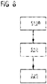
- Fig. 8 is a flow chart of the method.
- the method comprises a step S100: selecting multiple processing regions at the rough processing part 11A according to geometric parameters of the shaped hole part 11, for example four processing regions 11A1, 11A2, 11A3 and 11A4, respectively fixing the laser 30, and emitting first laser pulses of high energy to the selected processing regions 11A1, 11A2, 11A3 and 11A4, to remove material of the workpiece at the rough processing part 11A, thereby completing rough processing of the shaped hole part (11).
- the positions and number of the processing regions on the rough processing part 11A is determined by the geometric parameters of the rough processing part 11A; the positions and number of the processing regions may be determined according to experience. As Figs. 7A - 7D show, multiple processing regions may be selected uniformly in different parts of the rough processing part 11A: top left, top right, bottom left and bottom right. The selection of the number and positions of processing regions must ensure that when laser pulses are emitted to these processing regions, all or most of the blade material within the rough processing part 11A can be removed. These processing regions may partially overlap.
- a second laser pulse of low energy may be emitted to the processing remainder part 11B other than the rough processing part 11A of the shaped hole part 11 on the workpiece according to the geometric parameters shape, position and size of the shaped hole part 11, to remove remaining material of the blade at the processing remainder part 11B, and complete fine processing of the shaped hole part 11.
- S30 is performed in the abovementioned method: emitting a first laser pulse of high energy to a position on the blade where the round hole part 12 is to be made, according to geometric parameters of the round hole part 12, to remove material of the blade 20 at the position where the round hole part 12 is to be made, and make the round hole part 12.
- step S30 of making the round hole part 12 a millisecond laser may be used to perform step S30 of making the round hole part 12, then step S100 of rough processing and step S20 of fine processing of the shaped hole part 11 may be performed.
- Another embodiment of the present invention also discloses a device for making a cooling hole in a workpiece using a laser, the device comprising: a shaped hole part rough processing unit 41, for emitting a first laser pulse of high energy to a rough processing part 11A at a position on the workpiece where a shaped hole part 11 is to be made, according to geometric parameters of the shaped hole part 11, to remove material of the workpiece at the rough processing part 11A, and complete rough processing of the shaped hole part 11; and a shaped hole part fine processing unit 42, for emitting a second laser pulse of low energy to a processing remainder part 11B of the shaped hole part 11, according to geometric parameters of the shaped hole part 11, to remove remaining material of the workpiece at the processing remainder part 11B, and complete fine processing of the shaped hole part 11.
- the shaped hole part rough processing unit 41 is specifically for: selecting multiple processing regions 11A1, 11A2, 11A3 and 11A4 at the rough processing part 11A according to geometric parameters of the shaped hole part 11, and emitting first laser pulses to the selected processing regions 11A1, 11A2, 11A3 and 11A4, to remove material of the workpiece at the rough processing part 11A, thereby completing rough processing of the shaped hole part 11.
- the device also comprises: a round hole part processing unit 43, for emitting a first laser pulse of high energy to a position on the workpiece where the round hole part 12 is to be made, according to geometric parameters of the round hole part 12, to remove material of the workpiece at the position where the round hole part 12 is to be made, and make the round hole part 12.
- the first laser pulse may be millisecond laser light; the second laser pulse may be laser light of a level smaller than the nanosecond level.
- the shaped hole part rough processing unit 41, shaped hole part fine processing unit 42 and round hole part processing unit 43 may be realized not only using software, but also using a hardware circuit such as a field programmable gate array (FPGA), an ASIC chip or a complex programmable logic device (CPLD).
- FPGA field programmable gate array
- ASIC application specific integrated circuit
- CPLD complex programmable logic device
- Another embodiment of the present invention also discloses a system for making a cooling hole in a workpiece, the system comprising: a laser 30, for generating a laser pulse onto the workpiece; and a controller 40, in which is stored a program for realizing the abovementioned method for making a cooling hole in a workpiece.
- Another embodiment of the present invention also discloses a machine readable storage medium, in which are stored commands for making a machine perform the abovementioned method for making a cooling hole in a workpiece.
Landscapes
- Physics & Mathematics (AREA)
- Optics & Photonics (AREA)
- Engineering & Computer Science (AREA)
- Plasma & Fusion (AREA)
- Mechanical Engineering (AREA)
- Laser Beam Processing (AREA)
Abstract
Description
- The present invention relates to a laser processing method and device, in particular to a method and device for making a cooling hole in a workpiece using laser pulses.
- Laser processing is highly efficient, is not affected by the attributes of the material being processed, and has reliable processing quality, so is used in many technical fields. For example, there are already technologies which use laser pulses to make holes in certain components of compressors, fuel injection nozzles, and the blades (including moving blades and static blades) of aviation engines and industrial gas turbines. For example, taking blades as an example, these are generally hollow components made from a high-temperature alloy material; they have a high operating temperature, and bear large loads. It is generally necessary to form multiple cooling holes, made using laser pulses, in the blades, in order to continuously cool the blades.
- One embodiment of the present invention discloses a method for making a cooling hole in a workpiece using laser light, the cooling hole comprising a shaped hole part, and the method comprising the following steps: S10, emitting a first laser pulse to a rough processing part at the position on the workpiece where the shaped hole part is to be made, according to geometric parameters of the shaped hole part, to remove material of the workpiece at the rough processing part, and complete rough processing of the shaped hole part; and S20, emitting a second laser pulse to a processing remainder part other than the rough processing part of the shaped hole part, according to geometric parameters of the shaped hole part, to remove remaining material of the workpiece at the processing remainder part, and complete fine processing of the shaped hole part; wherein the energy of the first laser pulse is greater than the energy of the second laser pulse. It must be explained here that the processing remainder part of the shaped hole part is a region other than the rough processing part of the shaped hole part. Here, "geometric parameters" of the shaped hole part include the geometric shape and size etc. of the shaped hole part.
- Another embodiment of the present invention further discloses a device for making a cooling hole in a workpiece using laser light, the cooling hole comprising a shaped hole part, the device comprising: a shaped hole part rough processing unit, for emitting a first laser pulse to a rough processing part of the shaped hole part, according to geometric parameters of the shaped hole part, to remove material of the workpiece at the rough processing part, and complete rough processing of the shaped hole part; and a shaped hole part fine processing unit, for emitting a second laser pulse to a processing remainder part of the shaped hole part, according to geometric parameters of the shaped hole part, to remove remaining material of the workpiece at the processing remainder part, and complete fine processing of the shaped hole part; wherein the energy of the first laser pulse is greater than the energy of the second laser pulse.
- Another embodiment of the present invention further discloses a system for making a cooling hole in a workpiece, the system comprising: a laser, for generating a laser pulse onto the workpiece; and a controller, in which is stored a program for realizing the abovementioned method for making a cooling hole in a workpiece.
- Another embodiment of the present invention further discloses a machine readable storage medium, characterized by storing commands for making the machine perform the abovementioned method.
-
-
Fig. 1 is a system for making a cooling hole in a workpiece; -
Fig. 2 is a workpiece with cooling holes - a blade; -
Fig. 3 is a sectional view of a cooling hole in the workpiece inFig. 2 ; -
Fig. 4 is a flow chart of a method for making a cooling hole in a workpiece using laser light in an embodiment of the present invention; -
Figs. 5 and6 are schematic diagrams of different parts of a cooling hole made using laser pulses; -
Figs. 7A - 7D are schematic diagrams of another method of making a cooling hole using laser pulses; -
Fig. 8 is a flow chart of the method shown inFigs. 7A - 7D . - List of names and numbers of components in the figures:
-
Workpiece 20,laser 30,controller 40,camera 50,cooling hole 10,shaped hole part 11,rough processing part 11A ofshaped hole part 11, processing regions 11A1, 11A2, 11A3 and 11A4 ofrough processing part 11A, processingremainder part 11B of shaped hole part,round hole part 12, shaped hole partrough processing unit 41, shaped hole partfine processing unit 42, round holepart processing unit 43 - To clarify the object, technical solution and advantages of the embodiments of the present invention, embodiments of the present invention are explained in further detail below by means of examples.
-
Fig. 1 is a system for making a cooling hole in a workpiece. Acontroller 40 controls alaser 30 to generate a laser pulse which is emitted through a nozzle onto aworkpiece 20 in which a cooling hole is to be made. Material in a processing region of theworkpiece 20 is heated, melted and evaporated by the laser beam that is shot onto said material. A program of the method for making a cooling hole according to the present invention may be stored in thecontroller 40, for controlling thelaser 30 to generate a laser pulse. Furthermore, the system described above may also comprise animage sensor 50, which collects visible light emitted by the processing region of theworkpiece 20, and forms an image of the processing region and transmits said image to thecontroller 40; the controller can determine whether processing is complete based on the image of the processing region. -
Fig. 2 is a workpiece with cooling holes - a blade.Fig. 3 is a sectional view of a cooling hole in the workpiece inFig. 2 . It can be seen fromFigs. 2 and 3 thatmultiple cooling holes 10 made using laser pulses are formed in the blade. One type of cooling hole may be a gas film hole, mainly comprising ashaped hole part 11. Theshaped hole part 11 has a special shape, for example trapezoidal or rectangular, which is used to form a gas film of cooling air on a wall surface of theshaped hole part 11, to cool the blade effectively. Thecooling hole 10 may also comprise around hole part 12, for guiding cooling air, and causing it to enter theshaped hole part 11. -
Fig. 4 is a flow chart of a method for making a cooling hole in a workpiece using laser light in an embodiment of the present invention. The method for making a cooling hole in a workpiece using laser light comprises the following steps: S10, emitting a first laser pulse of high energy to arough processing part 11A at the position on the workpiece where theshaped hole part 11 is to be made, according to geometric parameters of theshaped hole part 11, to remove material of the workpiece at therough processing part 11A, and complete rough processing of theshaped hole part 11; and S20, emitting a second laser pulse of low energy to aprocessing remainder part 11B other than therough processing part 11A of theshaped hole part 11, according to geometric parameters of theshaped hole part 11, to remove remaining material of the workpiece at theprocessing remainder part 11B, and complete fine processing of theshaped hole part 11. - The way in which the method described above is implemented is explained below, taking the processing of
cooling holes 10 in ablade 20 as an example. The method may use a model of a blade that has been pre-designed using existing computer aided manufacturing software, for example a 3D model of a blade manufactured using CAD software. The spatial positions, including three-dimensional spatial coordinates and angles, ofcooling holes 10 in the blade may be obtained from the 3D model. The method may obtain geometric parameters of ashaped hole part 11 of acooling hole 10, including the position, shape and size of the shaped hole part, from the 3D model of the blade. Based on the geometric parameters of theshaped hole part 11, and according to the process requirements for making the cooling hole, therough processing part 11A may be defined, principally taking into account the processing precision requirements of theshaped hole part 11, i.e. the fine processing precision in step S20. - For example,
Figs. 5 and6 show a process of making acooling hole 10. Theshaped hole part 11 of the cooling hole is substantially trapezoidal, and based on experience and process requirements, a cylindrical region which is 3-5 mm distant from the edges of the trapezoidal shape may be defined as therough processing part 11A. With regard to therough processing part 11A based on definition, a fixedlaser 30 may be controlled by thecontroller 40 to emit multiple first laser pulses to therough processing part 11A of the shaped hole part, until all or most of the material of theblade 20 at therough processing part 11A is removed, thereby completing rough processing of theshaped hole part 11. In this way, most of the blade material at the shaped hole part position can be removed. The first laser pulse may be a high peak power laser (HPPL), preferably a millisecond laser; by using an HPPL, the blade material at therough processing part 11A can be removed rapidly. - As
Fig. 6 shows, building upon the rough processing of theshaped hole part 11, a second laser pulse may be emitted to theprocessing remainder part 11B other than therough processing part 11A of theshaped hole part 11 on the workpiece according to the geometric parameters shape, position and size of theshaped hole part 11, to remove remaining material of the blade at theprocessing remainder part 11B, and complete fine processing of theshaped hole part 11. In the fine processing step, a laser 30 (which may be different from the laser used in the process of rough processing of theshaped hole part 11 described above) generates the second laser pulse with a pulse energy greater than that of the first laser pulse; preferably, the second laser pulse is of a level smaller than the nanosecond level (here, including the nanosecond level). The laser avoids therough processing part 11A, i.e. moves back and forth according to a given path at theprocessing remainder part 11B, removing the material of the blade at theprocessing remainder part 11B layer by layer, to produce a contour consistent with theshaped hole part 11 of the cooling hole in the 3D model of the blade. A fine processing path defined by existing software such as UG (Unigraphic) may be used, or a fine processing path may be determined by a person based on experience. For example, when theshaped hole part 11 shown inFig. 6 is made, a trapezoidal or oval path may be followed. - The method in the embodiment described above uses laser pulses of high energy to perform rough processing, removing most of the workpiece material that needs to be removed to make the cooling hole, and thereby reducing the amount of material that needs to be removed when laser pulses of low energy are used to perform fine processing. Thus, the total processing time of the cooling hole is reduced. Moreover, during fine processing, the method avoids the
rough processing part 11A, only emitting laser pulses to theprocessing remainder part 11B, thus reducing the possibility of laser pulses striking an inside wall of thecooling hole 10, and thereby improving the processing quality of the cooling hole. - As shown in
Figs. 5 and6 , in another embodiment of the present invention, thecooling hole 10 may also comprise around hole part 12 in communication with theshaped hole part 11. Correspondingly, the method for making such acooling hole 10 comprises, in addition to steps S10 and S20 mentioned above: S30, emitting a first laser pulse of high energy to a position on the blade where theround hole part 12 is to be made, according to geometric parameters of theround hole part 12, to remove material of theblade 20 at the position where theround hole part 12 is to be made, and make theround hole part 12. Similarly to the rough processing of theshaped hole part 11, geometric parameters of theround hole part 12 of thecooling hole 10, including the position, shape and size of the round hole part, may be obtained from a 3D model of the blade. Laser pulses are emitted according to the geometric parameters of theround hole part 12. Here, the first laser pulse is also, correspondingly, preferably millisecond laser light. - It must be explained here that the numbering of the steps and the order of the explanations herein do not represent the order in which these steps are performed. For example, first of all a millisecond laser may be used to perform step S30 of making the
round hole part 12, then step S10 of rough processing and step S20 of fine processing of the shapedhole part 11 may be performed. This order may be reversed; first of all, rough processing step S10 for making the shapedhole part 11 is performed, then step S30 of making the round hole part is performed, and finally, step S20 of fine processing of the shaped hole part is performed. Moreover, it is also possible for step S30 of making the round hole part to be performed once step S10 of rough processing and step S20 of fine processing of the shapedhole part 11 have been performed. - In an alternative example of the abovementioned method, rough processing of the shaped hole part may be implemented in the following way.
Figs. 7A - 7D are schematic diagrams of another method of making a cooling hole using laser pulses.Fig. 8 is a flow chart of the method. The method comprises a step S100: selecting multiple processing regions at therough processing part 11A according to geometric parameters of the shapedhole part 11, for example four processing regions 11A1, 11A2, 11A3 and 11A4, respectively fixing thelaser 30, and emitting first laser pulses of high energy to the selected processing regions 11A1, 11A2, 11A3 and 11A4, to remove material of the workpiece at therough processing part 11A, thereby completing rough processing of the shaped hole part (11). The positions and number of the processing regions on therough processing part 11A is determined by the geometric parameters of therough processing part 11A; the positions and number of the processing regions may be determined according to experience. AsFigs. 7A - 7D show, multiple processing regions may be selected uniformly in different parts of therough processing part 11A: top left, top right, bottom left and bottom right. The selection of the number and positions of processing regions must ensure that when laser pulses are emitted to these processing regions, all or most of the blade material within therough processing part 11A can be removed. These processing regions may partially overlap. - S30, emitting a first laser pulse of high energy to a position on the blade where the
round hole part 12 is to be made, according to geometric parameters of theround hole part 12, to remove material of theblade 20 at the position where theround hole part 12 is to be made, and make theround hole part 12. - Building upon the rough processing of the shaped
hole part 11, a second laser pulse of low energy may be emitted to theprocessing remainder part 11B other than therough processing part 11A of the shapedhole part 11 on the workpiece according to the geometric parameters shape, position and size of the shapedhole part 11, to remove remaining material of the blade at theprocessing remainder part 11B, and complete fine processing of the shapedhole part 11. After fine processing of the shaped hole part, S30 is performed in the abovementioned method: emitting a first laser pulse of high energy to a position on the blade where theround hole part 12 is to be made, according to geometric parameters of theround hole part 12, to remove material of theblade 20 at the position where theround hole part 12 is to be made, and make theround hole part 12. The fine processing step and round hole processing step described above are the same as those explained previously, so are not explained in detail again here. Similarly, the numbering of the steps and the order of the explanations here do not represent the order in which these steps are performed. For example, first of all a millisecond laser may be used to perform step S30 of making theround hole part 12, then step S100 of rough processing and step S20 of fine processing of the shapedhole part 11 may be performed. - Another embodiment of the present invention also discloses a device for making a cooling hole in a workpiece using a laser, the device comprising: a shaped hole part
rough processing unit 41, for emitting a first laser pulse of high energy to arough processing part 11A at a position on the workpiece where a shapedhole part 11 is to be made, according to geometric parameters of the shapedhole part 11, to remove material of the workpiece at therough processing part 11A, and complete rough processing of the shapedhole part 11; and a shaped hole partfine processing unit 42, for emitting a second laser pulse of low energy to aprocessing remainder part 11B of the shapedhole part 11, according to geometric parameters of the shapedhole part 11, to remove remaining material of the workpiece at theprocessing remainder part 11B, and complete fine processing of the shapedhole part 11. - In one embodiment of the present invention, the shaped hole part
rough processing unit 41 is specifically for: selecting multiple processing regions 11A1, 11A2, 11A3 and 11A4 at therough processing part 11A according to geometric parameters of the shapedhole part 11, and emitting first laser pulses to the selected processing regions 11A1, 11A2, 11A3 and 11A4, to remove material of the workpiece at therough processing part 11A, thereby completing rough processing of the shapedhole part 11. - In one embodiment of the present invention, the device also comprises: a round hole
part processing unit 43, for emitting a first laser pulse of high energy to a position on the workpiece where theround hole part 12 is to be made, according to geometric parameters of theround hole part 12, to remove material of the workpiece at the position where theround hole part 12 is to be made, and make theround hole part 12. The first laser pulse may be millisecond laser light; the second laser pulse may be laser light of a level smaller than the nanosecond level. - The shaped hole part
rough processing unit 41, shaped hole partfine processing unit 42 and round holepart processing unit 43 may be realized not only using software, but also using a hardware circuit such as a field programmable gate array (FPGA), an ASIC chip or a complex programmable logic device (CPLD). - Another embodiment of the present invention also discloses a system for making a cooling hole in a workpiece, the system comprising: a
laser 30, for generating a laser pulse onto the workpiece; and acontroller 40, in which is stored a program for realizing the abovementioned method for making a cooling hole in a workpiece. - Another embodiment of the present invention also discloses a machine readable storage medium, in which are stored commands for making a machine perform the abovementioned method for making a cooling hole in a workpiece.
- The embodiments above are merely preferred embodiments of the present invention, which are not intended to define the scope of protection of the present invention. Suitable improvements may be made to the preferred embodiments according to the present invention during specific implementation, to suit the specific requirements of the particular circumstances. Thus, it can be understood that the particular embodiments of the present invention mentioned herein merely serve a demonstrative function, and are not intended to limit the scope of protection of the present invention.
Claims (10)
- A method for making a cooling hole in a workpiece using laser light, the cooling hole (10) comprising a shaped hole part (11), and the method comprising the following steps:S10, emitting a first laser pulse to a rough processing part (11A) at the position on the workpiece where the shaped hole part (11) is to be made, according to geometric parameters of the shaped hole part (11), to remove material of the workpiece at the rough processing part (11A), and complete rough processing of the shaped hole part (11); andS20, emitting a second laser pulse to a processing remainder part (11B) other than the rough processing part (11A) of the shaped hole part (11), according to geometric parameters of the shaped hole part (11), to remove remaining material of the workpiece at the processing remainder part (11B), and complete fine processing of the shaped hole part (11);wherein the energy of the first laser pulse is greater than the energy of the second laser pulse.
- The method as claimed in claim 1, wherein step S10 further is:5100, selecting multiple processing regions (11A1, 11A2, 11A3, 11A4) at the rough processing part (11A) according to geometric parameters of the shaped hole part (11), and emitting first laser pulses to the selected processing regions (11A1, 11A2, 11A3, 11A4), to remove material of the workpiece at the rough processing part (11A), thereby completing rough processing of the shaped hole part (12).
- The method as claimed in claim 1, wherein the cooling hole (10) also comprises a round hole part (12) in communication with the shaped hole part (11), and the method also comprises:S30, emitting a first laser pulse to a position on the workpiece where the round hole part (12) is to be made, according to geometric parameters of the round hole part (12),to remove material of the workpiece at the position where the round hole part (12) is to be made, and make the round hole part (12).
- The method as claimed in claim 1, wherein the first laser pulse is of the millisecond level, and the second laser pulse is of a level smaller than the nanosecond level.
- A device for making a cooling hole in a workpiece using laser light, the cooling hole (10) comprising a shaped hole part (11), the device comprising:a shaped hole part rough processing unit (41), for emitting a first laser pulse to a rough processing part (11A) at the position of the shaped hole part (11), according to geometric parameters of the shaped hole part (11), to remove material of the workpiece at the rough processing part (11A), and complete rough processing of the shaped hole part (11); anda shaped hole part fine processing unit (42), for emitting a second laser pulse to a processing remainder part (11B) other than the rough processing part (11A) of the shaped hole part (11), according to geometric parameters of the shaped hole part (11), to remove remaining material of the workpiece at the processing remainder part (11B), and complete fine processing of the shaped hole part (11);wherein the energy of the first laser pulse is greater than the energy of the second laser pulse.
- The device as claimed in claim 5, wherein the shaped hole part rough processing unit (41) is specifically for: selecting multiple processing regions (11A1, 11A2, 11A3, 11A4) at the rough processing part (11A) according to geometric parameters of the shaped hole part (11), and emitting first laser pulses to the selected processing regions (11A1, 11A2, 11A3, 11A4), to remove material of the workpiece at the rough processing part (11A), thereby completing rough processing of the shaped hole part (12).
- The device as claimed in claim 5, wherein the cooling hole (10) also comprises a round hole part (11), and the device also comprises: a round hole part processing unit (43), for emitting a first laser pulse to a position on the workpiece where the round hole part (12) is to be made, according to geometric parameters of the round hole part (12), to remove material of the workpiece at the position where the round hole part (12) is to be made, and make the round hole part (12).
- The device as claimed in claim 5, wherein the first laser pulse is of the millisecond level, and the second laser pulse is of a level smaller than the nanosecond level.
- A system for making a cooling hole in a workpiece, comprising:a laser (30), for generating a laser pulse onto the workpiece; anda controller (40), in which is stored a program for realizing the method as claimed in any one of claims 1 - 4 for making a cooling hole in a workpiece.
- A machine readable storage medium, characterized by storing commands for making a machine perform the method as claimed in any one of claims 1 - 4.
Applications Claiming Priority (1)
| Application Number | Priority Date | Filing Date | Title |
|---|---|---|---|
| PCT/CN2014/090738 WO2016074135A1 (en) | 2014-11-10 | 2014-11-10 | Method and device for processing cooling hole on workpiece with laser |
Publications (2)
| Publication Number | Publication Date |
|---|---|
| EP3219431A1 true EP3219431A1 (en) | 2017-09-20 |
| EP3219431A4 EP3219431A4 (en) | 2018-07-11 |
Family
ID=55953541
Family Applications (1)
| Application Number | Title | Priority Date | Filing Date |
|---|---|---|---|
| EP14905737.4A Withdrawn EP3219431A4 (en) | 2014-11-10 | 2014-11-10 | Method and device for processing cooling hole on workpiece with laser |
Country Status (4)
| Country | Link |
|---|---|
| US (1) | US11117222B2 (en) |
| EP (1) | EP3219431A4 (en) |
| CN (1) | CN106536123A (en) |
| WO (1) | WO2016074135A1 (en) |
Families Citing this family (7)
| Publication number | Priority date | Publication date | Assignee | Title |
|---|---|---|---|---|
| CN109732202B (en) * | 2019-02-26 | 2021-01-15 | 江苏大学 | Ultra-fast laser rotary cutting processing method for deep micro-holes |
| CN111673299A (en) * | 2020-04-30 | 2020-09-18 | 西门子燃气轮机部件(江苏)有限公司 | Method and apparatus for forming cooling holes in turbine blades, computer readable medium |
| CN120244306A (en) * | 2021-01-19 | 2025-07-04 | 深圳市大族数控科技股份有限公司 | Micro blind hole processing method and ultrafast laser processing equipment |
| CN113146074A (en) * | 2021-02-25 | 2021-07-23 | 贵阳航发精密铸造有限公司 | Machining method of air film hole in turbine blade |
| US20230193772A1 (en) * | 2021-12-21 | 2023-06-22 | Raytheon Technologies Corporation | Fabrication of cooling holes using laser machining and ultrasonic machining |
| CN116638208B (en) * | 2023-04-24 | 2026-03-10 | 西北工业大学 | Method for preparing turbine blade dustpan type air film hole by femtosecond laser |
| CN118951591A (en) * | 2024-08-21 | 2024-11-15 | 国营川西机器厂 | Turbine guide blade repair tool and method |
Family Cites Families (22)
| Publication number | Priority date | Publication date | Assignee | Title |
|---|---|---|---|---|
| US6744010B1 (en) | 1991-08-22 | 2004-06-01 | United Technologies Corporation | Laser drilled holes for film cooling |
| DE59802893D1 (en) | 1998-03-23 | 2002-03-14 | Alstom | Non-circular cooling hole and method of manufacturing the same |
| US6420677B1 (en) * | 2000-12-20 | 2002-07-16 | Chromalloy Gas Turbine Corporation | Laser machining cooling holes in gas turbine components |
| US6864459B2 (en) | 2001-02-08 | 2005-03-08 | The Regents Of The University Of California | High precision, rapid laser hole drilling |
| US6809291B1 (en) * | 2002-08-30 | 2004-10-26 | Southeastern Universities Research Assn., Inc. | Process for laser machining and surface treatment |
| US7041933B2 (en) * | 2003-04-14 | 2006-05-09 | Meyer Tool, Inc. | Complex hole shaping |
| US7816625B2 (en) * | 2003-10-06 | 2010-10-19 | Siemens Aktiengesellschaft | Method for the production of a hole and device |
| DE102004034721A1 (en) | 2004-07-17 | 2006-02-16 | Alstom Technology Ltd | Laser process for forming a hole especially an air cooling hole in a layered workpiece especially a turbine component first removes cover layer then bores into base |
| EP1681128A1 (en) * | 2005-01-14 | 2006-07-19 | Siemens Aktiengesellschaft | Method and device for producing a hole |
| EP1712739A1 (en) | 2005-04-12 | 2006-10-18 | Siemens Aktiengesellschaft | Component with film cooling hole |
| JP4931507B2 (en) | 2005-07-26 | 2012-05-16 | スネクマ | Cooling flow path formed in the wall |
| EP1806203A1 (en) * | 2006-01-10 | 2007-07-11 | Siemens Aktiengesellschaft | Method of producing a hole |
| EP2105240B1 (en) * | 2008-03-28 | 2011-10-05 | Siemens Aktiengesellschaft | Method for creating a drill hole |
| CN101332559B (en) | 2008-07-18 | 2011-06-01 | 西安交通大学 | Laser compound processing and modifying method of no-recasting-layer micro deep-hole |
| US8964801B2 (en) * | 2009-06-11 | 2015-02-24 | Esi-Pyrophotonics Lasers, Inc. | Method and system for stable and tunable high power pulsed laser system |
| EP2292372B1 (en) | 2009-08-17 | 2012-10-03 | Siemens Aktiengesellschaft | Method for making a hole using different laser positions |
| US20110132883A1 (en) * | 2009-12-07 | 2011-06-09 | Panasonic Corporation | Methods for precise laser micromachining |
| US9696035B2 (en) | 2010-10-29 | 2017-07-04 | General Electric Company | Method of forming a cooling hole by laser drilling |
| US20120102959A1 (en) * | 2010-10-29 | 2012-05-03 | John Howard Starkweather | Substrate with shaped cooling holes and methods of manufacture |
| US8624151B2 (en) | 2011-07-19 | 2014-01-07 | Pratt & Whitney Canada Corp. | Laser drilling methods of shallow-angled holes |
| CA2849183C (en) | 2013-05-01 | 2016-12-06 | General Electric Company | Substrate with shaped cooling holes and methods of manufacture |
| CN103990910B (en) | 2014-05-20 | 2015-08-05 | 西安交通大学 | A kind of preparation method with thermal barrier coating turbine blade air film Cooling Holes |
-
2014
- 2014-11-10 EP EP14905737.4A patent/EP3219431A4/en not_active Withdrawn
- 2014-11-10 CN CN201480080696.1A patent/CN106536123A/en active Pending
- 2014-11-10 US US15/500,603 patent/US11117222B2/en not_active Expired - Fee Related
- 2014-11-10 WO PCT/CN2014/090738 patent/WO2016074135A1/en not_active Ceased
Also Published As
| Publication number | Publication date |
|---|---|
| US11117222B2 (en) | 2021-09-14 |
| US20170232559A1 (en) | 2017-08-17 |
| WO2016074135A1 (en) | 2016-05-19 |
| EP3219431A4 (en) | 2018-07-11 |
| CN106536123A (en) | 2017-03-22 |
Similar Documents
| Publication | Publication Date | Title |
|---|---|---|
| US11117222B2 (en) | Method and device for processing cooling hole on workpiece with laser | |
| US9573273B2 (en) | Robot simulation device for generating motion path of robot | |
| JP7221002B2 (en) | Method for preparing hybrid article | |
| CN108320268B (en) | A femtosecond laser complex component large-area manufacturing method | |
| CN105911956A (en) | Machine tool | |
| TWI583477B (en) | Laser machining system and method using beam locator controlled by laser radiation | |
| EP3098002B1 (en) | Compound 3d printing device for electron beam melting and cutting | |
| US20160052057A1 (en) | Gas turbine component manufacturing | |
| CN108326301B (en) | Printing path generation method for metal additive manufacturing | |
| US11733678B2 (en) | Method for determining building instructions for an additive manufacturing method, method for generating a database with correction measures for controlling the process of an additive manufacturing method | |
| US20160082545A1 (en) | Nc program generating device and nc program generating method | |
| CN108422670B (en) | A Path Planning Method for 3D Point Cloud Surface Divided by Discontinuous Grid | |
| EP1429368A3 (en) | Fabrication of three dimensional structures | |
| RU2013142839A (en) | METHOD, SYSTEM AND COMPUTER PROGRAM FOR MACHINE CUTTING OF SEVERAL PARTS FROM BILLING OF MATERIAL USING REGULATORY RULES AND VARIABLES FOR CUTTING | |
| CN109466057A (en) | Method, FDM printing device, storage medium, and processor for eliminating print stringing | |
| JP2013508179A (en) | Tool compensation method and device | |
| CN108971901A (en) | A kind of impact type waterturbine wheel repairing reproduction method | |
| CN101543939B (en) | Method for creating bore | |
| US9517506B2 (en) | Laser assisted casting of cooling hole and related system | |
| WO2015170639A1 (en) | Laser processing machine, composite processing system, composite processing machine, and processing origin correction method | |
| JP2016147269A (en) | On-the-fly path generation apparatus and method | |
| WO2022214161A1 (en) | Method of producing three-dimensional object, control system and additive manufacturing device | |
| JP2017113849A (en) | Numerically controlled machine tool | |
| Xiong et al. | Time-optimal scan path planning based on analysis of sliced geometry | |
| CN113070589B (en) | Laser cutting method, apparatus and computer readable storage medium |
Legal Events
| Date | Code | Title | Description |
|---|---|---|---|
| STAA | Information on the status of an ep patent application or granted ep patent |
Free format text: STATUS: THE INTERNATIONAL PUBLICATION HAS BEEN MADE |
|
| PUAI | Public reference made under article 153(3) epc to a published international application that has entered the european phase |
Free format text: ORIGINAL CODE: 0009012 |
|
| STAA | Information on the status of an ep patent application or granted ep patent |
Free format text: STATUS: REQUEST FOR EXAMINATION WAS MADE |
|
| 17P | Request for examination filed |
Effective date: 20170317 |
|
| AK | Designated contracting states |
Kind code of ref document: A1 Designated state(s): AL AT BE BG CH CY CZ DE DK EE ES FI FR GB GR HR HU IE IS IT LI LT LU LV MC MK MT NL NO PL PT RO RS SE SI SK SM TR |
|
| AX | Request for extension of the european patent |
Extension state: BA ME |
|
| DAX | Request for extension of the european patent (deleted) | ||
| A4 | Supplementary search report drawn up and despatched |
Effective date: 20180613 |
|
| RIC1 | Information provided on ipc code assigned before grant |
Ipc: B23K 101/00 20060101ALI20180607BHEP Ipc: B23K 26/0622 20140101ALI20180607BHEP Ipc: B23K 26/384 20140101AFI20180607BHEP Ipc: B23K 26/382 20140101ALI20180607BHEP |
|
| STAA | Information on the status of an ep patent application or granted ep patent |
Free format text: STATUS: EXAMINATION IS IN PROGRESS |
|
| 17Q | First examination report despatched |
Effective date: 20200207 |
|
| RAP1 | Party data changed (applicant data changed or rights of an application transferred) |
Owner name: SIEMENS ENERGY GLOBAL GMBH & CO. KG |
|
| GRAP | Despatch of communication of intention to grant a patent |
Free format text: ORIGINAL CODE: EPIDOSNIGR1 |
|
| STAA | Information on the status of an ep patent application or granted ep patent |
Free format text: STATUS: GRANT OF PATENT IS INTENDED |
|
| INTG | Intention to grant announced |
Effective date: 20220324 |
|
| STAA | Information on the status of an ep patent application or granted ep patent |
Free format text: STATUS: THE APPLICATION IS DEEMED TO BE WITHDRAWN |
|
| 18D | Application deemed to be withdrawn |
Effective date: 20220804 |