EP3219036B1 - Übertragungsknoten und darin durchgeführte verfahren - Google Patents
Übertragungsknoten und darin durchgeführte verfahren Download PDFInfo
- Publication number
- EP3219036B1 EP3219036B1 EP14805381.2A EP14805381A EP3219036B1 EP 3219036 B1 EP3219036 B1 EP 3219036B1 EP 14805381 A EP14805381 A EP 14805381A EP 3219036 B1 EP3219036 B1 EP 3219036B1
- Authority
- EP
- European Patent Office
- Prior art keywords
- energy
- burst
- code
- shift
- additional information
- Prior art date
- Legal status (The legal status is an assumption and is not a legal conclusion. Google has not performed a legal analysis and makes no representation as to the accuracy of the status listed.)
- Not-in-force
Links
Images


Classifications
-
- H—ELECTRICITY
- H04—ELECTRIC COMMUNICATION TECHNIQUE
- H04L—TRANSMISSION OF DIGITAL INFORMATION, e.g. TELEGRAPHIC COMMUNICATION
- H04L5/00—Arrangements affording multiple use of the transmission path
- H04L5/003—Arrangements for allocating sub-channels of the transmission path
- H04L5/0044—Arrangements for allocating sub-channels of the transmission path allocation of payload
-
- H—ELECTRICITY
- H04—ELECTRIC COMMUNICATION TECHNIQUE
- H04L—TRANSMISSION OF DIGITAL INFORMATION, e.g. TELEGRAPHIC COMMUNICATION
- H04L1/00—Arrangements for detecting or preventing errors in the information received
- H04L1/02—Arrangements for detecting or preventing errors in the information received by diversity reception
- H04L1/06—Arrangements for detecting or preventing errors in the information received by diversity reception using space diversity
- H04L1/0618—Space-time coding
- H04L1/0637—Properties of the code
- H04L1/0643—Properties of the code block codes
-
- H—ELECTRICITY
- H04—ELECTRIC COMMUNICATION TECHNIQUE
- H04B—TRANSMISSION
- H04B7/00—Radio transmission systems, i.e. using radiation field
- H04B7/02—Diversity systems; Multi-antenna system, i.e. transmission or reception using multiple antennas
- H04B7/04—Diversity systems; Multi-antenna system, i.e. transmission or reception using multiple antennas using two or more spaced independent antennas
- H04B7/06—Diversity systems; Multi-antenna system, i.e. transmission or reception using multiple antennas using two or more spaced independent antennas at the transmitting station
- H04B7/0613—Diversity systems; Multi-antenna system, i.e. transmission or reception using multiple antennas using two or more spaced independent antennas at the transmitting station using simultaneous transmission
- H04B7/0667—Diversity systems; Multi-antenna system, i.e. transmission or reception using multiple antennas using two or more spaced independent antennas at the transmitting station using simultaneous transmission of delayed versions of same signal
- H04B7/0669—Diversity systems; Multi-antenna system, i.e. transmission or reception using multiple antennas using two or more spaced independent antennas at the transmitting station using simultaneous transmission of delayed versions of same signal using different channel coding between antennas
-
- H—ELECTRICITY
- H04—ELECTRIC COMMUNICATION TECHNIQUE
- H04L—TRANSMISSION OF DIGITAL INFORMATION, e.g. TELEGRAPHIC COMMUNICATION
- H04L5/00—Arrangements affording multiple use of the transmission path
- H04L5/0091—Signaling for the administration of the divided path
- H04L5/0092—Indication of how the channel is divided
-
- H—ELECTRICITY
- H04—ELECTRIC COMMUNICATION TECHNIQUE
- H04L—TRANSMISSION OF DIGITAL INFORMATION, e.g. TELEGRAPHIC COMMUNICATION
- H04L1/00—Arrangements for detecting or preventing errors in the information received
- H04L1/02—Arrangements for detecting or preventing errors in the information received by diversity reception
- H04L1/06—Arrangements for detecting or preventing errors in the information received by diversity reception using space diversity
- H04L1/0618—Space-time coding
- H04L1/0637—Properties of the code
- H04L1/0668—Orthogonal systems, e.g. using Alamouti codes
Definitions
- Embodiments herein relate to a transmitting node, a receiving node and methods performed therein.
- embodiments herein relate to transmitting a burst of energy in a wireless communication network.
- wireless devices also known as mobile stations and/or user equipments (UEs) communicate via a Radio Access Network (RAN) to one or more core networks.
- the RAN covers a geographical area which is divided into cell areas, with each cell area being served by a base station, e.g., a radio base station (RBS), which in some networks may also be called, for example, a "NodeB” or "eNodeB” (eNB).
- RBS radio base station
- eNB eNodeB
- a cell is a geographical area where radio coverage is provided by the radio base station at a base station site or an antenna site in case the antenna and the radio base station are not collocated.
- Each cell is identified by an identity within the local radio area, which is broadcast in the cell. Another identity identifying the cell uniquely in the whole wireless communication network is also broadcasted in the cell.
- One base station may have one or more cells. The base stations communicate over the air interface operating on radio frequencies with the wireless devices within range of the base stations.
- a Universal Mobile Telecommunications System is a third generation mobile communication system, which evolved from the second generation (2G) Global System for Mobile Communications (GSM).
- the UMTS terrestrial radio access network is essentially a RAN using wideband code division multiple access (WCDMA) and/or High Speed Packet Access (HSPA) for wireless devices.
- WCDMA wideband code division multiple access
- HSPA High Speed Packet Access
- 3GPP Third Generation Partnership Project
- telecommunications suppliers propose and agree upon standards for third generation networks and UTRAN specifically, and investigate enhanced data rate and radio capacity.
- the RAN as e.g.
- RNC radio network controller
- BSC base station controller
- the Evolved Packet System comprises the Evolved Universal Terrestrial Radio Access Network (E-UTRAN), also known as the Long Term Evolution (LTE) radio access, and the Evolved Packet Core (EPC), also known as System Architecture Evolution (SAE) core network.
- E-UTRAN/LTE is a variant of a 3GPP radio access technology wherein the radio base stations are directly connected to the EPC core network rather than to RNCs.
- the functions of a RNC are distributed between the radio base stations, called eNodeBs in LTE, and the core network.
- the Radio Access Network (RAN) of an EPS has an essentially "flat" architecture comprising radio base stations without reporting to RNCs.
- WO0247278 is related to a system and method for use in a CDMA communication system including a plurality of base stations and a user equipment (UE), each for communicating with each other.
- the base station has a transmitter which includes a first and second antenna for transmitting a data field of symbols.
- the first spreading device spreads the first data field using a first channelization code and the second spreading device spreads the second data field using a second channelization code, each channelization code being uniquely associated with one of the first and second antennas.
- the UE has a receiver for receiving a signal including the first and second spread data fields.
- the UE includes a joint detection device for detecting the symbols of the first and second data fields using the first and second channelization codes and a decoder for decoding the detected data fields to generate a single data field of symbols.
- US2002172293 presents a method and apparatus for phase hopping and space-time coding signals for transmission on multiple antennas.
- the method and apparatus provides expansion of a NxN' space time block code to a MxM' space time block code, where M>N, by using phase hopping on the symbols within the NxN' space time block code to allow transmission of the space time block code on a number of diversity antennas greater than N'.
- a result of M antenna diversity may be achieved for M transmit antennas.
- An object of embodiments herein is to provide a mechanism that improves the performance of a wireless communication network.
- the object is achieved by a method performed in a transmitting node for transmitting at least one burst of energy to one or more receiving nodes in a wireless communication network, according to any one of claims 1-8.
- a transmitting node for transmitting at least one burst of energy to one or more receiving nodes in a wireless communication network, according to claim 9.
- Embodiments herein enable the utilization of degrees of freedom hitherto unused, by using a shift to indicate one or more additional information bits, opening up the potential to improve latency and bandwidth utilization in legacy wireless communication networks, such as IEEE802.11 or GSM.
- legacy wireless communication networks such as IEEE802.11 or GSM.
- the bandwidth in legacy wireless communication networks e.g. when a radio channel is stationary or varying very slowly, is thus better utilized and the signaling methodology introduced herein is compatible with legacy devices and is very robust.
- the performance of the underlying system e.g. GSM or WiFi 802.11, is not degraded.
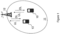
- Fig. 1 is a schematic overview depicting a wireless communication network 1.
- the wireless communication network 1 comprises one or more RANs and one or more CNs.
- the wireless communication network 1 may use a number of different technologies, such as Long Term Evolution (LTE), LTE-Advanced, Wideband Code Division Multiple Access (WCDMA), Global System for Mobile communications/Enhanced Data rate for GSM Evolution (GSM/EDGE), Worldwide Interoperability for Microwave Access (WiMax), or Ultra Mobile Broadband (UMB), just to mention a few possible implementations.
- LTE Long Term Evolution
- WCDMA Wideband Code Division Multiple Access
- GSM/EDGE Global System for Mobile communications/Enhanced Data rate for GSM Evolution
- WiMax Worldwide Interoperability for Microwave Access
- UMB Ultra Mobile Broadband
- the wireless communication network 1 is exemplified herein as an LTE network.
- a first receiving node 10 also known as a wireless device, mobile station, a user equipment and/or a wireless terminal, communicates via a Radio Access Network (RAN) to one or more core networks (CN).
- RAN Radio Access Network
- CN core networks
- receiving node is a non-limiting term which means any wireless terminal, user equipment, Machine Type Communication (MTC) device, a Device to Device (D2D) terminal, or a node, e.g. a smart phone, a laptop, a mobile phone, a sensor, a relay, a mobile tablet or even a small base station communicating within respective cell.
- MTC Machine Type Communication
- D2D Device to Device
- node e.g. a smart phone, a laptop, a mobile phone, a sensor, a relay, a mobile tablet or even a small base station communicating within respective cell.
- the wireless communication network 1 covers a geographical area which is divided into cell areas, e.g. a cell 11 being served by a transmitting node 12.
- the transmitting node 12 may also be referred to as a radio base station and e.g. a NodeB, an evolved Node B (eNB, eNode B), a base transceiver station, Access Point Base Station, base station router, or any other network unit capable of communicating with a user equipment within the cell served by the radio base station depending e.g. on the radio access technology and terminology used.
- the transmitting node 12 may serve one or more cells, such as the cell 11.
- a cell is a geographical area where radio coverage is provided by radio base station equipment at a base station site or at remote locations in Remote Radio Units (RRU).
- RRU Remote Radio Units
- the cell definition may also incorporate frequency bands and radio access technology used for transmissions, which means that two different cells may cover the same geographical area but using different frequency bands.
- Each cell is identified by an identity within the local radio area, which is broadcast in the cell. Another identity identifying the cell 11 uniquely in the whole wireless communication network 1 is also broadcasted in the cell 11.
- the transmitting node 12 communicates over the air or radio interface operating on radio frequencies with the receiving node 10 within range of the transmitting node 12.
- the receiving node 10 transmits data over the radio interface to the transmitting node 12 in Uplink (UL) transmissions and the transmitting node 12 transmits data over an air or radio interface to the first receiving node 10 in Downlink (DL) transmissions.
- the transmitting node 12 may also communicate with a second receiving node 13 in the cell 11.
- the second receiving node 13 may be a wireless device, mobile station, a user equipment and/or a wireless terminal, communicates via a Radio Access Network (RAN) to one or more core networks (CN).
- RAN Radio Access Network
- CN core networks
- the second receiving node 13 is a legacy terminal.
- the illustrated embodiments is only an example and it may be the other way around i.e. the transmitting node 12 may be a wireless device and the first receiving node 10 may be a radio base station.
- the transmitting node 12 comprises a number of transmit antennas being more than one and transmits at least one burst of energy to one or more receiving nodes, e.g. the first and second receiving node.
- the at least one burst of energy carries a payload for the second receiving node 13 and/or the first receiving node 10.
- the transmitting node determines a shift, for one or more transmit antennas of the transmit antennas, in one or more signal characteristics of a burst of energy of the at least one burst of energy.
- the shift indicates one or more additional information bits, in addition to the payload, for the first receiving node 10.
- the transmitting node 12 then transmits, over the one or more transmit antennas, the burst of energy of the at least one burst of energy with the shift in the signal characteristic/s.
- the burst of energy further carries the payload to one or more receiving nodes in the wireless communication network 1.
- the first receiving node 10 receives the burst of energy from the transmitting node 12 and then detects the shift in one or more signal characteristics of the received burst of energy compared to a reference signal characteristic known to the first receiving node 10. The first receiving node 10 determines, based on the detected shift, the one or more additional information bits intended for the first receiving node 10, of the burst of energy.
- Embodiments apply to multi-antenna wireless systems that transmit packets or bursts of energy, such as WiFi (IEEE 802.11) or GSM.
- the embodiments enable the robust transmission of extra or additional information bits, in addition to the normal payload carried by the packets or bursts of energy.
- extra information bits may be used to convey e.g. signaling and/or control information.
- coded or uncoded bits are mapped to complex-valued symbols, which in turn are mapped to code matrices by means of a space-time block code.
- the number of rows in the code matrices is equal to the number of transmit antennas.
- a column of a code matrix is picked for every burst of energy to be transmitted.
- Each entry in such column is a complex number with e.g. an amplitude and a phase.
- the phase and/or amplitude of the signals in each transmitter chain are shifted, according to the phase/amplitudes in the column of the code matrix.
- the phase/amplitude changes are applied to the whole packet or burst of energy.
- one column of a code matrix is transmitted during every burst of energy.
- the baud rate is much slower than the baud rate of the underlying system, which typically transmits hundreds or thousands of symbols per burst of energy or packet.
- the first receiving node 10 utilizes the fact that some signal part or parts, e.g. training sequence or symbol, of the transmitted signal are known in advance at the first receiving node 10.
- some signal part or parts e.g. training sequence or symbol
- the burst of energy starts with a known preamble comprising a Short Training Symbol (STF) and a Long Training Symbol (LTF).
- STF Short Training Symbol
- LTF Long Training Symbol
- a GSM burst of energy contains a known training sequence, inserted as a midamble.
- TX Transmitting
- RX Receiving
- the transmitting node 12 and/or the first receiving node 10 being an Internet of Things device being stationary at certain locations, or when the variations can be predicted/compensated, between bursts of energy, the channel, as experienced by the transmitted code matrices, depends on both the actual propagation channel and the known training or pilot symbols. The dependence upon the pilot symbols will be described in detail below. Since the additional information bits are spread over time and space, large diversity and processing gains are obtained, making the transmission scheme very robust. E.g. when the first receiving node 10 may be a sensor in a cellar with a large interfered transmission path, but with a stationary channel i.e. does not vary or changes very slow, the first receiving node 10 may not receive the payload but detects the shift and thus receives the additional information bits.
- Space-time block coding is a technique used in wireless communications to transmit multiple copies of a data stream across a number of transmit antennas and to exploit the various received versions of the data, at the first receiving node 10, to improve the reliability of data-transfer.
- One or more of the received copies are used to correctly decode the received signal.
- Copies of the received signal may be combined, at the first receiving node 10, to extract as much information from each of them as possible.
- any diversity code e.g. a space-time block code, any symbol constellation, and with any number of transmit and receive antennas.
- STBC Space-time block codes
- the set of 2x2 code matrices is of the form
- Differential space-time block codes are useful in practice because decoding does not require channel estimation.
- the Alamouti code may be easily adapted to construct a differential space-time block code as follows.
- the simplest space-time trellis code is transmit diversity, i.e. transmit with a delay between the transmit antennas.
- transmit diversity i.e. transmit with a delay between the transmit antennas.
- FFT Fast Fourier Transform
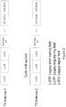
- FIG. 2 illustrates the packet format in 802.11ac packets.
- the IEEE standard 802.11ac will be used to exemplify the embodiments herein. However, embodiments are applicable to all amendments of 802.11 that support transmit diversity, such as 802.11n or 802.11ah.
- All 802.11ac packets start with some known training sequences in fields, called the Legacy Short Training Field (L-STF) and the Legacy Long Training Field (L-LTF), followed by a Legacy Signal Field (L-SIG).
- the packet format further comprises Very High Throughput Signal A1 (VHT-SIG-A1) to Very High Throughput Signal B (VHT-SIG-B) fields and also a Very High Throughput Data (VHT-data) field.
- VHT-SIG-A1 Very High Throughput Signal A1
- VHT-SIG-B Very High Throughput Signal B
- VHT-data Very High Throughput Data
- the transmitting node 12 for transmitting at least one burst of energy to one or more receiving nodes in the wireless communication network 1 according to some embodiments will now be described with reference to a flowchart depicted in Figure 3 .
- the actions do not have to be taken in the order stated below, but may be taken in any suitable order. Actions performed in some embodiments are marked with dashed boxes.
- the transmitting node 12 comprises as stated above a number of transmit antennas, e.g. four transmit antennas, being more than one.
- the at least one burst of energy carries a payload for one or more receiving nodes, e.g. the second receiving node 13.
- a concept of a super-channel for information transfer i.e.
- the one or more additional information bits, to a first receiving node 10, on an existing channel utilizing non-information bearing signal characteristics or parameters, i.e. the shift in one or more signal characteristics, may be used herein and partially generalize the concept to multi-antenna systems.
- Embodiments herein cover e.g. Multiple Input Multiple Output (MIMO) systems, and a narrow class of modulations.
- MIMO Multiple Input Multiple Output
- Embodiments herein may be applied to transmitting nodes in wireless communication networks with multiple transmit antennas, such as WiFi 802.11ac or GSM with transmit diversity.
- the transmitting node 12 and/or the first receiving node 10 may be an Internet of Things device.
- the transmitting node 12 may transmit configuration to one or more receiving nodes comprising information regarding a channel carrying the bursts of energy.
- the information may comprise radio frequency, a set of timeslots used, a training sequence code and/or modulation used, and/or information regarding how the one or more additional information bits are mapped to the shift in the one or more signal characteristics.
- the transmitting node 12 determines a shift, for one or more transmit antennas, in one or more signal characteristics of a burst of energy of the at least one burst of energy.
- the shift indicates one or more additional information bits, in addition to the payload, for the first receiving node 10.
- the determined shift in one or more signal characteristics of the burst of energy may be realized by changing a timing, frequency, amplitude and/or phase of the burst of energy.
- the determined shift may be relative to a previous burst of energy.
- the transmitting node 12 may map the one or more additional information bits to a code matrix by means of a diversity code.
- the one or more additional information bits may be mapped to a complex valued symbol, which complex valued symbol is mapped to the code matrix.
- the code matrix comprises a number of rows that is equal to the number of transmit antennas of the transmitting node 12 and a number of columns.
- the diversity code may be a space-time block code, a differential space-time code and/or similar.
- the transmitting node 12 may apply respectively for each transmit antenna out of the number of transmit antennas, the determined shift in one or more signal characteristics of the burst of energy, for carrying the one or more additional information bits, according to an entry of a column in the matrix.
- Each entry in the column is a complex number with one or more signal characteristics.
- the transmitting node 12 transmits, over the one or more transmit antennas, the burst of energy of the at least one burst of energy with the shift in the one or more signal characteristics, and carrying the payload to one or more receiving nodes in the wireless communication network 1.
- Two bursts may have different payloads and a burst may be transmitted over a plurality of transmit antennas or a plurality of bursts may be transmitted over a respective transmit antenna or on different transmit antennas.
- the burst of energy comprises a signal part, which signal part is known to the first receiving node 10.
- the payload may be transmitted to the second receiving node 13 and the one or more additional information bits may be transmitted to the first receiving node 10.
- the one or more additional information bits may be used to convey control signalling, system information, in-band signalling, user plane data, buffer status and/or device capability, of the transmitting node 12.
- the one or more additional information bits may be transparent to the second receiving node 13.
- the transmitting node 12 determines one or more shifts in one or more signal characteristics of a plurality of bursts of energy, which one or more shifts indicates the one or more additional information bits.
- the transmitting node 12 may then transmit the plurality of bursts of energy in sequence.
- the additional information bits are mapped to a sequence of X bursts for each transmit antenna.
- the determined shift may be added to the burst of energy that is already coded using a diversity code on symbol level.
- the payload is, at the transmitting node 12, encoded, modulated and mapped to the transmit antennas according to a wireless standard.
- SU-MIMO, MU-MIMO, and any number of space or space-time streams may be used.
- an STBC being a diversity code, may be used to map the additional information bits to code matrices.
- the code matrices have as many rows as there are transmit antennas. For each burst of energy or packet, a column of a code matrix is chosen. The phase and/or amplitude of the burst transmitted through a first antenna are shifted according to the phase and/or amplitude of the first entry in the chosen column of the code matrix. The procedure is repeated for all transmit antennas.
- phase and/or amplitude of the burst of energy transmitted through a second antenna are shifted according to the phase and/or amplitude of the second entry in the chosen column of the code matrix.
- the same procedure is applied to the bursts of energy transmitted through the other antennas.
- one column of a code matrix is transmitted with every burst of energy.
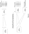
- the transmitting node 12 sends additional information bits, coded or uncoded bit/s, to the same receiving node or to a receiving node different from the receiving nodes in the case of MU-MIMO, for which the payload is intended. See Figure 4 for an illustration.
- four packets are transmitted from a transmitting node denoted 'STA 1', being an example of the transmitting node 12, to a receiving node 'STA 2' being an example of the first receiving node 10.
- Embodiments herein allow additional four additional bits, '1001' in this example, to be transmitted in parallel with the four packets to the receiving node STA 2.
- the packets and the additional information bits have different destinations, STA 2 and STA 3 respectively.
- the STA 2 is an example of the second receiving node 13 receiving the payload and the STA 3 is an example of the first receiving node 10 receiving the additional information bits.
- STA 2 is a legacy node not being aware that the bit sequence, the additional information bits, '1001' is also being transmitted.
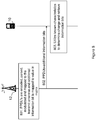
- Figure 5 and Figure 6 illustrate how to modify 802.11ac and GSM/EDGE transmitters according to the embodiments herein.
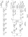
- Figure 7 shows in detail actions 303 and 304 above. Block diagram of transmitter processing according to embodiments, for a transmitter chain with N transmit antennas. This Figure 7 expands the dashed boxes in Figure 5 and Figure 6 .
- an 802.11ac transmitter with n TX antennas may comprise an Aggregated Mac Protocol Data Unit (A-MPDU) 501, an append Medium Access control (MAC) padding block 502, an append physical (PHY) padding block 503, and a prepend service field block 504.
- the transmitter may comprise a scrambler 505, a binary convolutional code (BCC) encoder parser 506, a plurality of append tail, encoder and puncture blocks 507a, ... , and 507n, a stream parser 508, a plurality of BCC interleaver blocks 509a, ... , and 509n, a plurality of constellation mapper blocks 510a, ...
- A-MPDU Aggregated Mac Protocol Data Unit
- MAC Medium Access control
- PHY physical
- the transmitter may comprise a scrambler 505, a binary convolutional code (BCC) encoder parser 506, a plurality of append tail, encoder and punct
- STBC/SFBC space time/frequency block coding
- CSD cyclical shift diversity
- IDFT Inverse Discrete Fourier transform
- GI insert guard interval
- RF analog radio frequency
- the transmitter may comprise an STBC block 516 that operates on bursts also referred to as packets.
- the STBC block 516 comprises a STBC 517 but also a plurality of phase shift and/or Amplitude change blocks 518a....518n.
- the STBC block 516 applies a shift in phase and/or amplitude according to a known scheme thereby transferring additional information bit/s to a receiver that also is aware of the known scheme.
- the dashed box contains the functionality introduced by embodiments herein.
- FIG. 6 shows an example of an GSM/EDGE transmitter with two Transmit (TX) antennas, modified according to the invention.
- the dashed box contains the functionality introduced by embodiments herein.
- the transmitter may comprise a channel coding and interleaving block 601, a symbol mapping block 602, and a burst formatting block 603 fed with a training sequence 604.
- the transmitter may further comprise a pulse shaping block 605, a delay block 606 for the second TX antenna, and two Analog and RF blocks 607, 608.
- the transmitter according to embodiments herein may comprise a STBC block 609 that operates on bursts of energy.
- the STBC block 609 comprises a STBC 610 but also two phase shift and/or Amplitude change blocks 611, 612.
- the STBC block 609 applies a shift in phase and/or amplitude according to a known scheme thereby transferring the additional information bit/s to a receiver that also is aware of the known scheme.
- Figure 7 is an example of the STBC block 516 and STBC block 609 for n transmit antennas.
- One or more information bits are fed into a symbol mapping block 701, mapping the one or more additional information bits to a complex valued symbol.
- the complex valued symbol is mapped to a code matrix X by means of a diversity code e.g. an STBC.
- the code matrix X is generated in a space time encoder 702 and comprises a number of rows that is equal to the number of transmit antennas and a number of columns.
- a column of the code matrix X is picked for every burst of energy p to be transmitted in a pick block 703. Each entry in such column is a complex number with e.g. an amplitude and a phase.
- phase and/or amplitude of the baseband signals in each transmitter chain are shifted in shift blocks 704a, 704b, ...704n, according to the phase/amplitudes in the column of the code matrix.
- the phase/amplitude changes are applied to the whole packet or burst. Hence, one column of a code matrix is transmitted during every burst of energy.
- detection is based on the known signal part such as training or pilot symbols contained in the transmitted signals.
- the receiver algorithms will be described for the simple but relevant case of two transmit antennas and one receive antenna.
- the STBC receiver algorithms described in reference Space-Time Block Coding for Wireless Communications, Erik G. Larsson and Petre Stoica, Cambridge University Press 2008 do not apply to the embodiments herein. But the STBC receiver algorithms described may be extended to cover the space-time codes introduced in embodiments herein, as shown below.
- the discrete equivalent channel from antenna k to the receive antenna is denoted h k and it is assumed that it is represented by a Finite Impulse Response (FIR) filter with L + 1 taps.
- FIR Finite Impulse Response
- w ( p,n ) are noise samples, independent and identically Gaussian distributed
- the channel as experienced by the code matrices, consists of the taps u m ( n ), which in turn depend on both the propagation channel and the known pilot symbols. Notice also that even though the channel is time dispersive, the slow signaling rate makes the channel as experienced by the code matrices, free of inter-symbol interference.
- the maximum likelihood estimator of the transmitted code matrix is, using the notation above,
- q n ⁇ R QPSK , n 1,2.
- Coherent detection is not necessary when differential space-time codes are used. In particular, it is not necessary to estimate the channel.
- Equation (11)-(18) The model used is the same as in Equations (11)-(18) above. However, this time it is not necessary to know the channel nor are the training sequences used explicitly. It is only necessary to know which part of the received signal corresponds to the training sequences.
- R p UX p + W p , where p is the packet/burst number.
- Non-coherent maximum likelihood detection requires the minimization of the following quantity ⁇ R p + 2 ⁇ UX p + 2 ⁇ 2 + ⁇ R p ⁇ UX p ⁇ 2 .
- this last expression is equal to ⁇ R p + 2 ⁇ UX p G p + 2 ⁇ 2 + ⁇ R p ⁇ UX p ⁇ 2 .
- q n ⁇ R QPSK , n 1,2 .
- Embodiments will be exemplified with the aid of an IEEE 802.11ac wireless system which employs two transmit antennas and one receive antenna.
- the transmitting node 12 sends 4 PPDU's to the first receiving node 10.
- the illustrated embodiment herein is used to transmit 4 additional information bits to the first receiving node, or alternatively, to send 4 PPDU's to the second receiving node 13. These additional information bits may be used for control signaling, management or other purposes.
- the transmitting node 12 the 4 PPDU's are encoded, parsed, modulated and mapped to the transmit antennas according to the 802.11ac standard. In this example it is assumed that the Alamouti space-time code and cyclic shift diversity as described in the 802.11ac are applied.
- the baseband signals are defined as ⁇ y 1 ( t,p ): 0 ⁇ t ⁇ T p , 0 ⁇ p ⁇ 3 ⁇ and ⁇ y 2 ( t,p ): 0 ⁇ t ⁇ T, 0 ⁇ p ⁇ 3 ⁇ .
- the subscripts 1 and 2 refer to the transmit antenna, p is the PPDU or packet/burst number, and T p is the duration of the p -th PPDU.
- the variable time t may be discrete or continuous, since embodiments herein may be applied in the digital domain to a digital baseband signal, or in the analog domain to an analog baseband signal.
- Action 802. In addition to the 4 PPDU's, the additional information bits '1001',see action 305, may be transmitted using a differential Alamouti code and a QPSK constellation, as described in Section above.
- the encoding process example of the actions 303 and 304 above, is the following.
- Action 802 is illustrated in Figure 9 .
- the space-time code gives a spatial diversity gain.
- the 4 additional information bits are very robustly transmitted.
- Code Matrices X(0) and X(2) are used, not matrix X(1), to shift the baseband signals.
- the 4 additional information bits may be mapped to a sequence of X packets or bursts of energy for each transmit antenna.
- the method actions in the first receiving node 10 for receiving at least one burst of energy from the transmitting node 12 in the wireless communication network 1 will now be described with reference to a flowchart depicted in Figure 10 .
- the actions do not have to be taken in the order stated below, but may be taken in any suitable order. Actions performed in some embodiments are marked with dashed boxes.
- the at least one burst of energy carries a payload for one or more receiving nodes.
- the transmitting and/or the first receiving node may be an Internet of Things device.
- the first receiving node 10 may determine a radio channel, carrying the burst of energy, as a radio channel with stationary channel characteristics or a radio channel with channel characteristics varying in a manner known or predicted at the first receiving node 10.
- the first receiving node 10 may configure the first receiving node 10 for receiving the one or more additional information bits by receiving configuration from the transmitting node 12.
- the configuration may comprise information regarding a channel carrying the bursts of energy, which information comprises radio frequency, a set of timeslots used, a training sequence code and/or modulation used, and/or information regarding how the additional information bits are mapped to the shift in the one or more signal characteristics.
- the first receiving node 10 receives a burst of energy of the at least one burst of energy from the transmitting node 12.
- the first receiving node 10 detects a shift in one or more signal characteristics of the received burst of energy compared to a reference signal characteristic known to the first receiving node.
- the reference signal characteristic may be a signal part of the burst of energy and the first receiving node 10 may detect the shift on at least a part of the signal part of the burst of energy.
- the burst of energy comprises payload and a non-information bearing part being the signal part.
- the detection of the "additional information bits" may be done solely based on the non-information bearing part of the signal, hence the first receiving node 10 monitors the part of the received signal corresponding to the signal part in order to detect the additional information bits.
- the detected shift in one or more signal characteristics of the burst of energy may be realized by detecting a change in timing, frequency, amplitude and/or phase of the burst of energy.
- the detected shift may be relative to a previous burst of energy.
- the first receiving node 10 determines one or more additional information bits, in addition to the payload, intended for the first receiving node 10, of the burst of energy based on the detected shift.
- the received burst of energy of the at least one burst of energy may be decoded as a diversity code e.g. when the first receiving node 10 receives a number of bursts of energy.
- the diversity code may be a space-time block code, a differential space-time code and/or similar.
- the one or more additional information bits may be to convey control signalling, system information, in-band signalling, user plane data, buffer status and/or device capability, of the transmitting node 12.
- Figure 11 is a block diagram depicting the transmitting node 12 and the first receiving node 10 configured to perform the methods herein.
- the transmitting node 12 for transmitting at least one burst of energy to one or more receiving nodes, e.g. the first and second receiving nodes, in the wireless communication network 1 is provided herein.
- the transmitting node 12 comprises a number of transmit antennas being more than one and the at least one burst of energy is configured to carry a payload for one or more receiving nodes.
- the transmitting node 12 may comprise processing circuitry 1301 and/or a determining module 1302.
- the transmitting node 12, the processing circuitry 1301 and/or the determining module 1302 may be configured to determine a shift, for one or more transmit antennas, in one or more signal characteristics of a burst of energy of the at least one burst of energy.
- the shift indicates one or more additional information bits, in addition to the payload, for the first receiving node 10.
- the transmitting node 12, the processing circuitry 1301 and/or the determining module 1302 may further be configured to determine one or more shifts in one or more signal characteristics of a plurality of bursts of energy, which one or more shifts indicates the one or more additional information bits and also being configured to transmit the plurality of bursts of energy in sequence.
- the determined shift may be relative to a previous burst of energy.
- the transmitting node 12 may comprise a transmitting module 1303.
- the transmitting node 12, the processing circuitry 1301 and/or the transmitting module 1303 may be configured to transmit over the one or more transmit antennas, the burst of energy of the at least one burst of energy with the shift in the one or more signal characteristics, and carrying the payload to one or more receiving nodes in the wireless communication network 1.
- the burst of energy may comprise a signal part, e.g. a training sequence, which signal part is known to the first receiving node 10.
- the transmitting node 12, the processing circuitry 1301 and/or the transmitting module 1303 may be configured to transmit the payload to the second receiving node 13 and to transmit the one or more additional information bits to the first receiving node 10.
- the payload may also be transmitted to the first receiving node 10.
- the one or more additional information bits may then be transparent to the second receiving node 13.
- the transmitting node 12, the processing circuitry 1301 and/or the transmitting module 1303 may be configured to transmit configuration to one or more receiving nodes comprising information regarding a channel carrying the bursts of energy.
- the information comprises radio frequency, a set of timeslots used, a training sequence code and/or modulation used, and/or information regarding how the one or more additional information bits are mapped to the shift in the one or more signal characteristics.
- the transmitting node 12 may comprise a mapping module 1304.
- the transmitting node 12, the processing circuitry 1301 and/or the mapping module 1304 may be configured to map the one or more additional information bits to a code matrix by means of a diversity code, the code matrix comprises a number of rows that is equal to the number of transmit antennas of the transmitting node 12 and a number of columns.
- the diversity code may be a space-time block code, a differential space-time code and/or similar.
- the transmitting node 12 may comprise an applying module 1305.
- the transmitting node 12, the processing circuitry 1301 and/or the applying module 1305 may be configured to apply respectively for each transmit antenna out of the number of transmit antennas, the determined shift in one or more signal characteristics of the burst of energy, for carrying the one or more additional information bits, according to an entry of a column in the matrix, wherein each entry in the column is a complex number with one or more signal characteristics.
- the transmitting node 12 may comprise a realizing module 1306.
- the transmitting node 12, the processing circuitry 1301 and/or the realizing module 1306 may be configured to realize the determined shift in one or more signal characteristics of the burst of energy by changing a timing, frequency, amplitude and/or phase of the burst of energy.
- the transmitting node 12 may comprise an adding module 1307.
- the transmitting node 12, the processing circuitry 1301 and/or the adding module 1307 may be configured to add the determined shift to the burst of energy that is already coded using a diversity code on symbol level.
- the one or more additional information bits may be to convey control signalling, system information, in-band signalling, user plane data, buffer status and/or device capability, of the transmitting node 12.
- the transmitting node 12 and/or the first receiving node 10 may be an Internet of Things device.
- the methods according to the embodiments described herein for the transmitting node 12 are respectively implemented by means of e.g. a computer program 1308 or a computer program product, comprising instructions, i.e., software code portions, which, when executed on at least one processor, cause the processor circuitry o means to carry out the actions described herein, as performed by the transmitting node 12.
- the computer program 1308 may be stored on a computer-readable storage medium 1309, e.g. a disc or similar.
- the computer-readable storage medium 1309, having stored thereon the computer program 1308, may comprise the instructions which, when executed on the processing circuitry 1301, cause the processing circuitry 1301 to carry out the actions described herein, as performed by the transmitting node 12.
- the computer-readable storage medium 1309 may be a non-transitory computer-readable storage medium.
- the transmitting node 12 may comprise a memory 1310 configured to store shifts, matrices, data, additional informational bits, payload, applications to perform the method herein and/or similar.
- the transmitting node 12 may comprise a table or similar mapping the additional information bits to information, e.g. bits '01' means a certain transmission mode or operational mode.
- the first receiving node 10 for receiving at least one burst of energy from the transmitting node 12 in the wireless communication network 1 is herein provided,
- the at least one burst of energy is configured to carry a payload for one or more receiving nodes, e.g. the second receiving node 13 and/or the first receiving node 10,
- the first receiving node 10 may comprise processing circuitry 1401 and/or a receiving module 1402.
- the first receiving node 10, the processing circuitry 1401 and/or the receiving module 1402 may be configured to receive a burst of energy of the at least one burst of energy from the transmitting node 12.
- the first receiving node 10, the processing circuitry 1401 and/or the receiving module 1402 may be configured to receive a plurality of bursts of energy in sequence.
- the first receiving node 10 may comprise a detecting module 1403.
- the first receiving node 10, the processing circuitry 1401 and/or the detecting module 1403 may be configured to detect a shift in one or more signal characteristics of the received burst of energy compared to a reference signal characteristic known to the first receiving node 10.
- the reference signal characteristic may be a signal part of the burst of energy and the first receiving node 10, the processing circuitry 1401 and/or the detecting module 1403 may be configured to detect the shift on at least a part of the signal part of the burst of energy.
- the first receiving node 10, the processing circuitry 1401 and/or the detecting module 1403 may be configured to detect the shift relative to a previous burst of energy.
- the first receiving node 10 may comprise a determining module 1404.
- the first receiving node 10, the processing circuitry 1401 and/or the determining module 1404 may be configured to determine one or more additional information bits, in addition to the payload, intended for the first receiving node 10, of the burst of energy based on the detected shift.
- the one or more additional information bits may be to convey control signalling, system information, in-band signalling, user plane data, buffer status and/or device capability, of the transmitting node 12.
- the first receiving node 10 may comprise a table mapping the additional bits to information e.g. a certain bit or bits indicates a certain system information, an operational mode or similar.
- the first receiving node 10, the processing circuitry 1401 and/or the determining module 1404 may be configured to determine a radio channel, carrying the burst of energy, as a radio channel with stationary channel characteristics or a radio channel with channel characteristics varying in a manner known or predicted at the first receiving node 10.
- the first receiving node 10 may comprise a decoding module 1405.
- the first receiving node 10, the processing circuitry 1401 and/or the decoding module 1405 may be configured to decode the received burst of energy of the at least one burst of energy as a diversity code.
- the diversity code may be a space-time block code, a differential space-time code and/or similar.
- the first receiving node 10 may comprise a realizing module 1406.
- the first receiving node 10, the processing circuitry 1401 and/or the realizing module 1406 may be configured to realize the detected shift in one or more signal characteristics of the burst of energy by detecting a change in timing, frequency, amplitude and/or phase of the burst of energy.
- the first receiving node 10 may comprise a configuring module 1407.
- the first receiving node 10, the processing circuitry 1401 and/or the configuring module 1407 may be configured to configure the first receiving node 10 for receiving the one or more additional information bits by receiving configuration from the transmitting node 12.
- the configuration may comprise information regarding a channel carrying the bursts of energy, which information comprises radio frequency, a set of timeslots used, a training sequence code and/or modulation used, and/or information regarding how the additional information bits are mapped to the shift in the one or more signal characteristics.
- the transmitting node 12 and/or the first receiving node 10 may be an Internet of Things device.
- the methods according to the embodiments described herein for the first receiving node 10 are respectively implemented by means of e.g. a computer program 1408 or a computer program product, comprising instructions, i.e., software code portions, which, when executed on the processing circuitry, cause the processor circuitry or means to carry out the actions described herein, as performed by the first receiving node 10.
- the computer program 1408 may be stored on a computer-readable storage medium 1409, e.g. a disc or similar.
- the computer-readable storage medium 1409, having stored thereon the computer program 1408, may comprise the instructions which, when executed on the processing circuitry 1401, cause the processing circuitry 1401 to carry out the actions described herein, as performed by the first receiving node 10.
- the computer-readable storage medium 1409 may be a non-transitory computer-readable storage medium.
- the first receiving node 10 may comprise a memory 1410 configured to store shifts, matrices, data, additional informational bits, payload, mapping of the bits to information, applications to perform the method herein and/or similar.
- a so called super-channel When a so called super-channel is operated in a wireless communication network, e.g. WiFi or GSM, as described in above, possibly extended with a transmit diversity scheme according to the embodiments herein, it is necessary for the receiver(s) of the super-channel to know where to find the super-channel, its characteristics, and the characteristics of the underlying channel.
- this information may include the radio frequency, the set of timeslots used, the training sequence code(s) and modulation(s) used on the underlying channel, whether a transmit diversity scheme, according to embodiments herein, is used, etc.
- This information may be broadcast in the cell from the transmitting node 12. It may also be conveyed to the first receiving node 10 in a dedicated signaling message following an access attempt by the first receiving node 10.
- the information may be broadcast in a System Information (SI) message on the Broadcast Control Channel (BCCH) or sent in a dedicated message, or dedicated part of a message, on the Access Grant Channel (AGCH).
- SI System Information
- BCCH Broadcast Control Channel
- AGCH Access Grant Channel
- the transmitting node 12 transmits a signal to the first receiving node 10 over a radio channel with characteristics carrying phase and amplitude information to be estimated at the first receiving node 10.
- the transmitting node determines a change in signal characteristics such as amplitude and/or phase and/or time shift variation relative to reference characteristics be added to the signal.
- the transmitting node then transmits the signal to the first receiving node 10, wherein the changed signal characteristics carries information for the first receiving node 10.
- the information or one or more additional information bits may be transmitted to the first receiving node not able to receive the payload but able to determine shift or not, resulting in a more redundant transmission enabling reception in e.g. a cellar or similar.
- the channel has stationary channel characteristics or is a radio channel with channel characteristics varying in a manner known or predicted at the first receiving node 10.
- Phase/amplitude shifts may be picked from the columns of space-time code matrices. These phase/amplitude shifts are information bearing, and are applied to the packets/bursts in a multi-antenna wireless system, such as GSM or IEEE 802.11.
- known training sequences, together with channel estimates, are used to derive a channel for the space-time code matrices, from which both coherent and non-coherent optimum receivers are also derived.
- the information bearing space-time code matrices form a very robust, low rate signaling channel, on top of the normal space-time transmissions used in the multi-antenna wireless system. This type of signaling does not degrade the performance of legacy devices utilizing the underlying wireless system.
- ASIC application-specific integrated circuit
- Several of the functions may be implemented on a processor shared with other functional components of a transmitting/receiving node, for example.
- processors or “controller” as used herein does not exclusively refer to hardware capable of executing software and may implicitly include, without limitation, digital signal processor (DSP) hardware, read-only memory (ROM) for storing software, random-access memory for storing software and/or program or application data, and non-volatile memory.
- DSP digital signal processor
- ROM read-only memory
- RAM random-access memory
- non-volatile memory non-volatile memory
Landscapes
- Engineering & Computer Science (AREA)
- Signal Processing (AREA)
- Computer Networks & Wireless Communication (AREA)
- Mobile Radio Communication Systems (AREA)
- Radio Transmission System (AREA)
Claims (9)
- Verfahren, das in einem Sendeknoten (12) durchgeführt wird, zum Senden mindestens eines Energiebursts an einen oder mehrere Empfangsknoten (10, 13) in einem drahtlosen Kommunikationsnetzwerk (1), wobei der Sendeknoten (12) eine Anzahl von Sendeantennen umfasst, wobei es sich um mehr als eine handelt, und wobei der mindestens eine Energieburst eine Nutzlast für einen oder mehrere Empfangsknoten (10, 13) überträgt, wobei das Verfahren umfasst:- Bestimmen (302) für eine oder mehrere Sendeantennen einer Verschiebung einer oder mehrerer Signalcharakteristiken eines Energiebursts des mindestens einen Energiebursts, welche Verschiebung ein oder mehrere zusätzliche Informationsbits zusätzlich zu der Nutzlast angibt;- Abbilden (303) des einen oder der mehren zusätzlichen Informationsbits auf eine Code-Matrix mittels eines Diversitätscodes, wobei die Code-Matrix eine Anzahl von Zeilen, die gleich der Anzahl von Sendeantennen des Sendeknotens (12) ist, und eine Anzahl von Spalten umfasst, und- jeweiliges Anwenden (304) für jede Sendeantenne aus der Anzahl von Sendeantennen der bestimmten Verschiebung einer oder mehrerer Signalcharakteristiken des Energiebursts zum Übertragen des einen oder der mehreren zusätzlichen Informationsbits gemäß einem Eintrag einer Spalte in der Matrix, wobei jeder Eintrag in der Spalte eine komplexe Zahl mit einer oder mehreren Signalcharakteristiken ist; und- Senden (305, 802) von Einträgen in einer Spalte der Code-Matrix mit jedem Energieburst des mindestens einen Energiebursts mit der Verschiebung der einen oder der mehreren Signalcharakteristiken über die eine oder die mehreren Sendeantennen und Übertragen der Nutzlast an den einen oder die mehreren Empfangsknoten (10, 13) im drahtlosen Kommunikationsnetzwerk (1).
- Verfahren nach Anspruch 1, wobei das Bestimmen (302) ein Bestimmen einer oder mehrerer Verschiebungen einer oder mehrerer Signalcharakteristiken einer Mehrzahl von Energiebursts umfasst, welche eine oder mehreren Verschiebungen das eine oder die mehreren zusätzlichen Informationsbits angeben, und das Senden ein Senden der Mehrzahl von Energiebursts der Reihe nach umfasst.
- Verfahren nach Anspruch 1 oder 2, wobei der Diversitätscode ein Raum-Zeit-Blockcode und/oder ein differenzieller Raum-Zeit-Code ist.
- Verfahren nach einem der Ansprüche 1 bis 3, wobei die bestimmte Verschiebung einer oder mehrerer Signalcharakteristiken des Energiebursts durch Ändern eines Takts, einer Frequenz, einer Amplitude und/oder einer Phase des Energiebursts realisiert wird.
- Verfahren nach einem der Ansprüche 1 bis 4, wobei der Energieburst einen Signalteil umfasst, welcher Signalteil einem ersten Empfangsknoten (10) des einen oder der mehreren Empfangsknoten (10, 13) bekannt ist.
- Verfahren nach einem der Ansprüche 1 bis 5, wobei die Nutzlast an einen zweiten Empfangsknoten (13) gesendet wird, und das eine oder die mehreren Informationsbits an den ersten Empfangsknoten (10) des einen oder der mehreren Empfangsknoten (10, 13) gesendet werden.
- Verfahren nach Anspruch 6, wobei das eine oder die mehreren zusätzlichen Informationsbits für den zweiten Empfangsknoten (13) transparent sind.
- Verfahren nach einem der Ansprüche 1 bis 7, ferner umfassend:- Senden (301) einer Konfiguration an einen oder mehrere Empfangsknoten, umfassend Informationen hinsichtlich eines Kanals, der die Energiebursts überträgt, welche Informationen Hochfrequenz, einen Satz von verwendeten Zeitschlitzen, einen verwendeten Trainingssequenzcode und/oder eine verwendete Modulation umfassen, und/oder Informationen hinsichtlich dessen, wie das eine oder die mehreren Informationsbits auf die Verschiebung der einen oder der mehreren Signalcharakteristiken abgebildet werden.
- Sendeknoten (12) zum Senden mindestens eines Energiebursts an einen oder mehrere Empfangsknoten (10, 13) in einem drahtlosen Kommunikationsnetzwerk (1), wobei der Sendeknoten (12) eine Anzahl von Sendeantennen umfasst, wobei es sich um mehr als eine handelt, und wobei der mindestens eine Energieburst zum Übertragen einer Nutzlast für einen oder mehrere Empfangsknoten (10, 13) ausgelegt ist, wobei der Sendeknoten (12) ausgelegt ist zum:Bestimmen für eine oder mehrere Sendeantennen einer Verschiebung einer oder mehrerer Signalcharakteristiken eines Energiebursts des mindestens einen Energiebursts, welche Verschiebung ein oder mehrere zusätzliche Informationsbits zusätzlich zu der Nutzlast angibt;Abbilden des einen oder der mehren zusätzlichen Informationsbits auf eine Code-Matrix mittels eines Diversitätscodes, wobei die Code-Matrix eine Anzahl von Zeilen, die gleich der Anzahl von Sendeantennen des Sendeknotens (12) ist, und eine Anzahl von Spalten umfasst, undjeweiliges Anwenden für jede Sendeantenne aus der Anzahl von Sendeantennen der bestimmten Verschiebung einer oder mehrerer Signalcharakteristiken des Energiebursts zum Übertragen des einen oder der mehreren zusätzlichen Informationsbits gemäß einem Eintrag einer Spalte in der Matrix, wobei jeder Eintrag in der Spalte eine komplexe Zahl mit einer oder mehreren Signalcharakteristiken ist; undSenden von Einträgen in einer Spalte der Code-Matrix mit jedem Energieburst des mindestens einen Energiebursts mit der Verschiebung der einen oder der mehreren Signalcharakteristiken über die eine oder die mehreren Sendeantennen und Übertragen der Nutzlast an den einen oder die mehreren Empfangsknoten (10, 13) im drahtlosen Kommunikationsnetzwerk (1).
Applications Claiming Priority (1)
| Application Number | Priority Date | Filing Date | Title |
|---|---|---|---|
| PCT/SE2014/051334 WO2016076768A1 (en) | 2014-11-11 | 2014-11-11 | Transmitting node, receiving node and methods performed therein |
Publications (2)
| Publication Number | Publication Date |
|---|---|
| EP3219036A1 EP3219036A1 (de) | 2017-09-20 |
| EP3219036B1 true EP3219036B1 (de) | 2019-06-19 |
Family
ID=51999491
Family Applications (1)
| Application Number | Title | Priority Date | Filing Date |
|---|---|---|---|
| EP14805381.2A Not-in-force EP3219036B1 (de) | 2014-11-11 | 2014-11-11 | Übertragungsknoten und darin durchgeführte verfahren |
Country Status (4)
| Country | Link |
|---|---|
| US (1) | US9935747B2 (de) |
| EP (1) | EP3219036B1 (de) |
| CN (1) | CN107078854B (de) |
| WO (1) | WO2016076768A1 (de) |
Families Citing this family (3)
| Publication number | Priority date | Publication date | Assignee | Title |
|---|---|---|---|---|
| US10733616B1 (en) * | 2016-10-20 | 2020-08-04 | Massachusets Mutual Life Insurance Company | Systems and methods for trigger based synchronized updates in a distributed records environment |
| JP6587781B2 (ja) * | 2017-06-15 | 2019-10-09 | 三菱電機株式会社 | 送信装置、受信装置および無線通信システム |
| JP7123607B2 (ja) * | 2018-04-09 | 2022-08-23 | シャープ株式会社 | ユーザ装置、制御装置、及び通信制御方法 |
Family Cites Families (13)
| Publication number | Priority date | Publication date | Assignee | Title |
|---|---|---|---|---|
| US20020110108A1 (en) * | 2000-12-07 | 2002-08-15 | Younglok Kim | Simple block space time transmit diversity using multiple spreading codes |
| US6748024B2 (en) | 2001-03-28 | 2004-06-08 | Nokia Corporation | Non-zero complex weighted space-time code for multiple antenna transmission |
| KR100987777B1 (ko) * | 2004-02-05 | 2010-10-13 | 삼성전자주식회사 | 에러의 전파를 방지하고 병렬 처리가 가능한 디코딩 방법및 그 디코딩 장치 |
| US8077592B2 (en) * | 2004-06-22 | 2011-12-13 | Intellectual Ventures I Llc | Packet processing systems and methods |
| GB2423675B (en) * | 2005-02-28 | 2009-08-19 | King S College London | Diversity transmitter and method |
| KR100817497B1 (ko) | 2006-03-10 | 2008-03-27 | 한국전자통신연구원 | 다중 안테나를 위한 심볼 생성 장치 및 방법 |
| US8144683B1 (en) * | 2007-11-29 | 2012-03-27 | Qualcomm Atheros, Inc. | High throughput fine timing |
| US8848816B2 (en) * | 2008-05-21 | 2014-09-30 | Qualcomm Incorporated | Method and apparatus for determining the spatial channels in a spatial division multiple access (SDMA)-based wireless communication system |
| US8488529B2 (en) * | 2011-01-05 | 2013-07-16 | Telefonaktiebolaget Lm Ericsson (Publ) | Efficient information mapping for transmission grants |
| JP5912026B2 (ja) * | 2011-10-20 | 2016-04-27 | 株式会社メガチップス | 通信装置および通信システム |
| US8995320B2 (en) * | 2012-04-16 | 2015-03-31 | Qualcomm Incorporated | Systems and methods of using space time block codes |
| US9398123B2 (en) * | 2013-05-03 | 2016-07-19 | Qualcomm Incorporated | Systems and methods for aggregation of physical protocol data units on a wireless network |
| US9300376B2 (en) * | 2013-07-05 | 2016-03-29 | Samsung Electronics Co., Ltd. | Transmitting apparatus, receiving apparatus, and control methods thereof |
-
2014
- 2014-11-11 US US14/408,999 patent/US9935747B2/en active Active
- 2014-11-11 CN CN201480083300.9A patent/CN107078854B/zh not_active Expired - Fee Related
- 2014-11-11 WO PCT/SE2014/051334 patent/WO2016076768A1/en active Application Filing
- 2014-11-11 EP EP14805381.2A patent/EP3219036B1/de not_active Not-in-force
Non-Patent Citations (1)
| Title |
|---|
| None * |
Also Published As
| Publication number | Publication date |
|---|---|
| WO2016076768A1 (en) | 2016-05-19 |
| CN107078854A (zh) | 2017-08-18 |
| CN107078854B (zh) | 2020-07-07 |
| US20160134398A1 (en) | 2016-05-12 |
| US9935747B2 (en) | 2018-04-03 |
| EP3219036A1 (de) | 2017-09-20 |
Similar Documents
| Publication | Publication Date | Title |
|---|---|---|
| US9088443B2 (en) | Channel estimation and interference cancellation for virtual MIMO demodulation | |
| US8774151B2 (en) | Closed-loop MIMO systems and methods | |
| US7660288B2 (en) | Radio communication device | |
| US8917784B2 (en) | Method and apparatus for constructing very high throughput long training field sequences | |
| US8982997B2 (en) | Signaling and channel estimation for uplink transmit diversity | |
| US20160380689A1 (en) | Method and apparatus of signal transmission and reception in a filter bank multiple carrier system | |
| US20140355626A1 (en) | Methods and devices for processing a data frame | |
| US9654308B2 (en) | Systems and methods for carrier frequency offset estimation for long training fields | |
| US20110107174A1 (en) | Method and apparatus for interchanging multipath signals in a sc-fdma system | |
| EP3172937B1 (de) | System und verfahren für ofdma-übertragung | |
| EP2386180A1 (de) | Ofdma-kommunikationssystem mit mehrfachem komponententrägrer | |
| US8503566B2 (en) | Method of transmitting multi-carrier signals in a multi-antenna system | |
| US20120219082A1 (en) | MIMO Wireless Communication Systems | |
| US9571140B2 (en) | Space-time coding for zero-tail spread OFDM system in a wireless network | |
| US20020193070A1 (en) | Radio transmitting apparatus and radio transmitting method | |
| EP2822191B1 (de) | Übertragungsvorrichtung, Empfangsvorrichtung und Steuerungsverfahren dafür | |
| EP3219036B1 (de) | Übertragungsknoten und darin durchgeführte verfahren | |
| CN101257468B (zh) | 一种多载波调制的子载波映射和逆映射的方法和装置 | |
| EP3544202B1 (de) | Vor-dft-referenzsignaleinblendung für einzelsymbol-stbc | |
| CN107634824B (zh) | 传输信号的方法和装置 | |
| KR20080010036A (ko) | 다중 안테나 통신시스템의 채널추정 장치 및 방법 |
Legal Events
| Date | Code | Title | Description |
|---|---|---|---|
| STAA | Information on the status of an ep patent application or granted ep patent |
Free format text: STATUS: THE INTERNATIONAL PUBLICATION HAS BEEN MADE |
|
| PUAI | Public reference made under article 153(3) epc to a published international application that has entered the european phase |
Free format text: ORIGINAL CODE: 0009012 |
|
| STAA | Information on the status of an ep patent application or granted ep patent |
Free format text: STATUS: REQUEST FOR EXAMINATION WAS MADE |
|
| 17P | Request for examination filed |
Effective date: 20170421 |
|
| AK | Designated contracting states |
Kind code of ref document: A1 Designated state(s): AL AT BE BG CH CY CZ DE DK EE ES FI FR GB GR HR HU IE IS IT LI LT LU LV MC MK MT NL NO PL PT RO RS SE SI SK SM TR |
|
| AX | Request for extension of the european patent |
Extension state: BA ME |
|
| DAX | Request for extension of the european patent (deleted) | ||
| STAA | Information on the status of an ep patent application or granted ep patent |
Free format text: STATUS: EXAMINATION IS IN PROGRESS |
|
| 17Q | First examination report despatched |
Effective date: 20180731 |
|
| GRAP | Despatch of communication of intention to grant a patent |
Free format text: ORIGINAL CODE: EPIDOSNIGR1 |
|
| STAA | Information on the status of an ep patent application or granted ep patent |
Free format text: STATUS: GRANT OF PATENT IS INTENDED |
|
| INTG | Intention to grant announced |
Effective date: 20190221 |
|
| GRAS | Grant fee paid |
Free format text: ORIGINAL CODE: EPIDOSNIGR3 |
|
| GRAA | (expected) grant |
Free format text: ORIGINAL CODE: 0009210 |
|
| STAA | Information on the status of an ep patent application or granted ep patent |
Free format text: STATUS: THE PATENT HAS BEEN GRANTED |
|
| AK | Designated contracting states |
Kind code of ref document: B1 Designated state(s): AL AT BE BG CH CY CZ DE DK EE ES FI FR GB GR HR HU IE IS IT LI LT LU LV MC MK MT NL NO PL PT RO RS SE SI SK SM TR |
|
| REG | Reference to a national code |
Ref country code: GB Ref legal event code: FG4D |
|
| REG | Reference to a national code |
Ref country code: CH Ref legal event code: EP |
|
| REG | Reference to a national code |
Ref country code: IE Ref legal event code: FG4D |
|
| REG | Reference to a national code |
Ref country code: DE Ref legal event code: R096 Ref document number: 602014048749 Country of ref document: DE |
|
| REG | Reference to a national code |
Ref country code: AT Ref legal event code: REF Ref document number: 1146863 Country of ref document: AT Kind code of ref document: T Effective date: 20190715 |
|
| REG | Reference to a national code |
Ref country code: NL Ref legal event code: MP Effective date: 20190619 |
|
| PG25 | Lapsed in a contracting state [announced via postgrant information from national office to epo] |
Ref country code: AL Free format text: LAPSE BECAUSE OF FAILURE TO SUBMIT A TRANSLATION OF THE DESCRIPTION OR TO PAY THE FEE WITHIN THE PRESCRIBED TIME-LIMIT Effective date: 20190619 Ref country code: SE Free format text: LAPSE BECAUSE OF FAILURE TO SUBMIT A TRANSLATION OF THE DESCRIPTION OR TO PAY THE FEE WITHIN THE PRESCRIBED TIME-LIMIT Effective date: 20190619 Ref country code: NO Free format text: LAPSE BECAUSE OF FAILURE TO SUBMIT A TRANSLATION OF THE DESCRIPTION OR TO PAY THE FEE WITHIN THE PRESCRIBED TIME-LIMIT Effective date: 20190919 Ref country code: FI Free format text: LAPSE BECAUSE OF FAILURE TO SUBMIT A TRANSLATION OF THE DESCRIPTION OR TO PAY THE FEE WITHIN THE PRESCRIBED TIME-LIMIT Effective date: 20190619 Ref country code: HR Free format text: LAPSE BECAUSE OF FAILURE TO SUBMIT A TRANSLATION OF THE DESCRIPTION OR TO PAY THE FEE WITHIN THE PRESCRIBED TIME-LIMIT Effective date: 20190619 Ref country code: LT Free format text: LAPSE BECAUSE OF FAILURE TO SUBMIT A TRANSLATION OF THE DESCRIPTION OR TO PAY THE FEE WITHIN THE PRESCRIBED TIME-LIMIT Effective date: 20190619 |
|
| REG | Reference to a national code |
Ref country code: LT Ref legal event code: MG4D |
|
| PG25 | Lapsed in a contracting state [announced via postgrant information from national office to epo] |
Ref country code: RS Free format text: LAPSE BECAUSE OF FAILURE TO SUBMIT A TRANSLATION OF THE DESCRIPTION OR TO PAY THE FEE WITHIN THE PRESCRIBED TIME-LIMIT Effective date: 20190619 Ref country code: GR Free format text: LAPSE BECAUSE OF FAILURE TO SUBMIT A TRANSLATION OF THE DESCRIPTION OR TO PAY THE FEE WITHIN THE PRESCRIBED TIME-LIMIT Effective date: 20190920 Ref country code: BG Free format text: LAPSE BECAUSE OF FAILURE TO SUBMIT A TRANSLATION OF THE DESCRIPTION OR TO PAY THE FEE WITHIN THE PRESCRIBED TIME-LIMIT Effective date: 20190919 Ref country code: LV Free format text: LAPSE BECAUSE OF FAILURE TO SUBMIT A TRANSLATION OF THE DESCRIPTION OR TO PAY THE FEE WITHIN THE PRESCRIBED TIME-LIMIT Effective date: 20190619 |
|
| REG | Reference to a national code |
Ref country code: AT Ref legal event code: MK05 Ref document number: 1146863 Country of ref document: AT Kind code of ref document: T Effective date: 20190619 |
|
| PG25 | Lapsed in a contracting state [announced via postgrant information from national office to epo] |
Ref country code: EE Free format text: LAPSE BECAUSE OF FAILURE TO SUBMIT A TRANSLATION OF THE DESCRIPTION OR TO PAY THE FEE WITHIN THE PRESCRIBED TIME-LIMIT Effective date: 20190619 Ref country code: CZ Free format text: LAPSE BECAUSE OF FAILURE TO SUBMIT A TRANSLATION OF THE DESCRIPTION OR TO PAY THE FEE WITHIN THE PRESCRIBED TIME-LIMIT Effective date: 20190619 Ref country code: PT Free format text: LAPSE BECAUSE OF FAILURE TO SUBMIT A TRANSLATION OF THE DESCRIPTION OR TO PAY THE FEE WITHIN THE PRESCRIBED TIME-LIMIT Effective date: 20191021 Ref country code: NL Free format text: LAPSE BECAUSE OF FAILURE TO SUBMIT A TRANSLATION OF THE DESCRIPTION OR TO PAY THE FEE WITHIN THE PRESCRIBED TIME-LIMIT Effective date: 20190619 Ref country code: AT Free format text: LAPSE BECAUSE OF FAILURE TO SUBMIT A TRANSLATION OF THE DESCRIPTION OR TO PAY THE FEE WITHIN THE PRESCRIBED TIME-LIMIT Effective date: 20190619 Ref country code: SK Free format text: LAPSE BECAUSE OF FAILURE TO SUBMIT A TRANSLATION OF THE DESCRIPTION OR TO PAY THE FEE WITHIN THE PRESCRIBED TIME-LIMIT Effective date: 20190619 Ref country code: RO Free format text: LAPSE BECAUSE OF FAILURE TO SUBMIT A TRANSLATION OF THE DESCRIPTION OR TO PAY THE FEE WITHIN THE PRESCRIBED TIME-LIMIT Effective date: 20190619 |
|
| PG25 | Lapsed in a contracting state [announced via postgrant information from national office to epo] |
Ref country code: ES Free format text: LAPSE BECAUSE OF FAILURE TO SUBMIT A TRANSLATION OF THE DESCRIPTION OR TO PAY THE FEE WITHIN THE PRESCRIBED TIME-LIMIT Effective date: 20190619 Ref country code: IS Free format text: LAPSE BECAUSE OF FAILURE TO SUBMIT A TRANSLATION OF THE DESCRIPTION OR TO PAY THE FEE WITHIN THE PRESCRIBED TIME-LIMIT Effective date: 20191019 Ref country code: SM Free format text: LAPSE BECAUSE OF FAILURE TO SUBMIT A TRANSLATION OF THE DESCRIPTION OR TO PAY THE FEE WITHIN THE PRESCRIBED TIME-LIMIT Effective date: 20190619 Ref country code: IT Free format text: LAPSE BECAUSE OF FAILURE TO SUBMIT A TRANSLATION OF THE DESCRIPTION OR TO PAY THE FEE WITHIN THE PRESCRIBED TIME-LIMIT Effective date: 20190619 |
|
| PG25 | Lapsed in a contracting state [announced via postgrant information from national office to epo] |
Ref country code: TR Free format text: LAPSE BECAUSE OF FAILURE TO SUBMIT A TRANSLATION OF THE DESCRIPTION OR TO PAY THE FEE WITHIN THE PRESCRIBED TIME-LIMIT Effective date: 20190619 |
|
| PG25 | Lapsed in a contracting state [announced via postgrant information from national office to epo] |
Ref country code: DK Free format text: LAPSE BECAUSE OF FAILURE TO SUBMIT A TRANSLATION OF THE DESCRIPTION OR TO PAY THE FEE WITHIN THE PRESCRIBED TIME-LIMIT Effective date: 20190619 Ref country code: PL Free format text: LAPSE BECAUSE OF FAILURE TO SUBMIT A TRANSLATION OF THE DESCRIPTION OR TO PAY THE FEE WITHIN THE PRESCRIBED TIME-LIMIT Effective date: 20190619 |
|
| PG25 | Lapsed in a contracting state [announced via postgrant information from national office to epo] |
Ref country code: IS Free format text: LAPSE BECAUSE OF FAILURE TO SUBMIT A TRANSLATION OF THE DESCRIPTION OR TO PAY THE FEE WITHIN THE PRESCRIBED TIME-LIMIT Effective date: 20200224 |
|
| REG | Reference to a national code |
Ref country code: DE Ref legal event code: R097 Ref document number: 602014048749 Country of ref document: DE Ref country code: DE Ref legal event code: R119 Ref document number: 602014048749 Country of ref document: DE |
|
| REG | Reference to a national code |
Ref country code: CH Ref legal event code: PL |
|
| PLBE | No opposition filed within time limit |
Free format text: ORIGINAL CODE: 0009261 |
|
| STAA | Information on the status of an ep patent application or granted ep patent |
Free format text: STATUS: NO OPPOSITION FILED WITHIN TIME LIMIT |
|
| PG2D | Information on lapse in contracting state deleted |
Ref country code: IS |
|
| PG25 | Lapsed in a contracting state [announced via postgrant information from national office to epo] |
Ref country code: LU Free format text: LAPSE BECAUSE OF NON-PAYMENT OF DUE FEES Effective date: 20191111 Ref country code: LI Free format text: LAPSE BECAUSE OF NON-PAYMENT OF DUE FEES Effective date: 20191130 Ref country code: MC Free format text: LAPSE BECAUSE OF FAILURE TO SUBMIT A TRANSLATION OF THE DESCRIPTION OR TO PAY THE FEE WITHIN THE PRESCRIBED TIME-LIMIT Effective date: 20190619 Ref country code: CH Free format text: LAPSE BECAUSE OF NON-PAYMENT OF DUE FEES Effective date: 20191130 |
|
| 26N | No opposition filed |
Effective date: 20200603 |
|
| REG | Reference to a national code |
Ref country code: BE Ref legal event code: MM Effective date: 20191130 |
|
| PG25 | Lapsed in a contracting state [announced via postgrant information from national office to epo] |
Ref country code: SI Free format text: LAPSE BECAUSE OF FAILURE TO SUBMIT A TRANSLATION OF THE DESCRIPTION OR TO PAY THE FEE WITHIN THE PRESCRIBED TIME-LIMIT Effective date: 20190619 |
|
| GBPC | Gb: european patent ceased through non-payment of renewal fee |
Effective date: 20191111 |
|
| PG25 | Lapsed in a contracting state [announced via postgrant information from national office to epo] |
Ref country code: IE Free format text: LAPSE BECAUSE OF NON-PAYMENT OF DUE FEES Effective date: 20191111 Ref country code: GB Free format text: LAPSE BECAUSE OF NON-PAYMENT OF DUE FEES Effective date: 20191111 Ref country code: FR Free format text: LAPSE BECAUSE OF NON-PAYMENT OF DUE FEES Effective date: 20191130 Ref country code: DE Free format text: LAPSE BECAUSE OF NON-PAYMENT OF DUE FEES Effective date: 20200603 |
|
| PG25 | Lapsed in a contracting state [announced via postgrant information from national office to epo] |
Ref country code: BE Free format text: LAPSE BECAUSE OF NON-PAYMENT OF DUE FEES Effective date: 20191130 |
|
| PG25 | Lapsed in a contracting state [announced via postgrant information from national office to epo] |
Ref country code: CY Free format text: LAPSE BECAUSE OF FAILURE TO SUBMIT A TRANSLATION OF THE DESCRIPTION OR TO PAY THE FEE WITHIN THE PRESCRIBED TIME-LIMIT Effective date: 20190619 |
|
| PG25 | Lapsed in a contracting state [announced via postgrant information from national office to epo] |
Ref country code: MT Free format text: LAPSE BECAUSE OF FAILURE TO SUBMIT A TRANSLATION OF THE DESCRIPTION OR TO PAY THE FEE WITHIN THE PRESCRIBED TIME-LIMIT Effective date: 20190619 Ref country code: HU Free format text: LAPSE BECAUSE OF FAILURE TO SUBMIT A TRANSLATION OF THE DESCRIPTION OR TO PAY THE FEE WITHIN THE PRESCRIBED TIME-LIMIT; INVALID AB INITIO Effective date: 20141111 |
|
| PG25 | Lapsed in a contracting state [announced via postgrant information from national office to epo] |
Ref country code: MK Free format text: LAPSE BECAUSE OF FAILURE TO SUBMIT A TRANSLATION OF THE DESCRIPTION OR TO PAY THE FEE WITHIN THE PRESCRIBED TIME-LIMIT Effective date: 20190619 |