EP3218977B1 - Output discharge techniques for load switches - Google Patents
Output discharge techniques for load switches Download PDFInfo
- Publication number
- EP3218977B1 EP3218977B1 EP15858408.6A EP15858408A EP3218977B1 EP 3218977 B1 EP3218977 B1 EP 3218977B1 EP 15858408 A EP15858408 A EP 15858408A EP 3218977 B1 EP3218977 B1 EP 3218977B1
- Authority
- EP
- European Patent Office
- Prior art keywords
- coupled
- transistor
- input
- circuit
- lead
- Prior art date
- Legal status (The legal status is an assumption and is not a legal conclusion. Google has not performed a legal analysis and makes no representation as to the accuracy of the status listed.)
- Active
Links
- 238000000034 method Methods 0.000 title claims description 8
- 239000003990 capacitor Substances 0.000 claims description 72
- 230000004044 response Effects 0.000 claims description 21
- 238000007599 discharging Methods 0.000 claims description 10
- 239000004065 semiconductor Substances 0.000 claims description 5
- 229910044991 metal oxide Inorganic materials 0.000 claims description 2
- 150000004706 metal oxides Chemical class 0.000 claims description 2
- 239000004020 conductor Substances 0.000 description 36
- 230000008878 coupling Effects 0.000 description 26
- 238000010168 coupling process Methods 0.000 description 26
- 238000005859 coupling reaction Methods 0.000 description 26
- 230000004913 activation Effects 0.000 description 7
- 238000010586 diagram Methods 0.000 description 6
- 230000003111 delayed effect Effects 0.000 description 5
- 230000007704 transition Effects 0.000 description 3
- 239000007787 solid Substances 0.000 description 2
- 230000015572 biosynthetic process Effects 0.000 description 1
- 230000015556 catabolic process Effects 0.000 description 1
- 230000001419 dependent effect Effects 0.000 description 1
- 238000012986 modification Methods 0.000 description 1
- 230000004048 modification Effects 0.000 description 1
- 230000003071 parasitic effect Effects 0.000 description 1
- 238000012163 sequencing technique Methods 0.000 description 1
Images

Classifications
-
- H—ELECTRICITY
- H03—ELECTRONIC CIRCUITRY
- H03K—PULSE TECHNIQUE
- H03K17/00—Electronic switching or gating, i.e. not by contact-making and –breaking
- H03K17/51—Electronic switching or gating, i.e. not by contact-making and –breaking characterised by the components used
- H03K17/56—Electronic switching or gating, i.e. not by contact-making and –breaking characterised by the components used by the use, as active elements, of semiconductor devices
- H03K17/687—Electronic switching or gating, i.e. not by contact-making and –breaking characterised by the components used by the use, as active elements, of semiconductor devices the devices being field-effect transistors
-
- H—ELECTRICITY
- H03—ELECTRONIC CIRCUITRY
- H03K—PULSE TECHNIQUE
- H03K17/00—Electronic switching or gating, i.e. not by contact-making and –breaking
- H03K17/06—Modifications for ensuring a fully conducting state
- H03K17/063—Modifications for ensuring a fully conducting state in field-effect transistor switches
-
- H—ELECTRICITY
- H03—ELECTRONIC CIRCUITRY
- H03K—PULSE TECHNIQUE
- H03K19/00—Logic circuits, i.e. having at least two inputs acting on one output; Inverting circuits
- H03K19/0008—Arrangements for reducing power consumption
- H03K19/0016—Arrangements for reducing power consumption by using a control or a clock signal, e.g. in order to apply power supply
-
- H—ELECTRICITY
- H01—ELECTRIC ELEMENTS
- H01L—SEMICONDUCTOR DEVICES NOT COVERED BY CLASS H10
- H01L2924/00—Indexing scheme for arrangements or methods for connecting or disconnecting semiconductor or solid-state bodies as covered by H01L24/00
- H01L2924/0001—Technical content checked by a classifier
- H01L2924/0002—Not covered by any one of groups H01L24/00, H01L24/00 and H01L2224/00
-
- H—ELECTRICITY
- H02—GENERATION; CONVERSION OR DISTRIBUTION OF ELECTRIC POWER
- H02M—APPARATUS FOR CONVERSION BETWEEN AC AND AC, BETWEEN AC AND DC, OR BETWEEN DC AND DC, AND FOR USE WITH MAINS OR SIMILAR POWER SUPPLY SYSTEMS; CONVERSION OF DC OR AC INPUT POWER INTO SURGE OUTPUT POWER; CONTROL OR REGULATION THEREOF
- H02M1/00—Details of apparatus for conversion
- H02M1/08—Circuits specially adapted for the generation of control voltages for semiconductor devices incorporated in static converters
-
- H—ELECTRICITY
- H02—GENERATION; CONVERSION OR DISTRIBUTION OF ELECTRIC POWER
- H02M—APPARATUS FOR CONVERSION BETWEEN AC AND AC, BETWEEN AC AND DC, OR BETWEEN DC AND DC, AND FOR USE WITH MAINS OR SIMILAR POWER SUPPLY SYSTEMS; CONVERSION OF DC OR AC INPUT POWER INTO SURGE OUTPUT POWER; CONTROL OR REGULATION THEREOF
- H02M1/00—Details of apparatus for conversion
- H02M1/32—Means for protecting converters other than automatic disconnection
- H02M1/322—Means for rapidly discharging a capacitor of the converter for protecting electrical components or for preventing electrical shock
-
- H—ELECTRICITY
- H03—ELECTRONIC CIRCUITRY
- H03K—PULSE TECHNIQUE
- H03K2217/00—Indexing scheme related to electronic switching or gating, i.e. not by contact-making or -breaking covered by H03K17/00
- H03K2217/0054—Gating switches, e.g. pass gates
-
- H—ELECTRICITY
- H03—ELECTRONIC CIRCUITRY
- H03K—PULSE TECHNIQUE
- H03K2217/00—Indexing scheme related to electronic switching or gating, i.e. not by contact-making or -breaking covered by H03K17/00
- H03K2217/0063—High side switches, i.e. the higher potential [DC] or life wire [AC] being directly connected to the switch and not via the load
-
- H—ELECTRICITY
- H03—ELECTRONIC CIRCUITRY
- H03K—PULSE TECHNIQUE
- H03K2217/00—Indexing scheme related to electronic switching or gating, i.e. not by contact-making or -breaking covered by H03K17/00
- H03K2217/0072—Low side switches, i.e. the lower potential [DC] or neutral wire [AC] being directly connected to the switch and not via the load
-
- H—ELECTRICITY
- H03—ELECTRONIC CIRCUITRY
- H03K—PULSE TECHNIQUE
- H03K2217/00—Indexing scheme related to electronic switching or gating, i.e. not by contact-making or -breaking covered by H03K17/00
- H03K2217/0081—Power supply means, e.g. to the switch driver
Definitions
- the disclosure relates generally to electrical circuits, and more particularly to load switches.
- Load switches may be used in a variety of electronic devices, such as personal electronics (e.g., solid state drives and tablets), electronic point of sale devices (e.g., bar code scanners and payment terminals), industrial personal computers, home appliances, and servers. Load switches may be used for power distribution, power sequencing, reducing leakage current, controlling inrush current, and controlling power downs.
- personal electronics e.g., solid state drives and tablets
- electronic point of sale devices e.g., bar code scanners and payment terminals
- Industrial personal computers e.g., home appliances, and servers.
- Load switches may be used for power distribution, power sequencing, reducing leakage current, controlling inrush current, and controlling power downs.
- Load switches may act as electronic relays that turn on and off power rails that are used for powering downstream components in electronic devices. When a load switch is turned off, charge may continue to reside on the output of the load switch, which may disturb the downstream electronic components. Significant design challenges exist in dealing with the residual charge on the output of the load switch, especially in cases where power supply to the load switch is turned off.
- US 2009/315595 relates to an output drive circuit.
- DE 36 39 495 relates to a circuitry for the switches of pulse-controlled invertors and DC semiconductor controllers for multi-quadrant operation.
- Load switches may use an output discharge circuit to discharge the output of the load switch when the switch is turned off.
- the output discharge circuit may be a powered circuit that is powered by one or more power supplies coupled to the load switch. If the power supply to the load switch is turned off while (or soon after) the load switch turns off, then it may interfere with operation of the output discharge circuit, thereby preventing the output of the switch from being discharged.
- an output discharge circuit for a load switch may include a capacitor coupled between a power rail of the output discharge circuit and a ground lead, and a diode coupled between a power input of the output discharge circuit and the power rail.
- the output discharge circuit may charge the capacitor via a current path formed by the diode while power is being supplied to the load switch.
- the diode may prevent the capacitor from discharging through the current path, and the stored charge on the capacitor may be used for powering the output discharge switch during a period of time after the power supply has been turned off. In this way, the output discharge circuit may continue to discharge the output of the load switch, even when power ceases being supplied to the load switch.
- the output discharge circuit may include a discharge switch that is coupled between the output of the load switch and a ground rail.
- the output discharge circuit may further include a buffer (e.g., an inverter) that is coupled to a control input of the discharge switch.
- the buffer may control the discharge switch based on an input control signal, and may be powered by a power supply input.
- a high logic voltage may be needed to close the discharge switch in order to discharge the load switch.
- the discharge switch may be an n-type metal-oxide-semiconductor (NMOS) transistor, and a voltage greater than the turn-on threshold voltage of the NMOS transistor may be needed to turn the transistor on. If the buffer does not receive sufficient power, then the buffer may be unable to produce a voltage sufficient to turn the NMOS transistor on, which may prevent the output of the load switch form discharging.
- NMOS n-type metal-oxide-semiconductor
- a capacitor may be coupled between a power rail of the buffer and a ground rail, and a diode may be coupled between a power input of the output discharge circuit and the power rail of the buffer.
- the capacitor and diode may allow the buffer to supply a high logic voltage for a time period after power has been removed from the power input of the output discharge circuit.
- a buffer-based (or inverter-based) output discharge circuit may be able to continue discharging the output of a load switch, even without an active power supply.
- a buffer-based (e.g., inverter-based) output discharge circuit may allow an active-low output discharge control signal to be used for controlling an active-high discharge switch.
- An active-low output discharge control signal may refer to a control signal that causes the discharge switch to close and discharge the load switch output when the voltage is below a threshold, and to open when the voltage is above the threshold.
- An active-high discharge switch may be a switch that closes when the voltage is above a threshold and opens when the voltage is below a threshold.
- the buffer may be an inverter, such as an NMOS inverter with a resistive load or an active load.
- An NMOS inverter may be able to level shift the input voltage to a higher voltage.
- a buffer-based output discharge circuit that uses an active-low output discharge control signal may also allow the output discharge circuit to be controlled (at least partially) by the pass transistor gate voltage of the load switch.
- the gate voltage of the pass transistor as a control signal, the activation of the output discharge circuit may be deferred until the pass transistor's gate has reached a low voltage sufficient to ensure that the pass transistor is turned off, thereby preventing excessive current in-rush that would otherwise occur if the pass transistor were turned on.
- a gate voltage coupling circuit may be used for: decoupling the gate voltage of the pass transistor from the control input of the output discharge circuit when the gate voltage is above a threshold voltage; and coupling the gate voltage to the control input when the gate voltage is below a threshold voltage.
- the gate voltage may be used for controlling when the output discharge circuit turns on, while avoiding damage that may be caused by excessively high gate voltages being directly applied to the control input of the output discharge switch.
- the gate voltage coupling circuit may include a transistor coupled between the gate voltage of the pass transistor and the control input of the output discharge circuit.
- the control electrode of the transistor may be coupled to a reference voltage, which may define or control a threshold voltage for the gate voltage coupling circuit.
- the gate voltage coupling circuit transistor When the pass transistor gate voltage is below the threshold voltage, the gate voltage coupling circuit transistor may output the pass transistor gate voltage to the control input of the output discharge circuit.
- the gate voltage coupling circuit transistor may output the threshold voltage to the control input of the output discharge circuit. In this way, the output of the gate voltage coupling circuit may be limited to a relatively low voltage that does not damage other control circuitry in the load switch.
- the reference voltage for the gate voltage coupling circuit transistor may be supplied by a power supply. However, if the power supply is turned off, then the gate voltage coupling circuit transistor may output a low voltage that causes the output discharge circuit to activate, even if the gate voltage of the pass transistor is still high enough to turn the pass transistor on. If the output discharge circuit is activated while the pass transistor is still turned on, then it may cause undesirable levels of inrush current.
- a capacitor may be coupled between a control electrode of the gate voltage coupling circuit transistor and a ground rail, and a diode may be coupled between a reference voltage input and the control electrode of the gate voltage coupling circuit transistor.
- the capacitor and diode may allow the gate voltage coupling circuit transistor to continue operating, even after power has ceased being supplied to the reference voltage input. In this way, the activation of an output discharge circuit may be delayed until after the pass transistor of the load switch turns off, even when power ceases being supplied to the gate voltage coupling circuit.
- control circuitry for the output discharge circuit may also include a pass transistor gate discharge circuit that forms a discharge path for the gate voltage of the pass transistor when the pass transistor is turned off.
- a pass transistor gate discharge circuit that forms a discharge path for the gate voltage of the pass transistor when the pass transistor is turned off.
- Such a circuit may include a transistor that is coupled between the control input of the output discharge circuit and a ground rail. This transistor may form a pass transistor discharge path in conjunction with the gate voltage coupling circuit.
- the pass transistor gate discharge circuit may further include a buffer (e.g., an inverter) with an output that is coupled to a control electrode of the transistor.
- the buffer may be controlled by an enable input of the load switch, and may be powered by a power supply received from the power input. If the power supply is turned off, then the buffer may output a low logic voltage, which may prevent the gate discharge circuit from forming a discharge path for the pass transistor, thereby preventing the pass transistor from turning off when the load switch is disabled.
- a capacitor may be coupled between a power rail of the buffer and a ground rail, and a diode may be coupled between a power input of the load switch and the power rail of the buffer.
- the capacitor and diode may allow the buffer to continue supplying a high logic voltage to the gate discharge circuit transistor, even after power has ceased being supplied to the load switch. In this way, the pass transistor's gate may continue being discharged, even when power ceases being supplied to the load switch.
- multiple diodes may be used for connecting multiple different power supplies to the power rails or control electrodes. In this way, even if one power supply is turned off, another of the power supplies may continue to supply power to the control circuitry, thereby providing an output discharge circuit that is more robust to losses of power in a single power supply.
- FIG. 1 is a block diagram of an example system 10, which includes a power supply 12, a load switch 14, a system load 16, a switch control circuit 18, and leads 20, 22, 24, 26, 28.
- a power output of system 10 is coupled to a voltage input (VIN) of load switch 14 via lead 20 and to a bias voltage input (VBIAS) of load switch 14 via lead 24.
- An output of switch control circuit 18 is connected to an enable input (ON) of load switch 14 via lead 26.
- a voltage output (VOUT) of load switch 14 is coupled to system load 16 via lead 22.
- a ground input (GND) of load switch 14 is coupled to a ground terminal via lead 28.
- system load 16 may include one or more powered electronic components.
- the powered electronic components may be one or more solid-state drive components.
- system load 16 may include one or more capacitors.
- load switch 14 e.g., turns load switch 14 on and off
- switch control circuit 18 enables and disables load switch 14 (e.g., turns load switch 14 on and off) by sending one or more control signals to the enable input of load switch 14 via lead 26.
- load switch 14 When load switch 14 is turned on, load switch 14 may turn on a pass transistor coupled between VIN and VOUT, so a current path is formed between VIN and VOUT.
- the current path formed by load switch 14 may allow power (e.g., voltage and/or current) to pass through load switch 14 to one or more power rails in system load 16, thereby charging lead 22 and one or more power rails in system load 16.
- load switch 14 When load switch 14 is turned off, load switch 14 may turn the pass transistor off, so an open circuit is formed between VIN and VOUT.
- the open circuit formed by load switch 14 may prevent power from being transferred through load switch 14 to one or more power rails in system load 16.
- switch control circuit 18 may transition a control signal carried by lead 26 from a first logic state to a second logic state (e.g., transition the control signal from a high logic state to a low logic state). In response to the transition, load switch 14 may turn off the pass transistor coupled between VIN and VOUT. However, some residual charge may still remain on lead 22 and the power rails in system load 16.
- Load switch 14 may include an output discharge circuit that is configured to discharge VOUT when load switch 14 is turned off.
- the output discharge circuit may be a powered circuit that is powered by one or more power sources.
- the output discharge switch is powered by power supply 12.
- a power input of the output discharge switch may be coupled to one or both of VIN or VBIAS. If power supply 12 is turned off during (or soon after) load switch 14 turns off, then it may interfere with operation of the output discharge circuit, thereby preventing the output of load switch 14 from being discharged.
- Load switch 14 may include a capacitor coupled between a power rail of the output discharge circuit and a ground lead, and a diode coupled between a power input of the output discharge circuit and the power rail.
- the output discharge circuit may charge the capacitor via a current path formed by the diode when power supply 12 is supplying power to load switch 14.
- the diode may prevent the capacitor from discharging through the current path formed by the diode, and the stored charge on the capacitor may be used for powering the output discharge switch during a period of time after load switch 14 ceases to supply power. In this way, load switch 14 may continue to discharge VOUT, even when power ceases being supplied to load switch 14.
- the output discharge circuit in load switch 14 may be controlled at least partially based on the gate voltage of the pass transistor in load switch 14. This may allow the activation of output discharge circuit to be delayed until after the pass transistor is turned off.
- a gate voltage coupling circuit may be used for preventing high voltages on the pass transistor's gate from damaging the control circuit.
- the gate voltage coupling circuit may operate based on a reference voltage that is supplied by power supply 12 via one or both of VIN and VBIAS. However, if the power supply 12 is turned off, then the gate voltage coupling circuit may cause the output discharge circuit to activate, even if the pass transistor is still turned on, which may in turn cause undesirable levels of inrush current.
- a capacitor may be coupled between a control electrode of the gate voltage coupling circuit and a ground rail.
- a diode may be coupled between a reference voltage input and the control electrode of the gate voltage coupling circuit. The capacitor and diode may allow the gate voltage coupling circuit to continue operating, even after power has ceased being supplied to the reference voltage input of the gate voltage coupling circuit. In this way, the activation of an output discharge circuit may be delayed until after the pass transistor of load switch 14 turns off, even when power ceases being supplied to load switch 14.
- control circuitry for the output discharge circuit of load switch 14 may also include a pass transistor gate discharge circuit that forms a discharge path for the gate voltage of the pass transistor when the pass transistor is turned off.
- a pass transistor gate discharge circuit that forms a discharge path for the gate voltage of the pass transistor when the pass transistor is turned off.
- Such a circuit may include a buffer (e.g., inverter) that is controlled by an enable input (ON) of load switch 14 and that is powered by power supply 12 via one or both of VIN and VBIAS. If power supply 12 is turned off, then the buffer may output a low voltage, which may prevent the gate discharge circuit from forming a discharge path for the pass transistor, which may prevent the pass transistor from turning off when the load switch is disabled.
- a buffer e.g., inverter
- a capacitor may be coupled between a power rail of the buffer and a ground rail, and a diode may be coupled between a power input of the load switch and the power rail of the buffer.
- the capacitor and diode may allow the buffer to continue supplying a high voltage to the gate discharge circuit transistor, even after power has ceased being supplied to the load switch. In this way, the pass transistor's gate may continue being discharged, even when power ceases being supplied to load switch 14.
- FIG. 2 is a schematic showing additional details of example load switch 14.
- Load switch 14 includes a pass transistor 30, a gate control circuit 32, a gate driver 34, a charge pump 36, transistors 38, 40, 42, 44, an inverter 46, a resistor 48, capacitors 50, 52, diodes 54, 56, 58, 60, an input voltage lead 62, an output voltage lead 64, a bias voltage lead 66, a switch enable lead 68, a ground lead 70, and conductors 72, 74, 76, 78, 80, 82, 84, 86.
- Conductors 72, 74, 76, 78, 80, 82, 84, 86 may form respective circuit nodes in load switch 14.
- load switch 14 may be formed on one or more integrated circuits.
- one or more of input voltage lead 62, output voltage lead 64, bias voltage lead 66, switch enable lead 68, and ground lead 70 may be coupled to respective input or output pins of the integrated circuit.
- a drain electrode of pass transistor 30 is coupled to input voltage lead 62.
- a source electrode of pass transistor 30 is coupled to output voltage lead 64.
- a control input of gate control circuit 32 is coupled to switch enable lead 68.
- An output of gate control circuit 32 is coupled to an input gate driver 34 via conductor 72.
- An output of gate driver 34 is coupled to a gate electrode of pass transistor 30 via conductor 76.
- a reference voltage input of charge pump 36 is coupled to bias voltage lead 66.
- An output of charge pump 36 is coupled to a first power input of gate driver 34 via conductor 74.
- a second power input of gate driver 34 is coupled to ground lead 70.
- a drain electrode of transistor 44 is coupled to a source electrode of pass transistor 30 and to output voltage lead 64.
- a source electrode of transistor 44 is coupled to ground lead 70.
- a drain electrode of transistor 42 is coupled to a gate electrode of transistor 44 via conductor 86.
- a source electrode of transistor 42 is coupled to ground lead 70.
- An anode of diode 54 is coupled to bias voltage lead 66.
- An anode of diode 56 is coupled to input voltage lead 62.
- the cathodes of diodes 54, 56 are coupled to each other and to first terminals of resistor 48 and capacitor 50 via conductor 84.
- a second terminal of capacitor 50 is coupled to ground lead 70.
- a second terminal of resistor 48 is coupled to the drain electrode of transistor 42.
- a drain electrode of transistor 40 is coupled to a gate electrode of pass transistor 30 via conductor 76.
- a source electrode of transistor 40 is coupled to the gate electrode of transistor 42 via conductor 82.
- An anode of diode 58 is coupled to bias voltage lead 66.
- An anode of diode 60 is coupled to input voltage lead 62.
- the cathodes of diodes 58, 60 are coupled to each other, to a first terminal of capacitor 52, to a gate electrode of transistor 40, and to a power input of inverter 46 via conductor 78.
- a second terminal of capacitor 52 is coupled to ground lead 70.
- a drain electrode of transistor 38 is coupled to the source electrode of transistor 40 and to the gate electrode of transistor 42 via conductor 82.
- a source electrode of transistor 38 is coupled to ground lead 70.
- inverter 46 An input of inverter 46 is coupled to switch enable lead 68. An output of inverter 46 is coupled to the gate electrode of transistor 38 via conductor 80. A power input of inverter 46 is coupled to the cathodes of diodes 58, 60 and to the first terminal of capacitor 52 via conductor 78.
- each of transistors 30, 38, 40, 42, 44 are n-type metal-oxide-semiconductors.
- pass transistor 30 and transistor 40 may be high voltage transistors, and transistors 38, 42, 44 may be low voltage transistors.
- the high voltage transistors may have higher drain-to-source breakdown voltages than the low voltage transistors.
- transistor 40 may be a drain extended n-type MOS (DENMOS) transistor.
- Transistors 30, 38, 40, 42, 44 may be examples of switches and/or controlled current sources (e.g., voltage-controlled current sources) where: the gate electrodes correspond to the control electrodes; and the source and drain electrodes correspond to current conduction electrodes.
- switches and/or controlled current sources e.g., voltage-controlled current sources
- the gate electrodes correspond to the control electrodes
- the source and drain electrodes correspond to current conduction electrodes.
- one or more of transistors 30, 38, 40, 42, 44 may be replaced with combinations of the same or different types of switches and/or controlled current sources (e.g., voltage or current-controlled current sources).
- capacitors 50, 52 may be relatively large capacitors and/or may be formed on the same integrated circuit as the other circuitry in load switch 14.
- capacitor 50 may be greater than or equal to 10 picofrarads (pF), such as greater than or equal to 15 pF or 20 pF.
- Gate control circuit 32 may control the operation of pass transistor 30 in response to an enable signal carried by switch enable lead 68.
- gate control circuit 32 may produce one or more signals on conductor 72 that cause gate driver 34 to either produce or not produce a voltage sufficient to turn pass transistor 30 on.
- Gate driver 34 may provide a voltage sufficient to turn pass transistor 30 on, in response to receiving an appropriate control signal via conductor 72.
- Charge pump 36 may generate a voltage sufficient to turn pass transistor 30 on, based on a voltage carried by bias voltage lead 66.
- Gate driver 34 may use the voltage generated by charge pump 36 to provide a voltage to the gate of pass transistor 30 that is sufficient to turn pass transistor 30 on (e.g., the voltage may be greater than the source voltage of pass transistor 30 added to the turn-on threshold voltage of pass transistor 30).
- the voltage carried by bias voltage lead 66 may be insufficient to turn pass transistor 30 on (e.g., the voltage may be less than the source voltage of pass transistor 30 added to the turn-on threshold voltage of pass transistor 30).
- Transistor 44 may form an output discharge switch that is coupled between output voltage lead 64 and ground lead 70.
- the output discharge switch When a high voltage signal is applied to the control electrode of transistor 44, the output discharge switch may close, thereby forming a current conduction path between output voltage lead 64 and ground lead 70.
- a low voltage signal e.g., zero volts
- the output discharge switch When a low voltage signal (e.g., zero volts) is applied to the control electrode of transistor 44, the output discharge switch may open, thereby disconnecting output voltage lead 64 from ground lead 70.
- Transistor 42 and resistor 48 may form an NMOS inverter, or more generally an inverter, and even more generally a buffer (e.g., an inverting buffer).
- the gate electrode of transistor 42 may form an input of the buffer, and the drain electrode of transistor 42 may form an output of the buffer.
- Conductor 84 may form a power rail for the buffer.
- the buffer When a low voltage signal is received at the control electrode of transistor 42, the buffer may output a high voltage signal. For example, transistor 42 may turn off, which may cause the output voltage (i.e., the voltage at the drain of transistor 42) to be substantially equal to the voltage carried by the power rail formed by conductor 84.
- the voltage carried by the power rail formed by conductor 84 may be approximately equal to one or both of the voltages carried by input voltage lead 62 and bias voltage lead 66, which may correspond to high logic voltage.
- the buffer When a high voltage signal is received at the control electrode of transistor 42, the buffer may output a low voltage signal. For example, transistor 42 may turn on, which may form a voltage drop across resistor 48, thereby causing a low voltage to be carried by conductor 86.
- the low voltage may correspond to a low logic voltage.
- the inverter formed by transistor 42 and resistor 48
- the output discharge switch formed by transistor 44
- the output discharge circuit has an input formed by the control electrode of transistor 42.
- Transistor 40 may form a gate voltage coupling circuit that is coupled between the gate of pass transistor 30 and the input of the output discharge circuit that is formed by the control electrode of transistor 42.
- the control electrode of transistor 40 may receive a reference voltage carried by conductor 78, which may be approximately equal to one or both of the voltages carried by input voltage lead 62 and bias voltage lead 66.
- the reference voltage may determine whether transistor 40 operates in a triode mode or in a saturation mode. When transistor 40 is operating in the triode mode, transistor 40 may output a voltage at the source electrode of transistor 40 that is approximately equal to the pass transistor gate voltage carried by conductor 76. When transistor 40 is operating in the saturation mode, transistor 40 may output a voltage that is less than the voltage at the gate electrode of transistor 40, regardless of the pass transistor gate voltage's magnitude.
- Transistor 38 may form a gate voltage discharge switch that is coupled between the input of the output discharge circuit (formed by transistors 42, 44 and resistor 48) and ground lead 70.
- the gate voltage discharge switch When a high voltage signal is applied to the control electrode of transistor 38, the gate voltage discharge switch may close, thereby forming a current conduction path between the gate of pass transistor 30 and ground lead 70.
- the current conduction path (or discharge path) may be formed through both of transistors 38 and 40.
- a low voltage signal e.g., zero volts
- the gate voltage discharge switch may open, thereby disconnecting the gate of pass transistor 30 from ground lead 70.
- the gate voltage discharge switch formed by transistor 38 may be controlled by the voltage carried by the output of inverter 46, which in turn may be controlled by the voltage carried by switch enable lead 68.
- inverter 46 In response to switch enable lead 68 carrying a low voltage, inverter 46 may output a high voltage, thereby turning on transistor 38 and forming a gate voltage discharge path.
- switch enable lead 68 carrying a high voltage inverter 46 may output a low voltage, thereby turning off transistor 38 and disconnecting the gate of pass transistor 30 from ground lead 70.
- Conductor 78 may form a power rail for inverter 46. The voltage carried by the power rail formed by conductor 78 may be approximately equal to one or both of the voltages carried by input voltage lead 62 and bias voltage lead 66.
- Transistors 38, 40 and inverter 46 may form a control circuit that controls the output discharge circuit formed by transistors 42, 44 and resistor 48.
- the control circuit may control the output discharge circuit at least partially based on the gate voltage of pass transistor 30, and may also discharge the gate voltage of pass transistor 30 by forming a gate voltage discharge path in response to load switch 14 being disabled (i.e., in response to the voltage carried by switch enable lead transitioning to a low logic voltage).
- diodes 54 and 56 When voltages are applied to one or both of bias voltage lead 66 and input voltage lead 62, diodes 54 and 56 may form respective current paths to capacitor 50 from bias voltage lead 66 and input voltage lead 62, thereby allowing capacitor 50 to be charged. Diodes 54 and 56 may prevent capacitor 50 from being discharged (through diodes 54 and 56) when voltages cease being applied to bias voltage lead 66 and input voltage lead 62 respectively.
- diodes 58 and 60 may form respective current paths to capacitor 52 from bias voltage lead 66 and input voltage lead 62, thereby allowing capacitor 52 to be charged. Diodes 58 and 60 may prevent capacitor 52 from being discharged (through diodes 58 and 60) when voltages cease being applied to bias voltage lead 66 and input voltage lead 62 respectively.
- load switch 14 is enabled, and power is supplied to both input voltage lead 62 and bias voltage lead 66.
- a switch control circuit e.g., switch control circuit 18 in FIG. 1
- gate control circuit 32 outputs a signal via conductor 72 that causes gate driver 34 to turn pass transistor 30 on.
- Charge pump 36 generates a voltage based on the voltage carried by bias voltage lead 66 that is sufficient to turn pass transistor 30 on, and outputs the voltage to the power input of gate driver 34.
- gate driver 34 In response to receiving the signal from gate control circuit 32 via conductor 72, gate driver 34 generates a voltage sufficient to turn pass transistor 30 on. Pass transistor 30 turns on, thereby forming a current conduction path between input voltage lead 62 and output voltage lead 64.
- Inverter 46 is powered by one or both of input voltage lead 62 and bias voltage lead 66. In response to receiving the high logic voltage carried by switch enable lead 68, inverter 46 outputs a low logic voltage to the gate electrode of transistor 38, which turns transistor 38 off. Consequently, the gate electrode of pass transistor 30 is disconnected from ground lead 70 (i.e., no current path is formed between the gate electrode of pass transistor 30 and ground lead 70).
- the voltages supplied by input voltage lead 62 and bias voltage lead 66 may be less than the voltage at the gate electrode of pass transistor 30 when pass transistor 30 is turned on. Thus, transistor 40 may operate in saturation and charge conductor 82, until the voltage at conductor 82 reaches a voltage sufficient to cutoff transistor 40. Transistor 40 may charge conductor 82 to a voltage level that is approximately equal to the voltage at the gate electrode of transistor 40, less the gate turn-on threshold voltage of transistor 40. This voltage may be sufficient to turn transistor 42 on.
- the inverter formed by transistor 42 and resistor 48 is powered by one or both of input voltage lead 62 and bias voltage lead 66.
- transistor 42 turns on and forms a current path between resistor 48 and ground lead 70. This causes: a voltage drop across resistor 48; and a low logic voltage to be produced at the gate electrode of transistor 44.
- transistor 44 remains turned off, thereby preventing the formation of a discharge path from output voltage lead 64 to ground lead 70.
- diodes 54 and 56 may allow capacitor 50 to be charged to a voltage level approximately equal to one or both of input voltage lead 62 and bias voltage lead 66.
- diodes 58 and 60 may allow capacitor 52 to be charged to a voltage level approximately equal to one or both of input voltage lead 62 and bias voltage lead 66.
- load switch 14 is disabled, and power continues to be supplied to both input voltage lead 62 and bias voltage lead 66.
- a switch control circuit e.g., switch control circuit 18 in FIG. 1
- gate control circuit 32 outputs a signal via conductor 72 that causes gate driver 34 to cease generating a voltage sufficient to turn pass transistor 30 on.
- pass transistor 30 may remain turned on until: a discharge path is formed though transistors 38 and 40; and the gate electrode of pass transistor 30 is sufficiently discharged to turn pass transistor 30 off.
- Inverter 46 is powered by one or both of input voltage lead 62 and bias voltage lead 66.
- inverter 62 In response to receiving the low logic voltage carried by switch enable lead 68, inverter 62 outputs a high logic voltage to the gate electrode of transistor 38, which turns transistor 38 on. Consequently, a current conduction path (e.g., a discharge path) is formed between the gate electrode of pass transistor 30 and ground lead 70.
- a current conduction path e.g., a discharge path
- the voltages supplied by input voltage lead 62 and bias voltage lead 66 may be less than the voltage at the gate electrode of pass transistor 30 when load switch 34 is first disabled.
- transistor 40 may initially operate in the saturation mode and charge conductor 82 to a voltage that is less than the voltage at the gate of transistor 40, but still sufficient to keep transistor 42 turned on.
- the gate voltage of pass transistor 30 may become less than the voltage at the gate of transistor 40 by an amount sufficient to cause a transitioning of transistor 40 away from operating in the saturation mode to instead operate in the triode mode.
- transistor 40 may charge conductor 82 to a voltage level that is approximately is equal to the voltage at the gate electrode of pass transistor 30, thereby effectively coupling the source electrode of transistor 40 to the gate electrode of pass transistor 30.
- pass transistor 30 turns off, thereby disconnecting input voltage lead 62 from output voltage lead 64.
- the gate voltage of pass transistor 30 may become less than a voltage required to keep transistor 42 turned on, thereby causing transistor 42 to turn off.
- the drain of transistor 42 may charge up to a voltage approximately equal to the voltage of one or both of bias voltage lead 66 and input voltage lead 62. This voltage is sufficient to turn transistor 44 on, thereby forming a current conduction path (e.g., a discharge path) between output voltage lead 64 and ground lead 70.
- the charge stored on output voltage lead 64 is discharged through the current conduction path formed by ground lead 70.
- the activation of the output discharge circuit depends on the inverter formed by transistor 42 and resistor 48 raising the voltage at the gate of transistor 44 to a sufficiently high voltage for turning transistor 44 on. If sufficient power is not provided to the power rail (e.g., conductor 84) of the inverter formed by transistor 42 and resistor 48, the inverter may be unable to produce a sufficiently high voltage to keep transistor 44 turned on, thereby preventing the output of load switch 14 from being discharged.
- Load switch 14 may include capacitor 50 coupled between a power rail (e.g., conductor 84) of the output discharge circuit and ground lead 70, and diodes 54 and 56 coupled between power inputs of the output discharge circuit and the power rail (e.g., conductor 84).
- the output discharge circuit may charge capacitor 50 via current paths formed by diodes 54, 56 when a power supply is supplying power to load switch 14 (e.g., supplying power via input voltage lead 62 and/or bias voltage lead 66).
- diodes 54 and 56 may prevent capacitor 50 from discharging through the current paths, and the stored charge on capacitor 50 may be used for powering the output discharge switch during a period of time after the power supply ceases to supply power. In this way, load switch 14 may continue to discharge VOUT, even when power ceases being supplied to load switch 14.
- the output discharge circuit in FIG. 2 may be controlled at least partially based on the gate voltage of pass transistor 30. This may allow the activation of output discharge circuit to be delayed until pass transistor 30 is turned off.
- a gate voltage coupling circuit e.g., transistor 40
- Transistor 40 may operate based on a reference voltage that is supplied by one or both of input voltage lead 62 and bias voltage lead 66. If the reference voltage is not supplied to transistor 40, then transistor 40 may cause the output discharge circuit to activate, even if pass transistor 30 is still turned on, which may cause undesirable levels of inrush current.
- Capacitor 52 may be coupled between a control electrode of transistor 40 and ground lead 70.
- Diodes 58 and 60 may be coupled between reference voltage inputs (e.g., input voltage lead 62 and bias voltage lead 66) and the control electrode of transistor 40.
- the control circuit may charge capacitor 52 via current paths formed by diodes 58, 60 when a power supply is supplying power to load switch 14 (e.g., supplying power via input voltage lead 62 and/or bias voltage lead 66).
- diodes 58 and 60 may prevent capacitor 52 from discharging through the current paths, and the stored charge on capacitor 52 may be used for providing a reference voltage to transistor 40 during a period of time after the power supply ceases to supply power, thereby allowing transistor 40 to continue operating, even after power ceases being supplied to the reference voltage inputs. In this way, the activation of an output discharge circuit may be delayed until after pass transistor 30 turns off, even when power ceases being supplied to load switch 14.
- control circuitry for the output discharge circuit of load switch 14 may also include a pass transistor gate discharge circuit (e.g., transistor 38) that forms a discharge path for the gate voltage of pass transistor 30 when load switch 14 is turned off.
- a pass transistor gate discharge circuit e.g., transistor 38
- Such a circuit may include a buffer (e.g., inverter 46) that is controlled by an enable input of load switch 14 and is powered by one or both of bias voltage lead 66 and input voltage lead 62 of load switch 14. If power ceases being supplied to inverter 46, then inverter 46 may output a low voltage, which may prevent the gate discharge circuit from forming a discharge path for the gate of pass transistor 30, and which may prevent or delay pass transistor 30 from turning off when disabled.
- Capacitor 52 may be coupled between a power rail (e.g., conductor 78) of inverter 46 and ground lead 70, and diodes 58 and 60 may be coupled between a power input of load switch 14 and the power rail of inverter 46. Capacitor 52 and diodes 58, 60 may allow inverter 46 to continue supplying a high voltage to transistor 38, even after power has ceased being supplied to load switch 14. In this way, the gate of pass transistor 30 may continue being discharged, even when power ceases being supplied to load switch 14.
- a power rail e.g., conductor 78
- the example load switch 14 of FIG. 2 includes two diodes 54, 56 coupled to two power inputs, respectively, of the output discharge circuit. In other examples, more or fewer power inputs and diodes may be used.
- diode 54 and bias voltage lead 66 may be removed, leaving a single power input (e.g., input voltage lead 62) and a single diode (e.g., diode 56).
- input voltage lead 62 and diode 56 may be removed, leaving a single power input (e.g., diode 54) and a single diode (e.g., bias voltage lead 66).
- diodes 58, 60 coupled to the control circuit.
- diode 58 and bias voltage lead 66 may be removed, leaving a single power input (e.g., input voltage lead 62) and a single diode (e.g., diode 60).
- input voltage lead 62 and diode 60 may be removed, leaving a single power input (e.g., diode 58) and a single diode (e.g., bias voltage lead 66).
- FIG. 3 is a block diagram of another example system 90 that includes example load switch 14.
- System 90 is similar to system 10 of FIG. 1 , except: (a) switch control circuit 18 is omitted; and (b) lead 26 is coupled to power supply 12 via lead 20.
- a load switch user may couple or tie the enable pin (ON pin) to VIN, so load switch 14 may turn off when power supply 12 is turned off.
- power supply 12 may be turned off. However, if power supply 12 is turned off, then it may also turn off the power supply to input voltage lead 62 and bias voltage lead 66 of FIG. 2 . Nevertheless, the load switch 14 of FIG. 2 may still allow the switch to smoothly turn off and the output discharge circuit to seamlessly discharge VOUT, even when power ceases being supplied to VIN and VBIAS. Accordingly, the techniques of this disclosure become especially useful in systems where designers may want to couple together the enable pin (ON) of load switch 14 to one or both of VIN and VBIAS.
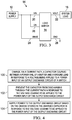
- FIG. 4 is a flow diagram of an example technique for controlling an output discharge circuit of a load switch according to this disclosure.
- load switch 14 charges (via a current path) capacitor 50 coupled between a power rail of a buffer and a ground lead.
- load switch 14 In response to voltage ceasing to be applied to the power input of the output discharge circuit, load switch 14: (a) at 102, prevents capacitor 50 from discharging through the current path; and (b) at 104, supplies power to the output discharge circuit based on the charge stored in the charged capacitor.
- an integrated circuit (e.g., load switch 14) includes: an input voltage lead (e.g., 62); an output voltage lead (e.g., 64); a pass transistor (e.g., 30) coupled between the input voltage lead and the output voltage lead; and an output discharge circuit (e.g., 42, 44, 48, 50, 54, 56).
- the output discharge circuit includes a power input (e.g., anode of one of diodes 54 and 56, such as VIBAS and VIN), a control input (e.g., gate electrode of transistor 42); a first transistor (e.g., 44) coupled between the output voltage lead and a ground lead.
- the first transistor has a control electrode.
- the output discharge circuit further includes a diode (e.g., 54 or 56) having an anode coupled to the power input; a capacitor (e.g., 50) coupled between a cathode of the diode and the ground lead; a resistor (e.g., 48) coupled between the cathode of the diode and the control electrode of the first transistor (e.g., 44); and a second transistor (e.g., 42) coupled between the control electrode of the first transistor (e.g., 44) and the ground lead.
- the second transistor (e.g., 42) has a control electrode coupled to the control input of the output discharge circuit.
- the integrated circuit further includes a switch enable lead (e.g., 68) and a control circuit (e.g., 38, 40, 46, 52, 58, 60).
- the control circuit includes a power input (e.g., anode of one of diodes 58 and 60, such as VIBAS and VIN), and a third transistor (e.g., 40) coupled between a gate electrode of the pass transistor and the control input (e.g., gate electrode of transistor 42) of the output discharge circuit.
- the third transistor has a control electrode.
- the control circuit further includes a fourth transistor (e.g., 38) coupled between the control input (e.g., gate electrode of transistor 42) of the output discharge circuit and the ground lead; and a buffer (e.g., 46) having an input coupled to the switch enable lead, an output coupled to a control electrode of the fourth transistor (e.g., 38), and a power rail coupled to the control electrode of the third transistor (e.g., 40).
- a fourth transistor e.g., 38
- a buffer e.g., 46
- the control circuit further includes a second capacitor (e.g., 52) coupled between the control electrode of the third transistor (e.g., 40) and the ground lead; and a second diode (e.g., 58 or 60) having an anode coupled to the power input of the control circuit, and a cathode coupled to the control electrode of the third transistor and to the power rail (e.g., conductor 78) of the buffer (e.g., 46).
- a second capacitor e.g., 52
- a second diode e.g., 58 or 60
- This disclosure describes an integrated circuit (e.g., load switch 14) that includes an input voltage lead (e.g., 62); an output voltage lead (e.g., 64); a pass transistor (e.g., 30) coupled between the input voltage lead and the output voltage lead; and an output discharge circuit (e.g., 42, 44, 48, 50, 54, 56) coupled between the output voltage lead and a ground lead.
- an input voltage lead e.g., 62
- an output voltage lead e.g., 64
- a pass transistor e.g., 30
- an output discharge circuit e.g., 42, 44, 48, 50, 54, 56
- the output discharge circuit includes a power input (e.g., anode of one of diodes 54 and 56, such as VIBAS and VIN); a diode (e.g., 54 or 56) having an anode coupled to the power input; and a capacitor (e.g., 50) coupled between a cathode of the diode and the ground lead.
- a power input e.g., anode of one of diodes 54 and 56, such as VIBAS and VIN
- a diode e.g., 54 or 56
- a capacitor e.g., 50
- output discharge circuit further includes a control input (e.g., gate electrode of transistor 42); and a switch (e.g., 44) coupled between the output voltage lead and the ground lead.
- the switch has a control electrode (e.g., gate of transistor 44).
- the output discharge circuit further includes a buffer (e.g., 42 and 48) having an input (e.g., gate electrode of transistor 42) coupled to the control input of the output discharge circuit, an output (e.g., drain electrode of transistor 42) coupled to the control electrode of the switch (e.g., 44), and a power rail (e.g., 84) coupled to the cathode of the diode (e.g., 54 or 56).
- the buffer (e.g., 42 and 48) is an inverter.
- the inverter is an n-type metal-oxide semiconductor (NMOS) inverter.
- NMOS n-type metal-oxide semiconductor
- the inverter may be replaced with a non-inverting buffer.
- the integrated circuit further includes a control circuit (e.g., 38, 40, 46, 52, 58, 60) coupled between a gate electrode of the pass transistor (e.g., 12) and the control input (e.g., gate electrode of transistor 42) of the output discharge circuit.
- a control circuit e.g., 38, 40, 46, 52, 58, 60
- a gate electrode of the pass transistor e.g., 12
- the control input e.g., gate electrode of transistor 42
- control circuit includes a reference voltage input e.g., (anode of one of diodes 58 and 60, such as VIBAS and VIN); a transistor (e.g., 40) coupled between the gate electrode of the pass transistor (e.g., 12) and the control input (e.g., gate electrode of transistor 42) of the output discharge circuit.
- the transistor (e.g., 40) has a control electrode.
- the control circuit further includes a second capacitor (e.g., 52) coupled between the control electrode and the ground lead; and a second diode (e.g., 58 or 60) having an anode coupled to the reference voltage input, and a cathode coupled to the control electrode of the transistor (e.g., 40).
- the reference voltage input (e.g., anode of diode 60) is coupled to the input voltage lead (e.g., 62).
- the integrated circuit further includes a bias voltage lead (e.g., 66); and a charge pump circuit (e.g., 36) coupled to the bias voltage lead; a gate driver circuit (e.g., 34) having a power input (e.g., 74) coupled to the charge pump circuit, and an output (e.g., 76) coupled to the gate of the pass transistor (e.g., 12).
- the control circuit further includes a third diode (e.g., 58) having an anode coupled to the bias voltage lead (e.g., 66), and a cathode coupled to the control electrode of the transistor (e.g., 40).
- control circuit includes a gate electrode discharge circuit (e.g., 38) coupled between the control input (e.g., gate electrode of transistor 42) of the output discharge circuit and the ground lead.
- control input e.g., gate electrode of transistor 42
- the integrated circuit further includes a switch enable lead (e.g., 68)
- the gate electrode discharge circuit includes a transistor (e.g., 38) coupled between the control input of the output discharge circuit and the ground.
- control circuit further includes a power input (anode of one of diodes 58 and 60, such as VIBAS and VIN); a buffer (e.g., inverter 46) having an input coupled to the switch enable lead (e.g., 68), an output coupled to a control electrode of the transistor (e.g., 38), and a power rail (e.g., 78); a second capacitor (e.g., 52) coupled between the power rail of the buffer and the ground lead; and a second diode (e.g., 58 or 60) having an anode coupled to the power input of the control circuit, and a cathode coupled to the power rail of the buffer (e.g., 46).
- a power input anode of one of diodes 58 and 60, such as VIBAS and VIN
- a buffer e.g., inverter 46
- the switch enable lead e.g., 68
- an output coupled to a control electrode of the transistor (e.g.,
- the power input (e.g., anode of diode 60) of the control circuit is coupled to the input voltage lead (e.g., 62).
- the integrated circuit further includes a bias voltage lead (e.g., 66); a charge pump circuit (e.g., 36) coupled to the bias voltage lead; a gate driver circuit (e.g., 34) having a power input (e.g., 74) coupled to the charge pump circuit, and an output (e.g., 76) coupled to a gate of the pass transistor; and a third diode (e.g., 58) having an anode coupled to the bias voltage lead (e.g., 66), and a cathode coupled to the power rail of the buffer (e.g., 46).
- a bias voltage lead e.g., 66
- a charge pump circuit e.g., 36
- a gate driver circuit e.g., 34
- a third diode e.g., 58
- the output discharge circuit further includes a control input (e.g., gate electrode of transistor 42); a switch (e.g., 44) coupled between the output voltage lead and the ground lead.
- the switch has a control electrode (e.g., gate electrode of transistor 44); a resistive component (e.g., 48) coupled between the cathode of the diode (e.g., 54 or 56) and the control electrode of the switch (e.g., 44); and a transistor (e.g., 42) coupled between control electrode of the switch (e.g., 44) and the ground lead.
- the transistor (e.g., 42) has a control electrode (e.g., gate of transistor 42) coupled to the control input of the output discharge circuit.
- the power input (e.g., anode of diode 56) of the output discharge circuit is coupled to the input voltage lead (e.g., 62).
- the integrated circuit further includes a bias voltage lead (e.g., 66); a charge pump circuit (e.g., 36) coupled to the bias voltage lead; a gate driver circuit (e.g., 34) having a power input (e.g., 74) coupled to the charge pump circuit, and an output (e.g., 76) coupled to a gate of the pass transistor (e.g., 12).
- the power input (e.g., anode of diode 54) of the output discharge circuit is coupled to the bias voltage lead (e.g., 66).
- the output discharge circuit further includes a second power input (anode of one of diodes 54 and 56, such as VIBAS and VIN); a second diode (e.g., 54 or 56) having an anode coupled to the second power input.
- a cathode of the second diode is coupled to the capacitor (e.g., 50) and to the cathode of the first diode (e.g., 54 or 56).
- Load switches with quick output discharge circuits may function improperly when the part loses input power.
- some applications such as solid state drives, if the output is discharged improperly, then data corruption may occur if the downstream circuitry is shut down improperly.
- Some examples may use a large capacitor to make an internal power supply, which allows the discharge buffer to have power, even if an external power supply is removed.
- Example embodiments may allow an output discharge to continue functioning, even after an input power loss.
- example embodiments may allow load switch users to discharge the output of a load switch when relatively large capacitance loads (e.g., ⁇ 200uF) are coupled to the output of the load switch, even with a loss of power supply to the device.
- relatively large capacitance loads e.g., ⁇ 200uF
- a load switch When a load switch is disabled while power is applied, the output may be discharged, so potential issues at downstream circuitry are avoided.
- a load switch user may couple or tie the enable pin (ON pin) to the input supply, so the load switch may shut off when power drops.
- the output discharge circuit of load switch 14 may be configured to discharge a load capacitance (e.g., capacitance of system load 16) that is greater than or equal to 50 microfarads ( ⁇ F), such as greater than or equal to 100 ⁇ F or 200 ⁇ F.
- a load capacitance e.g., capacitance of system load 16
- ⁇ F microfarads
- Some examples may discharge a load capacitor tied to the VOUT pin when VIN supply is removed. Further examples may allow the output capacitance to be discharged when the load switch is disabled, and with VBIAS (e.g., power supply to the integrated circuit (IC)) and VIN (e.g., voltage to pass transistor) dropping out. Additional examples may keep VOUT pulled low (e.g., to ground) when VIN is available yet VBIAS is absent, which may serve as a safety function and/or to avoid data corruption.
- VBIAS power supply to the integrated circuit
- VIN e.g., voltage to pass transistor
- example embodiments may provide some or all of the above-mentioned functionality with low quiescent current. They may ensure that the pass power FET (e.g., transistor 30) is fully off when either VBIAS or VIN exist, before the output discharge circuit is engaged to prevent shoot-through current.
- a load switch may include a circuit to power the gate pull down of the power FET on loss of either VIN or VBIAS.
- a load switch may include a circuit to hold voltage for an inverter or buffer power supply in the event of VIN or VBIAS loss.
- Example embodiments may allow an output discharge circuit to discharge a large capacitive load with input power disappearing suddenly.
- an output discharge circuit designed in accordance with this disclosure may be able to discharge a voltage on a 100 ⁇ F capacitor to near zero in less than 10 milliseconds (ms), such as less than approximately 2 ms.
- one or more of diodes 54, 56, 58, 60 may be implemented using parasitic diodes formed by p-n junctions in one or more MOS transistors (e.g., NMOS transistors).
- MOS transistors e.g., NMOS transistors
- inverter 46 may be replaced by a common source transistor stage that is either actively loaded (e.g., with a transistor) or passively loaded (e.g., with a resistor).
- transistor 42 and resistor 48 may form a passively-loaded common source stage.
- the techniques and circuitry described in this disclosure may be implemented on any combination of one or more integrated circuits or other devices.
Description
- The disclosure relates generally to electrical circuits, and more particularly to load switches.
- Load switches may be used in a variety of electronic devices, such as personal electronics (e.g., solid state drives and tablets), electronic point of sale devices (e.g., bar code scanners and payment terminals), industrial personal computers, home appliances, and servers. Load switches may be used for power distribution, power sequencing, reducing leakage current, controlling inrush current, and controlling power downs.
- Load switches may act as electronic relays that turn on and off power rails that are used for powering downstream components in electronic devices. When a load switch is turned off, charge may continue to reside on the output of the load switch, which may disturb the downstream electronic components. Significant design challenges exist in dealing with the residual charge on the output of the load switch, especially in cases where power supply to the load switch is turned off.
US 2009/315595 relates to an output drive circuit.DE 36 39 495 - An integrated circuit and a corresponding method are defined in the appended independent claims 1 and 15. Preferred features are defined in the dependent claims.
-
-
FIG. 1 is a block diagram of an example system that includes a load switch according to this disclosure. -
FIG. 2 is a schematic showing additional details of an example load switch according to this disclosure. -
FIG. 3 is a block diagram of another example system that includes a load switch according to this disclosure. -
FIG. 4 is a flow diagram of an example technique for controlling an output discharge circuit of a load switch according to this disclosure. - This disclosure describes output discharge techniques for discharging the output of a load switch. Load switches may use an output discharge circuit to discharge the output of the load switch when the switch is turned off. The output discharge circuit may be a powered circuit that is powered by one or more power supplies coupled to the load switch. If the power supply to the load switch is turned off while (or soon after) the load switch turns off, then it may interfere with operation of the output discharge circuit, thereby preventing the output of the switch from being discharged.
- According to this disclosure, an output discharge circuit for a load switch may include a capacitor coupled between a power rail of the output discharge circuit and a ground lead, and a diode coupled between a power input of the output discharge circuit and the power rail. The output discharge circuit may charge the capacitor via a current path formed by the diode while power is being supplied to the load switch. When the power supply to the output discharge circuit is turned off, the diode may prevent the capacitor from discharging through the current path, and the stored charge on the capacitor may be used for powering the output discharge switch during a period of time after the power supply has been turned off. In this way, the output discharge circuit may continue to discharge the output of the load switch, even when power ceases being supplied to the load switch.
- In some examples, the output discharge circuit may include a discharge switch that is coupled between the output of the load switch and a ground rail. The output discharge circuit may further include a buffer (e.g., an inverter) that is coupled to a control input of the discharge switch. The buffer may control the discharge switch based on an input control signal, and may be powered by a power supply input. A high logic voltage may be needed to close the discharge switch in order to discharge the load switch. For example, the discharge switch may be an n-type metal-oxide-semiconductor (NMOS) transistor, and a voltage greater than the turn-on threshold voltage of the NMOS transistor may be needed to turn the transistor on. If the buffer does not receive sufficient power, then the buffer may be unable to produce a voltage sufficient to turn the NMOS transistor on, which may prevent the output of the load switch form discharging.
- According to this disclosure, a capacitor may be coupled between a power rail of the buffer and a ground rail, and a diode may be coupled between a power input of the output discharge circuit and the power rail of the buffer. The capacitor and diode may allow the buffer to supply a high logic voltage for a time period after power has been removed from the power input of the output discharge circuit. In this way, a buffer-based (or inverter-based) output discharge circuit may be able to continue discharging the output of a load switch, even without an active power supply.
- A buffer-based (e.g., inverter-based) output discharge circuit may allow an active-low output discharge control signal to be used for controlling an active-high discharge switch. An active-low output discharge control signal may refer to a control signal that causes the discharge switch to close and discharge the load switch output when the voltage is below a threshold, and to open when the voltage is above the threshold. An active-high discharge switch may be a switch that closes when the voltage is above a threshold and opens when the voltage is below a threshold.
- In some examples, the buffer may be an inverter, such as an NMOS inverter with a resistive load or an active load. An NMOS inverter may be able to level shift the input voltage to a higher voltage.
- A buffer-based output discharge circuit that uses an active-low output discharge control signal may also allow the output discharge circuit to be controlled (at least partially) by the pass transistor gate voltage of the load switch. By using the gate voltage of the pass transistor as a control signal, the activation of the output discharge circuit may be deferred until the pass transistor's gate has reached a low voltage sufficient to ensure that the pass transistor is turned off, thereby preventing excessive current in-rush that would otherwise occur if the pass transistor were turned on.
- When the pass transistor of a load switch is turned on, the gate voltage of the pass transistor may be high enough to damage other components in the output discharge circuit and/or associated control circuitry. In examples where the gate voltage is used for deferring the turning on of the output discharge switch, a gate voltage coupling circuit may be used for: decoupling the gate voltage of the pass transistor from the control input of the output discharge circuit when the gate voltage is above a threshold voltage; and coupling the gate voltage to the control input when the gate voltage is below a threshold voltage. In this way, the gate voltage may be used for controlling when the output discharge circuit turns on, while avoiding damage that may be caused by excessively high gate voltages being directly applied to the control input of the output discharge switch.
- In some examples, the gate voltage coupling circuit may include a transistor coupled between the gate voltage of the pass transistor and the control input of the output discharge circuit. In such examples, the control electrode of the transistor may be coupled to a reference voltage, which may define or control a threshold voltage for the gate voltage coupling circuit. When the pass transistor gate voltage is below the threshold voltage, the gate voltage coupling circuit transistor may output the pass transistor gate voltage to the control input of the output discharge circuit. By comparison, when the pass transistor gate voltage is above the threshold voltage, the gate voltage coupling circuit transistor may output the threshold voltage to the control input of the output discharge circuit. In this way, the output of the gate voltage coupling circuit may be limited to a relatively low voltage that does not damage other control circuitry in the load switch.
- The reference voltage for the gate voltage coupling circuit transistor may be supplied by a power supply. However, if the power supply is turned off, then the gate voltage coupling circuit transistor may output a low voltage that causes the output discharge circuit to activate, even if the gate voltage of the pass transistor is still high enough to turn the pass transistor on. If the output discharge circuit is activated while the pass transistor is still turned on, then it may cause undesirable levels of inrush current.
- According to this disclosure, a capacitor may be coupled between a control electrode of the gate voltage coupling circuit transistor and a ground rail, and a diode may be coupled between a reference voltage input and the control electrode of the gate voltage coupling circuit transistor. The capacitor and diode may allow the gate voltage coupling circuit transistor to continue operating, even after power has ceased being supplied to the reference voltage input. In this way, the activation of an output discharge circuit may be delayed until after the pass transistor of the load switch turns off, even when power ceases being supplied to the gate voltage coupling circuit.
- In some examples, control circuitry for the output discharge circuit may also include a pass transistor gate discharge circuit that forms a discharge path for the gate voltage of the pass transistor when the pass transistor is turned off. Such a circuit may include a transistor that is coupled between the control input of the output discharge circuit and a ground rail. This transistor may form a pass transistor discharge path in conjunction with the gate voltage coupling circuit.
- The pass transistor gate discharge circuit may further include a buffer (e.g., an inverter) with an output that is coupled to a control electrode of the transistor. The buffer may be controlled by an enable input of the load switch, and may be powered by a power supply received from the power input. If the power supply is turned off, then the buffer may output a low logic voltage, which may prevent the gate discharge circuit from forming a discharge path for the pass transistor, thereby preventing the pass transistor from turning off when the load switch is disabled.
- According to this disclosure, a capacitor may be coupled between a power rail of the buffer and a ground rail, and a diode may be coupled between a power input of the load switch and the power rail of the buffer. The capacitor and diode may allow the buffer to continue supplying a high logic voltage to the gate discharge circuit transistor, even after power has ceased being supplied to the load switch. In this way, the pass transistor's gate may continue being discharged, even when power ceases being supplied to the load switch.
- In additional examples, instead of using a single diode for connecting a power supply to a power rail or to a control electrode, multiple diodes may be used for connecting multiple different power supplies to the power rails or control electrodes. In this way, even if one power supply is turned off, another of the power supplies may continue to supply power to the control circuitry, thereby providing an output discharge circuit that is more robust to losses of power in a single power supply.
-
FIG. 1 is a block diagram of anexample system 10, which includes apower supply 12, aload switch 14, asystem load 16, aswitch control circuit 18, and leads 20, 22, 24, 26, 28. - A power output of
system 10 is coupled to a voltage input (VIN) ofload switch 14 vialead 20 and to a bias voltage input (VBIAS) ofload switch 14 vialead 24. An output ofswitch control circuit 18 is connected to an enable input (ON) ofload switch 14 vialead 26. A voltage output (VOUT) ofload switch 14 is coupled to system load 16 vialead 22. A ground input (GND) ofload switch 14 is coupled to a ground terminal vialead 28. - In some examples, system load 16 may include one or more powered electronic components. In one example, the powered electronic components may be one or more solid-state drive components. In further examples, system load 16 may include one or more capacitors.
- During operation,
power supply 12 supplies power to the voltage input and the bias voltage input vialead 24.Switch control circuit 18 enables and disables load switch 14 (e.g., turnsload switch 14 on and off) by sending one or more control signals to the enable input ofload switch 14 vialead 26. When load switch 14 is turned on,load switch 14 may turn on a pass transistor coupled between VIN and VOUT, so a current path is formed between VIN and VOUT. The current path formed byload switch 14 may allow power (e.g., voltage and/or current) to pass throughload switch 14 to one or more power rails insystem load 16, thereby charginglead 22 and one or more power rails insystem load 16. When load switch 14 is turned off,load switch 14 may turn the pass transistor off, so an open circuit is formed between VIN and VOUT. The open circuit formed byload switch 14 may prevent power from being transferred throughload switch 14 to one or more power rails insystem load 16. - To turn
load switch 14 off,switch control circuit 18 may transition a control signal carried bylead 26 from a first logic state to a second logic state (e.g., transition the control signal from a high logic state to a low logic state). In response to the transition,load switch 14 may turn off the pass transistor coupled between VIN and VOUT. However, some residual charge may still remain onlead 22 and the power rails insystem load 16. -
Load switch 14 may include an output discharge circuit that is configured to discharge VOUT when load switch 14 is turned off. The output discharge circuit may be a powered circuit that is powered by one or more power sources. In theexample system 10 ofFIG. 1 , the output discharge switch is powered bypower supply 12. For example, a power input of the output discharge switch may be coupled to one or both of VIN or VBIAS. Ifpower supply 12 is turned off during (or soon after)load switch 14 turns off, then it may interfere with operation of the output discharge circuit, thereby preventing the output of load switch 14 from being discharged. -
Load switch 14 may include a capacitor coupled between a power rail of the output discharge circuit and a ground lead, and a diode coupled between a power input of the output discharge circuit and the power rail. The output discharge circuit may charge the capacitor via a current path formed by the diode whenpower supply 12 is supplying power to loadswitch 14. Whenpower supply 12 ceases to supply power to loadswitch 14, the diode may prevent the capacitor from discharging through the current path formed by the diode, and the stored charge on the capacitor may be used for powering the output discharge switch during a period of time afterload switch 14 ceases to supply power. In this way,load switch 14 may continue to discharge VOUT, even when power ceases being supplied to loadswitch 14. - In some examples, the output discharge circuit in
load switch 14 may be controlled at least partially based on the gate voltage of the pass transistor inload switch 14. This may allow the activation of output discharge circuit to be delayed until after the pass transistor is turned off. When coupling the gate voltage to the control circuitry for the output discharge circuit, a gate voltage coupling circuit may be used for preventing high voltages on the pass transistor's gate from damaging the control circuit. The gate voltage coupling circuit may operate based on a reference voltage that is supplied bypower supply 12 via one or both of VIN and VBIAS. However, if thepower supply 12 is turned off, then the gate voltage coupling circuit may cause the output discharge circuit to activate, even if the pass transistor is still turned on, which may in turn cause undesirable levels of inrush current. - A capacitor may be coupled between a control electrode of the gate voltage coupling circuit and a ground rail. A diode may be coupled between a reference voltage input and the control electrode of the gate voltage coupling circuit. The capacitor and diode may allow the gate voltage coupling circuit to continue operating, even after power has ceased being supplied to the reference voltage input of the gate voltage coupling circuit. In this way, the activation of an output discharge circuit may be delayed until after the pass transistor of
load switch 14 turns off, even when power ceases being supplied to loadswitch 14. - In additional examples, the control circuitry for the output discharge circuit of
load switch 14 may also include a pass transistor gate discharge circuit that forms a discharge path for the gate voltage of the pass transistor when the pass transistor is turned off. Such a circuit may include a buffer (e.g., inverter) that is controlled by an enable input (ON) ofload switch 14 and that is powered bypower supply 12 via one or both of VIN and VBIAS. Ifpower supply 12 is turned off, then the buffer may output a low voltage, which may prevent the gate discharge circuit from forming a discharge path for the pass transistor, which may prevent the pass transistor from turning off when the load switch is disabled. - A capacitor may be coupled between a power rail of the buffer and a ground rail, and a diode may be coupled between a power input of the load switch and the power rail of the buffer. The capacitor and diode may allow the buffer to continue supplying a high voltage to the gate discharge circuit transistor, even after power has ceased being supplied to the load switch. In this way, the pass transistor's gate may continue being discharged, even when power ceases being supplied to load
switch 14. -
FIG. 2 is a schematic showing additional details ofexample load switch 14.Load switch 14 includes apass transistor 30, agate control circuit 32, agate driver 34, acharge pump 36,transistors inverter 46, aresistor 48,capacitors diodes input voltage lead 62, anoutput voltage lead 64, abias voltage lead 66, a switch enablelead 68, aground lead 70, andconductors Conductors load switch 14. - In some examples, all or a portion of
load switch 14 may be formed on one or more integrated circuits. In such examples, one or more ofinput voltage lead 62,output voltage lead 64,bias voltage lead 66, switch enablelead 68, andground lead 70 may be coupled to respective input or output pins of the integrated circuit. - A drain electrode of
pass transistor 30 is coupled to inputvoltage lead 62. A source electrode ofpass transistor 30 is coupled tooutput voltage lead 64. A control input ofgate control circuit 32 is coupled to switch enablelead 68. An output ofgate control circuit 32 is coupled to aninput gate driver 34 viaconductor 72. An output ofgate driver 34 is coupled to a gate electrode ofpass transistor 30 viaconductor 76. A reference voltage input ofcharge pump 36 is coupled tobias voltage lead 66. An output ofcharge pump 36 is coupled to a first power input ofgate driver 34 viaconductor 74. A second power input ofgate driver 34 is coupled toground lead 70. - A drain electrode of
transistor 44 is coupled to a source electrode ofpass transistor 30 and tooutput voltage lead 64. A source electrode oftransistor 44 is coupled toground lead 70. A drain electrode oftransistor 42 is coupled to a gate electrode oftransistor 44 viaconductor 86. A source electrode oftransistor 42 is coupled toground lead 70. - An anode of
diode 54 is coupled tobias voltage lead 66. An anode ofdiode 56 is coupled to inputvoltage lead 62. The cathodes ofdiodes resistor 48 andcapacitor 50 via conductor 84. A second terminal ofcapacitor 50 is coupled toground lead 70. A second terminal ofresistor 48 is coupled to the drain electrode oftransistor 42. - A drain electrode of
transistor 40 is coupled to a gate electrode ofpass transistor 30 viaconductor 76. A source electrode oftransistor 40 is coupled to the gate electrode oftransistor 42 viaconductor 82. - An anode of
diode 58 is coupled tobias voltage lead 66. An anode ofdiode 60 is coupled to inputvoltage lead 62. The cathodes ofdiodes capacitor 52, to a gate electrode oftransistor 40, and to a power input ofinverter 46 viaconductor 78. A second terminal ofcapacitor 52 is coupled toground lead 70. - A drain electrode of
transistor 38 is coupled to the source electrode oftransistor 40 and to the gate electrode oftransistor 42 viaconductor 82. A source electrode oftransistor 38 is coupled toground lead 70. - An input of
inverter 46 is coupled to switch enablelead 68. An output ofinverter 46 is coupled to the gate electrode oftransistor 38 viaconductor 80. A power input ofinverter 46 is coupled to the cathodes ofdiodes capacitor 52 viaconductor 78. - As shown in
FIG. 2 , each oftransistors pass transistor 30 andtransistor 40 may be high voltage transistors, andtransistors transistor 40 may be a drain extended n-type MOS (DENMOS) transistor. - Although the
example load switch 14 ofFIG. 2 is described with respect to NMOS transistors, any combination of the same or different types of transistors may be used with the same or different conductivity types.Transistors transistors - In some examples, one or both of
capacitors load switch 14. For example,capacitor 50 may be greater than or equal to 10 picofrarads (pF), such as greater than or equal to 15 pF or 20 pF. -
Gate control circuit 32 may control the operation ofpass transistor 30 in response to an enable signal carried by switch enablelead 68. For example,gate control circuit 32 may produce one or more signals onconductor 72 that causegate driver 34 to either produce or not produce a voltage sufficient to turnpass transistor 30 on.Gate driver 34 may provide a voltage sufficient to turnpass transistor 30 on, in response to receiving an appropriate control signal viaconductor 72. -
Charge pump 36 may generate a voltage sufficient to turnpass transistor 30 on, based on a voltage carried bybias voltage lead 66.Gate driver 34 may use the voltage generated bycharge pump 36 to provide a voltage to the gate ofpass transistor 30 that is sufficient to turnpass transistor 30 on (e.g., the voltage may be greater than the source voltage ofpass transistor 30 added to the turn-on threshold voltage of pass transistor 30). In some examples, the voltage carried bybias voltage lead 66 may be insufficient to turnpass transistor 30 on (e.g., the voltage may be less than the source voltage ofpass transistor 30 added to the turn-on threshold voltage of pass transistor 30). -
Transistor 44 may form an output discharge switch that is coupled betweenoutput voltage lead 64 andground lead 70. When a high voltage signal is applied to the control electrode oftransistor 44, the output discharge switch may close, thereby forming a current conduction path betweenoutput voltage lead 64 andground lead 70. When a low voltage signal (e.g., zero volts) is applied to the control electrode oftransistor 44, the output discharge switch may open, thereby disconnecting output voltage lead 64 fromground lead 70. -
Transistor 42 andresistor 48 may form an NMOS inverter, or more generally an inverter, and even more generally a buffer (e.g., an inverting buffer). The gate electrode oftransistor 42 may form an input of the buffer, and the drain electrode oftransistor 42 may form an output of the buffer. Conductor 84 may form a power rail for the buffer. - When a low voltage signal is received at the control electrode of
transistor 42, the buffer may output a high voltage signal. For example,transistor 42 may turn off, which may cause the output voltage (i.e., the voltage at the drain of transistor 42) to be substantially equal to the voltage carried by the power rail formed by conductor 84. The voltage carried by the power rail formed by conductor 84 may be approximately equal to one or both of the voltages carried byinput voltage lead 62 andbias voltage lead 66, which may correspond to high logic voltage. - When a high voltage signal is received at the control electrode of
transistor 42, the buffer may output a low voltage signal. For example,transistor 42 may turn on, which may form a voltage drop acrossresistor 48, thereby causing a low voltage to be carried byconductor 86. The low voltage may correspond to a low logic voltage. - The inverter (formed by
transistor 42 and resistor 48) and the output discharge switch (formed by transistor 44) may together form an output discharge circuit that is coupled betweenoutput voltage lead 64 andground lead 70. The output discharge circuit has an input formed by the control electrode oftransistor 42. -
Transistor 40 may form a gate voltage coupling circuit that is coupled between the gate ofpass transistor 30 and the input of the output discharge circuit that is formed by the control electrode oftransistor 42. The control electrode oftransistor 40 may receive a reference voltage carried byconductor 78, which may be approximately equal to one or both of the voltages carried byinput voltage lead 62 andbias voltage lead 66. The reference voltage may determine whethertransistor 40 operates in a triode mode or in a saturation mode. Whentransistor 40 is operating in the triode mode,transistor 40 may output a voltage at the source electrode oftransistor 40 that is approximately equal to the pass transistor gate voltage carried byconductor 76. Whentransistor 40 is operating in the saturation mode,transistor 40 may output a voltage that is less than the voltage at the gate electrode oftransistor 40, regardless of the pass transistor gate voltage's magnitude. -
Transistor 38 may form a gate voltage discharge switch that is coupled between the input of the output discharge circuit (formed bytransistors ground lead 70. When a high voltage signal is applied to the control electrode oftransistor 38, the gate voltage discharge switch may close, thereby forming a current conduction path between the gate ofpass transistor 30 andground lead 70. Specifically, the current conduction path (or discharge path) may be formed through both oftransistors transistor 38, the gate voltage discharge switch may open, thereby disconnecting the gate ofpass transistor 30 fromground lead 70. - The gate voltage discharge switch formed by
transistor 38 may be controlled by the voltage carried by the output ofinverter 46, which in turn may be controlled by the voltage carried by switch enablelead 68. In response to switch enablelead 68 carrying a low voltage,inverter 46 may output a high voltage, thereby turning ontransistor 38 and forming a gate voltage discharge path. In response to switch enablelead 68 carrying a high voltage,inverter 46 may output a low voltage, thereby turning offtransistor 38 and disconnecting the gate ofpass transistor 30 fromground lead 70.Conductor 78 may form a power rail forinverter 46. The voltage carried by the power rail formed byconductor 78 may be approximately equal to one or both of the voltages carried byinput voltage lead 62 andbias voltage lead 66. -
Transistors inverter 46 may form a control circuit that controls the output discharge circuit formed bytransistors resistor 48. The control circuit may control the output discharge circuit at least partially based on the gate voltage ofpass transistor 30, and may also discharge the gate voltage ofpass transistor 30 by forming a gate voltage discharge path in response to loadswitch 14 being disabled (i.e., in response to the voltage carried by switch enable lead transitioning to a low logic voltage). - When voltages are applied to one or both of
bias voltage lead 66 andinput voltage lead 62,diodes bias voltage lead 66 andinput voltage lead 62, thereby allowingcapacitor 50 to be charged.Diodes capacitor 50 from being discharged (throughdiodes 54 and 56) when voltages cease being applied tobias voltage lead 66 andinput voltage lead 62 respectively. - Similarly, when voltages are applied to one or both of
bias voltage lead 66 andinput voltage lead 62,diodes bias voltage lead 66 andinput voltage lead 62, thereby allowingcapacitor 52 to be charged.Diodes capacitor 52 from being discharged (throughdiodes 58 and 60) when voltages cease being applied tobias voltage lead 66 andinput voltage lead 62 respectively. - In at least one example operation,
load switch 14 is enabled, and power is supplied to bothinput voltage lead 62 andbias voltage lead 66. To enableload switch 14, a switch control circuit (e.g.,switch control circuit 18 inFIG. 1 ) asserts a high logic voltage on switch enablelead 68. In response to receiving the high logic voltage,gate control circuit 32 outputs a signal viaconductor 72 that causesgate driver 34 to turnpass transistor 30 on.Charge pump 36 generates a voltage based on the voltage carried bybias voltage lead 66 that is sufficient to turnpass transistor 30 on, and outputs the voltage to the power input ofgate driver 34. In response to receiving the signal fromgate control circuit 32 viaconductor 72,gate driver 34 generates a voltage sufficient to turnpass transistor 30 on.Pass transistor 30 turns on, thereby forming a current conduction path betweeninput voltage lead 62 andoutput voltage lead 64. -
Inverter 46 is powered by one or both ofinput voltage lead 62 andbias voltage lead 66. In response to receiving the high logic voltage carried by switch enablelead 68,inverter 46 outputs a low logic voltage to the gate electrode oftransistor 38, which turnstransistor 38 off. Consequently, the gate electrode ofpass transistor 30 is disconnected from ground lead 70 (i.e., no current path is formed between the gate electrode ofpass transistor 30 and ground lead 70). The voltages supplied byinput voltage lead 62 andbias voltage lead 66 may be less than the voltage at the gate electrode ofpass transistor 30 whenpass transistor 30 is turned on. Thus,transistor 40 may operate in saturation andcharge conductor 82, until the voltage atconductor 82 reaches a voltage sufficient tocutoff transistor 40.Transistor 40 may chargeconductor 82 to a voltage level that is approximately equal to the voltage at the gate electrode oftransistor 40, less the gate turn-on threshold voltage oftransistor 40. This voltage may be sufficient to turntransistor 42 on. - The inverter formed by
transistor 42 andresistor 48 is powered by one or both ofinput voltage lead 62 andbias voltage lead 66. In response to the relatively high voltage provided bytransistor 40,transistor 42 turns on and forms a current path betweenresistor 48 andground lead 70. This causes: a voltage drop acrossresistor 48; and a low logic voltage to be produced at the gate electrode oftransistor 44. In response to receiving the low logic voltage at the gate electrode,transistor 44 remains turned off, thereby preventing the formation of a discharge path fromoutput voltage lead 64 toground lead 70. - During normal operation, when load switch 14 is enabled,
diodes capacitor 50 to be charged to a voltage level approximately equal to one or both ofinput voltage lead 62 andbias voltage lead 66. Similarly,diodes capacitor 52 to be charged to a voltage level approximately equal to one or both ofinput voltage lead 62 andbias voltage lead 66. - In at least one other example operation,
load switch 14 is disabled, and power continues to be supplied to bothinput voltage lead 62 andbias voltage lead 66. To disableload switch 14, a switch control circuit (e.g.,switch control circuit 18 inFIG. 1 ) asserts a low logic voltage on switch enablelead 68. In response to receiving the low logic voltage,gate control circuit 32 outputs a signal viaconductor 72 that causesgate driver 34 to cease generating a voltage sufficient to turnpass transistor 30 on. Initially,pass transistor 30 may remain turned on until: a discharge path is formed thoughtransistors pass transistor 30 is sufficiently discharged to turnpass transistor 30 off. -
Inverter 46 is powered by one or both ofinput voltage lead 62 andbias voltage lead 66. In response to receiving the low logic voltage carried by switch enablelead 68,inverter 62 outputs a high logic voltage to the gate electrode oftransistor 38, which turnstransistor 38 on. Consequently, a current conduction path (e.g., a discharge path) is formed between the gate electrode ofpass transistor 30 andground lead 70. Initially, the voltages supplied byinput voltage lead 62 andbias voltage lead 66 may be less than the voltage at the gate electrode ofpass transistor 30 when load switch 34 is first disabled. Thus,transistor 40 may initially operate in the saturation mode andcharge conductor 82 to a voltage that is less than the voltage at the gate oftransistor 40, but still sufficient to keeptransistor 42 turned on. - As the gate electrode of
pass transistor 30 continues to discharge, the gate voltage ofpass transistor 30 may become less than the voltage at the gate oftransistor 40 by an amount sufficient to cause a transitioning oftransistor 40 away from operating in the saturation mode to instead operate in the triode mode. In response to operating in the triode mode,transistor 40 may chargeconductor 82 to a voltage level that is approximately is equal to the voltage at the gate electrode ofpass transistor 30, thereby effectively coupling the source electrode oftransistor 40 to the gate electrode ofpass transistor 30. - During the discharge of the gate electrode of
pass transistor 30,pass transistor 30 turns off, thereby disconnectinginput voltage lead 62 fromoutput voltage lead 64. As the gate electrode ofpass transistor 30 continues to further discharge, the gate voltage ofpass transistor 30 may become less than a voltage required to keeptransistor 42 turned on, thereby causingtransistor 42 to turn off. In response totransistor 42 turning off, the drain oftransistor 42 may charge up to a voltage approximately equal to the voltage of one or both ofbias voltage lead 66 andinput voltage lead 62. This voltage is sufficient to turntransistor 44 on, thereby forming a current conduction path (e.g., a discharge path) betweenoutput voltage lead 64 andground lead 70. The charge stored onoutput voltage lead 64 is discharged through the current conduction path formed byground lead 70. - As discussed above, the activation of the output discharge circuit (e.g., the turning of
transistor 44 on) depends on the inverter formed bytransistor 42 andresistor 48 raising the voltage at the gate oftransistor 44 to a sufficiently high voltage for turningtransistor 44 on. If sufficient power is not provided to the power rail (e.g., conductor 84) of the inverter formed bytransistor 42 andresistor 48, the inverter may be unable to produce a sufficiently high voltage to keeptransistor 44 turned on, thereby preventing the output of load switch 14 from being discharged. -
Load switch 14 may includecapacitor 50 coupled between a power rail (e.g., conductor 84) of the output discharge circuit andground lead 70, anddiodes capacitor 50 via current paths formed bydiodes input voltage lead 62 and/or bias voltage lead 66). When the power supply ceases supplying power to inputvoltage lead 62 andbias voltage lead 66,diodes capacitor 50 from discharging through the current paths, and the stored charge oncapacitor 50 may be used for powering the output discharge switch during a period of time after the power supply ceases to supply power. In this way,load switch 14 may continue to discharge VOUT, even when power ceases being supplied to loadswitch 14. - The output discharge circuit in
FIG. 2 may be controlled at least partially based on the gate voltage ofpass transistor 30. This may allow the activation of output discharge circuit to be delayed untilpass transistor 30 is turned off. When coupling the gate voltage ofpass transistor 30 to the control circuitry for the output discharge circuit, a gate voltage coupling circuit (e.g., transistor 40) may be used for preventing high voltages on the pass transistor's gate from damaging the control circuit.Transistor 40 may operate based on a reference voltage that is supplied by one or both ofinput voltage lead 62 andbias voltage lead 66. If the reference voltage is not supplied totransistor 40, thentransistor 40 may cause the output discharge circuit to activate, even ifpass transistor 30 is still turned on, which may cause undesirable levels of inrush current. -
Capacitor 52 may be coupled between a control electrode oftransistor 40 andground lead 70.Diodes input voltage lead 62 and bias voltage lead 66) and the control electrode oftransistor 40. The control circuit may chargecapacitor 52 via current paths formed bydiodes input voltage lead 62 and/or bias voltage lead 66). When the power supply ceases supplying power to inputvoltage lead 62 andbias voltage lead 66,diodes capacitor 52 from discharging through the current paths, and the stored charge oncapacitor 52 may be used for providing a reference voltage totransistor 40 during a period of time after the power supply ceases to supply power, thereby allowingtransistor 40 to continue operating, even after power ceases being supplied to the reference voltage inputs. In this way, the activation of an output discharge circuit may be delayed until afterpass transistor 30 turns off, even when power ceases being supplied to loadswitch 14. - In additional examples, the control circuitry for the output discharge circuit of
load switch 14 may also include a pass transistor gate discharge circuit (e.g., transistor 38) that forms a discharge path for the gate voltage ofpass transistor 30 when load switch 14 is turned off. Such a circuit may include a buffer (e.g., inverter 46) that is controlled by an enable input ofload switch 14 and is powered by one or both ofbias voltage lead 66 andinput voltage lead 62 ofload switch 14. If power ceases being supplied toinverter 46, then inverter 46 may output a low voltage, which may prevent the gate discharge circuit from forming a discharge path for the gate ofpass transistor 30, and which may prevent or delaypass transistor 30 from turning off when disabled. -
Capacitor 52 may be coupled between a power rail (e.g., conductor 78) ofinverter 46 andground lead 70, anddiodes load switch 14 and the power rail ofinverter 46.Capacitor 52 anddiodes inverter 46 to continue supplying a high voltage totransistor 38, even after power has ceased being supplied to loadswitch 14. In this way, the gate ofpass transistor 30 may continue being discharged, even when power ceases being supplied to loadswitch 14. - The
example load switch 14 ofFIG. 2 includes twodiodes diode 54 andbias voltage lead 66 may be removed, leaving a single power input (e.g., input voltage lead 62) and a single diode (e.g., diode 56). As another example,input voltage lead 62 anddiode 56 may be removed, leaving a single power input (e.g., diode 54) and a single diode (e.g., bias voltage lead 66). - Similarly, more or fewer power inputs and diodes may be used for
diodes diode 58 andbias voltage lead 66 may be removed, leaving a single power input (e.g., input voltage lead 62) and a single diode (e.g., diode 60). As another example,input voltage lead 62 anddiode 60 may be removed, leaving a single power input (e.g., diode 58) and a single diode (e.g., bias voltage lead 66). -
FIG. 3 is a block diagram of anotherexample system 90 that includesexample load switch 14.System 90 is similar tosystem 10 ofFIG. 1 , except: (a)switch control circuit 18 is omitted; and (b)lead 26 is coupled topower supply 12 vialead 20. A load switch user may couple or tie the enable pin (ON pin) to VIN, so loadswitch 14 may turn off whenpower supply 12 is turned off. - To disable
load switch 14,power supply 12 may be turned off. However, ifpower supply 12 is turned off, then it may also turn off the power supply to inputvoltage lead 62 andbias voltage lead 66 ofFIG. 2 . Nevertheless, theload switch 14 ofFIG. 2 may still allow the switch to smoothly turn off and the output discharge circuit to seamlessly discharge VOUT, even when power ceases being supplied to VIN and VBIAS. Accordingly, the techniques of this disclosure become especially useful in systems where designers may want to couple together the enable pin (ON) ofload switch 14 to one or both of VIN and VBIAS. -
FIG. 4 is a flow diagram of an example technique for controlling an output discharge circuit of a load switch according to this disclosure. At 100, in response to a voltage being applied to a power input of an output discharge circuit of a switch, load switch 14 charges (via a current path)capacitor 50 coupled between a power rail of a buffer and a ground lead. In response to voltage ceasing to be applied to the power input of the output discharge circuit, load switch 14: (a) at 102, preventscapacitor 50 from discharging through the current path; and (b) at 104, supplies power to the output discharge circuit based on the charge stored in the charged capacitor. - Referring again to
FIG. 2 , an integrated circuit (e.g., load switch 14) includes: an input voltage lead (e.g., 62); an output voltage lead (e.g., 64); a pass transistor (e.g., 30) coupled between the input voltage lead and the output voltage lead; and an output discharge circuit (e.g., 42, 44, 48, 50, 54, 56). The output discharge circuit includes a power input (e.g., anode of one ofdiodes - In some examples, the integrated circuit further includes a switch enable lead (e.g., 68) and a control circuit (e.g., 38, 40, 46, 52, 58, 60). The control circuit includes a power input (e.g., anode of one of
diodes - This disclosure describes an integrated circuit (e.g., load switch 14) that includes an input voltage lead (e.g., 62); an output voltage lead (e.g., 64); a pass transistor (e.g., 30) coupled between the input voltage lead and the output voltage lead; and an output discharge circuit (e.g., 42, 44, 48, 50, 54, 56) coupled between the output voltage lead and a ground lead. The output discharge circuit includes a power input (e.g., anode of one of
diodes - In some examples, output discharge circuit further includes a control input (e.g., gate electrode of transistor 42); and a switch (e.g., 44) coupled between the output voltage lead and the ground lead. The switch has a control electrode (e.g., gate of transistor 44). The output discharge circuit further includes a buffer (e.g., 42 and 48) having an input (e.g., gate electrode of transistor 42) coupled to the control input of the output discharge circuit, an output (e.g., drain electrode of transistor 42) coupled to the control electrode of the switch (e.g., 44), and a power rail (e.g., 84) coupled to the cathode of the diode (e.g., 54 or 56).
- In some examples, the buffer (e.g., 42 and 48) is an inverter. In further examples, the inverter is an n-type metal-oxide semiconductor (NMOS) inverter. In other examples, the inverter may be replaced with a non-inverting buffer.
- In some examples, the integrated circuit further includes a control circuit (e.g., 38, 40, 46, 52, 58, 60) coupled between a gate electrode of the pass transistor (e.g., 12) and the control input (e.g., gate electrode of transistor 42) of the output discharge circuit.
- In further examples, the control circuit includes a reference voltage input e.g., (anode of one of
diodes - In some examples, the reference voltage input (e.g., anode of diode 60) is coupled to the input voltage lead (e.g., 62). In additional examples, the integrated circuit further includes a bias voltage lead (e.g., 66); and a charge pump circuit (e.g., 36) coupled to the bias voltage lead; a gate driver circuit (e.g., 34) having a power input (e.g., 74) coupled to the charge pump circuit, and an output (e.g., 76) coupled to the gate of the pass transistor (e.g., 12). The control circuit further includes a third diode (e.g., 58) having an anode coupled to the bias voltage lead (e.g., 66), and a cathode coupled to the control electrode of the transistor (e.g., 40).
- In some examples, the control circuit includes a gate electrode discharge circuit (e.g., 38) coupled between the control input (e.g., gate electrode of transistor 42) of the output discharge circuit and the ground lead. In further examples, the integrated circuit further includes a switch enable lead (e.g., 68), and the gate electrode discharge circuit includes a transistor (e.g., 38) coupled between the control input of the output discharge circuit and the ground. In such examples, the control circuit further includes a power input (anode of one of
diodes - In some examples, the power input (e.g., anode of diode 60) of the control circuit is coupled to the input voltage lead (e.g., 62). In further examples, the integrated circuit further includes a bias voltage lead (e.g., 66); a charge pump circuit (e.g., 36) coupled to the bias voltage lead; a gate driver circuit (e.g., 34) having a power input (e.g., 74) coupled to the charge pump circuit, and an output (e.g., 76) coupled to a gate of the pass transistor; and a third diode (e.g., 58) having an anode coupled to the bias voltage lead (e.g., 66), and a cathode coupled to the power rail of the buffer (e.g., 46).
- In some examples, the output discharge circuit further includes a control input (e.g., gate electrode of transistor 42); a switch (e.g., 44) coupled between the output voltage lead and the ground lead. The switch has a control electrode (e.g., gate electrode of transistor 44); a resistive component (e.g., 48) coupled between the cathode of the diode (e.g., 54 or 56) and the control electrode of the switch (e.g., 44); and a transistor (e.g., 42) coupled between control electrode of the switch (e.g., 44) and the ground lead. The transistor (e.g., 42) has a control electrode (e.g., gate of transistor 42) coupled to the control input of the output discharge circuit.
- In some examples, the power input (e.g., anode of diode 56) of the output discharge circuit is coupled to the input voltage lead (e.g., 62). In further examples, the integrated circuit further includes a bias voltage lead (e.g., 66); a charge pump circuit (e.g., 36) coupled to the bias voltage lead; a gate driver circuit (e.g., 34) having a power input (e.g., 74) coupled to the charge pump circuit, and an output (e.g., 76) coupled to a gate of the pass transistor (e.g., 12). In such examples, the power input (e.g., anode of diode 54) of the output discharge circuit is coupled to the bias voltage lead (e.g., 66).
- In some examples, the output discharge circuit further includes a second power input (anode of one of
diodes - Load switches with quick output discharge circuits may function improperly when the part loses input power. In some applications, such as solid state drives, if the output is discharged improperly, then data corruption may occur if the downstream circuitry is shut down improperly.
- Some examples may use a large capacitor to make an internal power supply, which allows the discharge buffer to have power, even if an external power supply is removed. Example embodiments may allow an output discharge to continue functioning, even after an input power loss.
- Also, example embodiments may allow load switch users to discharge the output of a load switch when relatively large capacitance loads (e.g., ∼200uF) are coupled to the output of the load switch, even with a loss of power supply to the device.
- When a load switch is disabled while power is applied, the output may be discharged, so potential issues at downstream circuitry are avoided. In some examples, a load switch user may couple or tie the enable pin (ON pin) to the input supply, so the load switch may shut off when power drops.
- In some examples, the output discharge circuit of
load switch 14 may be configured to discharge a load capacitance (e.g., capacitance of system load 16) that is greater than or equal to 50 microfarads (µF), such as greater than or equal to 100 µF or 200 µF. - Some examples may discharge a load capacitor tied to the VOUT pin when VIN supply is removed. Further examples may allow the output capacitance to be discharged when the load switch is disabled, and with VBIAS (e.g., power supply to the integrated circuit (IC)) and VIN (e.g., voltage to pass transistor) dropping out. Additional examples may keep VOUT pulled low (e.g., to ground) when VIN is available yet VBIAS is absent, which may serve as a safety function and/or to avoid data corruption.
- Also, example embodiments may provide some or all of the above-mentioned functionality with low quiescent current. They may ensure that the pass power FET (e.g., transistor 30) is fully off when either VBIAS or VIN exist, before the output discharge circuit is engaged to prevent shoot-through current. In some examples, a load switch may include a circuit to power the gate pull down of the power FET on loss of either VIN or VBIAS. In further examples, a load switch may include a circuit to hold voltage for an inverter or buffer power supply in the event of VIN or VBIAS loss.
- Example embodiments may allow an output discharge circuit to discharge a large capacitive load with input power disappearing suddenly. For example, with supply voltage loss, an output discharge circuit designed in accordance with this disclosure may be able to discharge a voltage on a 100µF capacitor to near zero in less than 10 milliseconds (ms), such as less than approximately 2 ms.
- In some examples, one or more of
diodes inverter 46 may be replaced by a common source transistor stage that is either actively loaded (e.g., with a transistor) or passively loaded (e.g., with a resistor). In additional examples,transistor 42 andresistor 48 may form a passively-loaded common source stage. - In some examples, the techniques and circuitry described in this disclosure may be implemented on any combination of one or more integrated circuits or other devices.
- Modifications are possible in the described embodiments, and other embodiments are possible, within the scope of the claims.
Claims (15)
- An integrated circuit comprising:an input voltage lead (62);an output voltage lead (64);a pass transistor (30) coupled between the input voltage lead (62) and the output voltage lead (64); and
an output discharge circuit coupled between the output voltage lead (64) and a ground lead (70), the output discharge circuit including: a power input (VIN); a diode (56) having an anode coupled to the power input; a capacitor (50) coupled between a cathode of the diode and the ground lead (70); a control input; a switch (44) coupled between the output voltage lead (64) and the ground lead (70), the switch having a control electrode; and a buffer (42, 48) having an input coupled to the control input of
the output discharge circuit, an output coupled to the control electrode of the switch, and a power rail (84) coupled to the cathode of the diode. - The integrated circuit of claim 1, wherein the buffer is an inverter, optionally wherein the inverter is an n-type metal-oxide semiconductor NMOS inverter .
- The integrated circuit of claim 2, wherein the buffer is a non-inverting buffer.
- The integrated circuit of claim 1, further comprising:
a control circuit coupled between a gate electrode of the pass transistor (30) and the control input of the output discharge circuit. - The integrated circuit of claim 4, wherein the capacitor is a first capacitor, the diode is a first diode, and the control circuit includes:a reference voltage input (VIN);a transistor (40) coupled between the gate electrode of the pass transistor (30) and the control input of the output discharge circuit, the transistor having a control electrode;a second capacitor (52) coupled between the control electrode of the transistor and the ground lead (70); anda second diode (60) having an anode coupled to the reference voltage input, and a cathode coupled to the control electrode of the transistor.
- The integrated circuit of claim 5, wherein the reference voltage input is coupled to the input voltage lead (62), the circuit optionally further comprising:a bias voltage lead (VBIAS);a charge pump circuit (36) coupled to the bias voltage lead; anda gate driver circuit (34) having a power input coupled to the charge pump circuit, and an output coupled to the gate of the pass transistor (30);wherein the control circuit further includes a third diode (58) having an anode coupled to the bias voltage lead, and a cathode coupled to the control electrode of the transistor.
- The integrated circuit of claim 4, wherein the control circuit includes a gate electrode discharge circuit coupled between the control input of the output discharge circuit and the ground lead (70).
- The integrated circuit of claim 7, wherein the capacitor is a first capacitor, the diode is a first diode, the buffer is a first buffer,
the integrated circuit further comprises a switch enable lead (68), the gate electrode discharge circuit includes a transistor (38) coupled between the control input of the output discharge circuit and the ground, and the control circuit further includes:a power input;a second buffer (46) having an input coupled to the switch enable lead, an output coupled to a control electrode of the transistor, and a power rail;a second capacitor (52) coupled between the power rail of the second buffer and the ground lead (70); anda second diode (60) having an anode coupled to the power input of the control circuit, and a cathode coupled to the power rail of the second buffer. - The integrated circuit of claim 8, wherein the power input of the control circuit is coupled to the input voltage lead (62), the circuit optionally further comprising:a bias voltage lead (66);a charge pump circuit (36) coupled to the bias voltage lead; anda gate driver circuit (34) having a power input coupled to the charge pump circuit, and an output coupled to a gate of the pass transistor (30);wherein the control circuit further includes a third diode (54) having an anode coupled to the bias voltage lead, and a cathode coupled to the power rail of the first buffer.
- The integrated circuit of claim 1, wherein the buffer includes:a resistive component (48) coupled between the cathode of the diode and the control electrode of the switch; anda transistor (42) coupled between control electrode of the switch and the ground lead (70), the transistor having a control electrode coupled to the control input of the output discharge circuit.
- The integrated circuit of claim 1, wherein the power input of the output discharge circuit is coupled to the input voltage lead (62).
- The integrated circuit of claim 1, further comprising:a bias voltage lead (VBIAS);a charge pump circuit (36) coupled to the bias voltage lead; anda gate driver circuit (34) having a power input coupled to the charge pump circuit, and an output coupled to a gate of the pass transistor (30);wherein the power input of the output discharge circuit is coupled to the bias voltage lead, optionally wherein the power input of the output discharge circuit is a first power input, the diode is a first diode (54), and the output discharge circuit further includes:a second power input (VIN);a second diode (56) having an anode coupled to the second power input; andwherein a cathode of the second diode is coupled to the capacitor and to the cathode of the first diode.
- The integrated circuit of claim 1, wherein the switch is a first transistor ; wherein the buffer includes
a resistor (48) coupled between the cathode of the
diode and the control electrode of the first transistor; and a second transistor (42) coupled between the control electrode of the first transistor and the ground lead (70), the second transistor having a control electrode coupled to the control input of the output discharge circuit. - The integrated circuit of claim 13, wherein the capacitor is a first capacitor, the diode is a first diode, the transistor is a first transistor, the buffer is a first buffer,
and the integrated circuit further comprises:a switch enable lead (68); anda control circuit including: a power input (VIN); a third transistor (40) coupled between a gate electrode of the pass transistor (30) and the control input of the output discharge circuit, the third transistor having a control electrode; a fourth transistor (38)
coupled between the control input of the output discharge circuit and the ground lead (70); a second buffer (46) having an input coupled to the switch enable lead, an output coupled to a control electrode of the fourth transistor, and a power rail coupled to the control electrode of the third transistor; a second capacitor (52) coupled between the control electrode of the third transistor and the ground lead (70); and a second diode (58, 60) having an anode coupled to the power input of the control circuit, and a cathode coupled to the control electrode of the third transistor and to the power rail of the second buffer. - A method comprising:charging, via a current path, a capacitor (50) coupled between a power rail of a buffer (42, 48) and a ground lead (70) in response to a voltage being applied to a power input (VIN, VBIAS) of an output discharge circuit of a first switch (30), wherein the first switch is coupled between an input voltage lead (62) and an output voltage lead (64);preventing the capacitor from discharging through the current path in response to the voltage ceasing to be applied to the power input of the output discharge circuit; andsupplying power to the output discharge circuit based on the charge stored in the charged capacitor in response to the voltage ceasing to be applied to the power input of the output discharge circuit;discharging the output voltage lead using a second switch (44) coupled between the output voltage lead and the ground lead, the second switch having a control electrode coupled to an output of the buffer.
Applications Claiming Priority (3)
| Application Number | Priority Date | Filing Date | Title |
|---|---|---|---|
| US201462078593P | 2014-11-12 | 2014-11-12 | |
| US14/938,702 US9755638B2 (en) | 2014-11-12 | 2015-11-11 | Output discharge techniques for load switches |
| PCT/US2015/060469 WO2016077640A1 (en) | 2014-11-12 | 2015-11-12 | Output discharge techniques for load switches |
Publications (3)
| Publication Number | Publication Date |
|---|---|
| EP3218977A1 EP3218977A1 (en) | 2017-09-20 |
| EP3218977A4 EP3218977A4 (en) | 2018-06-20 |
| EP3218977B1 true EP3218977B1 (en) | 2021-03-17 |
Family
ID=55913052
Family Applications (1)
| Application Number | Title | Priority Date | Filing Date |
|---|---|---|---|
| EP15858408.6A Active EP3218977B1 (en) | 2014-11-12 | 2015-11-12 | Output discharge techniques for load switches |
Country Status (5)
| Country | Link |
|---|---|
| US (2) | US9755638B2 (en) |
| EP (1) | EP3218977B1 (en) |
| JP (1) | JP6783758B2 (en) |
| CN (1) | CN107078501B (en) |
| WO (1) | WO2016077640A1 (en) |
Families Citing this family (3)
| Publication number | Priority date | Publication date | Assignee | Title |
|---|---|---|---|---|
| US9755638B2 (en) * | 2014-11-12 | 2017-09-05 | Texas Instruments Incorporated | Output discharge techniques for load switches |
| US10394740B1 (en) * | 2018-09-10 | 2019-08-27 | Texas Instruments Incorporated | Signal line switch arrangement with multiple paths between a charge pump and a transistor control terminal |
| US11451134B2 (en) | 2019-06-07 | 2022-09-20 | Nxp B.V. | Method and device for discharging output capacitor of power supply |
Family Cites Families (15)
| Publication number | Priority date | Publication date | Assignee | Title |
|---|---|---|---|---|
| FR2397742A1 (en) | 1977-07-13 | 1979-02-09 | Senichi Masuda | Pulse generator supplying capacitance load - has regenerative circuit for recharging generator output stage capacitor which is charged also from DC source |
| DE3639495A1 (en) * | 1986-11-20 | 1988-05-26 | Licentia Gmbh | Circuitry for the switches of pulse-controlled invertors and DC semiconductor controllers for multi-quadrant operation |
| US5111084A (en) * | 1990-05-31 | 1992-05-05 | Westinghouse Electric Corp. | Low loss drain pulser circuit for solid state microwave power amplifiers |
| JP4313658B2 (en) * | 2003-11-28 | 2009-08-12 | 三菱電機株式会社 | Inverter circuit |
| JP4168941B2 (en) * | 2004-01-27 | 2008-10-22 | 株式会社デンソー | Load driving circuit for semiconductor integrated circuit device |
| US7834669B2 (en) * | 2007-12-21 | 2010-11-16 | Nec Electronics Corporation | Semiconductor output circuit for controlling power supply to a load |
| JP2010004093A (en) * | 2008-06-18 | 2010-01-07 | Nec Electronics Corp | Output driving circuit |
| US8476939B1 (en) * | 2010-09-20 | 2013-07-02 | International Rectifier Corporation | Switching power supply gate driver |
| CN102260785B (en) | 2011-07-23 | 2013-10-23 | 浙江大学 | Residual stress relieving device based on high-energy electrical pulses generated by discharge of capacitor |
| US8618846B2 (en) * | 2011-09-13 | 2013-12-31 | Daesung Electric Co., Ltd. | Solid-state switch driving circuit for vehicle |
| DE102011083684B3 (en) * | 2011-09-29 | 2012-07-19 | Siemens Aktiengesellschaft | Barrier layer field effect transistor arrangement comprises node which is provided as drain terminal of arrangement, where another node is provided as source terminal of arrangement, where third node is provided as gate terminal |
| JP2014092712A (en) | 2012-11-05 | 2014-05-19 | Ricoh Co Ltd | Residual electric charge removal device, image processing device, residual electric charge removal method, and residual electric charge removal program |
| JP5733330B2 (en) * | 2013-03-22 | 2015-06-10 | 株式会社デンソー | Driving circuit |
| CN103684398B (en) * | 2013-12-26 | 2016-08-31 | 中国科学院上海微系统与信息技术研究所 | A kind of anti-EMI filter LIN bus signals driver |
| US9755638B2 (en) * | 2014-11-12 | 2017-09-05 | Texas Instruments Incorporated | Output discharge techniques for load switches |
-
2015
- 2015-11-11 US US14/938,702 patent/US9755638B2/en active Active
- 2015-11-12 JP JP2017525902A patent/JP6783758B2/en active Active
- 2015-11-12 EP EP15858408.6A patent/EP3218977B1/en active Active
- 2015-11-12 CN CN201580060730.3A patent/CN107078501B/en active Active
- 2015-11-12 WO PCT/US2015/060469 patent/WO2016077640A1/en active Application Filing
-
2017
- 2017-09-01 US US15/694,005 patent/US10187055B2/en active Active
Non-Patent Citations (1)
| Title |
|---|
| None * |
Also Published As
| Publication number | Publication date |
|---|---|
| US9755638B2 (en) | 2017-09-05 |
| JP6783758B2 (en) | 2020-11-11 |
| CN107078501B (en) | 2020-07-10 |
| EP3218977A1 (en) | 2017-09-20 |
| US10187055B2 (en) | 2019-01-22 |
| WO2016077640A1 (en) | 2016-05-19 |
| EP3218977A4 (en) | 2018-06-20 |
| JP2017537544A (en) | 2017-12-14 |
| US20170366182A1 (en) | 2017-12-21 |
| US20160134283A1 (en) | 2016-05-12 |
| CN107078501A (en) | 2017-08-18 |
Similar Documents
| Publication | Publication Date | Title |
|---|---|---|
| US8810303B2 (en) | Method and system for controlling HS-NMOS power switches with slew-rate limitation | |
| WO2009126241A9 (en) | Technique for combining in-rush current limiting and short circuit current limiting | |
| US10187055B2 (en) | Output discharge techniques for load switches | |
| US7683693B2 (en) | Hot swap controller with zero loaded charge pump | |
| CN107017758B (en) | Controller | |
| US9917573B2 (en) | Voltage detection circuit | |
| JP5107790B2 (en) | regulator | |
| KR20140104352A (en) | Level shift circuit | |
| US20210041930A1 (en) | Communication terminal for hot-swap controllers | |
| CN106249830B (en) | Electric energy transmission system and method | |
| JP6543133B2 (en) | POWER SUPPLY DEVICE AND ITS CONTROL METHOD | |
| US20080136466A1 (en) | Semiconductor Integrated Circuit Driving External FET and Power Supply Incorporating the Same | |
| EP2759899A1 (en) | Clean startup and power saving in pulsed enabling of LDO | |
| US9287875B2 (en) | Load switch for controlling electrical coupling between power supply and load | |
| US11411397B2 (en) | Polarity reversal protection circuit | |
| US8633741B2 (en) | Reset generator | |
| WO2023073682A1 (en) | Power switch with normally on transistor | |
| JP5762358B2 (en) | DC power supply | |
| US11031775B2 (en) | DC electronic switch with temperature independent current limit | |
| CN101980445A (en) | High-reliability zero-consumption reset circuit | |
| CN112087131A (en) | Charge pump control circuit and battery control circuit | |
| CN111800008A (en) | Output voltage stabilizing device | |
| JP2010130799A (en) | Power supply device | |
| JP2008283292A (en) | Semiconductor device |
Legal Events
| Date | Code | Title | Description |
|---|---|---|---|
| STAA | Information on the status of an ep patent application or granted ep patent |
Free format text: STATUS: THE INTERNATIONAL PUBLICATION HAS BEEN MADE |
|
| PUAI | Public reference made under article 153(3) epc to a published international application that has entered the european phase |
Free format text: ORIGINAL CODE: 0009012 |
|
| STAA | Information on the status of an ep patent application or granted ep patent |
Free format text: STATUS: REQUEST FOR EXAMINATION WAS MADE |
|
| 17P | Request for examination filed |
Effective date: 20170612 |
|
| AK | Designated contracting states |
Kind code of ref document: A1 Designated state(s): AL AT BE BG CH CY CZ DE DK EE ES FI FR GB GR HR HU IE IS IT LI LT LU LV MC MK MT NL NO PL PT RO RS SE SI SK SM TR |
|
| AX | Request for extension of the european patent |
Extension state: BA ME |
|
| DAV | Request for validation of the european patent (deleted) | ||
| DAX | Request for extension of the european patent (deleted) | ||
| A4 | Supplementary search report drawn up and despatched |
Effective date: 20180523 |
|
| RIC1 | Information provided on ipc code assigned before grant |
Ipc: H03K 17/06 20060101ALI20180516BHEP Ipc: H02H 7/20 20060101AFI20180516BHEP Ipc: H03K 19/00 20060101ALI20180516BHEP |
|
| GRAP | Despatch of communication of intention to grant a patent |
Free format text: ORIGINAL CODE: EPIDOSNIGR1 |
|
| STAA | Information on the status of an ep patent application or granted ep patent |
Free format text: STATUS: GRANT OF PATENT IS INTENDED |
|
| INTG | Intention to grant announced |
Effective date: 20201008 |
|
| GRAJ | Information related to disapproval of communication of intention to grant by the applicant or resumption of examination proceedings by the epo deleted |
Free format text: ORIGINAL CODE: EPIDOSDIGR1 |
|
| STAA | Information on the status of an ep patent application or granted ep patent |
Free format text: STATUS: REQUEST FOR EXAMINATION WAS MADE |
|
| INTC | Intention to grant announced (deleted) | ||
| GRAP | Despatch of communication of intention to grant a patent |
Free format text: ORIGINAL CODE: EPIDOSNIGR1 |
|
| STAA | Information on the status of an ep patent application or granted ep patent |
Free format text: STATUS: GRANT OF PATENT IS INTENDED |
|
| GRAS | Grant fee paid |
Free format text: ORIGINAL CODE: EPIDOSNIGR3 |
|
| GRAA | (expected) grant |
Free format text: ORIGINAL CODE: 0009210 |
|
| STAA | Information on the status of an ep patent application or granted ep patent |
Free format text: STATUS: THE PATENT HAS BEEN GRANTED |
|
| INTG | Intention to grant announced |
Effective date: 20210202 |
|
| AK | Designated contracting states |
Kind code of ref document: B1 Designated state(s): AL AT BE BG CH CY CZ DE DK EE ES FI FR GB GR HR HU IE IS IT LI LT LU LV MC MK MT NL NO PL PT RO RS SE SI SK SM TR |
|
| REG | Reference to a national code |
Ref country code: GB Ref legal event code: FG4D |
|
| REG | Reference to a national code |
Ref country code: CH Ref legal event code: EP |
|
| REG | Reference to a national code |
Ref country code: DE Ref legal event code: R096 Ref document number: 602015067089 Country of ref document: DE |
|
| REG | Reference to a national code |
Ref country code: IE Ref legal event code: FG4D |
|
| REG | Reference to a national code |
Ref country code: AT Ref legal event code: REF Ref document number: 1373136 Country of ref document: AT Kind code of ref document: T Effective date: 20210415 |
|
| REG | Reference to a national code |
Ref country code: LT Ref legal event code: MG9D |
|
| PG25 | Lapsed in a contracting state [announced via postgrant information from national office to epo] |
Ref country code: NO Free format text: LAPSE BECAUSE OF FAILURE TO SUBMIT A TRANSLATION OF THE DESCRIPTION OR TO PAY THE FEE WITHIN THE PRESCRIBED TIME-LIMIT Effective date: 20210617 Ref country code: FI Free format text: LAPSE BECAUSE OF FAILURE TO SUBMIT A TRANSLATION OF THE DESCRIPTION OR TO PAY THE FEE WITHIN THE PRESCRIBED TIME-LIMIT Effective date: 20210317 Ref country code: GR Free format text: LAPSE BECAUSE OF FAILURE TO SUBMIT A TRANSLATION OF THE DESCRIPTION OR TO PAY THE FEE WITHIN THE PRESCRIBED TIME-LIMIT Effective date: 20210618 Ref country code: HR Free format text: LAPSE BECAUSE OF FAILURE TO SUBMIT A TRANSLATION OF THE DESCRIPTION OR TO PAY THE FEE WITHIN THE PRESCRIBED TIME-LIMIT Effective date: 20210317 Ref country code: BG Free format text: LAPSE BECAUSE OF FAILURE TO SUBMIT A TRANSLATION OF THE DESCRIPTION OR TO PAY THE FEE WITHIN THE PRESCRIBED TIME-LIMIT Effective date: 20210617 |
|
| REG | Reference to a national code |
Ref country code: AT Ref legal event code: MK05 Ref document number: 1373136 Country of ref document: AT Kind code of ref document: T Effective date: 20210317 |
|
| REG | Reference to a national code |
Ref country code: NL Ref legal event code: MP Effective date: 20210317 |
|
| PG25 | Lapsed in a contracting state [announced via postgrant information from national office to epo] |
Ref country code: RS Free format text: LAPSE BECAUSE OF FAILURE TO SUBMIT A TRANSLATION OF THE DESCRIPTION OR TO PAY THE FEE WITHIN THE PRESCRIBED TIME-LIMIT Effective date: 20210317 Ref country code: LV Free format text: LAPSE BECAUSE OF FAILURE TO SUBMIT A TRANSLATION OF THE DESCRIPTION OR TO PAY THE FEE WITHIN THE PRESCRIBED TIME-LIMIT Effective date: 20210317 Ref country code: SE Free format text: LAPSE BECAUSE OF FAILURE TO SUBMIT A TRANSLATION OF THE DESCRIPTION OR TO PAY THE FEE WITHIN THE PRESCRIBED TIME-LIMIT Effective date: 20210317 |
|
| PG25 | Lapsed in a contracting state [announced via postgrant information from national office to epo] |
Ref country code: NL Free format text: LAPSE BECAUSE OF FAILURE TO SUBMIT A TRANSLATION OF THE DESCRIPTION OR TO PAY THE FEE WITHIN THE PRESCRIBED TIME-LIMIT Effective date: 20210317 |
|
| PG25 | Lapsed in a contracting state [announced via postgrant information from national office to epo] |
Ref country code: LT Free format text: LAPSE BECAUSE OF FAILURE TO SUBMIT A TRANSLATION OF THE DESCRIPTION OR TO PAY THE FEE WITHIN THE PRESCRIBED TIME-LIMIT Effective date: 20210317 Ref country code: CZ Free format text: LAPSE BECAUSE OF FAILURE TO SUBMIT A TRANSLATION OF THE DESCRIPTION OR TO PAY THE FEE WITHIN THE PRESCRIBED TIME-LIMIT Effective date: 20210317 Ref country code: EE Free format text: LAPSE BECAUSE OF FAILURE TO SUBMIT A TRANSLATION OF THE DESCRIPTION OR TO PAY THE FEE WITHIN THE PRESCRIBED TIME-LIMIT Effective date: 20210317 Ref country code: AT Free format text: LAPSE BECAUSE OF FAILURE TO SUBMIT A TRANSLATION OF THE DESCRIPTION OR TO PAY THE FEE WITHIN THE PRESCRIBED TIME-LIMIT Effective date: 20210317 Ref country code: SM Free format text: LAPSE BECAUSE OF FAILURE TO SUBMIT A TRANSLATION OF THE DESCRIPTION OR TO PAY THE FEE WITHIN THE PRESCRIBED TIME-LIMIT Effective date: 20210317 |
|
| PG25 | Lapsed in a contracting state [announced via postgrant information from national office to epo] |
Ref country code: IS Free format text: LAPSE BECAUSE OF FAILURE TO SUBMIT A TRANSLATION OF THE DESCRIPTION OR TO PAY THE FEE WITHIN THE PRESCRIBED TIME-LIMIT Effective date: 20210717 Ref country code: RO Free format text: LAPSE BECAUSE OF FAILURE TO SUBMIT A TRANSLATION OF THE DESCRIPTION OR TO PAY THE FEE WITHIN THE PRESCRIBED TIME-LIMIT Effective date: 20210317 Ref country code: SK Free format text: LAPSE BECAUSE OF FAILURE TO SUBMIT A TRANSLATION OF THE DESCRIPTION OR TO PAY THE FEE WITHIN THE PRESCRIBED TIME-LIMIT Effective date: 20210317 Ref country code: PT Free format text: LAPSE BECAUSE OF FAILURE TO SUBMIT A TRANSLATION OF THE DESCRIPTION OR TO PAY THE FEE WITHIN THE PRESCRIBED TIME-LIMIT Effective date: 20210719 Ref country code: PL Free format text: LAPSE BECAUSE OF FAILURE TO SUBMIT A TRANSLATION OF THE DESCRIPTION OR TO PAY THE FEE WITHIN THE PRESCRIBED TIME-LIMIT Effective date: 20210317 |
|
| REG | Reference to a national code |
Ref country code: DE Ref legal event code: R097 Ref document number: 602015067089 Country of ref document: DE |
|
| PLBE | No opposition filed within time limit |
Free format text: ORIGINAL CODE: 0009261 |
|
| STAA | Information on the status of an ep patent application or granted ep patent |
Free format text: STATUS: NO OPPOSITION FILED WITHIN TIME LIMIT |
|
| PG25 | Lapsed in a contracting state [announced via postgrant information from national office to epo] |
Ref country code: DK Free format text: LAPSE BECAUSE OF FAILURE TO SUBMIT A TRANSLATION OF THE DESCRIPTION OR TO PAY THE FEE WITHIN THE PRESCRIBED TIME-LIMIT Effective date: 20210317 Ref country code: AL Free format text: LAPSE BECAUSE OF FAILURE TO SUBMIT A TRANSLATION OF THE DESCRIPTION OR TO PAY THE FEE WITHIN THE PRESCRIBED TIME-LIMIT Effective date: 20210317 Ref country code: ES Free format text: LAPSE BECAUSE OF FAILURE TO SUBMIT A TRANSLATION OF THE DESCRIPTION OR TO PAY THE FEE WITHIN THE PRESCRIBED TIME-LIMIT Effective date: 20210317 |
|
| 26N | No opposition filed |
Effective date: 20211220 |
|
| PG25 | Lapsed in a contracting state [announced via postgrant information from national office to epo] |
Ref country code: SI Free format text: LAPSE BECAUSE OF FAILURE TO SUBMIT A TRANSLATION OF THE DESCRIPTION OR TO PAY THE FEE WITHIN THE PRESCRIBED TIME-LIMIT Effective date: 20210317 |
|
| PG25 | Lapsed in a contracting state [announced via postgrant information from national office to epo] |
Ref country code: IT Free format text: LAPSE BECAUSE OF FAILURE TO SUBMIT A TRANSLATION OF THE DESCRIPTION OR TO PAY THE FEE WITHIN THE PRESCRIBED TIME-LIMIT Effective date: 20210317 |
|
| PG25 | Lapsed in a contracting state [announced via postgrant information from national office to epo] |
Ref country code: IS Free format text: LAPSE BECAUSE OF FAILURE TO SUBMIT A TRANSLATION OF THE DESCRIPTION OR TO PAY THE FEE WITHIN THE PRESCRIBED TIME-LIMIT Effective date: 20210717 |
|
| PG25 | Lapsed in a contracting state [announced via postgrant information from national office to epo] |
Ref country code: MC Free format text: LAPSE BECAUSE OF FAILURE TO SUBMIT A TRANSLATION OF THE DESCRIPTION OR TO PAY THE FEE WITHIN THE PRESCRIBED TIME-LIMIT Effective date: 20210317 |
|
| REG | Reference to a national code |
Ref country code: CH Ref legal event code: PL |
|
| PG25 | Lapsed in a contracting state [announced via postgrant information from national office to epo] |
Ref country code: LU Free format text: LAPSE BECAUSE OF NON-PAYMENT OF DUE FEES Effective date: 20211112 Ref country code: BE Free format text: LAPSE BECAUSE OF NON-PAYMENT OF DUE FEES Effective date: 20211130 |
|
| REG | Reference to a national code |
Ref country code: BE Ref legal event code: MM Effective date: 20211130 |
|
| PG25 | Lapsed in a contracting state [announced via postgrant information from national office to epo] |
Ref country code: LI Free format text: LAPSE BECAUSE OF NON-PAYMENT OF DUE FEES Effective date: 20211130 Ref country code: CH Free format text: LAPSE BECAUSE OF NON-PAYMENT OF DUE FEES Effective date: 20211130 |
|
| PG25 | Lapsed in a contracting state [announced via postgrant information from national office to epo] |
Ref country code: IE Free format text: LAPSE BECAUSE OF NON-PAYMENT OF DUE FEES Effective date: 20211112 |
|
| PG25 | Lapsed in a contracting state [announced via postgrant information from national office to epo] |
Ref country code: HU Free format text: LAPSE BECAUSE OF FAILURE TO SUBMIT A TRANSLATION OF THE DESCRIPTION OR TO PAY THE FEE WITHIN THE PRESCRIBED TIME-LIMIT; INVALID AB INITIO Effective date: 20151112 |
|
| P01 | Opt-out of the competence of the unified patent court (upc) registered |
Effective date: 20230523 |
|
| PG25 | Lapsed in a contracting state [announced via postgrant information from national office to epo] |
Ref country code: CY Free format text: LAPSE BECAUSE OF FAILURE TO SUBMIT A TRANSLATION OF THE DESCRIPTION OR TO PAY THE FEE WITHIN THE PRESCRIBED TIME-LIMIT Effective date: 20210317 |
|
| PGFP | Annual fee paid to national office [announced via postgrant information from national office to epo] |
Ref country code: GB Payment date: 20231019 Year of fee payment: 9 |
|
| PGFP | Annual fee paid to national office [announced via postgrant information from national office to epo] |
Ref country code: FR Payment date: 20231019 Year of fee payment: 9 Ref country code: DE Payment date: 20231019 Year of fee payment: 9 |