EP3218113B1 - Centrifuge and method for sensing imbalances in the centrifuge - Google Patents
Centrifuge and method for sensing imbalances in the centrifuge Download PDFInfo
- Publication number
- EP3218113B1 EP3218113B1 EP15797268.8A EP15797268A EP3218113B1 EP 3218113 B1 EP3218113 B1 EP 3218113B1 EP 15797268 A EP15797268 A EP 15797268A EP 3218113 B1 EP3218113 B1 EP 3218113B1
- Authority
- EP
- European Patent Office
- Prior art keywords
- centrifuge
- axis
- unit
- sensor
- rotational
- Prior art date
- Legal status (The legal status is an assumption and is not a legal conclusion. Google has not performed a legal analysis and makes no representation as to the accuracy of the status listed.)
- Active
Links
- 238000000034 method Methods 0.000 title claims description 16
- 230000001133 acceleration Effects 0.000 claims description 53
- 238000011156 evaluation Methods 0.000 claims description 50
- 238000013016 damping Methods 0.000 claims description 16
- 238000001514 detection method Methods 0.000 claims description 11
- 230000003287 optical effect Effects 0.000 claims description 5
- 238000000926 separation method Methods 0.000 claims description 5
- 238000004062 sedimentation Methods 0.000 claims description 4
- 230000003213 activating effect Effects 0.000 claims description 2
- 230000000007 visual effect Effects 0.000 claims 2
- 230000008054 signal transmission Effects 0.000 claims 1
- 229910052751 metal Inorganic materials 0.000 description 18
- 230000004888 barrier function Effects 0.000 description 16
- 230000009471 action Effects 0.000 description 8
- 238000005259 measurement Methods 0.000 description 7
- 230000008859 change Effects 0.000 description 4
- 239000002184 metal Substances 0.000 description 4
- 230000011514 reflex Effects 0.000 description 4
- 238000012937 correction Methods 0.000 description 3
- 230000001419 dependent effect Effects 0.000 description 3
- 230000000694 effects Effects 0.000 description 3
- 230000002349 favourable effect Effects 0.000 description 3
- 230000001976 improved effect Effects 0.000 description 3
- 230000001939 inductive effect Effects 0.000 description 3
- 238000004364 calculation method Methods 0.000 description 2
- 238000005119 centrifugation Methods 0.000 description 2
- 238000013461 design Methods 0.000 description 2
- 238000006073 displacement reaction Methods 0.000 description 2
- 230000001965 increasing effect Effects 0.000 description 2
- 239000000463 material Substances 0.000 description 2
- 230000008569 process Effects 0.000 description 2
- 239000000725 suspension Substances 0.000 description 2
- 238000013024 troubleshooting Methods 0.000 description 2
- 230000001154 acute effect Effects 0.000 description 1
- 238000005452 bending Methods 0.000 description 1
- 238000010276 construction Methods 0.000 description 1
- 230000007547 defect Effects 0.000 description 1
- 238000011161 development Methods 0.000 description 1
- 230000006698 induction Effects 0.000 description 1
- 238000012423 maintenance Methods 0.000 description 1
- 238000007726 management method Methods 0.000 description 1
- 238000004519 manufacturing process Methods 0.000 description 1
- PHEDXBVPIONUQT-RGYGYFBISA-N phorbol 13-acetate 12-myristate Chemical compound C([C@]1(O)C(=O)C(C)=C[C@H]1[C@@]1(O)[C@H](C)[C@H]2OC(=O)CCCCCCCCCCCCC)C(CO)=C[C@H]1[C@H]1[C@]2(OC(C)=O)C1(C)C PHEDXBVPIONUQT-RGYGYFBISA-N 0.000 description 1
- 238000004080 punching Methods 0.000 description 1
- 238000011160 research Methods 0.000 description 1
- 238000003860 storage Methods 0.000 description 1
Images


Classifications
-
- G—PHYSICS
- G01—MEASURING; TESTING
- G01M—TESTING STATIC OR DYNAMIC BALANCE OF MACHINES OR STRUCTURES; TESTING OF STRUCTURES OR APPARATUS, NOT OTHERWISE PROVIDED FOR
- G01M1/00—Testing static or dynamic balance of machines or structures
- G01M1/14—Determining unbalance
- G01M1/16—Determining unbalance by oscillating or rotating the body to be tested
- G01M1/18—Determining unbalance by oscillating or rotating the body to be tested and running the body down from a speed greater than normal
-
- B—PERFORMING OPERATIONS; TRANSPORTING
- B04—CENTRIFUGAL APPARATUS OR MACHINES FOR CARRYING-OUT PHYSICAL OR CHEMICAL PROCESSES
- B04B—CENTRIFUGES
- B04B13/00—Control arrangements specially designed for centrifuges; Programme control of centrifuges
-
- B—PERFORMING OPERATIONS; TRANSPORTING
- B04—CENTRIFUGAL APPARATUS OR MACHINES FOR CARRYING-OUT PHYSICAL OR CHEMICAL PROCESSES
- B04B—CENTRIFUGES
- B04B9/00—Drives specially designed for centrifuges; Arrangement or disposition of transmission gearing; Suspending or balancing rotary bowls
- B04B9/10—Control of the drive; Speed regulating
-
- B—PERFORMING OPERATIONS; TRANSPORTING
- B04—CENTRIFUGAL APPARATUS OR MACHINES FOR CARRYING-OUT PHYSICAL OR CHEMICAL PROCESSES
- B04B—CENTRIFUGES
- B04B9/00—Drives specially designed for centrifuges; Arrangement or disposition of transmission gearing; Suspending or balancing rotary bowls
- B04B9/12—Suspending rotary bowls ; Bearings; Packings for bearings
-
- B—PERFORMING OPERATIONS; TRANSPORTING
- B04—CENTRIFUGAL APPARATUS OR MACHINES FOR CARRYING-OUT PHYSICAL OR CHEMICAL PROCESSES
- B04B—CENTRIFUGES
- B04B9/00—Drives specially designed for centrifuges; Arrangement or disposition of transmission gearing; Suspending or balancing rotary bowls
- B04B9/14—Balancing rotary bowls ; Schrappers
- B04B9/146—Unbalance detection devices
-
- G—PHYSICS
- G01—MEASURING; TESTING
- G01M—TESTING STATIC OR DYNAMIC BALANCE OF MACHINES OR STRUCTURES; TESTING OF STRUCTURES OR APPARATUS, NOT OTHERWISE PROVIDED FOR
- G01M1/00—Testing static or dynamic balance of machines or structures
- G01M1/14—Determining unbalance
- G01M1/16—Determining unbalance by oscillating or rotating the body to be tested
- G01M1/22—Determining unbalance by oscillating or rotating the body to be tested and converting vibrations due to unbalance into electric variables
-
- B—PERFORMING OPERATIONS; TRANSPORTING
- B04—CENTRIFUGAL APPARATUS OR MACHINES FOR CARRYING-OUT PHYSICAL OR CHEMICAL PROCESSES
- B04B—CENTRIFUGES
- B04B13/00—Control arrangements specially designed for centrifuges; Programme control of centrifuges
- B04B13/003—Rotor identification systems
-
- B—PERFORMING OPERATIONS; TRANSPORTING
- B04—CENTRIFUGAL APPARATUS OR MACHINES FOR CARRYING-OUT PHYSICAL OR CHEMICAL PROCESSES
- B04B—CENTRIFUGES
- B04B13/00—Control arrangements specially designed for centrifuges; Programme control of centrifuges
- B04B2013/006—Interface detection or monitoring of separated components
Definitions
- the invention relates to a centrifuge according to the type specified in the preamble of claim 1 and a method for detecting imbalances in the centrifuge according to the specified in the preamble of claim 14.
- a generic centrifuge which has a rotor, a drive shaft on which the rotor is mounted, a motor which drives the rotor via the drive shaft, a bearing unit having a respective spring axis comprising damping elements, which comprises a rotary unit comprising the motor with the drive shaft and carries the rotor.
- a sensor unit for detecting the rotational speed, an acceleration sensor for determining imbalances of the rotary unit and a control and evaluation unit, which evaluates the data of the sensors provided.
- a comparator is connected, which balances signals of the evaluation with reference data. Changes in the amplitude cause an optical or audible warning or a shutdown of the centrifuge.
- the object of the invention is therefore to provide a centrifuge according to the type specified in the preamble of claim 1, which also allows statements about the cause and the origin of the imbalance while avoiding the disadvantages mentioned in addition to the mere detection of an imbalance. Furthermore, the centrifuge should be developed in such a way that when detecting an imbalance differentiated measures depending on the speed can be taken.
- the invention is based on the finding that a distance sensor provides significantly more informative data about imbalances and their cause / origin, when the effective axis of the distance sensor parallel or at an angle less than 90 ° or at an acute angle to the axis of rotation, as if the axis of action of the distance sensor runs perpendicular to the axis of rotation.
- the invention is based on the further realization that more differentiated measures can be taken in the event of imbalances, if the amplitude of the signals provided by the sensors themselves serves as the basis, instead of the change in this amplitude.
- the centrifuge comprises the following elements: a housing; a rotor for receiving containers with centrifuging; a drive shaft on which the rotor is mounted; a motor that drives the rotor via the drive shaft; a bearing unit, each with a spring axis comprising damping elements, which carries the motor with the drive shaft and the rotor; a sensor unit for detecting the rotational speed; a distance sensor for determining imbalances of the rotary unit formed from rotor, motor with drive shaft; an acceleration sensor for detecting imbalances of the rotary unit; and a control and evaluation unit, which evaluates the data of the sensors.
- the distance sensor detects distance changes in an axis of action.
- the axis of action is aligned with the axis of rotation of the rotor so that at least in a projection on a plane parallel to the axis of action through the axis of rotation of the rotor results in an angle between the axis of action and the axis of rotation of less than 90 °, including 0 °.
- This is advantageous, as it is also possible to detect a tumbling motion / deviation of the rotary unit from the central position and consequently obtain more meaningful data than with a horizontal detection of the deflection.
- the effective axis of the distance sensor is aligned parallel to the spring axis, since the stress of the suspension is a reliable indicator of imbalances and their strength and allows a parallel arrangement of the distance sensor to the spring axis accurate measurement.
- a particularly accurate measurement can be achieved if the spring axis and the effective axis of the distance sensor are identical. This also simplifies the design, as the distance sensor can be easily integrated into the suspension.
- rotation sensors can be used, for example, magnetic or inductive sensors.
- photoelectric barriers such as forked light barriers, are particularly suitable because they can also be used to detect the position in conjunction with a segmented disc. This will be discussed in more detail later.
- At least two acceleration sensors are provided for determining imbalances in a space defined by three mutually perpendicular spatial axes, each acceleration sensor being effective in a spatial axis different from the other acceleration sensor.
- one of the spatial axes in which an acceleration sensor is effective the spatial axis in the vertical direction. Because while due to a detected horizontal acceleration, ie along the x and / or y-axis, only the horizontal deflection of the axis of rotation can be determined, it is possible due to an additionally detected vertical acceleration to determine a wobbling motion.
- conclusions can be drawn about the cause and origin of the imbalance, if, for example, via a segment disc of the speed sensor with an absolute reference (0 ° position) and via light barriers, the rotation and the respective rotation angle relative to the starting position / zero position is detected. For it is then possible to determine via these data where the unbalance originates within the turntable.
- the spring axis is aligned so that it intersects the axis of rotation. This is a technically easy to implement arrangement of the damping elements, in which the distance sensor can be well integrated.
- the axis of action and the spring axis are identical.
- the distance sensor can be more easily integrated into the damping elements and directly detect the travel of the damping elements, on the basis of which then the deviation of the rotor can be determined from the center position.
- a first characteristic is stored in the control and evaluation unit, which first limit values as a function of the speed for the detected by the acceleration sensor and / or the distance sensor, the imbalance of the rotary unit descriptive amplitude forms.
- the first limit values are defined in such a way that exceeding them indicates a need for action but there is no immediate danger to the safety of the centrifuge or the user.
- the first limit values serve that a warning level can be initiated for non-safety-relevant problems within the centrifuge and further measures can be avoided for the time being.
- a second characteristic curve is stored in the control and evaluation unit which forms second limit values as a function of the rotational speed for the amplitude recorded by the acceleration sensor and / or the distance sensor and describing the imbalance of the rotary unit.
- the second limit values are defined in such a way that exceeding them means danger and immediate need for action.
- the second limit values serve to promptly initiate further measures in the event of safety-relevant problems within the centrifuge, which ensure the safety of the centrifuge and the user.
- control and evaluation unit activates an acoustic and / or optical signal unit when reaching the first limit value and / or activates a display unit integrated, for example, in the operating part of the centrifuge, via which the evaluation and instructions to the user for the measures to be taken are displayed.
- a display unit integrated, for example, in the operating part of the centrifuge, via which the evaluation and instructions to the user for the measures to be taken are displayed.
- control and evaluation unit shuts down the motor of the rotary unit or the centrifuge when the second limit value is reached.
- control and evaluation unit activates an acoustic and / or optical signal unit even when the second limit value is reached and / or actuates a display unit via which the evaluation and instructions to the user for the measures to be taken are displayed become.
- the times for cause research and troubleshooting are significantly reduced in critical situations and the ease of use is improved.
- a data logger is also provided in the control and evaluation unit, which records all the determined data. The data can then be read after the end of the operation of the centrifuge, for example via a USB port, and made available for maintenance, troubleshooting, product lifecycle management, etc.
- the distance sensor is used to detect imbalances in a speed range of less than 1000rpm.
- an imbalance can be detected even at lower speeds, in which the acceleration forces are still too low to be reliably detected by acceleration sensors.
- the acceleration sensor is used to detect imbalances in a speed range of greater than 1000rpm.
- the acceleration sensor is better suited than the distance sensor in this higher speed range because at this frequency, measuring the acceleration provides more accurate data than measuring the distance.
- the object is achieved for the method in that measured values of the sensors are determined as a function of the continuous revolution and an average value is formed from the measured values and compared with the corresponding value of the characteristic, with further measures being initiated at an average value above the characteristic Turning off the motor of the rotary unit, reducing the speed of the rotor, activating acoustic and / or optical signals and / or output of information about a display unit and the like.
- a possible imbalance of the rotary unit of the centrifuge should be detected and the control and evaluation unit should react in a predetermined manner.
- run data should be collected, stored and made available for evaluation In particular, to be able to draw conclusions about the load and the life of the centrifuge and its components.
- the following data are recorded in a data logger per centrifugal run: duration of the centrifugation, maximum speed, maximum unbalance amplitude, speed at the occurrence of the maximum imbalance amplitude, imbalance angle, center position deviation and system state indicators (flags).
- further relevant data can be recorded as needed, such as temperature or noise.
- the determined data may cause the motor of the rotor or the entire centrifuge to be switched off if the unbalance exceeds the limit defined by a characteristic curve.
- the service bez there may be references for the service bez. the state of wear of the damping elements, such as rubber-metal elements used in a motor stand, give.
- instructions for the user through which container of the rotor the imbalance is caused possibly by incorrect loading.
- assistance in the event of servicing for balancing the rotor can also be output via a display device.
- the rotation sensor for detecting the rotation can be embodied as follows: A segment disk with 30 identically spaced recesses and a single cam in the 0 ° position (absolute reference) are fastened to the motor axis. Via a light barrier, for example a forked light barrier, the current angle of rotation, including the edge changes, is recorded in 6 ° increments, 60 times 6 ° are 360 °. Via a second forked light barrier, which is arranged so that it provides a signal to the first fork light barrier offset by 90 ° signal, the direction of rotation is detected. A reflex light sensor detects the 0 ° position.
- four sensors are used to detect the data relevant for unbalance detection, namely the rotation sensor, the acceleration sensor for detecting acceleration in a first spatial axis, the acceleration sensor for detection in the second spatial axis, the distance sensor.
- the acceleration sensor for detection in the second spatial axis
- the distance sensor it is also possible to provide a further acceleration sensor for detecting the acceleration of the third spatial axis.
- the three acceleration sensors are designed in particular as a three-axis acceleration sensor. Thus, all three acceleration sensors are combined in one unit. This is then preferably mounted directly on an electronic board, which is mounted in the region of a lower engine mount near the shaft. Alternatively, the assembly can also be arranged in the rotor.
- the distance sensor can be designed as an inductive proximity sensor.
- the measuring range comprises in particular changes of 4 mm, preferably up to 6 mm. Relative changes in distance between a carrier plate or a second elastic tab and a fixing plate or a third elastic tab of the motor stator are generated. The adjustment can be done by means of a simple mechanical teaching and requires no special precision.
- the vertical vibration of the carrier plate of the centrifuge is also influenced by the design of the centrifuge. According to experience, however, it shows a characteristic maximum at approx. 150-200 rpm in the event of imbalance. This maximum can only be detected with the distance sensor, since at these speeds the acceleration forces for the measuring range of the acceleration sensor are still too low. Since an imbalance should be detected as early as possible, ie at low speeds, the distance sensor must be used for this purpose. At speeds above approx. 1000 rpm, the acceleration sensor is better suited for unambiguously detecting an imbalance. A measurement of the deviation from the central position, namely an erection of the rotor at high speeds, is again possible only with the distance sensor.
- each spring axis for example above a damping element, in each case a distance sensor for data acquisition.
- a distance sensor for data acquisition.
- an incorrect / unsymmetrical loading which would lead to an increased imbalance during the centrifugation, can be recognized by the evaluation unit immediately before the centrifuge is put into operation. Via a display unit, the user is then warned before starting or the control unit can prevent a start from the outset.
- the control and evaluation unit continuously records the following measured values on a frequency of 9.6 kHz on four different channels: The distance between the carrier plate and fixing plate by means of the distance sensor, the acceleration along the x-axis by means of the acceleration sensor, the acceleration along the x-axis by means of the acceleration sensor y-axis and by means of the acceleration sensor, the acceleration along the z-axis.
- the distance sensor the acceleration sensor for the x-axis
- the acceleration sensor for the y-axis the acceleration sensor for the z-axis.
- the measured values are transmitted on four different channels, they are simultaneously available for evaluation of the control and evaluation unit. From the measured values recorded at 9.6 kHz, mean values are formed as a function of the rotational speed.
- the rotation sensor has recesses in a segment disc, which interact with a light barrier.
- a signal is generated until the light beam has reached the end of the recess as a result of the rotation of the segment disc.
- the light barrier hits the assigned light sensor and generates the signal.
- Signal edges arise at the beginning and at the end of the signal. The signal edge thus changes at the beginning and at the end of the signal.
- an average value is formed by the control and evaluation unit. This average value is based on all measured values of a sensor that have been acquired by this sensor since the last edge change.
- the 60 measuring points yield the signal curve, which has a sinusoidal course. Depending on the sensor, different amplitudes and phase angles result.
- one signal curve per sensor results from the 60 measuring points. From this signal curve, the RMS value of the signal and the DC offset are determined for each sensor. The signal curve is corrected by the DC offset, which results from the average of the 60 measuring points, in order to obtain the pure alternating signal component. This is thus symmetrical to zero.
- the RMS values of the four sensors are summed in the control and evaluation unit weighted, i. each RMS value is multiplied by a configurable factor and the results are added together.
- the result is referred to below as the sensor sum.
- This sensor sum is used primarily for a subsequently explained evaluation of the imbalance by comparing the determined values with configurable limit values. In addition, the sensor sum is also necessary for determining the imbalance angle.
- the unbalance angle is determined as follows: The angle at which the maximum deflection of the sensor sum is measured does not correspond to the angle at which the maximum unbalance is actually located, since various influences such as speed, weighting of the sensors, height of the Imbalance, u. ⁇ ., cause an angular displacement of the maximum deflection. For this reason, the angle of the unbalance and thus ultimately the determination of which container of the rotor is affected, determined at a low speed and only with the distance sensor.
- the unbalance at a constant speed e.g. 190rpm, detected with the distance sensor and thereby the angle of rotation relative to a zero point of the rotor - 0 ° position - measured at which the sine signal of the distance sensor has its maximum.
- the correction factor A1 (unitless) determines the gain of the logarithmic curves of the imbalance amplitude, the factor A2 (in °) determines the position of this curve.
- the corrected data indicates the exact position of the imbalance in the rotor and thus the position of the container in the rotor, which causes the imbalance.
- the evaluation unit notifies the user of this position via the display unit so that the user can take appropriate measures.
- Another reason for using the distance sensor to determine the imbalance angle is further that the slow speed is inevitably passed through during deceleration / coasting.
- the imbalance angle becomes relevant to the operator only when the machine is stationary, in order to be able to check the container which was determined as causing unbalance.
- an elaborate correction (modeling) of the variable influences, such as speed, imbalance weight, can be dispensed with the angle, as these fall at low speeds hardly significant.
- the determination / evaluation of the center position deviation of the rotor can be carried out as follows, it being first noted that regardless of the imbalance, the axis of rotation aligns vertically with increasing speed by centrifugal forces. This shifts the middle position around which the mass of the rotary unit oscillates. This shift of the middle position can be detected with the distance sensor as follows.
- the center position corresponds to the mean value of the 60 angle-dependent calculated measuring points of the distance sensor within one revolution of the rotor, see above in connection with the calculation of the value used for the unbalance evaluation. It corresponds to the absolute position of the rotational vibration on the ordinate.
- the value of the center position is stored at two specified speed values, eg. 500 rpm and 2500 rpm. The difference of the mean values at these thresholds is evaluated. The absolute value of the difference is compared with a maximum threshold to be determined. If the maximum threshold, a first limit, is exceeded, a warning is displayed, but the machine is not shut down.
- the detection of the maximum allowable unbalance can be done as follows.
- the threshold for detecting an impermissible imbalance and consequently the shutdown of the machine is realized via so-called shutdown window.
- Each shutdown window consists of a dataset that configures under which conditions the machine meets the conditions for the shutdown window to become active, i. the associated threshold value is checked and the machine is switched off if necessary.
- a shutdown window becomes active when the current speed is within the configured speed limits, and the current acceleration is within the configured acceleration limits, and these conditions are permanently met for a configured debounce time, the predetermined time period during which the signal is received at least at one input Control and evaluation must be present so that it is recognized and can be further processed by the control and evaluation.
- sedimentation, separation - defined, for each of which a specific treatment is determined when detecting an imbalance.
- a distinction is made between a sedimentation step and a separation step. The distinction is made by setting speed thresholds in different shutdown windows.
- the sedimentation step may be associated with speeds of more than 1,000 rpm and the separation step with speeds of less than 1,000 rpm.
- the shutdown windows are configured in such a way that during the separation no Shutdown by the control and evaluation unit takes place in order to increase productivity.
- the additional unbalance limit switch provided in each centrifuge remains untouched but active at all times.
- control and evaluation unit need not be able to detect whether a process step has been achieved by an acceleration or deceleration process, i. which production step is currently being carried out.
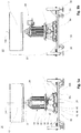
- Fig. 1 . 1a and 1b is a laboratory centrifuge 10 according to the invention in a perspective view, see Fig. 1 , a rear view, see Fig. 1a , and a view from her left side, please refer Fig. 1b represented.
- Fig. 1b represents.
- essential elements is omitted in these figures on the presentation of a centrifuge housing.
- a motor 18 which is at the same time the axis of rotation of the centrifuge 10, located at the upper end of a rotor 12 which receives containers with centrifuging.
- the rotor 12 is supported on a motor shaft 14 which is driven by the underlying motor 18.
- the motor 18 is surrounded by a motor housing 24.
- the motor shaft 14 is rotatably connected in a known manner with the rotor 12, for example via a Dahlnutprofil not shown here.
- the motor housing 24 On the side facing away from the rotor 12 side of the motor 18, the motor housing 24 is provided with equally spaced mounting feet 20, via which the motor 18 is fixedly connected to an upper support plate 32 of a bearing unit 30.
- the bearing unit 30 is used to support the motor 18 and the damping of forces resulting from the rotation of the rotor 12.
- a mechanical limit switch 60 Adjacent to the motor housing 24, a mechanical limit switch 60 is arranged, which is fixedly connected by a conventional screw with the centrifuge housing, not shown.
- the mechanical limit switch 60 is so spaced from the motor housing 24, that no contact between the mechanical limit switch 60 and the motor housing 24 is formed during trouble-free operation with tumbling motion of the rotor 12 within the usual tolerance limits.
- a contact between the mechanical limit switch 60 and the motor housing 24 In the case of a no longer compensatable over the bearing unit 30 tumbling motion of the rotor 12 and a consequent, lying outside the tolerance limits, horizontal displacement of the axis of rotation 14a and consequently of the motor 18, a contact between the mechanical limit switch 60 and the motor housing 24. This contact leads to an emergency shutdown of the centrifuge 10 via an in Fig. 3 described control and evaluation unit 90th
- a lower support plate 38 On the side facing away from the motor 18 side of the bearing unit 30 is a lower support plate 38. On the lower support plate 38 are provided as damping elements inclined rubber-metal elements 36, which in turn fixed at about the same angle struts 34 with the upper support plate 32 are connected. With respect to the longitudinal axis 14a are in principle angles of between 10 ° and 42 ° advantageous as angles of incidence ⁇ for the rubber-metal elements 36 and the associated struts 34, since the forces are based on imbalance, upon rotation of the rotor 12 in the region of this Angle act. For the present embodiment of the centrifuge 10, an angle of incidence ⁇ of 21 ° has proven particularly suitable.
- a mass member 40 is provided, which is fixedly connected to the struts 34 and the rubber-metal elements 36.
- the centrifuge 10 is rotatably mounted on a support member 54.
- a first elastic tab 48 can be seen between each pair of mounting feet 20, each receiving the upper support plate 32 facing the end of a strut 34 and the respective strut 34 resiliently connects to the upper support plate 32.
- the first elastic tabs 48 may also be separate components that are welded to the upper support plate 32, for example. However, it increases the stability of the bearing unit 30 when the first elastic tabs 48, as in the illustrated embodiment, are formed integrally with the upper support plate 32 and the same material as the upper support plate 32, for example by a punching and bending process.
- the lower boundary of the bearing element 30 is formed by a lower support plate 38, which is connected via second elastic tabs 50 with the rubber-metal elements 36. Between the lower support plate 38 and the upper support plate 32 is the mass element 40.
- the mass element 40 consists of three superimposed plates.
- a fixing plate 44 is arranged, which is resiliently connected via third elastic tabs 52 with the rubber-metal elements 36 and with the struts 34.
- a disk-shaped upper ground plate 42 and a disk-shaped lower ground plate 46 are arranged, both of which are fixedly connected to the fixing plate 44.
- the second elastic tabs 50 and the third elastic Tabs 52 are in this embodiment, analogous to the first elastic tabs 48 integral with the respective associated lower support plate 38 and the fixing plate 44 and formed of the same material as the respective associated plate.
- the bearing unit is connected via the lower support plate 38 by screw 56 fixed to the support member 54.
- the support member 54 has at its four corners legs 58 and the legs adjacent arranged rollers 59, with which the centrifuge 10 stands on the ground.
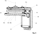
- Fig. 2 shows the arrangement of the distance sensor 80 in detail.
- the distance sensor 80 is embodied as an inductive sensor and comprises a sensor head 80a into which an induction coil (not shown for reasons of clarity) is introduced.
- the sensor head 80a is inserted in a third elastic tab 52 and has an effective axis 36b, which runs parallel to the spring axis 36a.
- a metal head 80 c is arranged, which cooperates with the sensor head 80 a.
- the metal head 80c is bolted to the second elastic tab 50.
- the metal head 80c on a threaded pin which engages in a bore of the second elastic tab 50 and secured with a nut 80b applied to the threaded pin.
- the longitudinal extension of the rubber-metal elements 36 changes along the spring axis 36 a.
- the distance between the third elastic tab 52 and its associated second elastic tab 50 changes.
- the changes in the distance can be accurately measured by the distance sensor 80, and based on the measured data is a calculation of imbalance, especially at low revolutions of the centrifuge 1000rpm, possible.
- Fig. 3 shows a schematic view of the control and evaluation unit 90.
- the control and evaluation unit 90 is arranged in an assembly with a segment disk 84, a fork light barrier 82, a reflex light sensor 86 and an acceleration sensor 88 below the motor 18.
- the in Fig. 2 distance sensor 80 shown, the fork light barrier 82, the reflex light sensor 86 and the acceleration sensor 88 and an unillustrated arranged on the centrifuge housing control panel with an integrated display unit are connected to the control and evaluation unit 90.
- Further distance sensors 88 may be arranged in the region of the struts 34, for example on the first or second lug 50, 52.
- control unit 90 is an unillustrated electrical switch for switching off the centrifuge 10 in Incident case provided.
- the electrical switch is designed as a normally closed contact and connected in series with the mechanical limit switch 60, which is likewise designed as an NC contact, so that when the two switches are opened, the centrifuge 10 is switched off.
- the segment disc 84 is concentric with the rotation in Fig. 4 Not shown motor shaft 14 is connected so that it rotates during operation of the centrifuge 10 about the rotation axis 14 a.
- motor shaft 14 is connected so that it rotates during operation of the centrifuge 10 about the rotation axis 14 a.
- recesses 84a are provided on the segment disc 84 circumferentially at equal intervals 30 recesses 84a are provided.
- the segment disc 84 partially encompassing fork light barrier 82 can be determined on the basis of the recesses 84a, the speed of the centrifuge 10.
- a disc 85 is provided above the segment disc 84, which has a cam 85a.
- the cam 85a serves as an absolute reference for a 0 ° position, for the detection of which a light reflection key 86 is provided.
- the acceleration sensor 88 arranged adjacent to the fork light barrier 82 is active in three spatial axes x, y and z and serves to detect imbalances, in particular at rotational speeds> 1000 rpm.
- FIG. 4 schematically a method for detecting an imbalance in a centrifuge 10 according to the invention is shown.
- fork light barrier 82 in conjunction with the reflex light sensor 86 and acceleration sensor 88 of the control and evaluation unit 90 measurement data for detecting unbalance provided 100. These measurement data are evaluated in the control and evaluation unit 90 102 and aligned with two predetermined characteristics 104th
- the imbalance is classified as insignificant and the operation continues without further treatment 106. If the measured data are below the first characteristic curve, the imbalance is classified as insignificant and the operation continues without further treatment 106. If the measured data exceeds the first characteristic curve, but is still below the second characteristic curve, a display unit is actuated 108 and a corresponding indication or a Warning is issued 110. However, the operation continues 106. On the other hand, if the measured data also exceed the second characteristic, the display unit and the motor 18 are activated at the same time. A warning is issued 110 on the display unit and the motor 18 is turned off 114.
Description
Die Erfindung betrifft eine Zentrifuge gemäß der im Oberbegriff des Patentanspruches 1 angegebenen Art und ein Verfahren zur Erfassung von Unwuchten in der Zentrifuge gemäß der im Oberbegriff des Patentanspruches 14 angegebenen Art.The invention relates to a centrifuge according to the type specified in the preamble of
Aus der
Von Nachteil ist bei dieser Lösung zum einen, dass durch die verwendeten Sensoren nur die Amplituden-Änderung erfasst wird. Über Ursache und Ursprung von Unwuchten können keine oder nur bedingt Aussagen getroffen werden. Daher ist es schwierig, Maßnahmen, wie die Ausgabe von Warnmeldungen oder das Abschalten der Zentrifuge auf Grundlage der Änderung der Amplitude, differenziert zu gestalten, insbesondere unter Berücksichtigung der Drehzahl.The disadvantage of this solution on the one hand, that only the amplitude change is detected by the sensors used. About cause and origin of imbalances, no or only limited statements can be made. Therefore, it is difficult to differentiate measures such as the issuance of warning messages or the shutdown of the centrifuge based on the change in the amplitude, particularly in consideration of the rotational speed.
Aufgabe der Erfindung ist es daher, eine Zentrifuge gemäß der im Oberbegriff des Patentanspruches 1 angegebenen Art zu schaffen, die unter Vermeidung der genannten Nachteile neben dem bloßen Erkennen einer Unwucht auch Aussagen über die Ursache und den Ursprung der Unwucht ermöglicht. Ferner soll die Zentrifuge derart weitergebildet werden, dass beim Erfassen einer Unwucht differenzierte Maßnahmen in Abhängigkeit der Drehzahl ergriffen werden können.The object of the invention is therefore to provide a centrifuge according to the type specified in the preamble of
Diese Aufgabe wird für die Zentrifuge durch die kennzeichnenden Merkmale des Patentanspruches 1 in Verbindung mit seinen Oberbegriffsmerkmalen gelöst. Für das Verfahren wird die Aufgabe durch die Merkmale des Patentanspruches 14 gelöst.This object is achieved for the centrifuge by the characterizing features of
Der Erfindung liegt die Erkenntnis zugrunde, dass ein Distanzsensor wesentlich aussagekräftigere Daten über Unwuchten und deren Ursache/Ursprung liefert, wenn die Wirkachse des Distanzsensors parallel oder in einem Winkel kleiner als 90° oder im spitzen Winkel zur Drehachse verläuft, als wenn die Wirkachse des Distanzsensors senkrecht zur Drehachse verläuft. Zudem liegt der Erfindung die weitere Erkenntnis zugrunde, dass differenziertere Maßnahmen bei Auftreten von Unwuchten ergriffen werden können, wenn als Grundlage die Amplitude der von den Sensoren bereitgestellten Signale selbst dient, an Stelle der Änderung dieser Amplitude.The invention is based on the finding that a distance sensor provides significantly more informative data about imbalances and their cause / origin, when the effective axis of the distance sensor parallel or at an angle less than 90 ° or at an acute angle to the axis of rotation, as if the axis of action of the distance sensor runs perpendicular to the axis of rotation. In addition, the invention is based on the further realization that more differentiated measures can be taken in the event of imbalances, if the amplitude of the signals provided by the sensors themselves serves as the basis, instead of the change in this amplitude.
Nach der Erfindung weist die Zentrifuge folgende Elemente auf: ein Gehäuse; einen Rotor zur Aufnahme von Behältern mit Zentrifugiergut; eine Antriebswelle, auf der der Rotor gelagert ist; einen Motor, der über die Antriebswelle den Rotor antreibt; eine Lagereinheit mit jeweils eine Federachse umfassenden Dämpfungselementen, welche den Motor mit der Antriebswelle und den Rotor trägt; eine Sensoreinheit zur Erfassung der Drehzahl; einen Distanzsensor zur Ermittlung von Unwuchten der aus Rotor, Motor mit Antriebswelle gebildeten Dreheinheit; einen Beschleunigungssensor zur Ermittlung von Unwuchten der Dreheinheit; und eine Steuer- und Auswerteeinheit, welche die Daten der Sensoren auswertet. Dabei erfasst der Distanzsensor in einer Wirkachse Distanzänderungen. Zudem ist die Wirkachse zur Drehachse des Rotors so ausgerichtet, dass zumindest in einer Projektion auf eine zur Wirkachse parallele Ebene durch die Drehachse des Rotors sich ein Winkel zwischen der Wirkachse und der Drehachse von kleiner als 90° einschließlich 0° ergibt. Dies ist von Vorteil, da so auch eine Taumelbewegung/Abweichung der Dreheinheit aus der Mittellage erfasst werden kann und folglich aussagekräftigere Daten erhalten werden als bei einer horizontalen Erfassung der Auslenkung.According to the invention, the centrifuge comprises the following elements: a housing; a rotor for receiving containers with centrifuging; a drive shaft on which the rotor is mounted; a motor that drives the rotor via the drive shaft; a bearing unit, each with a spring axis comprising damping elements, which carries the motor with the drive shaft and the rotor; a sensor unit for detecting the rotational speed; a distance sensor for determining imbalances of the rotary unit formed from rotor, motor with drive shaft; an acceleration sensor for detecting imbalances of the rotary unit; and a control and evaluation unit, which evaluates the data of the sensors. The distance sensor detects distance changes in an axis of action. In addition, the axis of action is aligned with the axis of rotation of the rotor so that at least in a projection on a plane parallel to the axis of action through the axis of rotation of the rotor results in an angle between the axis of action and the axis of rotation of less than 90 °, including 0 °. This is advantageous, as it is also possible to detect a tumbling motion / deviation of the rotary unit from the central position and consequently obtain more meaningful data than with a horizontal detection of the deflection.
In einer bevorzugten Ausführungsform ist die Wirkachse des Distanzsensors parallel zur Federachse ausgerichtet, da die Beanspruchung der Federung ein zuverlässiger Indikator für Unwuchten und deren Stärke ist und eine parallele Anordnung des Distanzsensors zur Federachse eine genaue Messung ermöglicht.In a preferred embodiment, the effective axis of the distance sensor is aligned parallel to the spring axis, since the stress of the suspension is a reliable indicator of imbalances and their strength and allows a parallel arrangement of the distance sensor to the spring axis accurate measurement.
Eine besonders genaue Messung kann erreicht werden, wenn Federachse und Wirkachse des Distanzsensors identisch sind. Dadurch wird auch die Konstruktion vereinfacht, da der Distanzsensor leicht in die Federung integriert werden kann.A particularly accurate measurement can be achieved if the spring axis and the effective axis of the distance sensor are identical. This also simplifies the design, as the distance sensor can be easily integrated into the suspension.
Als Drehsensoren können dabei zum Beispiel magnetische oder induktive Sensoren eingesetzt werden. Als besonders gut geeignet haben sich jedoch Lichtschranken, wie Gabellichtschranken, da sie in Verbindung mit einer Segmentscheibe gleichzeitig auch zur Erfassung der Position verwendbar sind. Hierauf wird später noch genauer eingegangen.As a rotation sensors can be used, for example, magnetic or inductive sensors. However, photoelectric barriers, such as forked light barriers, are particularly suitable because they can also be used to detect the position in conjunction with a segmented disc. This will be discussed in more detail later.
In einer weiteren vorteilhaften Ausgestaltung sind zumindest zwei Beschleunigungssensoren zur Ermittlung von Unwuchten in einem durch drei zueinander senkrecht verlaufende Raumachsen definierten Raum vorgesehen, wobei jeder Beschleunigungssensor in einer vom anderen Beschleunigungssensor unterschiedlichen Raumachse wirksam ist. Durch die Auswertung von Daten zur Beschleunigung bezüglich mehr als nur einer Achse kann eine Unwucht noch genauer erfasst und auch Aussagen über die Ursache für die Unwucht getroffen werden, wie im Folgenden noch erläutert werden wird.In a further advantageous embodiment, at least two acceleration sensors are provided for determining imbalances in a space defined by three mutually perpendicular spatial axes, each acceleration sensor being effective in a spatial axis different from the other acceleration sensor. By evaluating data for acceleration with respect to more than one axis, an imbalance can be detected even more accurately and statements about the cause of the imbalance can also be made, as will be explained below.
Insbesondere ist eine der Raumachsen, in der ein Beschleunigungssensor wirksam ist, die Raumachse in vertikaler Richtung. Denn während aufgrund einer erfassten horizontalen Beschleunigung, also entlang der x- und/oder y-Raumachse, nur die horizontale Auslenkung der Drehachse ermittelt werden kann, ist es aufgrund einer zusätzlich erfassten vertikalen Beschleunigung möglich, eine Taumelbewegung zu ermitteln. Des Weiteren können daraus Rückschlüsse über die Ursache und über den Ursprung der Unwucht gezogen werden, wenn beispielsweise über eine Segmentscheibe des Drehzahlsensors mit einer Absolut-Referenz (0°-Position) und über Lichtschranken die Rotation und der jeweilige Drehwinkel bezogen auf die Ausgangsstellung/Nullstellung erfasst wird. Denn über diese Daten ist dann feststellbar, wo innerhalb der Dreheinheit die Unwucht herrührt.In particular, one of the spatial axes in which an acceleration sensor is effective, the spatial axis in the vertical direction. Because while due to a detected horizontal acceleration, ie along the x and / or y-axis, only the horizontal deflection of the axis of rotation can be determined, it is possible due to an additionally detected vertical acceleration to determine a wobbling motion. In addition, conclusions can be drawn about the cause and origin of the imbalance, if, for example, via a segment disc of the speed sensor with an absolute reference (0 ° position) and via light barriers, the rotation and the respective rotation angle relative to the starting position / zero position is detected. For it is then possible to determine via these data where the unbalance originates within the turntable.
Gemäß einem Aspekt der Erfindung ist die Federachse so ausgerichtet, dass sie die Drehachse schneidet. Dies ist eine technisch einfach zu realisierende Anordnung der Dämpfungselemente, in die sich der Distanzsensor gut integrieren lässt.According to one aspect of the invention, the spring axis is aligned so that it intersects the axis of rotation. This is a technically easy to implement arrangement of the damping elements, in which the distance sensor can be well integrated.
Vorzugsweise sind auch die Wirkachse und die Federachse identisch. So kann der Distanzsensor noch leichter in die Dämpfungselemente integriert werden und direkt den Federweg der Dämpfungselemente erfassen, an Hand dessen sich dann die Abweichung des Rotors aus der Mittellage bestimmen lässt.Preferably, the axis of action and the spring axis are identical. Thus, the distance sensor can be more easily integrated into the damping elements and directly detect the travel of the damping elements, on the basis of which then the deviation of the rotor can be determined from the center position.
In einer weiteren vorteilhaften Ausgestaltung ist in der Steuer- und Auswerteeinheit eine erste Kennlinie gespeichert, welche erste Grenzwerte in Abhängigkeit der Drehzahl für die durch den Beschleunigungssensor und/oder den Distanzsensor erfassten, die Unwucht der Dreheinheit beschreibenden Amplitude bildet. Die ersten Grenzwerte sind so definiert, dass ein Überschreiten einen Handlungsbedarf signalisiert, jedoch noch keine unmittelbare Gefahr für die Sicherheit der Zentrifuge oder des Nutzers besteht. Somit dienen die ersten Grenzwerte dazu, dass bei nicht sicherheitsrelevanten Problemen innerhalb der Zentrifuge eine Warnstufe eingeleitet werden kann und weiterführende Maßnahmen vorerst vermieden werden können.In a further advantageous embodiment, a first characteristic is stored in the control and evaluation unit, which first limit values as a function of the speed for the detected by the acceleration sensor and / or the distance sensor, the imbalance of the rotary unit descriptive amplitude forms. The first limit values are defined in such a way that exceeding them indicates a need for action but there is no immediate danger to the safety of the centrifuge or the user. Thus, the first limit values serve that a warning level can be initiated for non-safety-relevant problems within the centrifuge and further measures can be avoided for the time being.
Bei einer vorteilhaften Weiterbildung der Erfindung ist in der Steuer- und Auswerteeinheit eine zweite Kennlinie gespeichert, welche zweite Grenzwerte in Abhängigkeit der Drehzahl für die durch den Beschleunigungssensor und/oder den Distanzsensor erfassten, die Unwucht der Dreheinheit beschreibenden Amplitude bildet. Dabei sind die zweiten Grenzwerte so definiert, dass ein Überschreiten Gefahr und unmittelbaren Handlungsbedarf bedeutet. Somit dienen die zweiten Grenzwerte dazu, dass bei sicherheitsrelevanten Problemen innerhalb der Zentrifuge umgehend weiterführende Maßnahmen eingeleitet werden können, die die Sicherheit der Zentrifuge und des Nutzers gewährleisten.In an advantageous development of the invention, a second characteristic curve is stored in the control and evaluation unit which forms second limit values as a function of the rotational speed for the amplitude recorded by the acceleration sensor and / or the distance sensor and describing the imbalance of the rotary unit. The second limit values are defined in such a way that exceeding them means danger and immediate need for action. Thus, the second limit values serve to promptly initiate further measures in the event of safety-relevant problems within the centrifuge, which ensure the safety of the centrifuge and the user.
Günstig ist es, wenn die Steuer- und Auswerteeinheit bei Erreichen des ersten Grenzwerts eine akustische und/oder optische Signaleinheit aktiviert und/oder eine beispielsweise im Bedienteil der Zentrifuge integrierte Anzeigeeinheit ansteuert, über die die Auswertung sowie Anweisungen an den Nutzer für die zu ergreifenden Maßnahmen angezeigt werden. Dadurch erhält der Nutzer rechtzeitig ausreichend Informationen zur Behebung von Problemen, während der Betrieb der Zentrifuge vorerst aufrechterhalten werden kann.It is favorable when the control and evaluation unit activates an acoustic and / or optical signal unit when reaching the first limit value and / or activates a display unit integrated, for example, in the operating part of the centrifuge, via which the evaluation and instructions to the user for the measures to be taken are displayed. As a result, the user receives sufficient information in good time to remedy problems, while the operation of the centrifuge can be maintained for the time being.
Um die Sicherheit der Zentrifuge und des Nutzers in kritischen Situationen zu gewährleisten, ist es vorgegeben, dass die Steuer- und Auswerteeinheit bei Erreichen des zweiten Grenzwerts den Motor der Dreheinheit oder die Zentrifuge insgesamt abschaltet.In order to ensure the safety of the centrifuge and the user in critical situations, it is prescribed that the control and evaluation unit shuts down the motor of the rotary unit or the centrifuge when the second limit value is reached.
Vorteilhaft ist es, wenn die Steuer- und Auswerteeinheit auch bei Erreichen des zweiten Grenzwerts eine akustische und/oder optische Signaleinheit aktiviert und/oder eine Anzeigeeinheit ansteuert, über die die Auswertung sowie Anweisungen an den Nutzer für die zu ergreifenden Maßnahmen angezeigt werden. Dadurch werden in kritischen Situationen die Zeiten für Ursachenforschung und Problembehebung erheblich verkürzt und der Bedienkomfort verbessert.It is advantageous if the control and evaluation unit activates an acoustic and / or optical signal unit even when the second limit value is reached and / or actuates a display unit via which the evaluation and instructions to the user for the measures to be taken are displayed become. As a result, the times for cause research and troubleshooting are significantly reduced in critical situations and the ease of use is improved.
Günstig ist es ferner, wenn in der Steuer- und Auswerteeinheit auch ein Datenlogger vorgesehen ist, der sämtliche ermittelte Daten aufzeichnet. Die Daten können dann nach dem Ende des Betriebs der Zentrifuge, beispielsweise über einen USB-Port, ausgelesen und für Wartung, Fehlerbehebung, Produkt Lifecycle-Management etc. zur Verfügung gestellt werden.It is also favorable if a data logger is also provided in the control and evaluation unit, which records all the determined data. The data can then be read after the end of the operation of the centrifuge, for example via a USB port, and made available for maintenance, troubleshooting, product lifecycle management, etc.
Gemäß einem Aspekt der Erfindung wird zur Erkennung von Unwuchten in einem Drehzahlbereich von kleiner als 1000rpm der Distanzsensor verwendet. Dadurch kann eine Unwucht schon bei niedrigeren Drehzahlen erkannt werden, bei denen die Beschleunigungskräfte noch zu gering sind, um von Beschleunigungssensoren zuverlässig erfasst zu werden.According to one aspect of the invention, the distance sensor is used to detect imbalances in a speed range of less than 1000rpm. As a result, an imbalance can be detected even at lower speeds, in which the acceleration forces are still too low to be reliably detected by acceleration sensors.
Gemäß einem weiteren Aspekt der Erfindung wird zur Erkennung von Unwuchten in einem Drehzahlbereich von größer als 1000rpm der Beschleunigungssensor verwendet. Der Beschleunigungssensor ist in diesem höheren Drehzahlbereich besser geeignet als der Distanzsensor, da bei dieser Frequenz eine Messung der Beschleunigung genauere Daten liefert als eine Messung der Distanz.According to a further aspect of the invention, the acceleration sensor is used to detect imbalances in a speed range of greater than 1000rpm. The acceleration sensor is better suited than the distance sensor in this higher speed range because at this frequency, measuring the acceleration provides more accurate data than measuring the distance.
Allerdings sind die Drehzahlbereiche, in denen jeweils der Distanzsensor oder der Beschleunigungssensor zuverlässigere Daten liefern, stark von der Konstruktion der Zentrifuge, insbesondere ihrer Dämpfung, abhängig. Es ist daher vorteilhaft, die Drehzahlbereiche über die Firmware konfigurierbar zu machen.However, the speed ranges in each of which the distance sensor or the acceleration sensor provide more reliable data, highly dependent on the construction of the centrifuge, in particular their attenuation. It is therefore advantageous to make the speed ranges configurable via the firmware.
Die Aufgabe wird für das Verfahren dadurch gelöst, dass in Abhängigkeit der fortlaufenden Umdrehung Messwerte der Sensoren ermittelt werden und aus den Messwerten ein Mittelwert gebildet und mit dem entsprechenden Wert der Kennlinie verglichen wird, wobei bei einem Mittelwert oberhalb der Kennlinie weitere Maßnahmen initiiert werden, wie Abschalten des Motors der Dreheinheit, reduzieren der Drehzahl des Rotors, Aktivieren von akustischen und/oder optischen Signalen und/oder Ausgabe von Informationen über eine Anzeigeeinheit und Ähnliches.The object is achieved for the method in that measured values of the sensors are determined as a function of the continuous revolution and an average value is formed from the measured values and compared with the corresponding value of the characteristic, with further measures being initiated at an average value above the characteristic Turning off the motor of the rotary unit, reducing the speed of the rotor, activating acoustic and / or optical signals and / or output of information about a display unit and the like.
Mittels der erfindungsgemäßen Vorrichtung und des Verfahrens soll eine mögliche Unwucht der Dreheinheit der Zentrifuge erkannt werden und die Steuer- und Auswerteeinheit vorbestimmt darauf reagieren. Darüber hinaus sollen Laufdaten gesammelt, gespeichert und zur Auswertung bereitgestellt werden, insbesondere um Rückschlüsse für die Belastung und die Lebensdauer der Zentrifuge und deren Bauteile gewinnen zu können. Hierzu werden in einem Datenlogger pro Zentrifugenlauf folgende Daten aufgezeichnet: Dauer der Zentrifugation, maximale Drehzahl, maximale Unwuchtamplitude, Drehzahl beim Auftreten der maximalen Unwuchtamplitude, Unwuchtwinkel, Mittellagenabweichung und Systemzustandsindikatoren (Flags). Zusätzlich können bei Bedarf weitere relevante Daten aufgezeichnet werden, wie beispielsweise Temperatur oder Geräusche.By means of the device and the method according to the invention, a possible imbalance of the rotary unit of the centrifuge should be detected and the control and evaluation unit should react in a predetermined manner. In addition, run data should be collected, stored and made available for evaluation In particular, to be able to draw conclusions about the load and the life of the centrifuge and its components. For this purpose, the following data are recorded in a data logger per centrifugal run: duration of the centrifugation, maximum speed, maximum unbalance amplitude, speed at the occurrence of the maximum imbalance amplitude, imbalance angle, center position deviation and system state indicators (flags). In addition, further relevant data can be recorded as needed, such as temperature or noise.
Beispielsweise kann es durch die ermittelten Daten zu einem Abschalten des Motors des Rotors oder der ganzen Zentrifuge kommen, wenn die Unwucht den durch eine Kennlinie definierten Grenzwert überschreitet. Zusätzlich oder alternativ kann es Hinweise für den Service bez. dem Verschleißzustand der Dämpfungselemente, beispielsweise von bei einem Motorständer verwendeten Gummi-Metall-Elementen, geben. Möglich sind auch Hinweise für den Benutzer, durch welches Behältnis des Rotors die Unwucht hervorgerufen wird evtl. durch falsche Beladung. Zudem kann auch eine Hilfestellung im Servicefall zum Auswuchten des Rotors über eine Anzeigevorrichtung ausgegeben werden.For example, the determined data may cause the motor of the rotor or the entire centrifuge to be switched off if the unbalance exceeds the limit defined by a characteristic curve. Additionally or alternatively, there may be references for the service bez. the state of wear of the damping elements, such as rubber-metal elements used in a motor stand, give. Also possible are instructions for the user, through which container of the rotor the imbalance is caused possibly by incorrect loading. In addition, assistance in the event of servicing for balancing the rotor can also be output via a display device.
Der Drehsensor zur Erfassung der Rotation kann dabei wie folgt ausgebildet sein: An der Motorachse ist eine Segmentscheibe mit 30 in gleichem Abstand angeordnete Aussparungen sowie eine einzelne Nocke in der 0°-Position (Absolut-Referenz) befestigt. Über eine Lichtschranke, beispielsweise eine Gabellichtschranke, wird der aktuelle Drehwinkel unter Einbeziehung der Flankenwechsel in 6°-Schritten erfasst, 60 mal 6° sind 360°. Über eine zweite Gabellichtschranke, die so angeordnet ist, dass sie ein zum Signal der ersten Gabellichtschranke um 90° versetztes Signal liefert, wird die Drehrichtung erfasst. Über einen Reflexlichttaster wird die 0°-Position erfasst.The rotation sensor for detecting the rotation can be embodied as follows: A segment disk with 30 identically spaced recesses and a single cam in the 0 ° position (absolute reference) are fastened to the motor axis. Via a light barrier, for example a forked light barrier, the current angle of rotation, including the edge changes, is recorded in 6 ° increments, 60 times 6 ° are 360 °. Via a second forked light barrier, which is arranged so that it provides a signal to the first fork light barrier offset by 90 ° signal, the direction of rotation is detected. A reflex light sensor detects the 0 ° position.
Zur Erfassung der zur Unwucht-Erkennung relevanten Daten werden, wie oben ausgeführt wurde, vier Sensoren eingesetzt, nämlich der Drehsensor, der Beschleunigungssensor für die Erfassung der Beschleunigung in einer ersten Raumachse, der Beschleunigungssensor für die Erfassung in der zweiten Raumachse, der Distanzsensor. Zusätzlich kann auch ein weiterer Beschleunigungssensor für die Erfassung der Beschleunigung der dritten Raumachse vorgesehen sein.As described above, four sensors are used to detect the data relevant for unbalance detection, namely the rotation sensor, the acceleration sensor for detecting acceleration in a first spatial axis, the acceleration sensor for detection in the second spatial axis, the distance sensor. In addition, it is also possible to provide a further acceleration sensor for detecting the acceleration of the third spatial axis.
Die drei Beschleunigungssensoren sind insbesondere als ein Dreiachsen-Beschleunigungssensor ausgebildet. Somit sind alle drei Beschleunigungssensoren in einer Baueinheit zusammengefasst. Diese ist dann vorzugsweise direkt auf einem Elektronikboard montiert, das im Bereich eines unteren Motorlagers nahe der Welle befestigt ist. Alternativ kann die Baueinheit auch im Rotor angeordnet werden.The three acceleration sensors are designed in particular as a three-axis acceleration sensor. Thus, all three acceleration sensors are combined in one unit. This is then preferably mounted directly on an electronic board, which is mounted in the region of a lower engine mount near the shaft. Alternatively, the assembly can also be arranged in the rotor.
Der Distanzsensor kann als induktiver Näherungssensor ausgebildet sein. Der Messbereich umfasst insbesondere Änderungen von 4 mm, vorzugsweise bis zu 6 mm. Es werden dabei relative Abstandsänderungen zwischen einer Trägerplatte bzw. einer zweiten elastischen Lasche und einer Fixierplatte bzw. einer dritten elastischen Lasche des Motorständers erzeugt. Die Justage kann mittels einer einfachen mechanischen Lehre erfolgen und erfordert keine besondere Präzision.The distance sensor can be designed as an inductive proximity sensor. The measuring range comprises in particular changes of 4 mm, preferably up to 6 mm. Relative changes in distance between a carrier plate or a second elastic tab and a fixing plate or a third elastic tab of the motor stator are generated. The adjustment can be done by means of a simple mechanical teaching and requires no special precision.
Die vertikale Schwingung der Trägerplatte der Zentrifuge wird zwar auch von der Konstruktion der Zentrifuge beeinflusst. Erfahrungsgemäß zeigt sie aber bei Unwucht ein charakteristisches Maximum bei ca. 150-200 rpm. Dieses Maximum kann nur mit dem Distanzsensor erfasst werden, da bei diesen Drehzahlen die Beschleunigungskräfte für den Messbereich des Beschleunigungssensors noch zu gering sind. Da eine Unwucht möglichst früh, also bei niedrigen Drehzahlen erkannt werden soll, muss hierzu der Distanzsensor eingesetzt werden. Bei Drehzahlen oberhalb von ca. 1000 rpm eignet sich der Beschleunigungssensor besser zur eindeutigen Erkennung einer Unwucht. Eine Messung der Abweichung aus der Mittellage, nämlich ein Aufrichten des Rotors bei hohen Drehzahlen, ist wiederum nur mit dem Distanzsensor möglich.Although the vertical vibration of the carrier plate of the centrifuge is also influenced by the design of the centrifuge. According to experience, however, it shows a characteristic maximum at approx. 150-200 rpm in the event of imbalance. This maximum can only be detected with the distance sensor, since at these speeds the acceleration forces for the measuring range of the acceleration sensor are still too low. Since an imbalance should be detected as early as possible, ie at low speeds, the distance sensor must be used for this purpose. At speeds above approx. 1000 rpm, the acceleration sensor is better suited for unambiguously detecting an imbalance. A measurement of the deviation from the central position, namely an erection of the rotor at high speeds, is again possible only with the distance sensor.
Es ist zudem denkbar, in jeder Federachse, beispielsweise oberhalb eines Dämpfungselements, jeweils einen Distanzsensor zur Datenerfassung vorzusehen. Anhand der erfassten Daten kann eine falsche/unsymmetrische Beladung, die zu einer erhöhten Unwucht während der Zentrifugation führen würde, von der Auswerteeinheit unmittelbar vor Inbetriebnahme der Zentrifuge erkannt werden. Über eine Anzeigeeinheit wird der Benutzer dann vor dem Start gewarnt oder die Steuereinheit kann einen Start von vornherein verhindern.It is also conceivable to provide in each spring axis, for example above a damping element, in each case a distance sensor for data acquisition. On the basis of the acquired data, an incorrect / unsymmetrical loading, which would lead to an increased imbalance during the centrifugation, can be recognized by the evaluation unit immediately before the centrifuge is put into operation. Via a display unit, the user is then warned before starting or the control unit can prevent a start from the outset.
Die Berechnung des für die Unwucht-Bewertung verwendeten Wertes erfolgt insbesondere wie folgt:
Die Steuer- und Auswerteeinheit erfasst kontinuierlich mit einer Frequenz von 9,6 kHz auf vier unterschiedlichen Kanälen folgende Messwerte: Mittels des Distanzsensors die Distanz zwischen Trägerplatte und Fixierplatte, mittels des Beschleunigungssensors die Beschleunigung längs der x-Achse, mittels des Beschleunigungssensors die Beschleunigung längs der y-Achse und mittels des Beschleunigungssensors die Beschleunigung längs der z-Achse. Es sind somit vier Sensoren im Einsatz, der Distanzsensor, der Beschleunigungssensor für die x-Achse, der Beschleunigungssensor für die y-Achse, der Beschleunigungssensor für die z-Achse.In particular, the value used for the unbalance evaluation is calculated as follows:
The control and evaluation unit continuously records the following measured values on a frequency of 9.6 kHz on four different channels: The distance between the carrier plate and fixing plate by means of the distance sensor, the acceleration along the x-axis by means of the acceleration sensor, the acceleration along the x-axis by means of the acceleration sensor y-axis and by means of the acceleration sensor, the acceleration along the z-axis. There are thus four sensors in use, the distance sensor, the acceleration sensor for the x-axis, the acceleration sensor for the y-axis, the acceleration sensor for the z-axis.
Dadurch, dass die Messwerte auf vier unterschiedlichen Kanälen übertragen werden, stehen diese gleichzeitig zur Auswertung der Steuer- und Auswerteeinheit zur Verfügung. Aus den mit 9,6 kHz erfassten Messwerten werden in Abhängigkeit zur Drehzahl Mittelwerte gebildet.Because the measured values are transmitted on four different channels, they are simultaneously available for evaluation of the control and evaluation unit. From the measured values recorded at 9.6 kHz, mean values are formed as a function of the rotational speed.
Wie ausgeführt wurde, weist der Drehsensor Aussparungen in einer Segmentscheibe auf, welche mit einer Lichtschranke zusammenwirken. Mit Beginn der Aussparung wird ein Signal solange erzeugt, bis der Lichtstrahl in Folge der Drehung der Segmentscheibe das Ende der Aussparung erreicht hat. In dieser Zeit trifft die Lichtschranke auf den zugeordneten Lichtsensor und generiert das Signal. Zu Beginn und zum Ende des Signals entstehen Signalflanken. Die Signalflanke wechselt somit zu Beginn und am Ende des Signals. Bei einem Wechsel der Signalflanke bei Drehung des Segmentrads wird von der Steuer- und Auswerteeinheit ein Mittelwert gebildet. Dieser Mittelwert basiert auf allen Messwerten eines Sensors, die seit dem letzten Flankenwechsel von diesem Sensor erfasst wurden. Die 60 Messpunkte ergeben die Signalkurve, die einen sinusähnlichen Verlauf aufweist. Je nach Sensor ergeben sich unterschiedliche Amplituden und Phasenwinkel.As has been stated, the rotation sensor has recesses in a segment disc, which interact with a light barrier. With the beginning of the recess, a signal is generated until the light beam has reached the end of the recess as a result of the rotation of the segment disc. During this time, the light barrier hits the assigned light sensor and generates the signal. Signal edges arise at the beginning and at the end of the signal. The signal edge thus changes at the beginning and at the end of the signal. When changing the signal edge during rotation of the segment wheel, an average value is formed by the control and evaluation unit. This average value is based on all measured values of a sensor that have been acquired by this sensor since the last edge change. The 60 measuring points yield the signal curve, which has a sinusoidal course. Depending on the sensor, different amplitudes and phase angles result.
Pro Umdrehung ergibt sich pro Sensor eine Signalkurve aus den 60 Messpunkten. Von dieser Signalkurve wird für jeden Sensor der Effektivwert des Signales (RMS) und der DC-Offset ermittelt. Die Signalkurve wird um den DC-Offset, der sich aus dem Mittelwert der 60 Messpunkte ergibt, korrigiert, um den reinen Wechselsignalanteil zu erhalten. Dieser ist somit symmetrisch zu Null.Per revolution, one signal curve per sensor results from the 60 measuring points. From this signal curve, the RMS value of the signal and the DC offset are determined for each sensor. The signal curve is corrected by the DC offset, which results from the average of the 60 measuring points, in order to obtain the pure alternating signal component. This is thus symmetrical to zero.
Die Effektivwerte der vier Sensoren werden in der Steuer- und Auswerteeinheit gewichtet summiert, d.h. jeder Effektivwert wird mit einem konfigurierbaren Faktor multipliziert und die Ergebnisse addiert. Das Ergebnis wird im Folgenden als Sensorensumme bezeichnet. Diese Sensorensumme wird primär für eine nachfolgend erläuterte Bewertung der Unwucht durch einen Vergleich der ermittelten Werte mit konfigurierbaren Grenzwerten verwendet. Zudem ist die Sensorensumme auch für die Ermittlung des Unwucht-Winkels notwendig.The RMS values of the four sensors are summed in the control and evaluation unit weighted, i. each RMS value is multiplied by a configurable factor and the results are added together. The result is referred to below as the sensor sum. This sensor sum is used primarily for a subsequently explained evaluation of the imbalance by comparing the determined values with configurable limit values. In addition, the sensor sum is also necessary for determining the imbalance angle.
Der Unwucht-Winkel wird wie folgt ermittelt: Der Winkel, an dem der maximale Ausschlag der Sensorensumme gemessen wird, entspricht nicht dem Winkel, an dem sich die maximale Unwucht tatsächlich befindet, da verschiedene Einflüsse, wie z.B. Drehzahl, Gewichtung der Sensoren, Höhe der Unwucht, u. ä., eine Winkelverschiebung des maximalen Ausschlags verursachen. Aus diesem Grund wird der Winkel der Unwucht und somit letztlich die Feststellung, welcher Behälter des Rotors betroffen ist, bei einer niedrigen Drehzahl und ausschließlich mit dem Distanzsensor ermittelt.The unbalance angle is determined as follows: The angle at which the maximum deflection of the sensor sum is measured does not correspond to the angle at which the maximum unbalance is actually located, since various influences such as speed, weighting of the sensors, height of the Imbalance, u. Ä., cause an angular displacement of the maximum deflection. For this reason, the angle of the unbalance and thus ultimately the determination of which container of the rotor is affected, determined at a low speed and only with the distance sensor.
Beispielsweise wird für diese exakte Bestimmung der Position die Unwucht bei einer konstanten Drehzahl, z.B. 190rpm, mit dem Distanzsensor erfasst und dabei der Drehwinkel bezogen auf einen Nullpunkt des Rotors - 0°-Position - gemessen, an dem das Sinussignal des Distanzsensors sein Maximum hat.For example, for this exact determination of the position, the unbalance at a constant speed, e.g. 190rpm, detected with the distance sensor and thereby the angle of rotation relative to a zero point of the rotor - 0 ° position - measured at which the sine signal of the distance sensor has its maximum.
Messungen zeigen, dass die Phasen des Sinussignals des Distanzsensors vom Gewicht der Unwucht abhängig sind. Beispielsweise ergibt sich zwischen 2,5g und 60g Unwucht eine Verschiebung von ca. 70° des Drehwinkels. Dieser Einfluss wird dann in der Auswerteeinheit über eine logarithmische Korrekturkurve korrigiert. Die Formel der Kurve lautet: ![]()
![]()
Der Korrekturfaktor A1 (einheitenlos) bestimmt die Verstärkung der logarithmischen Kurven der Unwuchtamplitude, der Faktor A2 (in °) bestimmt die Lage dieser Kurve.The correction factor A1 (unitless) determines the gain of the logarithmic curves of the imbalance amplitude, the factor A2 (in °) determines the position of this curve.
Die entsprechend korrigierten Daten geben die exakte Position der Unwucht im Rotor an und somit die Position des Behältnisses im Rotor, das die Unwucht verursacht. Die Auswerteeinheit teilt dem Benutzer diese Position über die Anzeigeeinheit mit, so dass der Benutzer geeignete Maßnahmen ergreifen kann.The corrected data indicates the exact position of the imbalance in the rotor and thus the position of the container in the rotor, which causes the imbalance. The evaluation unit notifies the user of this position via the display unit so that the user can take appropriate measures.
Ein weiterer Grund für die Verwendung des Distanzsensors zur Ermittlung des Unwucht-Winkels ist ferner, dass beim Abbremsen/Auslaufen die niedrige Drehzahl zwangsläufig durchlaufen wird. Der Unwucht-Winkel wird erst bei stehender Maschine für den Bediener relevant, um das Behältnis, welches als Unwucht verursachend ermittelt wurde, überprüfen zu können. Des Weiteren kann auf eine aufwändige Korrektur (Modellierung) der veränderlichen Einflüsse, wie Drehzahl, Unwucht-Gewicht, auf den Winkel verzichtet werden, da diese bei niedrigen Drehzahlen kaum ins Gewicht fallen.Another reason for using the distance sensor to determine the imbalance angle is further that the slow speed is inevitably passed through during deceleration / coasting. The imbalance angle becomes relevant to the operator only when the machine is stationary, in order to be able to check the container which was determined as causing unbalance. Furthermore, an elaborate correction (modeling) of the variable influences, such as speed, imbalance weight, can be dispensed with the angle, as these fall at low speeds hardly significant.
Die Ermittlung/Auswertung der Mittellage-Abweichung des Rotors kann wie folgt durchgeführt werden, wobei zunächst zu beachten ist, dass unabhängig von der Unwucht sich die Rotationsachse mit steigender Drehzahl durch Kreiselkräfte lotrecht ausrichtet. Hierdurch verschiebt sich die mittlere Lage, um die die Masse der Dreheinheit schwingt. Diese Verschiebung der mittleren Lage kann mit dem Distanzsensor wie folgt erfasst werden.The determination / evaluation of the center position deviation of the rotor can be carried out as follows, it being first noted that regardless of the imbalance, the axis of rotation aligns vertically with increasing speed by centrifugal forces. This shifts the middle position around which the mass of the rotary unit oscillates. This shift of the middle position can be detected with the distance sensor as follows.
Die Mittellage entspricht dem Mittelwert der 60 winkelabhängig berechneten Messpunkte des Distanzsensors innerhalb einer Umdrehung des Rotors, siehe oben im Zusammenhang mit der Berechnung des für die Unwucht-Bewertung verwendeten Wertes. Sie entspricht der absoluten Lage der Rotationsschwingung auf der Ordinate. Der Wert der Mittellage wird an zwei festgelegten Drehzahlwerten gespeichert, z. B. 500 rpm und 2.500 rpm. Die Differenz der Mittellagewerte an diesen Schwellen wird bewertet. Der Absolutwert der Differenz wird mit einer festzulegenden Maximalschwelle verglichen. Wenn die Maximalschwelle, ein erster Grenzwert überschritten wird, wird eine Warnung angezeigt, aber die Maschine nicht abgeschaltet.The center position corresponds to the mean value of the 60 angle-dependent calculated measuring points of the distance sensor within one revolution of the rotor, see above in connection with the calculation of the value used for the unbalance evaluation. It corresponds to the absolute position of the rotational vibration on the ordinate. The value of the center position is stored at two specified speed values, eg. 500 rpm and 2500 rpm. The difference of the mean values at these thresholds is evaluated. The absolute value of the difference is compared with a maximum threshold to be determined. If the maximum threshold, a first limit, is exceeded, a warning is displayed, but the machine is not shut down.
Ursachen für eine zu hohe Abweichung können sein:
- Unsachgemäße Ausrichtung der Maschine, z. B. nicht waagrecht ausgerichtet.
- Defekt(e) an den Dämpfungselementen, z.B. Gummi-Metall-Elementen des Rotorlagers.
- Improper alignment of the machine, eg. B. not aligned horizontally.
- Defect (s) on the damping elements, eg rubber-metal elements of the rotor bearing.
Vorzugsweise kann die Erkennung der maximal zulässigen Unwucht wie folgt erfolgen.Preferably, the detection of the maximum allowable unbalance can be done as follows.
Die Schwelle zur Erkennung einer unzulässigen Unwucht und folglich die Abschaltung der Maschine wird über sogenannte Abschaltfenster realisiert. Jedes Abschaltfenster besteht aus einem Datensatz, in dem konfiguriert ist, unter welchen Bedingungen die Maschine die Voraussetzungen erfüllt, damit das Abschaltfenster aktiv wird, d.h. der zugehörige Schwellwert geprüft und die Maschine ggf. abgeschaltet wird. Ein Abschaltfenster wird aktiv, wenn die aktuelle Drehzahl innerhalb der konfigurierten Drehzahlgrenzen liegt, und die aktuelle Beschleunigung innerhalb der konfigurierten Beschleunigungsgrenzen liegt, und diese Bedingungen permanent für eine konfigurierte Entprellzeit erfüllt sind, also dem vorgegebenen Zeitraum, in dem das Signal mindestens an einem Eingang der Steuer- und Auswerteeinheit anliegen muss, damit es erkannt wird und von der Steuer- und Auswerteeinheit weiterverarbeitet werden kann.The threshold for detecting an impermissible imbalance and consequently the shutdown of the machine is realized via so-called shutdown window. Each shutdown window consists of a dataset that configures under which conditions the machine meets the conditions for the shutdown window to become active, i. the associated threshold value is checked and the machine is switched off if necessary. A shutdown window becomes active when the current speed is within the configured speed limits, and the current acceleration is within the configured acceleration limits, and these conditions are permanently met for a configured debounce time, the predetermined time period during which the signal is received at least at one input Control and evaluation must be present so that it is recognized and can be further processed by the control and evaluation.
Vorzugsweise werden über eine Eingabe von Datensätzen einzelne Verfahrensschritte der Zentrifuge - z. B. Sedimentation, Separation - definiert, für die jeweils eine spezifische Behandlung beim Erkennen einer Unwucht festgelegt wird. Beispielsweise wird zwischen einem Sedimentationsschritt und einem Separationsschritt unterschieden. Die Unterscheidung erfolgt über die Festlegung von Drehzahlschwellen in unterschiedlichen Abschaltfenstern. Beispielsweise können dem Sedimentationsschritt Drehzahlen von über 1.000 rpm zugeordnet sein und dem Separationsschritt Drehzahlen von kleiner 1.000 rpm. Die Abschaltfenster sind dabei so konfiguriert, dass während der Separation keine Abschaltung durch die Steuer- und Auswerteeinheit erfolgt, um die Produktivität zu erhöhen. Der zusätzliche, in jeder Zentrifuge vorgesehene Unwucht-Endschalter bleibt davon unberührt aber jederzeit aktiv.Preferably, via an input of data sets individual process steps of the centrifuge -. B. sedimentation, separation - defined, for each of which a specific treatment is determined when detecting an imbalance. For example, a distinction is made between a sedimentation step and a separation step. The distinction is made by setting speed thresholds in different shutdown windows. For example, the sedimentation step may be associated with speeds of more than 1,000 rpm and the separation step with speeds of less than 1,000 rpm. The shutdown windows are configured in such a way that during the separation no Shutdown by the control and evaluation unit takes place in order to increase productivity. The additional unbalance limit switch provided in each centrifuge remains untouched but active at all times.
Bei Plateauphasen, d. h. wenn bei einer konstanten Drehzahl nicht beschleunigt wird, muss die Steuer- und Auswerteeinheit nicht erkennen können, ob ein Verfahrensschritt durch einen Beschleunigungs- oder Abbremsvorgang erreicht wurde, d.h. welcher Produktionsschritt gerade ausgeführt wird.In plateau phases, d. H. if it is not accelerated at a constant speed, the control and evaluation unit need not be able to detect whether a process step has been achieved by an acceleration or deceleration process, i. which production step is currently being carried out.
Weitere Vorteile, Merkmale und Anwendungsmöglichkeiten der vorliegenden Erfindung ergeben sich aus der nachfolgenden Beschreibung in Verbindung mit den in den Zeichnungen dargestellten Ausführungsbeispielen.Further advantages, features and possible applications of the present invention will become apparent from the following description in conjunction with the embodiments illustrated in the drawings.
In der Beschreibung, in den Ansprüchen und in der Zeichnung werden die in der unten aufgeführten Liste der Bezugszeichen verwendeten Begriffe und zugeordneten Bezugszeichen verwendet. In der Zeichnung bedeutet:
- Fig. 1
- eine perspektivische Ansicht der Zentrifuge nach der Erfindung, mit Trägerelement und ohne Gehäuse, wobei die Vorderseite der Zentrifuge vom Betrachter aus nach rechts gerichtet ist;
- Fig. 1a
- eine Ansicht der Rückseite der in der
Fig. 1 gezeigten Zentrifuge; - Fig. 1b
- eine Ansicht der linken Seite der in der
Fig. 1 gezeigten Zentrifuge; - Fig. 2
- eine schematische Teilansicht des in den
Fig. 1 ,1a und 1b dargestellten Distanzsensors in montiertem Zustand; - Fig. 3
- eine schematische Teilansicht der in den
Fig. 1 ,1a und 1b dargestellten Steuer- und Auswerteeinheit, und - Fig. 4
- ein Ablaufdiagramm zur Unwuchterkennung bei der Zentrifuge nach der Erfindung.
- Fig. 1
- a perspective view of the centrifuge according to the invention, with support member and without housing, the front of the centrifuge is directed from the viewer to the right;
- Fig. 1a
- a view of the back of the in the
Fig. 1 shown centrifuge; - Fig. 1b
- a view of the left side in the
Fig. 1 shown centrifuge; - Fig. 2
- a schematic partial view of the in the
Fig. 1 .1a and 1b shown distance sensor in the assembled state; - Fig. 3
- a schematic partial view of the in the
Fig. 1 .1a and 1b represented control and evaluation, and - Fig. 4
- a flow chart for unbalance detection in the centrifuge according to the invention.
In den
Entlang einer Längs- und Drehachse 14a eines Motors 18, welche zugleich die Drehachse der Zentrifuge 10 ist, befindet sich am oberen Ende ein Rotor 12, der Behälter mit Zentrifugiergut aufnimmt. Der Rotor 12 ist auf einer Motorwelle 14 gelagert, die von dem darunterliegenden Motor 18 angetrieben wird. Der Motor 18 ist von einem Motorgehäuse 24 umgeben. Die Motorwelle 14 ist in bekannter Weise drehfest mit dem Rotor 12 verbunden, beispielsweise über ein hier nicht dargestelltes Vielnutprofil.Along a longitudinal and
Auf der vom Rotor 12 abgewandten Seite des Motors 18 ist das Motorgehäuse 24 mit gleichmäßig voneinander beabstandeten Befestigungsfüßen 20 versehen, über die der Motor 18 fest mit einer oberen Trägerplatte 32 einer Lagereinheit 30 verbunden ist. Die Lagereinheit 30 dient der Lagerung des Motors 18 sowie der Dämpfung von Kräften, die von der Drehung des Rotors 12 herrühren.On the side facing away from the
Benachbart zum Motorgehäuse 24 ist ein mechanischer Endschalter 60 angeordnet, der durch eine herkömmliche Schraubverbindung mit dem nicht dargestellten Zentrifugengehäuse fest verbunden ist. Dabei ist der mechanische Endschalter 60 so vom Motorgehäuse 24 beabstandet, dass im störungsfreien Betrieb bei Taumelbewegung des Rotors 12 innerhalb der üblichen Toleranzgrenzen kein Kontakt zwischen dem mechanischen Endschalter 60 und dem Motorgehäuse 24 entsteht. Im Falle einer über die Lagereinheit 30 nicht mehr ausgleichbaren Taumelbewegung des Rotors 12 und einer dadurch bedingten, außerhalb der Toleranzgrenzen liegenden, horizontalen Verschiebung der Drehachse 14a und folglich des Motors 18, entsteht ein Kontakt zwischen dem mechanischen Endschalter 60 und dem Motorgehäuse 24. Dieser Kontakt führt zu einer Notabschaltung der Zentrifuge 10 über eine in
Auf der vom Motor 18 abgewandten Seite der Lagereinheit 30 befindet sich eine untere Trägerplatte 38. Auf der unteren Trägerplatte 38 sind als Dämpfungselemente schräg angestellte Gummi-Metall-Elemente 36 angebracht, die wiederum über im selben Winkel angestellte Streben 34 mit der oberen Trägerplatte 32 fest verbunden sind. Bezogen auf die Längsachse 14a sind als Anstellwinkel σ für die Gummi-Metall-Elemente 36 und die damit verbundenen Streben 34 prinzipiell Winkel zwischen 10° und 42° vorteilhaft, da die Kräfte, die auf Unwucht basieren, bei Rotation des Rotors 12 im Bereich dieser Winkel wirken. Für die vorliegende Ausführungsform der Zentrifuge 10 hat sich ein Anstellwinkel σ von 21° als besonders geeignet erwiesen.On the side facing away from the
Ferner ist es denkbar, die Lagereinheit 30 beispielsweise ohne die Streben 34 auszuführen und die Gummi-Metall-Elemente 36 direkt mit der oberen Trägerplatte 32 zu verbinden. Es hat sich aber gezeigt, dass durch den vergrößerten Durchmesser an der Unterseite der Lagereinheit 30 eine höhere Stabilität und damit ein verbesserter Dämpfungseffekt erzielt werden. Als Dämpfungselemente kommen im Übrigen beispielsweise auch Federlager, Magnetlager oder hydraulische Lager in Frage. Ein besonders günstiges Preis-/Leistungsverhältnis weisen jedoch die für diese Zentrifuge 10 gewählten Gummi-Metall-Elemente 36 auf.Furthermore, it is conceivable to carry out the bearing
Schließlich ist zwischen der oberen Trägerplatte 32 und der unteren Trägerplatte 38 ein Masseelement 40 vorgesehen, das mit den Streben 34 und den Gummi-Metall-Elementen 36 fest verbunden ist. Durch die Anstellung der Gummi-Metall-Elemente 36 und durch die Beabstandung der Gummi-Metall-Elemente 36 vom Motor 18 mittels der Streben 34 ist zwar bereits eine gute Dämpfungswirkung erreicht, so dass auf das Masseelement 40 auch verzichtet werden könnte. Durch das Hinzufügen eines Masseelements 40 wird die Dämpfungswirkung jedoch noch weiter deutlich verbessert.Finally, between the
Über die unteren Trägerplatte 38 ist die Zentrifuge 10 drehfest auf einem Trägerelement 54 angeordnet. Auf der oberen Trägerplatte 32 ist zwischen jedem Paar von Befestigungsfüßen 20 eine erste elastische Lasche 48 erkennbar, die jeweils das der oberen Trägerplatte 32 zugewandte Ende einer Strebe 34 aufnimmt und die jeweilige Strebe 34 federnd mit der oberen Trägerplatte 32 verbindet. Die ersten elastischen Laschen 48 können auch separate Bauteile sein, die mit der oberen Träger-platte 32 beispielsweise verschweißt werden. Es erhöht jedoch die Stabilität der Lagereinheit 30, wenn die ersten elastischen Laschen 48, wie in dem gezeigten Ausführungsbeispiel, einstückig mit der oberen Trägerplatte 32 und aus demselben Material wie die obere Trägerplatte 32 gebildet sind, beispielsweise durch ein Stanz- und Biegeverfahren.About the
Die untere Begrenzung des Lagerelements 30 wird von einer unteren Trägerplatte 38 gebildet, die über zweite elastische Laschen 50 mit den Gummi-Metall-Elementen 36 verbunden ist. Zwischen der unteren Trägerplatte 38 und der oberen Trägerplatte 32 befindet sich das Masseelement 40. Das Masseelement 40 besteht aus drei übereinanderliegenden Platten. In der Mitte ist eine Fixierplatte 44 angeordnet, die über dritte elastische Laschen 52 mit den Gummi-Metall-Elementen 36 und mit den Streben 34 federnd verbunden ist. Oberhalb und unterhalb der Fixierplatte 44 sind eine scheibenförmige obere Masseplatte 42 und eine scheibenförmige untere Masseplatte 46 angeordnet, die beide mit der Fixierplatte 44 fest verbunden sind. Die zweiten elastischen Laschen 50 und die dritten elastischen Laschen 52 sind in diesem Ausführungsbeispiel analog zu den ersten elastischen Laschen 48 einstückig mit der jeweils zugeordneten unteren Trägerplatte 38 bzw. der Fixierplatte 44 und aus demselben Material wie die jeweilige zugeordnete Platte gebildet.The lower boundary of the bearing
Die Lagereinheit ist über die untere Trägerplatte 38 durch Schraubverbindungen 56 fest mit dem Trägerelement 54 verbunden. Das Trägerelement 54 weist an seinen vier Ecken Standbeine 58 und den Standbeinen benachbart angeordnete Rollen 59 auf, mit denen die Zentrifuge 10 auf dem Untergrund steht.The bearing unit is connected via the
Die Segmentscheibe 84 ist konzentrisch drehfest mit der in
In
Von Distanzsensor 80, Gabellichtschranke 82 in Verbindung mit dem Reflex-Lichttaster 86 und Beschleunigungssensor 88 werden der Steuer- und Auswerteeinheit 90 Messdaten zum Erfassen von Unwuchten bereitgestellt 100. Diese Messdaten werden in der Steuer- und Auswerteeinheit 90 ausgewertet 102 und mit zwei vorgegebenen Kennlinien abgeglichen 104.From
Liegen die Messdaten unterhalb der ersten Kennlinie, wird die Unwucht als unerheblich eingestuft und der Betrieb ohne weitere Behandlung fortgesetzt 106. Überschreiten die Messdaten die erste Kennlinie, liegen aber noch unterhalb der zweiten Kennlinie, wird eine Anzeigeeinheit angesteuert 108 und ein entsprechender Hinweis bzw. eine Warnung ausgegeben 110. Der Betrieb wird jedoch fortgesetzt 106. Wenn die Messdaten hingegen auch die zweite Kennlinie überschreiten, werden zugleich die Anzeigeeinheit und der Motor 18 angesteuert. An der Anzeigeeinheit wird eine Warnung ausgegeben 110, und der Motor 18 wird abgeschaltet 114.If the measured data are below the first characteristic curve, the imbalance is classified as insignificant and the operation continues without
- 1010
- Zentrifugecentrifuge
- 1212
- Rotorrotor
- 1414
- Motorwellemotor shaft
- 14a14a
- Drehachseaxis of rotation
- 1818
- Motorengine
- 1919
- Dreheinheitrotary unit
- 2020
- Befestigungsfüßemounting feet
- 2424
- Motorgehäusemotor housing
- 3030
- Lagereinheitstorage unit
- 3232
- obere Trägerplatteupper support plate
- 3434
- Strebenpursuit
- 3636
- Gummi-Metall-ElementeRubber-metal elements
- 36a36a
- Federachsespring axis
- 36b36b
- Wirkachseeffective axis
- 3838
- untere Trägerplattelower carrier plate
- 4040
- Masseelementmass element
- 4242
- obere Masseplatteupper ground plate
- 4444
- Fixierplattefixing
- 4646
- untere Masseplattelower ground plate
- 4848
- erste elastische Laschenfirst elastic tabs
- 5050
- zweite elastische Laschensecond elastic tabs
- 5252
- dritte elastische Laschenthird elastic tabs
- 5454
- Trägerelementsupport element
- 5656
- Schraubverbindungenscrew
- 5858
- Standbeinemainstays
- 5959
- Rollenroll
- 6060
- mechanischer Entschaltermechanical release switch
- 8080
- DistanzsensorDistance sensor
- 80a80a
- Sensorkopfsensor head
- 80b80b
- Muttermother
- 80c80c
- Metallkopfmetal head
- 8282
- GabellichtschrankeLight barrier
- 8484
- Segmentscheibesegment disc
- 84a84a
- Ausnehmungenrecesses
- 84b84b
- Nockecam
- 8686
- Reflex-LichttasterDiffuse sensors
- 8888
- Beschleunigungssensoraccelerometer
- 9090
- Steuer- und AuswerteeinheitControl and evaluation unit
- σσ
- Anstellwinkelangle of attack
- 100100
- Bereitstellung von MessdatenProvision of measurement data
- 102102
- Auswertung von MessdatenEvaluation of measured data
- 104104
- Abgleichen von Messdaten mit vorgegebenen KennlinienComparison of measured data with given characteristic curves
- 106106
- Betrieb fortsetzenContinue operation
- 108108
- Anzeigeeinheit ansteuernControl display unit
- 110110
- Warnung ausgebenIssue warning
- 112112
- Anzeigeeinheit und Motor ansteuernControl display unit and motor
- 114114
- Motor abschaltenSwitch off the engine
Claims (16)
- Centrifuge (10) having a rotor (12), a drive shaft (14) on which the rotor (12) is mounted, a motor (18) driving the rotor (12) via the drive shaft (14), a supporting unit (30) having damping elements (36) each of which comprises a spring axis (36a), which supporting unit (30) supports a rotational unit (19) which comprises the motor (18) together with the drive shaft (14) and the rotor (12), a sensor unit (82, 84) for detecting the speed, an acceleration sensor (88) for detecting imbalances of the rotational unit (19), a control and evaluation unit (90) which evaluates data of the sensors (80, 82, 88), characterized in that a distance sensor (80) is provided for detecting imbalances of the rotational unit (19) which rotates about a rotational axis (14a), said distance sensor (80) detecting changes in distance in an operative axis (36b), said operative axis (36b) being aligned relative to the rotational axis (14a) in such a way that - at least in a projection onto a plane which is parallel to the operative axis (36b) and extends through the rotational axis (14a) - the operative axis (36b) and the axis of rotation (14a) define an angle between them which is less than 90°, including 0°.
- Centrifuge according to claim 1, characterized in that said operative axis (36b) of the distance sensor (80) is aligned in parallel to said spring axis (36a).
- Centrifuge according to claim 1 or 2, characterized in that at least two acceleration sensors (88) are provided for determining imbalances in a space defined by three spatial axes (x, y, z) that are perpendicular to each other, each acceleration sensor (88) being effective in a spatial axis (x, y, z) different from that of the other acceleration sensor (88).
- Centrifuge according to claim 3, characterized in that one of the spatial axes (x, y, z) in which an acceleration sensor is effective is the spatial axis in the vertical direction (z).
- Centrifuge according to any one of the preceding claims, characterized in that the spring axis (36a) is aligned such that it intersects the rotational axis (14a).
- Centrifuge according to any one of the preceding claims, characterized in that the operative axis (36b) and the spring axis (36a) are identical.
- Centrifuge according to any one of the preceding claims, characterized in that a first characteristic is stored in the control and evaluation unit (90), which defines first limit values as a function of the speed for the amplitude detected by the acceleration sensor (88) and/or the distance sensor (80), which amplitude describes the imbalance of the rotational unit (19), preferably that the control and evaluation unit (90) stores a second characteristic, which defines second limit values as a function of the speed for the amplitude detected by the acceleration sensor (88) and/or the distance sensor (80), which amplitude describes the imbalance of the rotational unit (19).
- Centrifuge according to claim 7, characterized in that, upon reaching the first limit value, the control and evaluation unit activates an acoustic and/or visual signal unit and/or controls a display unit which is used to display the evaluation result and instructions to the user for the measures to be taken.
- Centrifuge according to claim 7 or 8, characterized in that the control and evaluation unit switches off the motor of the rotational unit and/or the centrifuge upon reaching the second limit value, in particular that the control and evaluation unit activates an acoustic and/or visual signal unit and/or controls a display unit which is used to display the evaluation result and instructions to the user for the measures to be taken.
- Centrifuge according to any one of the preceding claims, characterized in that the distance sensor is active for the detection of imbalances in a low speed range related to the centrifuge.
- Centrifuge according to any one of the preceding claims, characterized in that the acceleration sensor is active for the detection of imbalances in a high speed range related to the centrifuge.
- Method for detecting imbalances using an apparatus according to any one of the preceding claims, characterized in that measured values of the sensors are determined as a function of the continuous rotation, and said measured values are used to form an average value which is compared with the corresponding value of the characteristic, with further measures being initiated when an average value is detected that is above the characteristic, such as switching off the motor of the rotational unit, reducing the rotational speed of the rotor, activating the acoustic and/or optical signals and/or outputting information on a display unit, and the like.
- Method according to claim 12, characterized in that the angle of the imbalance relative to a zero point of the rotor is determined from the measured values.
- Method according to claim 12 or 13, characterized in that the deviation of the rotational unit from its central position is determined from the values measured by the distance sensor.
- Method according to any one of claims 12 to 14, characterized in that the control and evaluation unit receives the signals of the distance sensor and the acceleration sensors of the respective spatial axes simultaneously, preferably that the signal transmission for each sensor takes place via a separate signal channel.
- Method according to any one of claims 12 to 15, characterized in that by entering data records, individual process steps of the centrifuge - e.g. sedimentation, separation - are defined for each of which a particular treatment is defined specified in the event that an imbalance is detected.
Priority Applications (1)
| Application Number | Priority Date | Filing Date | Title |
|---|---|---|---|
| PL15797268T PL3218113T3 (en) | 2014-11-12 | 2015-10-29 | Centrifuge and method for sensing imbalances in the centrifuge |
Applications Claiming Priority (2)
| Application Number | Priority Date | Filing Date | Title |
|---|---|---|---|
| DE102014116527.6A DE102014116527B4 (en) | 2014-11-12 | 2014-11-12 | Centrifuge and method for detecting unbalance in the centrifuge |
| PCT/EP2015/075163 WO2016074944A1 (en) | 2014-11-12 | 2015-10-29 | Centrifuge and method for sensing imbalances in the centrifuge |
Publications (2)
| Publication Number | Publication Date |
|---|---|
| EP3218113A1 EP3218113A1 (en) | 2017-09-20 |
| EP3218113B1 true EP3218113B1 (en) | 2018-12-12 |
Family
ID=54601738
Family Applications (1)
| Application Number | Title | Priority Date | Filing Date |
|---|---|---|---|
| EP15797268.8A Active EP3218113B1 (en) | 2014-11-12 | 2015-10-29 | Centrifuge and method for sensing imbalances in the centrifuge |
Country Status (8)
| Country | Link |
|---|---|
| US (1) | US10337943B2 (en) |
| EP (1) | EP3218113B1 (en) |
| JP (1) | JP6596087B2 (en) |
| KR (1) | KR102391977B1 (en) |
| CN (1) | CN107206399B (en) |
| DE (1) | DE102014116527B4 (en) |
| PL (1) | PL3218113T3 (en) |
| WO (1) | WO2016074944A1 (en) |
Families Citing this family (16)
| Publication number | Priority date | Publication date | Assignee | Title |
|---|---|---|---|---|
| DE102014102472B4 (en) * | 2014-02-25 | 2021-04-22 | Andreas Hettich Gmbh & Co. Kg | centrifuge |
| DE102014116527B4 (en) * | 2014-11-12 | 2020-01-23 | Andreas Hettich Gmbh & Co. Kg | Centrifuge and method for detecting unbalance in the centrifuge |
| JP6640536B2 (en) * | 2015-11-16 | 2020-02-05 | 株式会社久保田製作所 | centrifuge |
| CN105784276B (en) * | 2016-05-11 | 2017-12-26 | 大连理工大学 | The polyaxial inertia automatic measurement of marine structure thing test model and adjusting means and its application method |
| DE102017108109A1 (en) * | 2017-04-13 | 2018-10-18 | Ebm-Papst Mulfingen Gmbh & Co. Kg | Method and device for unbalance detection |
| EP3428055B1 (en) * | 2017-07-11 | 2020-08-26 | Aetc Sapphire | Method and device for determining the direction and the amplitude of a force applied to a propulsion pod of a boat |
| CN109894285B (en) * | 2017-12-07 | 2021-05-14 | 上海力申科学仪器有限公司 | Centrifuge unbalance detection system and method |
| EP3505258B1 (en) | 2018-01-02 | 2020-09-02 | Sigma Laborzentrifugen GmbH | Laboratory centrifuge |
| EP3514552B1 (en) * | 2018-01-19 | 2024-01-17 | MML Solutions GmbH | Sensor device, sensor arrangement, sensor system and a use of the sensor device and sensor arrangement |
| JP7089884B2 (en) * | 2018-01-25 | 2022-06-23 | 株式会社久保田製作所 | centrifuge |
| CN108654851B (en) * | 2018-06-14 | 2023-04-18 | 张家港市中南化工机械有限公司 | Safety protection device for centrifugal machine |
| IT201800009107A1 (en) | 2018-10-02 | 2020-04-02 | Balance Systems Srl | BALANCING DEVICE AND PROCEDURE FOR ROTATING BODY |
| CN110346201A (en) * | 2019-06-27 | 2019-10-18 | 中国地质大学(武汉) | Consider the consistent geotechnical centrifuge case of bilateral side's downward acceleration and test method |
| DE102019121598A1 (en) * | 2019-08-09 | 2021-02-11 | Andreas Hettich Gmbh & Co. Kg | centrifuge |
| CN110639711A (en) * | 2019-10-12 | 2020-01-03 | 陈春友 | Biological sterile centrifugal continuous-connection sorting bioreactor |
| CN111881525B (en) * | 2020-07-17 | 2022-05-17 | 浙江大学 | Power mode-based safe operation control and improvement method for hypergravity centrifuge |
Family Cites Families (46)
| Publication number | Priority date | Publication date | Assignee | Title |
|---|---|---|---|---|
| SE505128C2 (en) * | 1995-10-10 | 1997-06-30 | Alfa Laval Ab | damping device |
| US2487343A (en) * | 1948-04-23 | 1949-11-08 | Laval Separator Co De | Bearing assembly for centrifuges and the like |
| CH300119A (en) * | 1952-01-28 | 1954-07-15 | Ag Sandoz | Device to support the rotor of high-speed machines. |
| US2969172A (en) * | 1956-05-16 | 1961-01-24 | Easy Washing Machine Company L | Clothes washing machine |
| US3003831A (en) * | 1956-12-03 | 1961-10-10 | Gen Motors Corp | Bearing support |
| US2895023A (en) * | 1958-06-20 | 1959-07-14 | Sorvall Inc Ivan | Centrifuge deviation sensing switching mechanism |
| DE1101600B (en) | 1959-11-06 | 1961-03-09 | Erste Maschinenfabrik Veb | Elastic mounting for directly coupled electric motors, especially those for spin dryers |
| US3422957A (en) * | 1966-06-03 | 1969-01-21 | Gen Motors Corp | Unbalanced sensing switch assembly for centrifugal machines |
| US3363772A (en) * | 1967-01-19 | 1968-01-16 | Cook Machinery Co Inc | Extractor |
| US3692236A (en) * | 1970-10-30 | 1972-09-19 | Technicon Instr | Self-balancing centrifuge method and apparatus |
| US3699287A (en) * | 1971-04-28 | 1972-10-17 | Beckman Instruments Inc | System for detecting excessive centrifuge rotor oscillations |
| IT1052844B (en) * | 1975-12-16 | 1981-07-20 | Cnen | PROCEDURE AND EQUIPMENT FOR THE DYNAMIC BALANCING OF ROTATING BODIES IN PARTICULAR FOR CENTRIFUGES |
| JPS539570U (en) * | 1976-07-09 | 1978-01-26 | ||
| US4079882A (en) * | 1977-03-18 | 1978-03-21 | Kabushiki Kaisha Kubota Seisakusho | Vibration-isolating apparatus for a centrifuge |
| JPS5453772U (en) * | 1977-09-24 | 1979-04-13 | ||
| ATE17928T1 (en) * | 1981-12-24 | 1986-02-15 | Kontron Holding Ag | DEVICE FOR NON-CONTACT IMBALANCE MEASUREMENT. |
| JPS6039089Y2 (en) * | 1982-02-17 | 1985-11-22 | 株式会社久保田製作所 | Rotor type automatic discrimination device |
| GB8324913D0 (en) * | 1983-09-17 | 1983-10-19 | Fisons Plc | Electrical detection device |
| US4558331A (en) * | 1984-05-07 | 1985-12-10 | Honeywell Inc. | Heating resistor shape in a thermal printhead |
| US4700117A (en) * | 1985-05-31 | 1987-10-13 | Beckman Instruments, Inc. | Centrifuge overspeed protection and imbalance detection system |
| GB2192720B (en) | 1986-06-13 | 1990-04-25 | Mitutoyo Corp | Displacement detecting apparatus |
| JPS6443360A (en) * | 1987-08-08 | 1989-02-15 | Hitachi Koki Kk | Safety device for centrifugal machine |
| SU1704840A1 (en) * | 1988-07-18 | 1992-01-15 | Московское научно-производственное объединение "Биофизприбор" | Centrifuge checking device |
| JPH0726669B2 (en) * | 1988-09-09 | 1995-03-29 | 日立工機株式会社 | Rotating body unbalance detection method |
| DE3922744A1 (en) * | 1989-07-11 | 1991-01-24 | Sigma Laborzentrifugen Gmbh | VIBRATION DAMPER AND VIBRATED DAMPER CENTRIFUGE BEARING |
| US5199937A (en) * | 1989-08-24 | 1993-04-06 | Kurashiki Boseki Kabushiki Kaisha | Centrifugal separator |
| US5202824A (en) * | 1990-06-21 | 1993-04-13 | Mechanical Technology Incorporated | Rotating force generator for magnetic bearings |
| DE4335119C2 (en) * | 1993-10-15 | 1997-11-20 | Eppendorf Geraetebau Gmbh | Laboratory centrifuge with unbalance shutdown |
| JP3710001B2 (en) * | 1995-06-16 | 2005-10-26 | 日立工機株式会社 | centrifuge |
| JPH0910631A (en) * | 1995-07-03 | 1997-01-14 | Toa Seisakusho:Kk | Centrifugal separator equipped with vibration absorber having shearing viscous resistance |
| US6392741B1 (en) * | 1995-09-05 | 2002-05-21 | Nikon Corporation | Projection exposure apparatus having active vibration isolator and method of controlling vibration by the active vibration isolator |
| DE19539633C2 (en) | 1995-10-25 | 1998-06-04 | Heraeus Instr Gmbh & Co Kg | Method for determining an unbalance of a rotor of a centrifuge set in rotation by means of a drive device and device for carrying out the method |
| US5800331A (en) * | 1997-10-01 | 1998-09-01 | Song; Jin Y. | Imbalance detection and rotor identification system |
| JP3813722B2 (en) | 1997-12-12 | 2006-08-23 | 株式会社トミー精工 | Centrifuge control method |
| JP3968960B2 (en) * | 1999-07-15 | 2007-08-29 | 日立工機株式会社 | Centrifuge |
| EP1239353A3 (en) * | 2001-03-09 | 2004-12-15 | Mitsubishi Heavy Industries, Ltd. | Rotation stabilizing device in a microgravitational rotating apparatus |
| KR100470068B1 (en) * | 2001-04-02 | 2005-02-05 | 주식회사 한랩 | automatic balance adjusting centrifuge apparatus |
| WO2002085526A1 (en) | 2001-04-20 | 2002-10-31 | Hitachi Koki Co., Ltd. | Centrifugal machine |
| US7055368B2 (en) * | 2002-05-21 | 2006-06-06 | Kendro Laboratory Products, Inc. | Automatic calibration of an imbalance detector |
| JP4569778B2 (en) * | 2006-09-01 | 2010-10-27 | 日立工機株式会社 | Centrifuge |
| JP5263570B2 (en) * | 2007-10-31 | 2013-08-14 | 日立工機株式会社 | Centrifuge |
| FR2989776B1 (en) * | 2012-04-18 | 2015-01-16 | Awel | METHOD FOR CONTROLLING THE ROTATION SPEED OF A CENTRIFUGE TREE BY MEASURING THE VIBRATION LEVEL, CENTRIFUGE AND ASSOCIATED COMPUTER PROGRAM. |
| CN203685972U (en) * | 2013-12-12 | 2014-07-02 | 上海力申科学仪器有限公司 | Two-stage damping structure for table centrifuge |
| DE102014102472B4 (en) * | 2014-02-25 | 2021-04-22 | Andreas Hettich Gmbh & Co. Kg | centrifuge |
| DE102014116527B4 (en) * | 2014-11-12 | 2020-01-23 | Andreas Hettich Gmbh & Co. Kg | Centrifuge and method for detecting unbalance in the centrifuge |
| JP6640536B2 (en) * | 2015-11-16 | 2020-02-05 | 株式会社久保田製作所 | centrifuge |
-
2014
- 2014-11-12 DE DE102014116527.6A patent/DE102014116527B4/en not_active Expired - Fee Related
-
2015
- 2015-10-29 CN CN201580061715.0A patent/CN107206399B/en active Active
- 2015-10-29 JP JP2017525586A patent/JP6596087B2/en active Active
- 2015-10-29 WO PCT/EP2015/075163 patent/WO2016074944A1/en active Application Filing
- 2015-10-29 KR KR1020177015777A patent/KR102391977B1/en active IP Right Grant
- 2015-10-29 US US15/526,331 patent/US10337943B2/en active Active
- 2015-10-29 EP EP15797268.8A patent/EP3218113B1/en active Active
- 2015-10-29 PL PL15797268T patent/PL3218113T3/en unknown
Non-Patent Citations (1)
| Title |
|---|
| None * |
Also Published As
| Publication number | Publication date |
|---|---|
| JP2017536230A (en) | 2017-12-07 |
| JP6596087B2 (en) | 2019-10-23 |
| KR20170087901A (en) | 2017-07-31 |
| PL3218113T3 (en) | 2019-10-31 |
| KR102391977B1 (en) | 2022-04-28 |
| DE102014116527A1 (en) | 2016-05-12 |
| US20170328804A1 (en) | 2017-11-16 |
| DE102014116527B4 (en) | 2020-01-23 |
| WO2016074944A1 (en) | 2016-05-19 |
| EP3218113A1 (en) | 2017-09-20 |
| US10337943B2 (en) | 2019-07-02 |
| CN107206399B (en) | 2019-10-11 |
| CN107206399A (en) | 2017-09-26 |
Similar Documents
| Publication | Publication Date | Title |
|---|---|---|
| EP3218113B1 (en) | Centrifuge and method for sensing imbalances in the centrifuge | |
| DE602004011785T2 (en) | Method and device for measuring uniformity of tires | |
| EP2010705B1 (en) | Machine for washing and/or drying laundry | |
| EP2014915B1 (en) | Determination of rotational speed | |
| DE112014005337B4 (en) | Laser ranging sensor and ranging method therefor | |
| DE102011089950B4 (en) | Methods and systems for the evaluation of vehicle steering systems | |
| DE102006038014B3 (en) | Method for determining a mill level | |
| DE3205630A1 (en) | METHOD AND DEVICE FOR DETERMINING THE UNBALANCE OF A ROTATING OBJECT | |
| EP2665930B1 (en) | Method for determining the inclination of a tower | |
| DE60110306T2 (en) | Method for limiting the imbalance in a laundry washing machine | |
| EP0608001B1 (en) | Ring spinning machine with a yarn tension sensor and use of a yarn tension sensor to control a ring spinning machine | |
| DE102016112647A1 (en) | MAGNETIC SENSOR WITH POSITION-ADJUSTABLE DETECTION SECTION AND MOTOR THAT HAS THESE | |
| WO2019144171A1 (en) | Measuring system and method for determining a force and/or a torque on a torque-transmitting shaft | |
| DE102008054089B4 (en) | centrifuge | |
| EP3142244B1 (en) | Method for detecting a step loss for a stepper motor and related electronic control of a stepping motor | |
| AT522696B1 (en) | PROCEDURE AND DRIVE TRAIN TESTBED FOR DETECTING IMBALANCE AND / OR MALALIGNMENT | |
| EP2794974A1 (en) | Household appliance for caring for pieces of laundry as well as a method for determining an error status of an oscillating device in a household appliance | |
| DE102011100044B4 (en) | Sensor arrangement for identifying a rotor and centrifuge used in a centrifuge | |
| DE102016116391B3 (en) | Method for monitoring a worm centrifuge | |
| DE19813881A1 (en) | Method for determining an unbalance and device | |
| EP2853857B1 (en) | Method for measurement of the expansion of a rotating rotor | |
| DE102021118105B4 (en) | Method for measuring the rotor angle-related expansion of a rotating rotor under centrifugal force | |
| DE102017104329A1 (en) | Generator, measuring device, use of a measuring device, method for operating a generator, wind turbine and method for operating a wind turbine | |
| EP4163614A1 (en) | Automatic calibration device for balancing machines and method for automatic calibration | |
| DE10153576B4 (en) | Method for determining unbalance on rigid rotors in the operating state |
Legal Events
| Date | Code | Title | Description |
|---|---|---|---|
| STAA | Information on the status of an ep patent application or granted ep patent |
Free format text: STATUS: THE INTERNATIONAL PUBLICATION HAS BEEN MADE |
|
| PUAI | Public reference made under article 153(3) epc to a published international application that has entered the european phase |
Free format text: ORIGINAL CODE: 0009012 |
|
| STAA | Information on the status of an ep patent application or granted ep patent |
Free format text: STATUS: REQUEST FOR EXAMINATION WAS MADE |
|
| 17P | Request for examination filed |
Effective date: 20170529 |
|
| AK | Designated contracting states |
Kind code of ref document: A1 Designated state(s): AL AT BE BG CH CY CZ DE DK EE ES FI FR GB GR HR HU IE IS IT LI LT LU LV MC MK MT NL NO PL PT RO RS SE SI SK SM TR |
|
| AX | Request for extension of the european patent |
Extension state: BA ME |
|
| DAV | Request for validation of the european patent (deleted) | ||
| DAX | Request for extension of the european patent (deleted) | ||
| REG | Reference to a national code |
Ref country code: DE Ref legal event code: R079 Ref document number: 502015007266 Country of ref document: DE Free format text: PREVIOUS MAIN CLASS: B04B0009140000 Ipc: B04B0009100000 |
|
| GRAP | Despatch of communication of intention to grant a patent |
Free format text: ORIGINAL CODE: EPIDOSNIGR1 |
|
| STAA | Information on the status of an ep patent application or granted ep patent |
Free format text: STATUS: GRANT OF PATENT IS INTENDED |
|
| RIC1 | Information provided on ipc code assigned before grant |
Ipc: G01M 1/22 20060101ALI20180430BHEP Ipc: B04B 9/12 20060101ALI20180430BHEP Ipc: G01M 1/18 20060101ALI20180430BHEP Ipc: B04B 9/10 20060101AFI20180430BHEP Ipc: B04B 9/14 20060101ALI20180430BHEP Ipc: B04B 13/00 20060101ALI20180430BHEP |
|
| INTG | Intention to grant announced |
Effective date: 20180524 |
|
| GRAJ | Information related to disapproval of communication of intention to grant by the applicant or resumption of examination proceedings by the epo deleted |
Free format text: ORIGINAL CODE: EPIDOSDIGR1 |
|
| STAA | Information on the status of an ep patent application or granted ep patent |
Free format text: STATUS: REQUEST FOR EXAMINATION WAS MADE |
|
| GRAS | Grant fee paid |
Free format text: ORIGINAL CODE: EPIDOSNIGR3 |
|
| STAA | Information on the status of an ep patent application or granted ep patent |
Free format text: STATUS: GRANT OF PATENT IS INTENDED |
|
| GRAP | Despatch of communication of intention to grant a patent |
Free format text: ORIGINAL CODE: EPIDOSNIGR1 |
|
| INTC | Intention to grant announced (deleted) | ||
| INTG | Intention to grant announced |
Effective date: 20180925 |
|
| GRAA | (expected) grant |
Free format text: ORIGINAL CODE: 0009210 |
|
| STAA | Information on the status of an ep patent application or granted ep patent |
Free format text: STATUS: THE PATENT HAS BEEN GRANTED |
|
| AK | Designated contracting states |
Kind code of ref document: B1 Designated state(s): AL AT BE BG CH CY CZ DE DK EE ES FI FR GB GR HR HU IE IS IT LI LT LU LV MC MK MT NL NO PL PT RO RS SE SI SK SM TR |
|
| REG | Reference to a national code |
Ref country code: GB Ref legal event code: FG4D Free format text: NOT ENGLISH |
|
| REG | Reference to a national code |
Ref country code: CH Ref legal event code: EP |
|
| REG | Reference to a national code |
Ref country code: AT Ref legal event code: REF Ref document number: 1075239 Country of ref document: AT Kind code of ref document: T Effective date: 20181215 |
|
| REG | Reference to a national code |
Ref country code: DE Ref legal event code: R096 Ref document number: 502015007266 Country of ref document: DE |
|
| REG | Reference to a national code |
Ref country code: IE Ref legal event code: FG4D Free format text: LANGUAGE OF EP DOCUMENT: GERMAN |
|
| REG | Reference to a national code |
Ref country code: NL Ref legal event code: MP Effective date: 20181212 |
|
| REG | Reference to a national code |
Ref country code: LT Ref legal event code: MG4D |
|
| PG25 | Lapsed in a contracting state [announced via postgrant information from national office to epo] |
Ref country code: FI Free format text: LAPSE BECAUSE OF FAILURE TO SUBMIT A TRANSLATION OF THE DESCRIPTION OR TO PAY THE FEE WITHIN THE PRESCRIBED TIME-LIMIT Effective date: 20181212 Ref country code: LT Free format text: LAPSE BECAUSE OF FAILURE TO SUBMIT A TRANSLATION OF THE DESCRIPTION OR TO PAY THE FEE WITHIN THE PRESCRIBED TIME-LIMIT Effective date: 20181212 Ref country code: BG Free format text: LAPSE BECAUSE OF FAILURE TO SUBMIT A TRANSLATION OF THE DESCRIPTION OR TO PAY THE FEE WITHIN THE PRESCRIBED TIME-LIMIT Effective date: 20190312 Ref country code: HR Free format text: LAPSE BECAUSE OF FAILURE TO SUBMIT A TRANSLATION OF THE DESCRIPTION OR TO PAY THE FEE WITHIN THE PRESCRIBED TIME-LIMIT Effective date: 20181212 Ref country code: LV Free format text: LAPSE BECAUSE OF FAILURE TO SUBMIT A TRANSLATION OF THE DESCRIPTION OR TO PAY THE FEE WITHIN THE PRESCRIBED TIME-LIMIT Effective date: 20181212 Ref country code: ES Free format text: LAPSE BECAUSE OF FAILURE TO SUBMIT A TRANSLATION OF THE DESCRIPTION OR TO PAY THE FEE WITHIN THE PRESCRIBED TIME-LIMIT Effective date: 20181212 Ref country code: NO Free format text: LAPSE BECAUSE OF FAILURE TO SUBMIT A TRANSLATION OF THE DESCRIPTION OR TO PAY THE FEE WITHIN THE PRESCRIBED TIME-LIMIT Effective date: 20190312 |
|
| PG25 | Lapsed in a contracting state [announced via postgrant information from national office to epo] |
Ref country code: GR Free format text: LAPSE BECAUSE OF FAILURE TO SUBMIT A TRANSLATION OF THE DESCRIPTION OR TO PAY THE FEE WITHIN THE PRESCRIBED TIME-LIMIT Effective date: 20190313 Ref country code: SE Free format text: LAPSE BECAUSE OF FAILURE TO SUBMIT A TRANSLATION OF THE DESCRIPTION OR TO PAY THE FEE WITHIN THE PRESCRIBED TIME-LIMIT Effective date: 20181212 Ref country code: RS Free format text: LAPSE BECAUSE OF FAILURE TO SUBMIT A TRANSLATION OF THE DESCRIPTION OR TO PAY THE FEE WITHIN THE PRESCRIBED TIME-LIMIT Effective date: 20181212 Ref country code: AL Free format text: LAPSE BECAUSE OF FAILURE TO SUBMIT A TRANSLATION OF THE DESCRIPTION OR TO PAY THE FEE WITHIN THE PRESCRIBED TIME-LIMIT Effective date: 20181212 |
|
| PG25 | Lapsed in a contracting state [announced via postgrant information from national office to epo] |
Ref country code: NL Free format text: LAPSE BECAUSE OF FAILURE TO SUBMIT A TRANSLATION OF THE DESCRIPTION OR TO PAY THE FEE WITHIN THE PRESCRIBED TIME-LIMIT Effective date: 20181212 |
|
| PG25 | Lapsed in a contracting state [announced via postgrant information from national office to epo] |
Ref country code: IT Free format text: LAPSE BECAUSE OF FAILURE TO SUBMIT A TRANSLATION OF THE DESCRIPTION OR TO PAY THE FEE WITHIN THE PRESCRIBED TIME-LIMIT Effective date: 20181212 Ref country code: CZ Free format text: LAPSE BECAUSE OF FAILURE TO SUBMIT A TRANSLATION OF THE DESCRIPTION OR TO PAY THE FEE WITHIN THE PRESCRIBED TIME-LIMIT Effective date: 20181212 Ref country code: PT Free format text: LAPSE BECAUSE OF FAILURE TO SUBMIT A TRANSLATION OF THE DESCRIPTION OR TO PAY THE FEE WITHIN THE PRESCRIBED TIME-LIMIT Effective date: 20190412 |
|
| PG25 | Lapsed in a contracting state [announced via postgrant information from national office to epo] |
Ref country code: IS Free format text: LAPSE BECAUSE OF FAILURE TO SUBMIT A TRANSLATION OF THE DESCRIPTION OR TO PAY THE FEE WITHIN THE PRESCRIBED TIME-LIMIT Effective date: 20190412 Ref country code: SK Free format text: LAPSE BECAUSE OF FAILURE TO SUBMIT A TRANSLATION OF THE DESCRIPTION OR TO PAY THE FEE WITHIN THE PRESCRIBED TIME-LIMIT Effective date: 20181212 Ref country code: SM Free format text: LAPSE BECAUSE OF FAILURE TO SUBMIT A TRANSLATION OF THE DESCRIPTION OR TO PAY THE FEE WITHIN THE PRESCRIBED TIME-LIMIT Effective date: 20181212 Ref country code: EE Free format text: LAPSE BECAUSE OF FAILURE TO SUBMIT A TRANSLATION OF THE DESCRIPTION OR TO PAY THE FEE WITHIN THE PRESCRIBED TIME-LIMIT Effective date: 20181212 Ref country code: RO Free format text: LAPSE BECAUSE OF FAILURE TO SUBMIT A TRANSLATION OF THE DESCRIPTION OR TO PAY THE FEE WITHIN THE PRESCRIBED TIME-LIMIT Effective date: 20181212 |
|
| REG | Reference to a national code |
Ref country code: DE Ref legal event code: R097 Ref document number: 502015007266 Country of ref document: DE |
|
| PLBE | No opposition filed within time limit |
Free format text: ORIGINAL CODE: 0009261 |
|
| STAA | Information on the status of an ep patent application or granted ep patent |
Free format text: STATUS: NO OPPOSITION FILED WITHIN TIME LIMIT |
|
| PG25 | Lapsed in a contracting state [announced via postgrant information from national office to epo] |
Ref country code: SI Free format text: LAPSE BECAUSE OF FAILURE TO SUBMIT A TRANSLATION OF THE DESCRIPTION OR TO PAY THE FEE WITHIN THE PRESCRIBED TIME-LIMIT Effective date: 20181212 Ref country code: DK Free format text: LAPSE BECAUSE OF FAILURE TO SUBMIT A TRANSLATION OF THE DESCRIPTION OR TO PAY THE FEE WITHIN THE PRESCRIBED TIME-LIMIT Effective date: 20181212 |
|
| 26N | No opposition filed |
Effective date: 20190913 |
|
| PG25 | Lapsed in a contracting state [announced via postgrant information from national office to epo] |
Ref country code: TR Free format text: LAPSE BECAUSE OF FAILURE TO SUBMIT A TRANSLATION OF THE DESCRIPTION OR TO PAY THE FEE WITHIN THE PRESCRIBED TIME-LIMIT Effective date: 20181212 |
|
| PG25 | Lapsed in a contracting state [announced via postgrant information from national office to epo] |
Ref country code: MC Free format text: LAPSE BECAUSE OF FAILURE TO SUBMIT A TRANSLATION OF THE DESCRIPTION OR TO PAY THE FEE WITHIN THE PRESCRIBED TIME-LIMIT Effective date: 20181212 |
|
| REG | Reference to a national code |
Ref country code: CH Ref legal event code: PL |
|
| PG25 | Lapsed in a contracting state [announced via postgrant information from national office to epo] |
Ref country code: LU Free format text: LAPSE BECAUSE OF NON-PAYMENT OF DUE FEES Effective date: 20191029 Ref country code: LI Free format text: LAPSE BECAUSE OF NON-PAYMENT OF DUE FEES Effective date: 20191031 Ref country code: CH Free format text: LAPSE BECAUSE OF NON-PAYMENT OF DUE FEES Effective date: 20191031 |
|
| REG | Reference to a national code |
Ref country code: BE Ref legal event code: MM Effective date: 20191031 |
|
| PG25 | Lapsed in a contracting state [announced via postgrant information from national office to epo] |
Ref country code: BE Free format text: LAPSE BECAUSE OF NON-PAYMENT OF DUE FEES Effective date: 20191031 |
|
| PG25 | Lapsed in a contracting state [announced via postgrant information from national office to epo] |
Ref country code: IE Free format text: LAPSE BECAUSE OF NON-PAYMENT OF DUE FEES Effective date: 20191029 |
|
| PG25 | Lapsed in a contracting state [announced via postgrant information from national office to epo] |
Ref country code: CY Free format text: LAPSE BECAUSE OF FAILURE TO SUBMIT A TRANSLATION OF THE DESCRIPTION OR TO PAY THE FEE WITHIN THE PRESCRIBED TIME-LIMIT Effective date: 20181212 |
|
| PG25 | Lapsed in a contracting state [announced via postgrant information from national office to epo] |
Ref country code: MT Free format text: LAPSE BECAUSE OF FAILURE TO SUBMIT A TRANSLATION OF THE DESCRIPTION OR TO PAY THE FEE WITHIN THE PRESCRIBED TIME-LIMIT Effective date: 20181212 Ref country code: HU Free format text: LAPSE BECAUSE OF FAILURE TO SUBMIT A TRANSLATION OF THE DESCRIPTION OR TO PAY THE FEE WITHIN THE PRESCRIBED TIME-LIMIT; INVALID AB INITIO Effective date: 20151029 |
|
| REG | Reference to a national code |
Ref country code: AT Ref legal event code: MM01 Ref document number: 1075239 Country of ref document: AT Kind code of ref document: T Effective date: 20201029 |
|
| PG25 | Lapsed in a contracting state [announced via postgrant information from national office to epo] |
Ref country code: AT Free format text: LAPSE BECAUSE OF NON-PAYMENT OF DUE FEES Effective date: 20201029 |
|
| PG25 | Lapsed in a contracting state [announced via postgrant information from national office to epo] |
Ref country code: MK Free format text: LAPSE BECAUSE OF FAILURE TO SUBMIT A TRANSLATION OF THE DESCRIPTION OR TO PAY THE FEE WITHIN THE PRESCRIBED TIME-LIMIT Effective date: 20181212 |
|
| PGFP | Annual fee paid to national office [announced via postgrant information from national office to epo] |
Ref country code: PL Payment date: 20221019 Year of fee payment: 8 |
|
| P01 | Opt-out of the competence of the unified patent court (upc) registered |
Effective date: 20230530 |
|
| PGFP | Annual fee paid to national office [announced via postgrant information from national office to epo] |
Ref country code: GB Payment date: 20231025 Year of fee payment: 9 |
|
| PGFP | Annual fee paid to national office [announced via postgrant information from national office to epo] |
Ref country code: FR Payment date: 20231023 Year of fee payment: 9 Ref country code: DE Payment date: 20231025 Year of fee payment: 9 |
|
| PGFP | Annual fee paid to national office [announced via postgrant information from national office to epo] |
Ref country code: PL Payment date: 20231013 Year of fee payment: 9 |