EP3217516A1 - Rotating electrical machine - Google Patents
Rotating electrical machine Download PDFInfo
- Publication number
- EP3217516A1 EP3217516A1 EP16768905.8A EP16768905A EP3217516A1 EP 3217516 A1 EP3217516 A1 EP 3217516A1 EP 16768905 A EP16768905 A EP 16768905A EP 3217516 A1 EP3217516 A1 EP 3217516A1
- Authority
- EP
- European Patent Office
- Prior art keywords
- coil
- concentric
- concentric coil
- center
- circumferential direction
- Prior art date
- Legal status (The legal status is an assumption and is not a legal conclusion. Google has not performed a legal analysis and makes no representation as to the accuracy of the status listed.)
- Granted
Links
- 238000004804 winding Methods 0.000 claims description 19
- 230000000694 effects Effects 0.000 description 10
- 238000010586 diagram Methods 0.000 description 3
- 238000012986 modification Methods 0.000 description 2
- 230000004048 modification Effects 0.000 description 2
- 230000007935 neutral effect Effects 0.000 description 2
- 230000002411 adverse Effects 0.000 description 1
- 230000001151 other effect Effects 0.000 description 1
Images


Classifications
-
- H—ELECTRICITY
- H02—GENERATION; CONVERSION OR DISTRIBUTION OF ELECTRIC POWER
- H02K—DYNAMO-ELECTRIC MACHINES
- H02K3/00—Details of windings
- H02K3/04—Windings characterised by the conductor shape, form or construction, e.g. with bar conductors
- H02K3/28—Layout of windings or of connections between windings
-
- H—ELECTRICITY
- H02—GENERATION; CONVERSION OR DISTRIBUTION OF ELECTRIC POWER
- H02K—DYNAMO-ELECTRIC MACHINES
- H02K1/00—Details of the magnetic circuit
- H02K1/06—Details of the magnetic circuit characterised by the shape, form or construction
- H02K1/12—Stationary parts of the magnetic circuit
- H02K1/16—Stator cores with slots for windings
-
- H—ELECTRICITY
- H02—GENERATION; CONVERSION OR DISTRIBUTION OF ELECTRIC POWER
- H02K—DYNAMO-ELECTRIC MACHINES
- H02K1/00—Details of the magnetic circuit
- H02K1/06—Details of the magnetic circuit characterised by the shape, form or construction
- H02K1/22—Rotating parts of the magnetic circuit
- H02K1/27—Rotor cores with permanent magnets
- H02K1/2706—Inner rotors
- H02K1/272—Inner rotors the magnetisation axis of the magnets being perpendicular to the rotor axis
- H02K1/274—Inner rotors the magnetisation axis of the magnets being perpendicular to the rotor axis the rotor consisting of two or more circumferentially positioned magnets
-
- H—ELECTRICITY
- H02—GENERATION; CONVERSION OR DISTRIBUTION OF ELECTRIC POWER
- H02K—DYNAMO-ELECTRIC MACHINES
- H02K21/00—Synchronous motors having permanent magnets; Synchronous generators having permanent magnets
- H02K21/12—Synchronous motors having permanent magnets; Synchronous generators having permanent magnets with stationary armatures and rotating magnets
- H02K21/14—Synchronous motors having permanent magnets; Synchronous generators having permanent magnets with stationary armatures and rotating magnets with magnets rotating within the armatures
-
- H—ELECTRICITY
- H02—GENERATION; CONVERSION OR DISTRIBUTION OF ELECTRIC POWER
- H02K—DYNAMO-ELECTRIC MACHINES
- H02K3/00—Details of windings
- H02K3/04—Windings characterised by the conductor shape, form or construction, e.g. with bar conductors
- H02K3/12—Windings characterised by the conductor shape, form or construction, e.g. with bar conductors arranged in slots
-
- H—ELECTRICITY
- H02—GENERATION; CONVERSION OR DISTRIBUTION OF ELECTRIC POWER
- H02K—DYNAMO-ELECTRIC MACHINES
- H02K3/00—Details of windings
- H02K3/46—Fastening of windings on the stator or rotor structure
- H02K3/48—Fastening of windings on the stator or rotor structure in slots
-
- H—ELECTRICITY
- H02—GENERATION; CONVERSION OR DISTRIBUTION OF ELECTRIC POWER
- H02K—DYNAMO-ELECTRIC MACHINES
- H02K15/00—Methods or apparatus specially adapted for manufacturing, assembling, maintaining or repairing of dynamo-electric machines
- H02K15/08—Forming windings by laying conductors into or around core parts
- H02K15/085—Forming windings by laying conductors into or around core parts by laying conductors into slotted stators
Definitions
- the present invention relates to rotating electrical machines.
- rotating electrical machines which include concentric coils of the same phase connected in parallel with each other.
- a plurality of concentric coils (e.g., first to fourth round wire concentric coils) formed by concentrically winding a round wire and connected in parallel with each other are conventionally known in the art.
- Each of the first to fourth round wire concentric coils includes a plurality of coils (hereinafter referred to as the coil portions) connected in series with each other.
- the first to fourth round wire concentric coils are placed in slots of a stator core in order of the plurality of coil portions of the first round wire concentric coil, the plurality of coil portions of the second round wire concentric coil, the plurality of coil portions of the third round wire concentric coil, and the plurality of coil portions of the fourth round wire concentric coil (namely, the coils are wound around adjacent poles).
- each permanent magnet placed in the rotor and each of the first to fourth round wire concentric coils may be imbalanced.
- a circulating current flows in the concentric coil, which results in generation of noise and vibration, etc.
- one of the coil portions of the first round wire concentric coil, one of the coil portions of the second round wire concentric coil, one of the coil portions of the third round wire concentric coil, and one of the coil portions of the fourth round wire concentric coil are conventionally placed in this order in the slots of the stator core (namely, the coils are wound around every other pole). This eliminates the imbalance in the positional relationship between each permanent magnet and each of the first to fourth round wire concentric coils and thus reduces generation of noise and vibration due to a circulating current in the concentric coil.
- rotating electrical machines which include a concentric coil formed by concentrically winding a rectangular wire.
- Such a rotating electrical machine is disclosed in, e.g., Japanese Patent Application Publication No. 2012-125043 ( JP 2012-125043 A ).
- JP 2012-125043 A discloses a motor including a first concentric coil and a second concentric coil which are formed by concentrically winding a rectangular wire.
- the first concentric coil is formed by winding a rectangular wire so as to create a clearance between adjacent ones of the turns of the rectangular wire so that the rectangular wire of the second concentric coil can be inserted in the clearances. That is, in JP 2012-125043 A , portions of the rectangular wire of the first concentric coil and portions of the rectangular wire of the second concentric coil are alternately placed in each slot of a stator core in the radial direction of the stator core.
- Patent Document 1 Japanese Patent Application Publication No. 2012-125043 ( JP 2012-125043 A )
- the present invention was developed in order to solve the above problems, and it is one object of the present invention to provide a rotating electrical machine that includes a concentric coil formed by concentrically winding a wire and that can reduce generation of noise and vibration due to a circulating current in the concentric coil.
- a rotating electrical machine includes: a rotor core having a permanent magnet placed therein; a stator core placed so as to face the rotor core in a radial direction and having a plurality of slots; and a concentric coil formed by concentrically winding a wire and placed in the slots of the stator core.
- the concentric coil includes a first concentric coil and a second concentric coil which are of the same phase and are connected in series with each other, and a third concentric coil and a fourth concentric coil which are of the same phase and are connected in series with each other.
- the first concentric coil and the second concentric coil are connected in parallel with the third concentric coil and the fourth concentric coil.
- Each of coil centers of the first concentric coil and the third concentric coil is located on one side in a circumferential direction with respect to a center of a magnetic pole, and each of coil centers of the second concentric coil and the fourth concentric coil is located on the other side in the circumferential direction with respect to the center of the magnetic pole.
- each of the coil centers of the first concentric coil and the third concentric coil is located on the one side in the circumferential direction with respect to the center of the magnetic pole, and each of the coil centers of the second concentric coil and the fourth concentric coil is located on the other side in the circumferential direction with respect to the center of the magnetic pole, as described above.
- FIGS. 1 to 7 The structure of a rotating electrical machine 100 according to a first embodiment will be described with reference to FIGS. 1 to 7 .
- the rotating electrical machine 100 includes a rotor core 10.
- the rotor core 10 has a plurality of (e.g., 16) permanent magnets 11 arranged therein in the circumferential direction.
- the plurality of permanent magnets 11 are arranged at substantially regular angular intervals (intervals of about 22.5 degrees) in the circumferential direction of the rotor core 10.
- the rotating electrical machine 100 includes a stator core 20.
- the stator core 20 is placed so as to face the rotor core 10 in the radial direction.
- the stator core 20 has a plurality of (e.g., 96) slots 21.
- the stator core 20 has teeth 22 each located between adjacent ones of the slots 21.
- the rotating electrical machine 100 includes a concentric coil 30 formed by concentrically winding a rectangular wire.
- the concentric coil 30 is placed in the slots 21 of the stator core 20.
- the concentric coil 30 is a continuous coil comprised of a first slot accommodated portion 30a that is accommodated in a predetermined slot 21 and a second slot accommodated portion 30b that is accommodated in a slot 21 different from the predetermined slot 21 with both a first coil end portion 30c and a second coil end portion 30d between the first slot accommodated portion 30a and the second slot accommodated portion 30b.
- the first coil end portion 30c is a coil end portion that forms a coil end located on one side in the axial direction
- the second coil end portion 30d is a coil end portion that forms a coil end located on the other side in the axial direction.
- the concentric coil 30 is a coil formed by continuously winding a single wire so as to form the first slot accommodated portion 30a, the first coil end portion 30c, the second slot accommodated portion 30b, and the second coil end portion 30d.
- the concentric coil 30 includes a U-phase concentric coil 40, a V-phase concentric coil 50, and a W-phase concentric coil 60.
- the U-phase concentric coil 40 includes a first concentric coil 41 and a second concentric coil 42 which are of the same phase (U-phase) and are connected in series with each other, and a third concentric coil 43 and a fourth concentric coil 44 which are of the same phase (U-phase) and are connected in series with each other.
- the first concentric coil 41 and the second concentric coil 42 which are connected in series with each other are connected in parallel with the third concentric coil 43 and the fourth concentric coil 44 which are connected in series with each other.
- the V-phase concentric coil 50 includes a first concentric coil 51 and a second concentric coil 52 which are of the same phase (V-phase) and are connected in series with each other, and a third concentric coil 53 and a fourth concentric coil 54 which are of the same phase (V-phase) and are connected in series with each other.
- the first concentric coil 51 and the second concentric coil 52 which are connected in series with each other are connected in parallel with the third concentric coil 53 and the fourth concentric coil 54 which are connected in series with each other.
- the W-phase concentric coil 60 includes a first concentric coil 61 and a second concentric coil 62 which are of the same phase (W-phase) and are connected in series with each other, and a third concentric coil 63 and a fourth concentric coil 64 which are of the same phase (W-phase) and are connected in series with each other.
- the first concentric coil 61 and the second concentric coil 62 which are connected in series with each other are connected in parallel with the third concentric coil 63 and the fourth concentric coil 64 which are connected in series with each other.
- the U-phase concentric coil 40, the V-phase concentric coil 50, and the W-phase concentric coil 60 are connected in a Y configuration.
- the U-phase concentric coil 40 Since the U-phase concentric coil 40, the V-phase concentric coil 50, and the W-phase concentric coil 60 are placed in the slots 21 in similar configurations, the U-phase concentric coil 40 will be described below.
- FIG. 4 shows only the U-phase first concentric coil 41 and the U-phase second concentric coil 42 of the U-phase concentric coil 40.
- FIG. 4(a) shows the slots 21 and the first concentric coil 41 and the second concentric coil 42 which are placed in the slots 21.
- FIG. 4(b) shows the centers (shown by long dashed double-short dashed lines) of magnetic poles 70 and the positions of coil centers (C11, C12) and connection centers (C21, C22) with respect to the centers (A1, A2) of the magnetic poles 70.
- the "connection center” is also the "center between two coil centers connected together.”
- FIG. 4 shows only the U-phase first concentric coil 41 and the U-phase second concentric coil 42 of the U-phase concentric coil 40.
- FIG. 4(a) shows the slots 21 and the first concentric coil 41 and the second concentric coil 42 which are placed in the slots 21.
- FIG. 4(b) shows the centers (shown by long dashed double-short das
- FIG. 4(c) shows the first concentric coil 41 and the second concentric coil 42 which are formed by a rectangular wire and placed in the slots 21.
- FIG. 4(c) also shows the positional relationship of the permanent magnets 11 with the slots 21.
- the numbers shown on top of the slots 21 in FIG. 4(c) denote slot numbers.
- FIG. 5 shows only the U-phase third concentric coil 43 and the U-phase fourth concentric coil 44 of the U-phase concentric coil 40.
- the coil center means a line segment extending in the axial direction and passing through the middle in the circumferential direction between the first slot accommodated portion 30a that is accommodated in the predetermined slot 21 and the second slot accommodated portion 30b that is accommodated in the slot 21 different from the predetermined slot 21 in the concentric coil 30.
- the concentric coil 30 since the concentric coil 30 has a substantially hexagonal shape, bent parts of the first coil end portion 30c and the second coil end portion 30d correspond to the coil center.
- the present invention is not limited to this, and the coil center means a line segment extending in the axial direction and passing through the middle in the circumferential direction between the first slot accommodated portion 30a that is accommodated in the predetermined slot 21 and the second slot accommodated portion 30b that is accommodated in the slot 21 different from the predetermined slot 21.
- the coil center C11 of the first concentric coil 41 is located on one side (X1 direction side) in the circumferential direction with respect to the center A1 of the magnetic pole 70 (first magnetic pole 71).
- the coil center C12 of the second concentric coil 42 is located on the other side (X2 direction side) in the circumferential direction with respect to the center A1 of the first magnetic pole 71.
- the coil center C13 of the third concentric coil 43 is located on the one side (X1 direction side) in the circumferential direction with respect to the center A2 of a second magnetic pole 72.
- the coil center C14 of the fourth concentric coil 44 is located on the other side (X2 direction side) in the circumferential direction with respect to the center A2 of the second magnetic pole 72.
- the coil center C11 of the first concentric coil 41 is located at a position shifted by approximately 1/2 of the slot width toward the one side (X1 direction side) in the circumferential direction with respect to the center A1 of the first magnetic pole 71
- the coil center C12 of the second concentric coil 42 is located at a position shifted by approximately 1/2 of the slot width toward the other side (X2 direction side) in the circumferential direction with respect to the center A1 of the first magnetic pole 71.
- the first concentric coil 41 is placed in the slot 21 of slot number 24 and the slot 21 of slot number 18. That is, the pitch of the first concentric coil 41 is 6 slots.
- the second concentric coil 42 is placed in the slot 21 of slot number 25 and the slot 21 of slot number 19. That is, the pitch of the second concentric coil 42 is 6 slots.
- a first concentric coil 301 and a second concentric coil 302 are concentric coils 30 that are of the same phase out of a plurality of phases (e.g., in the case of a three-phase configuration, three phases, namely U-phase, V-phase, and W-phase) formed by different concentric coils 30 and that are located next to each other in the circumferential direction.
- a plurality of phases e.g., in the case of a three-phase configuration, three phases, namely U-phase, V-phase, and W-phase
- the first concentric coil 301 and the second concentric coil 302 have first slot accommodated portions 30a that are accommodated in adjacent ones of the slots 21 and second slot accommodated portions 30b that are accommodated in adjacent ones of the slots 21 which are separated by a predetermined interval in the circumferential direction from the slots 21 of the first slot accommodated portions 30a.
- the same wire is continuously wound to form the first slot accommodated portion 30a and the second slot accommodated portion 30b.
- the center (A1) of the magnetic pole means a line segment extending in the axial direction and passing through the middle in the circumferential direction between the coil centers of the concentric coil 301 and the second concentric coil 302 which are of the same phase and are located next to each other in the circumferential direction.
- the first concentric coil 301 is connected via a connection portion 41b to a first concentric coil 303 of the same phase which is accommodated in slots 21 separated in the circumferential direction from the slots 21 of the first concentric coil 301, and the center (A2) of the magnetic pole means a line segment extending in the axial direction and passing through the middle in the circumferential direction between the centers of these concentric coils including the connection portion 41b.
- the coil center C13 of the third concentric coil 43 is located at a position shifted by approximately 1/2 of the slot width toward the one side (X1 direction side) in the circumferential direction with respect to the center A2 of the second magnetic pole 72 adjacent to the first magnetic pole 71
- the coil center C14 of the fourth concentric coil 44 is located at a position shifted by approximately 1/2 of the slot width toward the other side (X2 direction side) in the circumferential direction with respect to the center A2 of the second magnetic pole 72.
- the third concentric coil 43 is placed in the slot 21 of slot number 18 and the slot 21 of slot number 12. That is, the pitch of the third concentric coil 43 is 6 slots.
- the fourth concentric coil 44 is placed in the slot 21 of slot number 19 and the slot 21 of slot number 13. That is, the pitch of the fourth concentric coil 44 is 6 slots.
- the rotating electrical machine 100 thus has the first concentric coil 41 and the third concentric coil 43 in one slot 21 and has the second concentric coil 42 and the fourth concentric coil 44 in one slot 21.
- the first concentric coil 41 includes a plurality of coil portions 41a formed by concentrically winding a rectangular wire, and connection portions 41b each connecting the coil portions 41a.
- the connection center C21 in the connection portion 41b is located at a position shifted by approximately 1/2 of the slot width toward the one side (X1 direction side) in the circumferential direction with respect to the center A2 of the second magnetic pole 72.
- the connection portion 41b is placed so as to extend in the circumferential direction from the slot 21 of slot number 18 to the slot 21 of slot number 12. That is, the pitch of the connection portion 41b is 6 slots.
- the second concentric coil 42 includes a plurality of coil portions 42a formed by concentrically winding a rectangular wire, and connection portions 42b each connecting the coil portions 42a.
- the connection center C22 in the connection portion 42b is located at a position shifted by approximately 1/2 of the slot width toward the other side (X2 direction side) in the circumferential direction with respect to the center A2 of the second magnetic pole 72.
- the connection portion 42b is placed so as to extend in the circumferential direction from the slot 21 of slot number 19 to the slot 21 of slot number 13. That is, the pitch of the connection portion 42b is 6 slots.
- the third concentric coil 43 includes a plurality of coil portions 43a formed by concentrically winding a rectangular wire, and connection portions 43b each connecting the coil portions 43a.
- the connection center C23 in the connection portion 43b is located at a position shifted by approximately 1/2 of the slot width toward the one side (X1 direction side) in the circumferential direction with respect to the center A1 of the first magnetic pole 71.
- the connection portion 43b is placed so as to extend in the circumferential direction from the slot 21 of slot number 24 to the slot 21 of slot number 18. That is, the pitch of the connection portion 43b is 6 slots.
- the fourth concentric coil 44 includes a plurality of coil portions 44a formed by concentrically winding a rectangular wire, and connection portions 44b each connecting the coil portions 44a.
- the connection center C24 in the connection portion 44b is located at a position shifted by approximately 1/2 of the slot width toward the other side (X2 direction side) in the circumferential direction with respect to the center A1 of the first magnetic pole 71.
- the connection portion 44b is placed so as to extend in the circumferential direction from the slot 21 of slot number 25 to the slot 21 of slot number 19. That is, the pitch of the connection portion 44b is 6 slots.
- a plurality of sets 41c (42c, 43c, 44c) of the coil portion 41a (42a, 43a, 44a) and the connection portion 41b (42b, 43b, 44b) are arranged in the circumferential direction.
- the first concentric coil 41 placed in the slot 21 of slot number 84 and the second concentric coil 42 placed in the slot 21 of slot number 91 are connected in series with each other.
- the third concentric coil 43 placed in the slot 21 of slot number 96 and the fourth concentric coil 44 placed in the slot 21 of slot number 91 are connected in series with each other.
- the first concentric coil 41 placed in the slot 21 of slot number 90 (a portion corresponding to the connection portion 41b) and the third concentric coil 43 placed in the slot 21 of slot number 90 (a portion corresponding to the connection portion 43b) are connected to a power line 45.
- the second concentric coil 42 placed in the slot 21 of slot number 85 (a portion corresponding to the connection portion 42b) and the fourth concentric coil 44 placed in the slot 21 of slot number 1 (a portion corresponding to the connection portion 44b) are connected to a neutral line 46.
- the first concentric coil 41 and the third concentric coil 43 may be connected to the neutral line 46, and the second concentric coil 42 and the fourth concentric coil 44 may be connected to the power line 45.
- the V-phase concentric coil 50 and the W-phase concentric coil 60 have a structure similar to that of the U-phase concentric coil 40. That is, in the first embodiment, each of the coil centers of the first concentric coil 51 and the third concentric coil 53 of the V-phase concentric coil 50 is located on the one side in the circumferential direction with respect to the center of the magnetic pole 70, and each of the coil centers of the second concentric coil 52 and the fourth concentric coil 54 of the V-phase concentric coil 50 is located on the other side in the circumferential direction with respect to the center of the magnetic pole 70.
- Each of the coil centers of the first concentric coil 61 and the third concentric coil 63 of the W-phase concentric coil 60 is located on the one side in the circumferential direction with respect to the center of the magnetic pole 70, and each of the coil centers of the second concentric coil 62 and the fourth concentric coil 64 of the W-phase concentric coil 60 is located on the other side in the circumferential direction with respect to the center of the magnetic pole 70.
- the first embodiment has the following effects. Although effects of the U-phase concentric coil 40 are described below, the V-phase concentric coil 50 and the W-phase concentric coil 60 also have effects similar to those of the U-phase concentric coil 40.
- each of the coil centers C11, C13 of the first concentric coil 41 and the third concentric coil 43 is located on the one side in the circumferential direction with respect to the center of the magnetic pole 70, and each of the coil centers C12, C14 of the second concentric coil 42 and the fourth concentric coil 44 is located on the other side in the circumferential direction with respect to the center of the magnetic pole 70, as described above.
- each of the first concentric coil 41, the second concentric coil 42, the third concentric coil 43, and the fourth concentric coil 44 includes the plurality of coil portions 41a, 42a, 43a, 44a formed by concentrically winding a rectangular wire, and the connection portions 41b, 42b, 43b, 44b connecting the coil portions 41a, 42a, 43a, 44a.
- the connection center C21 (C23) in the connection portion 41b of the first concentric coil 41 (the connection portion 43b of the third concentric coil 43) is located on the one side in the circumferential direction with respect to the center A1 of the first magnetic pole 71.
- connection center C22 (C24) in the connection portion 42b of the second concentric coil 42 (the connection portion 44b of the fourth concentric coil 44) is located on the one side in the circumferential direction with respect to the center A1 of the first magnetic pole 71. Accordingly, the center of the coil portions of a set of the first concentric coil 41 and the second concentric coil 42 and the connection center of a set of the connection portion 41b and the connection portion 42b are located on the centers of the magnetic poles 70. Similarly, the center of the coil portions of a set of the third concentric coil 43 and the fourth concentric coil 44 and the connection center of a set of the connection portion 43b and the connection portion 44b are located on the centers of the magnetic poles 70. This prevents an imbalance in the positional relationship between each permanent magnet 11 and the first to fourth concentric coils 41 to 44 and the connection portions 41b to 44b.
- the plurality of sets 41c (42c, 43c, 44c) of the coil portion 41a (42a, 43a, 44a) and the connection portion 41b (42b, 43b, 44b) are arranged in the circumferential direction. This can eliminate an imbalance in the positional relationship between each permanent magnet 11 and the concentric coil 40 along the entire circumference.
- the coil center C11 of the first concentric coil 41 is located on the one side in the circumferential direction with respect to the center A1 of the first magnetic pole 71
- the coil center C12 of the second concentric coil 42 is located on the other side in the circumferential direction with respect to the center A1 of the first magnetic pole 71
- the coil center C13 of the third concentric coil 43 is located on the one side in the circumferential direction with respect to the center A2 of the second magnetic pole 72 adjacent to the first magnetic pole 71
- the coil center C14 of the fourth concentric coil 44 is located on the other side in the circumferential direction with respect to the center A2 of the second magnetic pole 72.
- the coil center of the set of the first concentric coil 41 and the second concentric coil 42 and the coil center of the set of the third concentric coil 43 and the fourth concentric coil 44 are located on the centers of the magnetic poles 70, whereby the balanced positional relationship between each permanent magnet 11 and each set can be maintained.
- the plurality of permanent magnets 11 are arranged at substantially regular angular intervals in the circumferential direction of the rotor core 10. This prevents the positional relationship between the permanent magnet 11 and the concentric coil 40 to vary from permanent magnet 11 to permanent magnet 11, and can thus eliminate an imbalance in the positional relationship between each of the plurality of permanent magnets 11 and the concentric coil 40.
- the concentric coil 30 includes the three-phase concentric coils 40, 50, 60, and each of the three-phase concentric coils 40, 50, 60 includes the first concentric coil 41 (51, 61) and the second concentric coil 42 (52, 62) which are connected in series with each other, and the third concentric coil 43 (53, 63) and the fourth concentric coil 44 (54, 64) which are connected in series with each other.
- the first concentric coil 41 (51, 61) and the second concentric coil 42 (52, 62) are connected in parallel with the third concentric coil 43 (53, 63) and the fourth concentric coil 44 (54, 64).
- Each of the coil centers of the first concentric coil 41 (51, 61) and the third concentric coil 43 (53, 63) is located on the one side in the circumferential direction with respect to the center of the magnetic pole 70, and each of the coil centers of the second concentric coil 42 (52, 62) and the fourth concentric coil 44 (54, 64) is located on the other side in the circumferential direction with respect to the center of the magnetic pole 70.
- This can eliminate an imbalance in the positional relationship between each permanent magnet 11 and the concentric coil 40, 50, 60 in all of the three-phase concentric coils 40, 50, 60.
- the three-phase concentric coils 40, 50, 60 are connected in a Y-configuration. This can eliminate an imbalance in the positional relationship between each permanent magnet 11 and the concentric coil 40, 50, 60 in the three-phase concentric coils 40, 50, 60 connected in a Y-configuration.
- a rotating electrical machine 200 The structure of a rotating electrical machine 200 according to a second embodiment will be described with reference to FIGS. 2 and 8 to 10 .
- a first concentric coil 141 whose coil center C31 is located on one side of the first magnetic pole 71 and a second concentric coil 142 whose coil center C32 is located on the other side of the second magnetic pole 72 adjacent to the first magnetic pole 71 are connected in series with each other.
- a U-phase concentric coil 140, a V-phase concentric coil 150, and a W-phase concentric coil 160 are connected in a Y-configuration. Since the U-phase concentric coil 140, the V-phase concentric coil 150, and a W-phase concentric coil 160 are placed in the slots 21 in similar configurations, the U-phase concentric coil 140 will be described below.
- the coil center C31 of the first concentric coil 141 of the U-phase concentric coil 140 is located on one side (X1 direction side) in the circumferential direction with respect to the center A1 of the first magnetic pole 71.
- the coil center C32 of the second concentric coil 142 is located on the other side (X2 direction side) in the circumferential direction with respect to the center A2 of the second magnetic pole 72 adjacent to the first magnetic pole 71.
- the coil center C33 of a third concentric coil 143 is located on the one side in the circumferential direction with respect to the center A2 of the second magnetic pole 72, and the coil center C34 of a fourth concentric coil 144 is located on the other side in the circumferential direction with respect to the center of the first magnetic pole 71.
- the first concentric coil 141 placed in the slot 21 of slot number 84 and the second concentric coil 142 placed in the slot 21 of slot number 91 are connected in series with each other.
- the third concentric coil 143 placed in the slot 21 of slot number 96 and the fourth concentric coil 144 placed in the slot 21 of slot number 91 are connected in series with each other.
- the first concentric coil 41 (see FIG. 7 ) and the fourth concentric coil 44 of the first embodiment are connected in series with each other, and the second concentric coil 42 and the third concentric coil 43 of the first embodiment are connected in series with each other.
- the configuration of the second embodiment is otherwise similar to that of the first embodiment.
- the second embodiment has the following effects. Although effects of the U-phase concentric coil 140 are described below, the V-phase concentric coil 150 and the W-phase concentric coil 160 also have effects similar to those of the U-phase concentric coil 140.
- the coil center C31 of the first concentric coil 141 is located on the one side in the circumferential direction with respect to the center A1 of the first magnetic pole 71
- the coil center C32 of the second concentric coil 142 is located on the other side in the circumferential direction with respect to the center A2 of the second magnetic pole 72 adjacent to the first magnetic pole 71
- the coil center C33 of the third concentric coil 143 is located on the one side in the circumferential direction with respect to the center A2 of the second magnetic pole 72
- the coil center C34 of the fourth concentric coil 144 is located on the other side in the circumferential direction with respect to the center A1 of the first magnetic pole 71.
- the center of the set of the first concentric coil 141 and the second concentric coil 142 and the coil center of the set of the third concentric coil 143 and the fourth concentric coil 144 are located on the centers of the magnetic poles 70, whereby the balanced positional relationship between each permanent magnet 11 and each set can be maintained.
- each of the coil centers of the first concentric coil and the third concentric coil is located at a position shifted by approximately 1/2 of the slot width to the one side with respect to the center of a magnetic pole and each of the coil centers of the third concentric coil and the fourth concentric coil is located at a position shifted by approximately 1/2 of the slot width to the other side with respect to the center of a magnetic pole.
- each of the first to fourth concentric coils may be located at a position shifted by a distance other than approximately 1/2 of the slot width to the one side or the other side with respect to the center of a magnetic pole.
- the first and second embodiments are described with respect to the examples in which the stator core has 96 slots.
- the present invention is not limited to this.
- the number of slots may be other than 96.
- the first and second embodiments are described with respect to the examples in which the pitch of the first to fourth concentric coils is 6 slots.
- the present invention is not limited to this.
- the pitch of the first to fourth concentric coils may be other than 6 slots.
- the first and second embodiments are described with respect to the examples in which the pitch of the connection portion in the first to fourth concentric coils is 6 slots.
- the present invention is not limited to this.
- the pitch of the connection portion in the first to fourth concentric coils may be other than 6 slots.
- the concentric coil includes the three-phase concentric coils.
- the present invention is not limited to this.
- the concentric coil may include concentric coils of the number of phases other than three.
- the first and second embodiments are described with respect to the examples in which the three-phase concentric coils are connected in a Y-configuration.
- the present invention is not limited to this.
- the three-phase concentric coils may be connected in a ⁇ -configuration.
Abstract
Description
- The present invention relates to rotating electrical machines.
- Conventionally, rotating electrical machines are known which include concentric coils of the same phase connected in parallel with each other.
- A plurality of concentric coils (e.g., first to fourth round wire concentric coils) formed by concentrically winding a round wire and connected in parallel with each other are conventionally known in the art. Each of the first to fourth round wire concentric coils includes a plurality of coils (hereinafter referred to as the coil portions) connected in series with each other. The first to fourth round wire concentric coils are placed in slots of a stator core in order of the plurality of coil portions of the first round wire concentric coil, the plurality of coil portions of the second round wire concentric coil, the plurality of coil portions of the third round wire concentric coil, and the plurality of coil portions of the fourth round wire concentric coil (namely, the coils are wound around adjacent poles).
- For example, in the case where the central axis of a rotor is not aligned with the central axis of a stator, the positional relationship between each permanent magnet placed in the rotor and each of the first to fourth round wire concentric coils may be imbalanced. In this case, a circulating current flows in the concentric coil, which results in generation of noise and vibration, etc.
- In order to overcome this disadvantage, one of the coil portions of the first round wire concentric coil, one of the coil portions of the second round wire concentric coil, one of the coil portions of the third round wire concentric coil, and one of the coil portions of the fourth round wire concentric coil are conventionally placed in this order in the slots of the stator core (namely, the coils are wound around every other pole). This eliminates the imbalance in the positional relationship between each permanent magnet and each of the first to fourth round wire concentric coils and thus reduces generation of noise and vibration due to a circulating current in the concentric coil.
- Conventionally, rotating electrical machines are also known which include a concentric coil formed by concentrically winding a rectangular wire. Such a rotating electrical machine is disclosed in, e.g., Japanese Patent Application Publication No.
2012-125043 JP 2012-125043 A -
JP 2012-125043 A JP 2012-125043 A - Patent Document 1: Japanese Patent Application Publication No.
2012-125043 JP 2012-125043 A - In the motor of
JP 2012-125043 A - The present invention was developed in order to solve the above problems, and it is one object of the present invention to provide a rotating electrical machine that includes a concentric coil formed by concentrically winding a wire and that can reduce generation of noise and vibration due to a circulating current in the concentric coil.
- In order to achieve the above object, a rotating electrical machine according to one aspect of the present invention includes: a rotor core having a permanent magnet placed therein; a stator core placed so as to face the rotor core in a radial direction and having a plurality of slots; and a concentric coil formed by concentrically winding a wire and placed in the slots of the stator core. The concentric coil includes a first concentric coil and a second concentric coil which are of the same phase and are connected in series with each other, and a third concentric coil and a fourth concentric coil which are of the same phase and are connected in series with each other. The first concentric coil and the second concentric coil are connected in parallel with the third concentric coil and the fourth concentric coil. Each of coil centers of the first concentric coil and the third concentric coil is located on one side in a circumferential direction with respect to a center of a magnetic pole, and each of coil centers of the second concentric coil and the fourth concentric coil is located on the other side in the circumferential direction with respect to the center of the magnetic pole.
- In the rotating electrical machine according to the aspect of the present invention, of the first concentric coil and the second concentric coil which are connected in series with each other and the third concentric coil and the fourth concentric coil which are connected in series with each other, each of the coil centers of the first concentric coil and the third concentric coil is located on the one side in the circumferential direction with respect to the center of the magnetic pole, and each of the coil centers of the second concentric coil and the fourth concentric coil is located on the other side in the circumferential direction with respect to the center of the magnetic pole, as described above. This prevents the first concentric coil and the second concentric coil which are connected in series with each other (the third concentric coil and the fourth concentric coil which are connected in series with each other) from being unevenly placed only on the one side or the other side in the circumferential direction with respect to the centers of the magnetic poles, and thus can eliminate an imbalance in the positional relationship between each permanent magnet and the concentric coil. As a result, generation of noise and vibration due to a circulating current in the concentric coil can be reduced in the rotating electrical machine including the concentric coil formed by concentrically winding a wire.
- According to the present invention, as described above, generation of noise and vibration due to a circulating current in a concentric coil can be reduced in a rotating electrical machine including a concentric coil formed by concentrically winding a wire.
-
- [
FIG. 1] FIG. 1 is a plan view of a rotating electrical machine according to first and second embodiments of the present invention. - [
FIG. 2] FIG. 2 is a circuit diagram of three-phase concentric coils connected in a Y-configuration according to the first and second embodiments of the present invention. - [
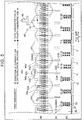
FIG. 3] FIG. 3 is a diagram showing a U-phase concentric coil placed in slots according to the first embodiment of the present invention. - [
FIG. 4] FIG. 4 is a partial enlarged view ofFIG. 3 , showing only a first concentric coil and a second concentric coil. - [
FIG. 5] FIG. 5 is a partial enlarged view ofFIG. 3 , showing only a third concentric coil and a fourth concentric coil. - [
FIG. 6] FIG. 6 is a partial enlarged view ofFIG. 3 . - [
FIG. 7] FIG. 7 is a partial enlarged view ofFIG. 3 , schematically illustrating how the first to fourth concentric coils are arranged. - [
FIG. 8] FIG. 8 is a diagram showing a U-phase concentric coil placed in slots according to the second embodiment of the present invention. - [
FIG. 9] FIG. 9 is a partial enlarged view ofFIG. 8 , showing only a first concentric coil and a second concentric coil. - [
FIG. 10] FIG. 10 is a partial enlarged view ofFIG. 8 , showing only a third concentric coil and a fourth concentric coil. - Embodiments of the present invention will be described below based on the drawings.
- The structure of a rotating
electrical machine 100 according to a first embodiment will be described with reference toFIGS. 1 to 7 . - As shown in
FIG. 1 , the rotatingelectrical machine 100 includes arotor core 10. Therotor core 10 has a plurality of (e.g., 16)permanent magnets 11 arranged therein in the circumferential direction. In the first embodiment, the plurality ofpermanent magnets 11 are arranged at substantially regular angular intervals (intervals of about 22.5 degrees) in the circumferential direction of therotor core 10. - The rotating
electrical machine 100 includes astator core 20. Thestator core 20 is placed so as to face therotor core 10 in the radial direction. Thestator core 20 has a plurality of (e.g., 96)slots 21. Thestator core 20 hasteeth 22 each located between adjacent ones of theslots 21. - The rotating
electrical machine 100 includes aconcentric coil 30 formed by concentrically winding a rectangular wire. Theconcentric coil 30 is placed in theslots 21 of thestator core 20. - As shown in
FIG. 4 , theconcentric coil 30 is a continuous coil comprised of a first slot accommodatedportion 30a that is accommodated in apredetermined slot 21 and a second slot accommodatedportion 30b that is accommodated in aslot 21 different from thepredetermined slot 21 with both a firstcoil end portion 30c and a secondcoil end portion 30d between the first slot accommodatedportion 30a and the second slot accommodatedportion 30b. The firstcoil end portion 30c is a coil end portion that forms a coil end located on one side in the axial direction, and the secondcoil end portion 30d is a coil end portion that forms a coil end located on the other side in the axial direction. Specifically, theconcentric coil 30 is a coil formed by continuously winding a single wire so as to form the first slot accommodatedportion 30a, the firstcoil end portion 30c, the second slot accommodatedportion 30b, and the secondcoil end portion 30d. - As shown in
FIG. 2 , theconcentric coil 30 includes a U-phaseconcentric coil 40, a V-phaseconcentric coil 50, and a W-phaseconcentric coil 60. The U-phaseconcentric coil 40 includes a firstconcentric coil 41 and a secondconcentric coil 42 which are of the same phase (U-phase) and are connected in series with each other, and a thirdconcentric coil 43 and a fourthconcentric coil 44 which are of the same phase (U-phase) and are connected in series with each other. The firstconcentric coil 41 and the secondconcentric coil 42 which are connected in series with each other are connected in parallel with the thirdconcentric coil 43 and the fourthconcentric coil 44 which are connected in series with each other. - The V-phase
concentric coil 50 includes a firstconcentric coil 51 and a secondconcentric coil 52 which are of the same phase (V-phase) and are connected in series with each other, and a thirdconcentric coil 53 and a fourthconcentric coil 54 which are of the same phase (V-phase) and are connected in series with each other. The firstconcentric coil 51 and the secondconcentric coil 52 which are connected in series with each other are connected in parallel with the thirdconcentric coil 53 and the fourthconcentric coil 54 which are connected in series with each other. - The W-phase
concentric coil 60 includes a firstconcentric coil 61 and a secondconcentric coil 62 which are of the same phase (W-phase) and are connected in series with each other, and a thirdconcentric coil 63 and a fourthconcentric coil 64 which are of the same phase (W-phase) and are connected in series with each other. The firstconcentric coil 61 and the secondconcentric coil 62 which are connected in series with each other are connected in parallel with the thirdconcentric coil 63 and the fourthconcentric coil 64 which are connected in series with each other. - In the first embodiment, the U-phase
concentric coil 40, the V-phaseconcentric coil 50, and the W-phaseconcentric coil 60 are connected in a Y configuration. - Since the U-phase
concentric coil 40, the V-phaseconcentric coil 50, and the W-phaseconcentric coil 60 are placed in theslots 21 in similar configurations, the U-phaseconcentric coil 40 will be described below. - The first to fourth
concentric coils 41 to 44 will be described with reference toFIGS. 3 to 6 .FIG. 4 shows only the U-phase firstconcentric coil 41 and the U-phase secondconcentric coil 42 of the U-phaseconcentric coil 40.FIG. 4(a) shows theslots 21 and the firstconcentric coil 41 and the secondconcentric coil 42 which are placed in theslots 21.FIG. 4(b) shows the centers (shown by long dashed double-short dashed lines) ofmagnetic poles 70 and the positions of coil centers (C11, C12) and connection centers (C21, C22) with respect to the centers (A1, A2) of themagnetic poles 70. The "connection center" is also the "center between two coil centers connected together."FIG. 4(c) shows the firstconcentric coil 41 and the secondconcentric coil 42 which are formed by a rectangular wire and placed in theslots 21.FIG. 4(c) also shows the positional relationship of thepermanent magnets 11 with theslots 21. The numbers shown on top of theslots 21 inFIG. 4(c) denote slot numbers.FIG. 5 shows only the U-phase thirdconcentric coil 43 and the U-phase fourthconcentric coil 44 of the U-phaseconcentric coil 40. - As shown in
FIG. 4 , the coil center (C11, C12) means a line segment extending in the axial direction and passing through the middle in the circumferential direction between the first slot accommodatedportion 30a that is accommodated in thepredetermined slot 21 and the second slot accommodatedportion 30b that is accommodated in theslot 21 different from thepredetermined slot 21 in theconcentric coil 30. In the present embodiment, since theconcentric coil 30 has a substantially hexagonal shape, bent parts of the firstcoil end portion 30c and the secondcoil end portion 30d correspond to the coil center. However, the present invention is not limited to this, and the coil center means a line segment extending in the axial direction and passing through the middle in the circumferential direction between the first slot accommodatedportion 30a that is accommodated in thepredetermined slot 21 and the second slot accommodatedportion 30b that is accommodated in theslot 21 different from thepredetermined slot 21. - In the first embodiment, as shown in
FIG. 4 , the coil center C11 of the firstconcentric coil 41 is located on one side (X1 direction side) in the circumferential direction with respect to the center A1 of the magnetic pole 70 (first magnetic pole 71). The coil center C12 of the secondconcentric coil 42 is located on the other side (X2 direction side) in the circumferential direction with respect to the center A1 of the firstmagnetic pole 71. As shown inFIG. 5 , the coil center C13 of the thirdconcentric coil 43 is located on the one side (X1 direction side) in the circumferential direction with respect to the center A2 of a secondmagnetic pole 72. The coil center C14 of the fourthconcentric coil 44 is located on the other side (X2 direction side) in the circumferential direction with respect to the center A2 of the secondmagnetic pole 72. - Specifically, as shown in
FIG. 4 , the coil center C11 of the firstconcentric coil 41 is located at a position shifted by approximately 1/2 of the slot width toward the one side (X1 direction side) in the circumferential direction with respect to the center A1 of the firstmagnetic pole 71, and the coil center C12 of the secondconcentric coil 42 is located at a position shifted by approximately 1/2 of the slot width toward the other side (X2 direction side) in the circumferential direction with respect to the center A1 of the firstmagnetic pole 71. For example, the firstconcentric coil 41 is placed in theslot 21 ofslot number 24 and theslot 21 ofslot number 18. That is, the pitch of the firstconcentric coil 41 is 6 slots. The secondconcentric coil 42 is placed in theslot 21 ofslot number 25 and theslot 21 ofslot number 19. That is, the pitch of the secondconcentric coil 42 is 6 slots. - The centers of the magnetic poles will be described. As shown in
FIG. 4 , a firstconcentric coil 301 and a secondconcentric coil 302 areconcentric coils 30 that are of the same phase out of a plurality of phases (e.g., in the case of a three-phase configuration, three phases, namely U-phase, V-phase, and W-phase) formed by differentconcentric coils 30 and that are located next to each other in the circumferential direction. The firstconcentric coil 301 and the secondconcentric coil 302 have first slot accommodatedportions 30a that are accommodated in adjacent ones of theslots 21 and second slot accommodatedportions 30b that are accommodated in adjacent ones of theslots 21 which are separated by a predetermined interval in the circumferential direction from theslots 21 of the first slot accommodatedportions 30a. In each of the firstconcentric coil 301 and the secondconcentric coil 302, the same wire is continuously wound to form the first slot accommodatedportion 30a and the second slot accommodatedportion 30b. The center (A1) of the magnetic pole means a line segment extending in the axial direction and passing through the middle in the circumferential direction between the coil centers of theconcentric coil 301 and the secondconcentric coil 302 which are of the same phase and are located next to each other in the circumferential direction. The firstconcentric coil 301 is connected via aconnection portion 41b to a firstconcentric coil 303 of the same phase which is accommodated inslots 21 separated in the circumferential direction from theslots 21 of the firstconcentric coil 301, and the center (A2) of the magnetic pole means a line segment extending in the axial direction and passing through the middle in the circumferential direction between the centers of these concentric coils including theconnection portion 41b. - As shown in
FIG. 5 , the coil center C13 of the thirdconcentric coil 43 is located at a position shifted by approximately 1/2 of the slot width toward the one side (X1 direction side) in the circumferential direction with respect to the center A2 of the secondmagnetic pole 72 adjacent to the firstmagnetic pole 71, and the coil center C14 of the fourthconcentric coil 44 is located at a position shifted by approximately 1/2 of the slot width toward the other side (X2 direction side) in the circumferential direction with respect to the center A2 of the secondmagnetic pole 72. For example, the thirdconcentric coil 43 is placed in theslot 21 ofslot number 18 and theslot 21 ofslot number 12. That is, the pitch of the thirdconcentric coil 43 is 6 slots. The fourthconcentric coil 44 is placed in theslot 21 ofslot number 19 and theslot 21 ofslot number 13. That is, the pitch of the fourthconcentric coil 44 is 6 slots. - The rotating
electrical machine 100 thus has the firstconcentric coil 41 and the thirdconcentric coil 43 in oneslot 21 and has the secondconcentric coil 42 and the fourthconcentric coil 44 in oneslot 21. - In the first embodiment, as shown in
FIG. 4 , the firstconcentric coil 41 includes a plurality ofcoil portions 41a formed by concentrically winding a rectangular wire, andconnection portions 41b each connecting thecoil portions 41a. The connection center C21 in theconnection portion 41b is located at a position shifted by approximately 1/2 of the slot width toward the one side (X1 direction side) in the circumferential direction with respect to the center A2 of the secondmagnetic pole 72. For example, theconnection portion 41b is placed so as to extend in the circumferential direction from theslot 21 ofslot number 18 to theslot 21 ofslot number 12. That is, the pitch of theconnection portion 41b is 6 slots. - The second
concentric coil 42 includes a plurality ofcoil portions 42a formed by concentrically winding a rectangular wire, andconnection portions 42b each connecting thecoil portions 42a. The connection center C22 in theconnection portion 42b is located at a position shifted by approximately 1/2 of the slot width toward the other side (X2 direction side) in the circumferential direction with respect to the center A2 of the secondmagnetic pole 72. For example, theconnection portion 42b is placed so as to extend in the circumferential direction from theslot 21 ofslot number 19 to theslot 21 ofslot number 13. That is, the pitch of theconnection portion 42b is 6 slots. - As shown in
FIG. 5 , the thirdconcentric coil 43 includes a plurality ofcoil portions 43a formed by concentrically winding a rectangular wire, andconnection portions 43b each connecting thecoil portions 43a. The connection center C23 in theconnection portion 43b is located at a position shifted by approximately 1/2 of the slot width toward the one side (X1 direction side) in the circumferential direction with respect to the center A1 of the firstmagnetic pole 71. For example, theconnection portion 43b is placed so as to extend in the circumferential direction from theslot 21 ofslot number 24 to theslot 21 ofslot number 18. That is, the pitch of theconnection portion 43b is 6 slots. - The fourth
concentric coil 44 includes a plurality ofcoil portions 44a formed by concentrically winding a rectangular wire, andconnection portions 44b each connecting thecoil portions 44a. The connection center C24 in theconnection portion 44b is located at a position shifted by approximately 1/2 of the slot width toward the other side (X2 direction side) in the circumferential direction with respect to the center A1 of the firstmagnetic pole 71. For example, theconnection portion 44b is placed so as to extend in the circumferential direction from theslot 21 ofslot number 25 to theslot 21 ofslot number 19. That is, the pitch of theconnection portion 44b is 6 slots. - In the first embodiment, as shown in
FIGS. 4 and5 , a plurality ofsets 41c (42c, 43c, 44c) of thecoil portion 41a (42a, 43a, 44a) and theconnection portion 41b (42b, 43b, 44b) are arranged in the circumferential direction. - As shown in
FIGS. 4 and6 , the firstconcentric coil 41 placed in theslot 21 of slot number 84 and the secondconcentric coil 42 placed in theslot 21 ofslot number 91 are connected in series with each other. As shown inFIGS. 5 and6 , the thirdconcentric coil 43 placed in theslot 21 ofslot number 96 and the fourthconcentric coil 44 placed in theslot 21 ofslot number 91 are connected in series with each other. - As shown in
FIGS. 4 to 6 , the firstconcentric coil 41 placed in theslot 21 of slot number 90 (a portion corresponding to theconnection portion 41b) and the thirdconcentric coil 43 placed in theslot 21 of slot number 90 (a portion corresponding to theconnection portion 43b) are connected to apower line 45. The secondconcentric coil 42 placed in theslot 21 of slot number 85 (a portion corresponding to theconnection portion 42b) and the fourthconcentric coil 44 placed in theslot 21 of slot number 1 (a portion corresponding to theconnection portion 44b) are connected to aneutral line 46. The firstconcentric coil 41 and the thirdconcentric coil 43 may be connected to theneutral line 46, and the secondconcentric coil 42 and the fourthconcentric coil 44 may be connected to thepower line 45. - The V-phase
concentric coil 50 and the W-phaseconcentric coil 60 have a structure similar to that of the U-phaseconcentric coil 40. That is, in the first embodiment, each of the coil centers of the firstconcentric coil 51 and the thirdconcentric coil 53 of the V-phaseconcentric coil 50 is located on the one side in the circumferential direction with respect to the center of themagnetic pole 70, and each of the coil centers of the secondconcentric coil 52 and the fourthconcentric coil 54 of the V-phaseconcentric coil 50 is located on the other side in the circumferential direction with respect to the center of themagnetic pole 70. Each of the coil centers of the firstconcentric coil 61 and the thirdconcentric coil 63 of the W-phaseconcentric coil 60 is located on the one side in the circumferential direction with respect to the center of themagnetic pole 70, and each of the coil centers of the secondconcentric coil 62 and the fourthconcentric coil 64 of the W-phaseconcentric coil 60 is located on the other side in the circumferential direction with respect to the center of themagnetic pole 70. - The first embodiment has the following effects. Although effects of the U-phase
concentric coil 40 are described below, the V-phaseconcentric coil 50 and the W-phaseconcentric coil 60 also have effects similar to those of the U-phaseconcentric coil 40. - In the first embodiment, of the first
concentric coil 41 and the secondconcentric coil 42 which are connected in series with each other and the thirdconcentric coil 43 and the fourthconcentric coil 44 which are connected in series with each other, each of the coil centers C11, C13 of the firstconcentric coil 41 and the thirdconcentric coil 43 is located on the one side in the circumferential direction with respect to the center of themagnetic pole 70, and each of the coil centers C12, C14 of the secondconcentric coil 42 and the fourthconcentric coil 44 is located on the other side in the circumferential direction with respect to the center of themagnetic pole 70, as described above. This prevents the firstconcentric coil 41 and the secondconcentric coil 42 which are connected in series with each other (the thirdconcentric coil 43 and the fourthconcentric coil 44 which are connected in series with each other) from being unevenly placed only on the one side or the other side in the circumferential direction with respect to the centers of themagnetic poles 70, and thus can eliminate an imbalance in the positional relationship between eachpermanent magnet 11 and theconcentric coil 40. As a result, generation of noise and vibration due to a circulating current in theconcentric coil 40 can be reduced in the rotatingelectrical machine 100 including theconcentric coil 40 formed by concentrically winding a rectangular wire. Adverse effects on torque of the rotatingelectrical machine 100 due to the circulating current in theconcentric coil 40 can also be reduced. - In the first embodiment, as described above, each of the first
concentric coil 41, the secondconcentric coil 42, the thirdconcentric coil 43, and the fourthconcentric coil 44 includes the plurality ofcoil portions connection portions coil portions connection portion 41b of the first concentric coil 41 (theconnection portion 43b of the third concentric coil 43) is located on the one side in the circumferential direction with respect to the center A1 of the firstmagnetic pole 71. The connection center C22 (C24) in theconnection portion 42b of the second concentric coil 42 (theconnection portion 44b of the fourth concentric coil 44) is located on the one side in the circumferential direction with respect to the center A1 of the firstmagnetic pole 71. Accordingly, the center of the coil portions of a set of the firstconcentric coil 41 and the secondconcentric coil 42 and the connection center of a set of theconnection portion 41b and theconnection portion 42b are located on the centers of themagnetic poles 70. Similarly, the center of the coil portions of a set of the thirdconcentric coil 43 and the fourthconcentric coil 44 and the connection center of a set of theconnection portion 43b and theconnection portion 44b are located on the centers of themagnetic poles 70. This prevents an imbalance in the positional relationship between eachpermanent magnet 11 and the first to fourthconcentric coils 41 to 44 and theconnection portions 41b to 44b. - In the first embodiment, as described above, the plurality of
sets 41c (42c, 43c, 44c) of thecoil portion 41a (42a, 43a, 44a) and theconnection portion 41b (42b, 43b, 44b) are arranged in the circumferential direction. This can eliminate an imbalance in the positional relationship between eachpermanent magnet 11 and theconcentric coil 40 along the entire circumference. - In the first embodiment, as described above, the coil center C11 of the first
concentric coil 41 is located on the one side in the circumferential direction with respect to the center A1 of the firstmagnetic pole 71, and the coil center C12 of the secondconcentric coil 42 is located on the other side in the circumferential direction with respect to the center A1 of the firstmagnetic pole 71. The coil center C13 of the thirdconcentric coil 43 is located on the one side in the circumferential direction with respect to the center A2 of the secondmagnetic pole 72 adjacent to the firstmagnetic pole 71, and the coil center C14 of the fourthconcentric coil 44 is located on the other side in the circumferential direction with respect to the center A2 of the secondmagnetic pole 72. Accordingly, the coil center of the set of the firstconcentric coil 41 and the secondconcentric coil 42 and the coil center of the set of the thirdconcentric coil 43 and the fourthconcentric coil 44 are located on the centers of themagnetic poles 70, whereby the balanced positional relationship between eachpermanent magnet 11 and each set can be maintained. - In the first embodiment, as described above, the plurality of
permanent magnets 11 are arranged at substantially regular angular intervals in the circumferential direction of therotor core 10. This prevents the positional relationship between thepermanent magnet 11 and theconcentric coil 40 to vary frompermanent magnet 11 topermanent magnet 11, and can thus eliminate an imbalance in the positional relationship between each of the plurality ofpermanent magnets 11 and theconcentric coil 40. - In the first embodiment, as described above, the
concentric coil 30 includes the three-phaseconcentric coils concentric coils magnetic pole 70, and each of the coil centers of the second concentric coil 42 (52, 62) and the fourth concentric coil 44 (54, 64) is located on the other side in the circumferential direction with respect to the center of themagnetic pole 70. This can eliminate an imbalance in the positional relationship between eachpermanent magnet 11 and theconcentric coil concentric coils - In the first embodiment, as described above, the three-phase
concentric coils permanent magnet 11 and theconcentric coil concentric coils - The structure of a rotating
electrical machine 200 according to a second embodiment will be described with reference toFIGS. 2 and8 to 10 . Unlike the first embodiment in which the firstconcentric coil 41 and the secondconcentric coil 42 whose coil centers C11, C12 are located on one side and the other side of the same firstmagnetic pole 71 are connected in series with each other, in the rotatingelectrical machine 200 of the second embodiment, a firstconcentric coil 141 whose coil center C31 is located on one side of the firstmagnetic pole 71 and a secondconcentric coil 142 whose coil center C32 is located on the other side of the secondmagnetic pole 72 adjacent to the firstmagnetic pole 71 are connected in series with each other. - In the second embodiment, as shown in
FIG. 2 , a U-phaseconcentric coil 140, a V-phaseconcentric coil 150, and a W-phaseconcentric coil 160 are connected in a Y-configuration. Since the U-phaseconcentric coil 140, the V-phaseconcentric coil 150, and a W-phaseconcentric coil 160 are placed in theslots 21 in similar configurations, the U-phaseconcentric coil 140 will be described below. - As shown in
FIGS. 8 and9 , the coil center C31 of the firstconcentric coil 141 of the U-phaseconcentric coil 140 is located on one side (X1 direction side) in the circumferential direction with respect to the center A1 of the firstmagnetic pole 71. The coil center C32 of the secondconcentric coil 142 is located on the other side (X2 direction side) in the circumferential direction with respect to the center A2 of the secondmagnetic pole 72 adjacent to the firstmagnetic pole 71. - As shown in
FIG. 10 , the coil center C33 of a thirdconcentric coil 143 is located on the one side in the circumferential direction with respect to the center A2 of the secondmagnetic pole 72, and the coil center C34 of a fourthconcentric coil 144 is located on the other side in the circumferential direction with respect to the center of the firstmagnetic pole 71. - The first
concentric coil 141 placed in theslot 21 of slot number 84 and the secondconcentric coil 142 placed in theslot 21 ofslot number 91 are connected in series with each other. The thirdconcentric coil 143 placed in theslot 21 ofslot number 96 and the fourthconcentric coil 144 placed in theslot 21 ofslot number 91 are connected in series with each other. - That is, in the second embodiment, the first concentric coil 41 (see
FIG. 7 ) and the fourthconcentric coil 44 of the first embodiment are connected in series with each other, and the secondconcentric coil 42 and the thirdconcentric coil 43 of the first embodiment are connected in series with each other. - The configuration of the second embodiment is otherwise similar to that of the first embodiment.
- The second embodiment has the following effects. Although effects of the U-phase
concentric coil 140 are described below, the V-phaseconcentric coil 150 and the W-phaseconcentric coil 160 also have effects similar to those of the U-phaseconcentric coil 140. - In the second embodiment, as described above, the coil center C31 of the first
concentric coil 141 is located on the one side in the circumferential direction with respect to the center A1 of the firstmagnetic pole 71, and the coil center C32 of the secondconcentric coil 142 is located on the other side in the circumferential direction with respect to the center A2 of the secondmagnetic pole 72 adjacent to the firstmagnetic pole 71. The coil center C33 of the thirdconcentric coil 143 is located on the one side in the circumferential direction with respect to the center A2 of the secondmagnetic pole 72, and the coil center C34 of the fourthconcentric coil 144 is located on the other side in the circumferential direction with respect to the center A1 of the firstmagnetic pole 71. Even in the configuration of the second embodiment different from the first embodiment, the center of the set of the firstconcentric coil 141 and the secondconcentric coil 142 and the coil center of the set of the thirdconcentric coil 143 and the fourthconcentric coil 144 are located on the centers of themagnetic poles 70, whereby the balanced positional relationship between eachpermanent magnet 11 and each set can be maintained. - Other effects of the second embodiment are similar to those of the first embodiment.
- The embodiments disclosed herein are by way of example in all respects and should not be interpreted as restrictive. The scope of the present invention is defined by the claims rather than by the description of the above embodiments, and includes all changes (modifications) that fall within the scope of the claims and the meaning and scope of equivalence.
- For example, the first and second embodiments are described with respect to the examples in which each of the coil centers of the first concentric coil and the third concentric coil is located at a position shifted by approximately 1/2 of the slot width to the one side with respect to the center of a magnetic pole and each of the coil centers of the third concentric coil and the fourth concentric coil is located at a position shifted by approximately 1/2 of the slot width to the other side with respect to the center of a magnetic pole. However, the present invention is not limited to this. In the present invention, each of the first to fourth concentric coils may be located at a position shifted by a distance other than approximately 1/2 of the slot width to the one side or the other side with respect to the center of a magnetic pole.
- The first and second embodiments are described with respect to the examples in which the stator core has 96 slots. However, the present invention is not limited to this. In the present invention, the number of slots may be other than 96.
- The first and second embodiments are described with respect to the examples in which the pitch of the first to fourth concentric coils is 6 slots. However, the present invention is not limited to this. In the present invention, the pitch of the first to fourth concentric coils may be other than 6 slots.
- The first and second embodiments are described with respect to the examples in which the pitch of the connection portion in the first to fourth concentric coils is 6 slots. However, the present invention is not limited to this. In the present invention, the pitch of the connection portion in the first to fourth concentric coils may be other than 6 slots.
- The first and second embodiments are described with respect to the examples in which the concentric coil includes the three-phase concentric coils. However, the present invention is not limited to this. In the present invention, the concentric coil may include concentric coils of the number of phases other than three.
- The first and second embodiments are described with respect to the examples in which the three-phase concentric coils are connected in a Y-configuration. However, the present invention is not limited to this. In the present invention, the three-phase concentric coils may be connected in a Δ-configuration.
-
- 10
- Rotor Core
- 11
- Permanent Magnet
- 20
- Stator Core
- 21
- Slot
- 30, 40, 50, 60, 140, 150, 160
- Concentric Coil
- 41, 51, 61, 141
- First Concentric Coil
- 42, 52, 62, 142
- Second Concentric Coil
- 43, 53, 63, 143
- Third Concentric Coil
- 44, 54, 64, 144
- Fourth Concentric Coil
- 41a, 42a, 43a, 44a
- Coil Portion
- 41b, 42b, 43b, 44b
- Connection Portion
- 41c, 42c, 43c, 44c
- Set
- 70
- Magnetic Pole
- 71
- First Magnetic Pole
- 72
- Second Magnetic Pole
- 100,200
- Rotating Electrical Machine
- A1
- Center (of First Magnetic Pole)
- A2
- Center (of Second Magnetic Pole)
- C11, C12, C13, C14, C31, C32, C33, C34
- Coil Center
- C21, C22, C23, C24
- Connection Center
Claims (8)
- A rotating electrical machine, comprising:a rotor core having a permanent magnet placed therein;a stator core placed so as to face the rotor core in a radial direction and having a plurality of slots; anda concentric coil formed by concentrically winding a wire and placed in the slots of the stator core, whereinthe concentric coil includes a first concentric coil and a second concentric coil which are of the same phase and are connected in series with each other, and a third concentric coil and a fourth concentric coil which are of the same phase and are connected in series with each other,the first concentric coil and the second concentric coil are connected in parallel with the third concentric coil and the fourth concentric coil, andeach of coil centers of the first concentric coil and the third concentric coil is located on one side in a circumferential direction with respect to a center of a magnetic pole, and each of coil centers of the second concentric coil and the fourth concentric coil is located on the other side in the circumferential direction with respect to the center of the magnetic pole.
- The rotating electrical machine according to claim 1, wherein
each of the first concentric coil, the second concentric coil, the third concentric coil, and the fourth concentric coil has a plurality of coil portions formed by concentrically winding a wire, and a connection portion connecting the coil portions,
a connection center in the connection portion of each of the first and third concentric coils is located on the one side in the circumferential direction with respect to the center of the magnetic pole, and
a connection center in the connection portion of each of the second and fourth concentric coils is located on the other side in the circumferential direction with respect to the center of the magnetic pole. - The rotating electrical machine according to claim 2, wherein
a plurality of sets of the coil portion and the connection portion are arranged in the circumferential direction. - The rotating electrical machine according to any one of claims 1 to 3, wherein
the coil center of the first concentric coil is located on one side in the circumferential direction with respect to a center of a first magnetic pole, and the coil center of the second concentric coil is located on the other side in the circumferential direction with respect to the center of the first magnetic pole, and
the coil center of the third concentric coil is located on one side in the circumferential direction with respect to a center of a second magnetic pole adjacent to the first magnetic pole, and the coil center of the fourth concentric coil is located on the other side in the circumferential direction with respect to the center of the second magnetic pole. - The rotating electrical machine according to any one of claims 1 to 3, wherein
the coil center of the first concentric coil is located on one side in the circumferential direction with respect to a center of a first magnetic pole, and the coil center of the second concentric coil is located on the other side in the circumferential direction with respect to a center of a second magnetic pole adjacent to the first magnetic pole, and
the coil center of the third concentric coil is located on one side in the circumferential direction with respect to the center of the second magnetic pole, and the coil center of the fourth concentric coil is located on the other side in the circumferential direction with respect to the center of the first magnetic pole. - The rotating electrical machine according to any one of claims 1 to 5, wherein
a plurality of the permanent magnets are arranged at substantially regular angular intervals in the circumferential direction of the rotor core. - The rotating electrical machine according to any one of claims 1 to 6, wherein
the concentric coil includes three-phase concentric coils,
each of the three-phase concentric coils includes the first concentric coil and the second concentric coil which are connected in series with each other, and the third concentric coil and the fourth concentric coil which are connected in series with each other,
the first concentric coil and the second concentric coil are connected in parallel with the third concentric coil and the fourth concentric coil, and
each of the coil centers of the first concentric coil and the third concentric coil is located on the one side in the circumferential direction with respect to the center of the magnetic pole, and each of the coil centers of the second concentric coil and the fourth concentric coil is located on the other side in the circumferential direction with respect to the center of the magnetic pole. - The rotating electrical machine according to any one of claims 1 to 7, wherein
the concentric coil includes three-phase concentric coils, and the three-phase concentric coils are connected in a Y-configuration.
Applications Claiming Priority (3)
| Application Number | Priority Date | Filing Date | Title |
|---|---|---|---|
| JP2015060426 | 2015-03-24 | ||
| JP2015065597 | 2015-03-27 | ||
| PCT/JP2016/059468 WO2016153002A1 (en) | 2015-03-24 | 2016-03-24 | Rotating electrical machine |
Publications (4)
| Publication Number | Publication Date |
|---|---|
| EP3217516A1 true EP3217516A1 (en) | 2017-09-13 |
| EP3217516A4 EP3217516A4 (en) | 2018-01-24 |
| EP3217516B1 EP3217516B1 (en) | 2020-09-16 |
| EP3217516B8 EP3217516B8 (en) | 2020-11-04 |
Family
ID=56977443
Family Applications (2)
| Application Number | Title | Priority Date | Filing Date |
|---|---|---|---|
| EP16768905.8A Active EP3217516B8 (en) | 2015-03-24 | 2016-03-24 | Rotating electrical machine |
| EP16768904.1A Active EP3214733B1 (en) | 2015-03-24 | 2016-03-24 | Rotating electrical machine |
Family Applications After (1)
| Application Number | Title | Priority Date | Filing Date |
|---|---|---|---|
| EP16768904.1A Active EP3214733B1 (en) | 2015-03-24 | 2016-03-24 | Rotating electrical machine |
Country Status (6)
| Country | Link |
|---|---|
| US (2) | US10651700B2 (en) |
| EP (2) | EP3217516B8 (en) |
| JP (2) | JP6288370B2 (en) |
| KR (2) | KR101827235B1 (en) |
| CN (2) | CN107408856B (en) |
| WO (2) | WO2016153001A1 (en) |
Families Citing this family (11)
| Publication number | Priority date | Publication date | Assignee | Title |
|---|---|---|---|---|
| KR101920174B1 (en) * | 2015-07-23 | 2018-11-19 | 아이신에이더블류 가부시키가이샤 | Manufacturing method of stator and stator |
| KR102604381B1 (en) * | 2016-07-07 | 2023-11-21 | 엘지이노텍 주식회사 | Stator Unit, Stator and Motor having the same |
| JP6669624B2 (en) * | 2016-09-28 | 2020-03-18 | アイシン・エィ・ダブリュ株式会社 | Rotating electric machine |
| DE102017128827A1 (en) * | 2017-12-05 | 2019-06-06 | Ebm-Papst Mulfingen Gmbh & Co. Kg | Multi-tooth coil winding for a 2-phase induction machine |
| WO2019116918A1 (en) | 2017-12-14 | 2019-06-20 | アイシン・エィ・ダブリュ株式会社 | Stator |
| FR3078207B1 (en) * | 2018-02-16 | 2021-10-29 | Ifp Energies Now | STATOR OF AN ELECTRIC MACHINE WITH DOUBLE INSERTION OF WINDINGS IN THE NOTCHES |
| CN110556938B (en) * | 2018-05-31 | 2022-01-07 | 比亚迪股份有限公司 | Stator assembly and motor |
| CN110556935B (en) * | 2018-05-31 | 2022-01-07 | 比亚迪股份有限公司 | Stator assembly and motor |
| CN110556936B (en) * | 2018-05-31 | 2022-01-07 | 比亚迪股份有限公司 | Stator assembly and motor |
| JP7128702B2 (en) * | 2018-09-25 | 2022-08-31 | 株式会社Soken | Rotating electric machine |
| JP6824371B1 (en) * | 2019-12-04 | 2021-02-03 | 三菱電機株式会社 | Rotating machine |
Family Cites Families (8)
| Publication number | Priority date | Publication date | Assignee | Title |
|---|---|---|---|---|
| JP2001238388A (en) * | 2000-02-25 | 2001-08-31 | Hitachi Ltd | Armature winding of rotating electric machine, and rotating electric machine |
| JP4042676B2 (en) | 2003-10-20 | 2008-02-06 | 株式会社デンソー | Armature for rotating electrical machine |
| EP1653587B1 (en) * | 2004-10-29 | 2013-06-26 | Hitachi, Ltd. | Rotating electrical machine and manufacturing method thereof |
| US7923885B2 (en) | 2007-11-26 | 2011-04-12 | Denso Corporation | Stator for rotary electric machine, and rotary electric machine using the stator |
| JP5560176B2 (en) * | 2010-12-08 | 2014-07-23 | トヨタ自動車株式会社 | Motor and motor manufacturing method |
| US9444296B2 (en) * | 2012-04-19 | 2016-09-13 | Mitsubishi Electric Corporation | Stator winding of electrical rotating machine |
| JP5757282B2 (en) | 2012-11-07 | 2015-07-29 | 株式会社デンソー | Stator and rotating electric machine |
| JP6156268B2 (en) * | 2014-06-27 | 2017-07-05 | 株式会社デンソー | Rotating electric machine stator |
-
2016
- 2016-03-24 CN CN201680012240.0A patent/CN107408856B/en active Active
- 2016-03-24 WO PCT/JP2016/059467 patent/WO2016153001A1/en active Application Filing
- 2016-03-24 JP JP2017508439A patent/JP6288370B2/en active Active
- 2016-03-24 EP EP16768905.8A patent/EP3217516B8/en active Active
- 2016-03-24 US US15/545,986 patent/US10651700B2/en active Active
- 2016-03-24 KR KR1020177020208A patent/KR101827235B1/en active IP Right Grant
- 2016-03-24 US US15/544,396 patent/US10666104B2/en active Active
- 2016-03-24 WO PCT/JP2016/059468 patent/WO2016153002A1/en active Application Filing
- 2016-03-24 JP JP2017508438A patent/JP6288369B2/en active Active
- 2016-03-24 CN CN201680011936.1A patent/CN107408855B/en active Active
- 2016-03-24 EP EP16768904.1A patent/EP3214733B1/en active Active
- 2016-03-24 KR KR1020177019477A patent/KR101827690B1/en active IP Right Grant
Also Published As
| Publication number | Publication date |
|---|---|
| EP3217516B8 (en) | 2020-11-04 |
| EP3217516B1 (en) | 2020-09-16 |
| CN107408855B (en) | 2019-09-10 |
| KR101827690B1 (en) | 2018-02-08 |
| EP3214733A4 (en) | 2018-01-24 |
| US10651700B2 (en) | 2020-05-12 |
| KR20170096140A (en) | 2017-08-23 |
| EP3214733B1 (en) | 2019-08-28 |
| WO2016153001A1 (en) | 2016-09-29 |
| WO2016153002A1 (en) | 2016-09-29 |
| JPWO2016153001A1 (en) | 2017-09-14 |
| KR101827235B1 (en) | 2018-02-07 |
| JP6288369B2 (en) | 2018-03-07 |
| US20180269741A1 (en) | 2018-09-20 |
| US20180026487A1 (en) | 2018-01-25 |
| JP6288370B2 (en) | 2018-03-07 |
| JPWO2016153002A1 (en) | 2017-09-21 |
| CN107408855A (en) | 2017-11-28 |
| KR20170097742A (en) | 2017-08-28 |
| CN107408856B (en) | 2019-10-01 |
| CN107408856A (en) | 2017-11-28 |
| US10666104B2 (en) | 2020-05-26 |
| EP3217516A4 (en) | 2018-01-24 |
| EP3214733A1 (en) | 2017-09-06 |
Similar Documents
| Publication | Publication Date | Title |
|---|---|---|
| EP3217516B1 (en) | Rotating electrical machine | |
| US10305339B2 (en) | Rotating electrical machine and method of manufacturing the same | |
| US10873226B2 (en) | Rotary electric machine | |
| US9793772B2 (en) | Stator for rotating electric machine | |
| US11509180B2 (en) | Stator | |
| JP2007507192A (en) | Rotating electric machine having induction rotor | |
| JP2013165566A (en) | Rotary electric machine and method of manufacturing stator used therefor | |
| JP2019201485A (en) | Rotary electric machine | |
| US10128712B2 (en) | Rotating electrical machine and method of manufacturing the same | |
| JP6585236B2 (en) | Rotating electric machine and method of manufacturing rotating electric machine | |
| JP5462311B2 (en) | Rotating electric machine | |
| JP6366912B2 (en) | Rotating electric machine | |
| JP2018125993A (en) | Rotary electric machine | |
| JP2015180146A (en) | Coil for rotary electric machine | |
| JP2015186292A (en) | Coil for rotary electric machine |
Legal Events
| Date | Code | Title | Description |
|---|---|---|---|
| STAA | Information on the status of an ep patent application or granted ep patent |
Free format text: STATUS: THE INTERNATIONAL PUBLICATION HAS BEEN MADE |
|
| PUAI | Public reference made under article 153(3) epc to a published international application that has entered the european phase |
Free format text: ORIGINAL CODE: 0009012 |
|
| STAA | Information on the status of an ep patent application or granted ep patent |
Free format text: STATUS: REQUEST FOR EXAMINATION WAS MADE |
|
| 17P | Request for examination filed |
Effective date: 20170609 |
|
| AK | Designated contracting states |
Kind code of ref document: A1 Designated state(s): AL AT BE BG CH CY CZ DE DK EE ES FI FR GB GR HR HU IE IS IT LI LT LU LV MC MK MT NL NO PL PT RO RS SE SI SK SM TR |
|
| AX | Request for extension of the european patent |
Extension state: BA ME |
|
| A4 | Supplementary search report drawn up and despatched |
Effective date: 20180104 |
|
| RIC1 | Information provided on ipc code assigned before grant |
Ipc: H02K 3/28 20060101ALI20171221BHEP Ipc: H02K 15/085 20060101ALI20171221BHEP Ipc: H02K 3/04 20060101AFI20171221BHEP |
|
| STAA | Information on the status of an ep patent application or granted ep patent |
Free format text: STATUS: EXAMINATION IS IN PROGRESS |
|
| 17Q | First examination report despatched |
Effective date: 20180129 |
|
| DAV | Request for validation of the european patent (deleted) | ||
| DAX | Request for extension of the european patent (deleted) | ||
| GRAP | Despatch of communication of intention to grant a patent |
Free format text: ORIGINAL CODE: EPIDOSNIGR1 |
|
| STAA | Information on the status of an ep patent application or granted ep patent |
Free format text: STATUS: GRANT OF PATENT IS INTENDED |
|
| RIN1 | Information on inventor provided before grant (corrected) |
Inventor name: KOGA, KIYOTAKA |
|
| INTG | Intention to grant announced |
Effective date: 20200424 |
|
| GRAS | Grant fee paid |
Free format text: ORIGINAL CODE: EPIDOSNIGR3 |
|
| GRAA | (expected) grant |
Free format text: ORIGINAL CODE: 0009210 |
|
| STAA | Information on the status of an ep patent application or granted ep patent |
Free format text: STATUS: THE PATENT HAS BEEN GRANTED |
|
| AK | Designated contracting states |
Kind code of ref document: B1 Designated state(s): AL AT BE BG CH CY CZ DE DK EE ES FI FR GB GR HR HU IE IS IT LI LT LU LV MC MK MT NL NO PL PT RO RS SE SI SK SM TR |
|
| REG | Reference to a national code |
Ref country code: GB Ref legal event code: FG4D |
|
| REG | Reference to a national code |
Ref country code: DE Ref legal event code: R081 Ref document number: 602016044158 Country of ref document: DE Owner name: AISIN AW CO., LTD., ANJO-SHI, JP Free format text: FORMER OWNER: AISIN AW CO., LTD., ANJO, AICHI, JP Ref country code: DE Ref legal event code: R082 Ref document number: 602016044158 Country of ref document: DE Representative=s name: KRAMER BARSKE SCHMIDTCHEN PATENTANWAELTE PARTG, DE |
|
| REG | Reference to a national code |
Ref country code: CH Ref legal event code: EP |
|
| RAP2 | Party data changed (patent owner data changed or rights of a patent transferred) |
Owner name: AISIN AW CO., LTD. |
|
| REG | Reference to a national code |
Ref country code: DE Ref legal event code: R096 Ref document number: 602016044158 Country of ref document: DE |
|
| REG | Reference to a national code |
Ref country code: IE Ref legal event code: FG4D |
|
| REG | Reference to a national code |
Ref country code: CH Ref legal event code: PK Free format text: BERICHTIGUNG B8 Ref country code: AT Ref legal event code: REF Ref document number: 1315030 Country of ref document: AT Kind code of ref document: T Effective date: 20201015 |
|
| PG25 | Lapsed in a contracting state [announced via postgrant information from national office to epo] |
Ref country code: GR Free format text: LAPSE BECAUSE OF FAILURE TO SUBMIT A TRANSLATION OF THE DESCRIPTION OR TO PAY THE FEE WITHIN THE PRESCRIBED TIME-LIMIT Effective date: 20201217 Ref country code: SE Free format text: LAPSE BECAUSE OF FAILURE TO SUBMIT A TRANSLATION OF THE DESCRIPTION OR TO PAY THE FEE WITHIN THE PRESCRIBED TIME-LIMIT Effective date: 20200916 Ref country code: HR Free format text: LAPSE BECAUSE OF FAILURE TO SUBMIT A TRANSLATION OF THE DESCRIPTION OR TO PAY THE FEE WITHIN THE PRESCRIBED TIME-LIMIT Effective date: 20200916 Ref country code: FI Free format text: LAPSE BECAUSE OF FAILURE TO SUBMIT A TRANSLATION OF THE DESCRIPTION OR TO PAY THE FEE WITHIN THE PRESCRIBED TIME-LIMIT Effective date: 20200916 Ref country code: BG Free format text: LAPSE BECAUSE OF FAILURE TO SUBMIT A TRANSLATION OF THE DESCRIPTION OR TO PAY THE FEE WITHIN THE PRESCRIBED TIME-LIMIT Effective date: 20201216 Ref country code: NO Free format text: LAPSE BECAUSE OF FAILURE TO SUBMIT A TRANSLATION OF THE DESCRIPTION OR TO PAY THE FEE WITHIN THE PRESCRIBED TIME-LIMIT Effective date: 20201216 |
|
| REG | Reference to a national code |
Ref country code: AT Ref legal event code: MK05 Ref document number: 1315030 Country of ref document: AT Kind code of ref document: T Effective date: 20200916 |
|
| REG | Reference to a national code |
Ref country code: NL Ref legal event code: MP Effective date: 20200916 |
|
| PG25 | Lapsed in a contracting state [announced via postgrant information from national office to epo] |
Ref country code: RS Free format text: LAPSE BECAUSE OF FAILURE TO SUBMIT A TRANSLATION OF THE DESCRIPTION OR TO PAY THE FEE WITHIN THE PRESCRIBED TIME-LIMIT Effective date: 20200916 Ref country code: LV Free format text: LAPSE BECAUSE OF FAILURE TO SUBMIT A TRANSLATION OF THE DESCRIPTION OR TO PAY THE FEE WITHIN THE PRESCRIBED TIME-LIMIT Effective date: 20200916 |
|
| REG | Reference to a national code |
Ref country code: LT Ref legal event code: MG4D |
|
| PG25 | Lapsed in a contracting state [announced via postgrant information from national office to epo] |
Ref country code: SM Free format text: LAPSE BECAUSE OF FAILURE TO SUBMIT A TRANSLATION OF THE DESCRIPTION OR TO PAY THE FEE WITHIN THE PRESCRIBED TIME-LIMIT Effective date: 20200916 Ref country code: EE Free format text: LAPSE BECAUSE OF FAILURE TO SUBMIT A TRANSLATION OF THE DESCRIPTION OR TO PAY THE FEE WITHIN THE PRESCRIBED TIME-LIMIT Effective date: 20200916 Ref country code: LT Free format text: LAPSE BECAUSE OF FAILURE TO SUBMIT A TRANSLATION OF THE DESCRIPTION OR TO PAY THE FEE WITHIN THE PRESCRIBED TIME-LIMIT Effective date: 20200916 Ref country code: PT Free format text: LAPSE BECAUSE OF FAILURE TO SUBMIT A TRANSLATION OF THE DESCRIPTION OR TO PAY THE FEE WITHIN THE PRESCRIBED TIME-LIMIT Effective date: 20210118 Ref country code: RO Free format text: LAPSE BECAUSE OF FAILURE TO SUBMIT A TRANSLATION OF THE DESCRIPTION OR TO PAY THE FEE WITHIN THE PRESCRIBED TIME-LIMIT Effective date: 20200916 Ref country code: CZ Free format text: LAPSE BECAUSE OF FAILURE TO SUBMIT A TRANSLATION OF THE DESCRIPTION OR TO PAY THE FEE WITHIN THE PRESCRIBED TIME-LIMIT Effective date: 20200916 |
|
| PG25 | Lapsed in a contracting state [announced via postgrant information from national office to epo] |
Ref country code: IS Free format text: LAPSE BECAUSE OF FAILURE TO SUBMIT A TRANSLATION OF THE DESCRIPTION OR TO PAY THE FEE WITHIN THE PRESCRIBED TIME-LIMIT Effective date: 20210116 Ref country code: PL Free format text: LAPSE BECAUSE OF FAILURE TO SUBMIT A TRANSLATION OF THE DESCRIPTION OR TO PAY THE FEE WITHIN THE PRESCRIBED TIME-LIMIT Effective date: 20200916 Ref country code: AL Free format text: LAPSE BECAUSE OF FAILURE TO SUBMIT A TRANSLATION OF THE DESCRIPTION OR TO PAY THE FEE WITHIN THE PRESCRIBED TIME-LIMIT Effective date: 20200916 Ref country code: AT Free format text: LAPSE BECAUSE OF FAILURE TO SUBMIT A TRANSLATION OF THE DESCRIPTION OR TO PAY THE FEE WITHIN THE PRESCRIBED TIME-LIMIT Effective date: 20200916 Ref country code: ES Free format text: LAPSE BECAUSE OF FAILURE TO SUBMIT A TRANSLATION OF THE DESCRIPTION OR TO PAY THE FEE WITHIN THE PRESCRIBED TIME-LIMIT Effective date: 20200916 |
|
| REG | Reference to a national code |
Ref country code: DE Ref legal event code: R097 Ref document number: 602016044158 Country of ref document: DE |
|
| PG25 | Lapsed in a contracting state [announced via postgrant information from national office to epo] |
Ref country code: SK Free format text: LAPSE BECAUSE OF FAILURE TO SUBMIT A TRANSLATION OF THE DESCRIPTION OR TO PAY THE FEE WITHIN THE PRESCRIBED TIME-LIMIT Effective date: 20200916 |
|
| PLBE | No opposition filed within time limit |
Free format text: ORIGINAL CODE: 0009261 |
|
| STAA | Information on the status of an ep patent application or granted ep patent |
Free format text: STATUS: NO OPPOSITION FILED WITHIN TIME LIMIT |
|
| 26N | No opposition filed |
Effective date: 20210617 |
|
| PG25 | Lapsed in a contracting state [announced via postgrant information from national office to epo] |
Ref country code: DK Free format text: LAPSE BECAUSE OF FAILURE TO SUBMIT A TRANSLATION OF THE DESCRIPTION OR TO PAY THE FEE WITHIN THE PRESCRIBED TIME-LIMIT Effective date: 20200916 Ref country code: SI Free format text: LAPSE BECAUSE OF FAILURE TO SUBMIT A TRANSLATION OF THE DESCRIPTION OR TO PAY THE FEE WITHIN THE PRESCRIBED TIME-LIMIT Effective date: 20200916 |
|
| PG25 | Lapsed in a contracting state [announced via postgrant information from national office to epo] |
Ref country code: MC Free format text: LAPSE BECAUSE OF FAILURE TO SUBMIT A TRANSLATION OF THE DESCRIPTION OR TO PAY THE FEE WITHIN THE PRESCRIBED TIME-LIMIT Effective date: 20200916 Ref country code: IT Free format text: LAPSE BECAUSE OF FAILURE TO SUBMIT A TRANSLATION OF THE DESCRIPTION OR TO PAY THE FEE WITHIN THE PRESCRIBED TIME-LIMIT Effective date: 20200916 |
|
| REG | Reference to a national code |
Ref country code: CH Ref legal event code: PL |
|
| REG | Reference to a national code |
Ref country code: BE Ref legal event code: MM Effective date: 20210331 |
|
| PG25 | Lapsed in a contracting state [announced via postgrant information from national office to epo] |
Ref country code: IE Free format text: LAPSE BECAUSE OF NON-PAYMENT OF DUE FEES Effective date: 20210324 Ref country code: CH Free format text: LAPSE BECAUSE OF NON-PAYMENT OF DUE FEES Effective date: 20210331 Ref country code: LU Free format text: LAPSE BECAUSE OF NON-PAYMENT OF DUE FEES Effective date: 20210324 Ref country code: LI Free format text: LAPSE BECAUSE OF NON-PAYMENT OF DUE FEES Effective date: 20210331 |
|
| PG25 | Lapsed in a contracting state [announced via postgrant information from national office to epo] |
Ref country code: BE Free format text: LAPSE BECAUSE OF NON-PAYMENT OF DUE FEES Effective date: 20210331 |
|
| PGFP | Annual fee paid to national office [announced via postgrant information from national office to epo] |
Ref country code: FR Payment date: 20230208 Year of fee payment: 8 |
|
| PG25 | Lapsed in a contracting state [announced via postgrant information from national office to epo] |
Ref country code: HU Free format text: LAPSE BECAUSE OF FAILURE TO SUBMIT A TRANSLATION OF THE DESCRIPTION OR TO PAY THE FEE WITHIN THE PRESCRIBED TIME-LIMIT; INVALID AB INITIO Effective date: 20160324 |
|
| PGFP | Annual fee paid to national office [announced via postgrant information from national office to epo] |
Ref country code: GB Payment date: 20230202 Year of fee payment: 8 Ref country code: DE Payment date: 20230131 Year of fee payment: 8 |
|
| PG25 | Lapsed in a contracting state [announced via postgrant information from national office to epo] |
Ref country code: NL Free format text: LAPSE BECAUSE OF NON-PAYMENT OF DUE FEES Effective date: 20200923 Ref country code: CY Free format text: LAPSE BECAUSE OF FAILURE TO SUBMIT A TRANSLATION OF THE DESCRIPTION OR TO PAY THE FEE WITHIN THE PRESCRIBED TIME-LIMIT Effective date: 20200916 |