EP3217441A1 - Semiconductor light-emitting device - Google Patents
Semiconductor light-emitting device Download PDFInfo
- Publication number
- EP3217441A1 EP3217441A1 EP15858018.3A EP15858018A EP3217441A1 EP 3217441 A1 EP3217441 A1 EP 3217441A1 EP 15858018 A EP15858018 A EP 15858018A EP 3217441 A1 EP3217441 A1 EP 3217441A1
- Authority
- EP
- European Patent Office
- Prior art keywords
- layer
- light
- emitting
- base
- semiconductor
- Prior art date
- Legal status (The legal status is an assumption and is not a legal conclusion. Google has not performed a legal analysis and makes no representation as to the accuracy of the status listed.)
- Granted
Links
- 239000004065 semiconductor Substances 0.000 title claims abstract description 117
- 239000010410 layer Substances 0.000 claims abstract description 462
- 239000000203 mixture Substances 0.000 claims abstract description 51
- 230000004888 barrier function Effects 0.000 claims abstract description 27
- 239000002346 layers by function Substances 0.000 claims abstract description 27
- 229910002704 AlGaN Inorganic materials 0.000 claims abstract description 14
- 230000000694 effects Effects 0.000 claims description 3
- 239000000758 substrate Substances 0.000 description 22
- 230000000903 blocking effect Effects 0.000 description 11
- 230000003595 spectral effect Effects 0.000 description 9
- 238000009877 rendering Methods 0.000 description 7
- OAICVXFJPJFONN-UHFFFAOYSA-N Phosphorus Chemical compound [P] OAICVXFJPJFONN-UHFFFAOYSA-N 0.000 description 6
- 238000010030 laminating Methods 0.000 description 5
- 239000000463 material Substances 0.000 description 5
- 238000000034 method Methods 0.000 description 5
- 230000007423 decrease Effects 0.000 description 4
- 239000002019 doping agent Substances 0.000 description 4
- 238000006243 chemical reaction Methods 0.000 description 3
- 239000013078 crystal Substances 0.000 description 3
- 230000006798 recombination Effects 0.000 description 3
- 238000005215 recombination Methods 0.000 description 3
- 229910052594 sapphire Inorganic materials 0.000 description 3
- 239000010980 sapphire Substances 0.000 description 3
- 230000015572 biosynthetic process Effects 0.000 description 2
- 230000008859 change Effects 0.000 description 2
- 239000003086 colorant Substances 0.000 description 2
- 238000010586 diagram Methods 0.000 description 2
- 238000004519 manufacturing process Methods 0.000 description 2
- 239000002184 metal Substances 0.000 description 2
- 229910052751 metal Inorganic materials 0.000 description 2
- 239000011347 resin Substances 0.000 description 2
- 229920005989 resin Polymers 0.000 description 2
- 238000007789 sealing Methods 0.000 description 2
- 238000001228 spectrum Methods 0.000 description 2
- 229910016920 AlzGa1−z Inorganic materials 0.000 description 1
- IOVCWXUNBOPUCH-UHFFFAOYSA-M Nitrite anion Chemical compound [O-]N=O IOVCWXUNBOPUCH-UHFFFAOYSA-M 0.000 description 1
- 238000005229 chemical vapour deposition Methods 0.000 description 1
- 239000000470 constituent Substances 0.000 description 1
- 230000006866 deterioration Effects 0.000 description 1
- 238000009826 distribution Methods 0.000 description 1
- 238000000295 emission spectrum Methods 0.000 description 1
- 238000000605 extraction Methods 0.000 description 1
- 230000017525 heat dissipation Effects 0.000 description 1
- 238000003475 lamination Methods 0.000 description 1
- 230000000116 mitigating effect Effects 0.000 description 1
- 150000004767 nitrides Chemical class 0.000 description 1
- 239000002245 particle Substances 0.000 description 1
- 230000009467 reduction Effects 0.000 description 1
- 238000005204 segregation Methods 0.000 description 1
- ORFSSYGWXNGVFB-UHFFFAOYSA-N sodium 4-amino-6-[[4-[4-[(8-amino-1-hydroxy-5,7-disulfonaphthalen-2-yl)diazenyl]-3-methoxyphenyl]-2-methoxyphenyl]diazenyl]-5-hydroxynaphthalene-1,3-disulfonic acid Chemical group COC1=C(C=CC(=C1)C2=CC(=C(C=C2)N=NC3=C(C4=C(C=C3)C(=CC(=C4N)S(=O)(=O)O)S(=O)(=O)O)O)OC)N=NC5=C(C6=C(C=C5)C(=CC(=C6N)S(=O)(=O)O)S(=O)(=O)O)O.[Na+] ORFSSYGWXNGVFB-UHFFFAOYSA-N 0.000 description 1
Images


Classifications
-
- H—ELECTRICITY
- H01—ELECTRIC ELEMENTS
- H01L—SEMICONDUCTOR DEVICES NOT COVERED BY CLASS H10
- H01L33/00—Semiconductor devices with at least one potential-jump barrier or surface barrier specially adapted for light emission; Processes or apparatus specially adapted for the manufacture or treatment thereof or of parts thereof; Details thereof
- H01L33/02—Semiconductor devices with at least one potential-jump barrier or surface barrier specially adapted for light emission; Processes or apparatus specially adapted for the manufacture or treatment thereof or of parts thereof; Details thereof characterised by the semiconductor bodies
- H01L33/08—Semiconductor devices with at least one potential-jump barrier or surface barrier specially adapted for light emission; Processes or apparatus specially adapted for the manufacture or treatment thereof or of parts thereof; Details thereof characterised by the semiconductor bodies with a plurality of light emitting regions, e.g. laterally discontinuous light emitting layer or photoluminescent region integrated within the semiconductor body
-
- H—ELECTRICITY
- H01—ELECTRIC ELEMENTS
- H01L—SEMICONDUCTOR DEVICES NOT COVERED BY CLASS H10
- H01L33/00—Semiconductor devices with at least one potential-jump barrier or surface barrier specially adapted for light emission; Processes or apparatus specially adapted for the manufacture or treatment thereof or of parts thereof; Details thereof
- H01L33/0004—Devices characterised by their operation
- H01L33/002—Devices characterised by their operation having heterojunctions or graded gap
- H01L33/0025—Devices characterised by their operation having heterojunctions or graded gap comprising only AIIIBV compounds
-
- H—ELECTRICITY
- H01—ELECTRIC ELEMENTS
- H01L—SEMICONDUCTOR DEVICES NOT COVERED BY CLASS H10
- H01L33/00—Semiconductor devices with at least one potential-jump barrier or surface barrier specially adapted for light emission; Processes or apparatus specially adapted for the manufacture or treatment thereof or of parts thereof; Details thereof
- H01L33/02—Semiconductor devices with at least one potential-jump barrier or surface barrier specially adapted for light emission; Processes or apparatus specially adapted for the manufacture or treatment thereof or of parts thereof; Details thereof characterised by the semiconductor bodies
- H01L33/04—Semiconductor devices with at least one potential-jump barrier or surface barrier specially adapted for light emission; Processes or apparatus specially adapted for the manufacture or treatment thereof or of parts thereof; Details thereof characterised by the semiconductor bodies with a quantum effect structure or superlattice, e.g. tunnel junction
- H01L33/06—Semiconductor devices with at least one potential-jump barrier or surface barrier specially adapted for light emission; Processes or apparatus specially adapted for the manufacture or treatment thereof or of parts thereof; Details thereof characterised by the semiconductor bodies with a quantum effect structure or superlattice, e.g. tunnel junction within the light emitting region, e.g. quantum confinement structure or tunnel barrier
-
- H—ELECTRICITY
- H01—ELECTRIC ELEMENTS
- H01L—SEMICONDUCTOR DEVICES NOT COVERED BY CLASS H10
- H01L33/00—Semiconductor devices with at least one potential-jump barrier or surface barrier specially adapted for light emission; Processes or apparatus specially adapted for the manufacture or treatment thereof or of parts thereof; Details thereof
- H01L33/02—Semiconductor devices with at least one potential-jump barrier or surface barrier specially adapted for light emission; Processes or apparatus specially adapted for the manufacture or treatment thereof or of parts thereof; Details thereof characterised by the semiconductor bodies
- H01L33/12—Semiconductor devices with at least one potential-jump barrier or surface barrier specially adapted for light emission; Processes or apparatus specially adapted for the manufacture or treatment thereof or of parts thereof; Details thereof characterised by the semiconductor bodies with a stress relaxation structure, e.g. buffer layer
-
- H—ELECTRICITY
- H01—ELECTRIC ELEMENTS
- H01L—SEMICONDUCTOR DEVICES NOT COVERED BY CLASS H10
- H01L33/00—Semiconductor devices with at least one potential-jump barrier or surface barrier specially adapted for light emission; Processes or apparatus specially adapted for the manufacture or treatment thereof or of parts thereof; Details thereof
- H01L33/02—Semiconductor devices with at least one potential-jump barrier or surface barrier specially adapted for light emission; Processes or apparatus specially adapted for the manufacture or treatment thereof or of parts thereof; Details thereof characterised by the semiconductor bodies
- H01L33/20—Semiconductor devices with at least one potential-jump barrier or surface barrier specially adapted for light emission; Processes or apparatus specially adapted for the manufacture or treatment thereof or of parts thereof; Details thereof characterised by the semiconductor bodies with a particular shape, e.g. curved or truncated substrate
- H01L33/24—Semiconductor devices with at least one potential-jump barrier or surface barrier specially adapted for light emission; Processes or apparatus specially adapted for the manufacture or treatment thereof or of parts thereof; Details thereof characterised by the semiconductor bodies with a particular shape, e.g. curved or truncated substrate of the light emitting region, e.g. non-planar junction
-
- H—ELECTRICITY
- H01—ELECTRIC ELEMENTS
- H01L—SEMICONDUCTOR DEVICES NOT COVERED BY CLASS H10
- H01L33/00—Semiconductor devices with at least one potential-jump barrier or surface barrier specially adapted for light emission; Processes or apparatus specially adapted for the manufacture or treatment thereof or of parts thereof; Details thereof
- H01L33/02—Semiconductor devices with at least one potential-jump barrier or surface barrier specially adapted for light emission; Processes or apparatus specially adapted for the manufacture or treatment thereof or of parts thereof; Details thereof characterised by the semiconductor bodies
- H01L33/26—Materials of the light emitting region
- H01L33/30—Materials of the light emitting region containing only elements of group III and group V of the periodic system
- H01L33/32—Materials of the light emitting region containing only elements of group III and group V of the periodic system containing nitrogen
Abstract
Description
- The present invention relates to a semiconductor light-emitting element, such as a light-emitting diode
- A semiconductor light-emitting element is generally manufactured by growing, on a growth substrate, a semiconductor structure layer comprised of an n-type semiconductor layer, an active layer, and a p-type semiconductor layer and forming an n-electrode and a p-electrode that apply voltage to the n-type semiconductor layer and the p-type semiconductor layer, respectively.
- Patent Literature 1 discloses a white light-emitting diode in which red, green, and blue light-emitting diodes are laminated in this order so as to emit light in the same direction. Patent Literature 2 discloses a white light-emitting element including: a first light-emitting portion bonded to a conductive sub-mount substrate by a metal layer; and a second light-emitting portion formed on one region of the upper surface of the conductive sub-mount substrate. Patent Literature 3 discloses a semiconductor light-emitting element including a plurality of well layers composed of InGaN in which the In compositions of the respective well layers are different.
-
- Patent Literature 1: Japanese Patent Application Laid-Open No.
2011-249460 - Patent Literature 2: Japanese Patent Application Laid-Open No.
2006-339646 - Patent Literature 3: Japanese Patent Application Laid-Open No.
2004-179493 - Emission of light by a semiconductor light-emitting element is induced when binding (recombination) of an electron and a hole injected into the element through electrodes occurs in the active layer of the element. The wavelength of the light emitted from the active layer (i.e. light-emitting color) differs depending on the band gap of the semiconductor materials that make up the active layer. For example, a light-emitting element using a nitrite-based semiconductor emits blue light from its active layer.
- A light source is required to have color rendering properties for, for example, lighting applications. A light source with high color rendering properties is a type of light source that emits near natural light. To achieve high color rendering properties, it is preferable that light emitted from a light source have a wavelength that substantially covers the entire wavelength of the visible region. For example, light extracted from a light source with high color rendering properties is observed as white light.
- In this regard, as disclosed in the aforementioned patent literatures, various techniques of using a semiconductor light-emitting element to acquire white light have been proposed. In one example technique of manufacturing a light-emitting device, a wavelength conversion member, such as a phosphor, is mixed into a sealing resin to seal the element by the sealing resin. For example, in the case of a semiconductor light-emitting element using an active layer that emits blue light, a part of blue light from the active layer is converted into yellow light by a phosphor, and the two types of light are mixed and emitted to the outside. The emitted light as a whole is thus observed as white light. In another proposed technique, by laminating a plurality of active layers with different compositions, the light emission wavelength range is widened without using a phosphor.
- However, a light-emitting device manufactured using the aforementioned techniques has problems relating to the uniformity of the light-emitting wavelength within the device, the complexity of the manufacturing process, and light-emitting intensity. Possible reasons include: addition of a phosphor mixing step; change of the wavelength conversion efficiency of a phosphor over time; addition of a processing step of a semiconductor layer; and deterioration of crystallinity due to processing of a semiconductor layer.
- The present invention has been made in view of the aforementioned problems. An object of the present invention is to provide a semiconductor light-emitting element that does not require a wavelength conversion member, such as a phosphor, and that has a light-emitting wavelength band (spectral width) in a wide range of the visible region and has high color rendering properties and a high light-emitting intensity.
- A semiconductor light-emitting element according to the present invention includes: a first semiconductor layer of a first conductivity type; a light-emitting functional layer that is formed on the first semiconductor layer and includes a light-emitting layer; and a second semiconductor layer that is formed on the light-emitting functional layer and is of a conductivity type opposite to a conductivity type of the first semiconductor layer. The light-emitting layer has: a base layer which has a composition subject to stress strain from the first semiconductor layer and has a plurality of base segments formed in a random net shape; and a quantum well structure layer formed by embedding the base layer and composed of at least one quantum well layer and at least one barrier layer. The base layer has a plurality of sub-base layers composed of AlGaN with different Al compositions.
-
-
Fig. 1(a) is a cross-sectional view illustrating a structure of a semiconductor light-emitting element according to a first embodiment, andFig. 1(b) is a schematic top plan view of a base layer of a light-emitting layer. -
Fig. 2 is a cross-sectional view illustrating a structure of the light-emitting layer of the semiconductor light-emitting element according to the first embodiment. -
Fig. 3 is a cross-sectional view illustrating a structure of a light-emitting layer of a semiconductor light-emitting element according to a first modified example of the first embodiment. -
Fig. 4 is a cross-sectional view illustrating a structure of a semiconductor light-emitting element according to a second modified example of the first embodiment. -
Fig. 5 is a cross-sectional view illustrating a structure of a semiconductor light-emitting element according to a second embodiment -
Fig. 6 is a diagram illustrating an emission spectrum from the semiconductor light-emitting element according to the second embodiment. - Embodiments of the present invention will now be described in detail hereinbelow. In this specification, an identical reference numeral is assigned to identical constituent elements.
-
Fig. 1(a) is a cross-sectional view illustrating a structure of a semiconductor light-emitting element (hereinafter, simply referred to as "light-emitting element" or "element" in some cases) 10 according to a first embodiment. In the structure of the semiconductor light-emittingelement 10, a semiconductor structure layer SL is formed on a mounting substrate (hereinafter, simply referred to as "substrate" in some cases) 11. The semiconductor structure layer SL includes an n-type semiconductor layer (first semiconductor layer) 12 formed on themounting substrate 11, a light-emittingfunctional layer 13 formed on the n-type semiconductor layer 12, anelectron blocking layer 14 formed on the light-emittingfunctional layer 13, and a p-type semiconductor layer (second semiconductor layer, i.e. a semiconductor layer whose conductivity type is opposite to the conductivity type of the first semiconductor layer 12) 15 formed on theelectron blocking layer 14. - According to this embodiment, the
mounting substrate 11 is composed of a growth substrate used for growth of, for example, the semiconductor structure layer SL, and is made of sapphire, for example. In addition, the semiconductor structure layer SL is composed of a nitride-based semiconductor. The semiconductor light-emitting element 10 can be manufactured by growing the semiconductor structure layer SL on the sapphire substrate, for example, whose c-plane serves as a crystal growth surface, using the Metal Organic Chemical Vapor Deposition (MOCVD) method. Although not illustrated in the drawings, the light-emittingelement 10 has an n-electrode and a p-electrode that apply voltage to the n-type semiconductor layer 12 and the p-type semiconductor layer 15, respectively. - This embodiment is illustrated with reference to the structure of the light-emitting
element 10 where the semiconductor structure layer SL is formed on a growth substrate serving as themounting substrate 11. However, it is not limited to the structure where themounting substrate 11 is the growth substrate. For example, the semiconductor light-emitting element 10 may have a structure obtained by first growing the semiconductor structure layer SL on a growth substrate, bonding the semiconductor structure layer SL to another substrate, and removing the growth substrate. In this case, the other substrate thus bonded is formed on the p-type semiconductor layer 15. The aforementioned pasted substrate may use materials with a high degree of heat dissipation, such as, Si, AlN, Mo, W, and CuW. - Although not illustrated in the drawings, a buffer layer (underlayer) may be provided between the
mounting substrate 11 and the n-type semiconductor layer 12. The buffer layer is, for example, provided for the purpose of mitigating the strain possibly generated on the interface between the growth substrate and the semiconductor structure layer SL as well as on the interface between layers of the semiconductor structure layer SL. In this embodiment, after a GaN layer is grown on a sapphire substrate (mounting substrate 11) as a buffer layer, the n-type semiconductor layer 12 is laminated. - The n-
type semiconductor layer 12 is composed of, for example, a GaN layer containing an n-type dopant (for example, Si). Theelectron blocking layer 14 is composed of, for example, an AlGaN layer. The p-type semiconductor layer 15 is composed of, for example, a GaN layer containing a p-type dopant (for example, Mg). The n-type semiconductor layer 12 may include a plurality of n-type semiconductor layers with different dopant concentrations. Theelectron blocking layer 14 may contain a p-type dopant. The p-type semiconductor layer 15 may have a contact layer on the principal surface opposite to the interface with respect to theelectron blocking layer 14. - The light-emitting
functional layer 13 may have a plurality of light-emitting layers. However, in this embodiment, the case where the light-emittingfunctional layer 13 is composed of a single light-emitting layer will be described. Therefore, in this embodiment, the light-emitting layer serving as the light-emittingfunctional layer 13 will be described. The light-emittinglayer 13 is formed on the n-type semiconductor layer 12 and has a quantum well (QW) structure. - The light-emitting
layer 13 has a base layer BL with a different composition from that of the n-type semiconductor layer 12. The base layer BL has a groove GR formed in a random net shape due to stress from the n-type semiconductor layer 12. In other words, the groove GR has a mesh shape formed by a plurality of combined groove portions created by stress strain generated in the base layer BL due to the composition difference between the n-type semiconductor layer 12 and the base layer BL. The stress strain generated in the base layer BL is strain of the crystal structure of the base layer BL caused by the lattice constant difference between the n-type semiconductor layer 12 and the base layer BL. - The light-emitting
layer 13 has a quantum well structure layer QW formed on the base layer BL and composed of a quantum well layer WA and a barrier layer BA. The quantum well layer WA is formed on the base layer BL, and the barrier layer BA is formed on the quantum well layer WA. The base layer BL functions as a barrier layer for the quantum well layer WA. - A description will now be given of the base layer BL with reference to
Fig. 1(b). Fig. 1(b) is a diagram schematically illustrating the upper surface of the base layer BL. The base layer BL is partitioned by the groove GR and has many fine base segments BS formed to have random sizes. Each of the base segments BS is partitioned in a random net shape since the base layer has a composition subject to stress strain from the n-type semiconductor layer 12. - The groove GR is composed of groove portions with random and different lengths and shapes. The groove GR is formed in a net (mesh) shape all over the surface of the base layer BL. Each of the base segments BS is a portion (segment) that is randomly partitioned and formed by the groove GR within the base layer BL. The upper surface of each of the base segments BS has a various shape, such as a substantially round shape, a substantially oval shape, and a polygonal shape.
- The groove GR has, for example, a V-shaped cross section (
Fig. 1(a) ). Also, as illustrated inFig. 1(b) , the groove GR has a line-like bottom portion BP. In this embodiment, an end portion of each of the based segments BS is the bottom portion BP of the groove GR. Each of the base segments BS adjoins another base segment BS at the bottom portion BP. - Also, the base layer BL has flat portions FL corresponding to each of the base segments BS. The surface of the base layer BL is composed of the flat portions FL and the inner wall surface of the groove GR. Each of the flat portions FL is partitioned by the groove GR for each base segment BS. The base segment BS has an upper surface composed of the flat portion FL and a side surface composed of the inner wall surface of the groove GR.
- In other words, the flat portions FL constitutes the upper surface of each of the base segments BS, and the inner wall surface of the groove GR constitutes the side surface of the base segment BS. Each of the base segments BS thus has an inclined side surface and has a cross section with, for example, a substantially trapezoidal shape.
- The light-emitting
layer 13 has a quantum well layer WA formed on the base layer BL. The quantum well layer WA is formed by embedding the groove GR. The upper surface of the quantum well layer WA is formed as a flat surface (hereinafter referred to as "first flat surface") FS1. At the interface (lower surface) with the base layer BL, the quantum well layer WA has an uneven shape corresponding to the groove GR. On the upper surface, the quantum well layer WA has a flat shape. In other words, as illustrated inFig. 1(a) , the quantum well layer WA has the first flat surface FS1 flattened by embedding the base layer BL. The quantum well layer WA is formed as a strained quantum well layer. - The light-emitting
layer 13 has a barrier layer BA formed on the quantum well layer WA. Two principal surfaces of the barrier layer BA are formed as flat surfaces. Specifically, the barrier layer BA is formed on the first flat surface FS1 of the quantum well layer WA, and the upper surface is formed as a flat surface (hereinafter referred to as "second flat surface") FS2. -
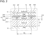
Fig. 2 is a cross-sectional view illustrating the structure of the light-emittinglayer 13.Fig. 2 is a partially enlarged cross-sectional view where the portion ofFig. 1(a) surrounded by the dashed line is enlarged. A description will now be given of the light-emittinglayer 13 in more detail with reference toFig. 2 . The base layer BL of the light-emittinglayer 13 has a first sub-base layer BL1 with a composition of AlxGa1-xN (0 < x ≤ 1) and a second sub-base layer BL2 with a composition of AlyGa1-yN (0 < y ≤ 1) that is formed on the first sub-base layer BL1. The base layer BL has a plurality of sub-base layers composed of a plurality of AlGaN layers whose Al compositions are different from each other. The quantum well layer WA has a composition of InGaN. The barrier layer BA has a composition of GaN. Theelectron blocking layer 14 has a composition of AlzGa1-zN (0 < z ≤ 1). - Of the plurality of base layers BL1 and BL2 of the base layer BL, the Al composition y of the second sub-base layer BL2 is greater than that of the first sub-base layer BL1. Specifically, the Al composition y of the second sub-base layer BL2 is greater than the Al composition x of the first sub-base layer BL1. In this embodiment, y = 1 holds true in the Al composition y. In other words, in this embodiment, the first sub-base layer BL1 has a composition of AlGaN, and the second sub-base layer BL2 has a composition of AlN. The first sub-base layer BL1 has a layer thickness T1 that is greater than the layer thickness of the second sub-base layer BL2. Specifically, the layer thickness T1 of the first sub-base layer BL1 is greater than the layer thickness T2 of the second sub-base layer BL2.
- A description will be hereinbelow given of the light-emitting
layer 13. The base segment BS of the base layer BL can be formed by growing, at a relatively low temperature, an AlGaN layer BL1 and an AlN layer BL2, which serve as the base layer BL, on a GaN layer serving as the n-type semiconductor layer 12. - When a base layer BL different from the n-
type semiconductor layer 12 in terms of crystal composition is grown on the n-type semiconductor layer 12, stress (strain) is generated in the base layer BL. For example, the base layer BL has a smaller lattice constant than that of the n-type semiconductor layer 12. For example, when an AlGaN layer serving as the first sub-base layer BL1 is formed on a GaN layer serving as the n-type semiconductor layer 12, tensile strain is generated in the AlGaN layer due to the GaN layer. Thus, tensile stress is generated in the AlGaN layer during its growth. Also, by forming an AlN layer serving as the second sub-base layer BL2 on the AlGaN layer, the tensile stress further increases. A groove is formed in the AlN layer at the beginning of or during growth of the AlN layer, and the AlN layer grows thereafter in a three-dimensional manner. In other words, the AlN layer is grown in a stereoscopic manner, and a plurality of fine protrusions and recesses are formed. The starting point of formation of this groove is the bottom portion BP of the groove GR. - When the AlN layer is grown at a low temperature, three-dimensional growth of the AlN layer is promoted. Thus, a large number of grooves are formed (the groove GR is formed) on the surface of the AlN layer while being combined with each other, whereby the surface of the AlN layer is partitioned into a plurality of granular segments. The base layer BL with the base segments BS can thus be formed. In this embodiment, the AlGaN layer and the AlN layer are formed as the base layer BL at a growth temperature of 1100°C.
- When an InGaN layer serving as the quantum well layer WA is formed on this base layer BL, the quantum well layer WA is formed as a strained quantum well layer. Also, a certain distribution of the In content is generated within the quantum well layer WA. In other words, the quantum well layer WA is formed such that, for example, the region on the flat portion FL differs from the region on the groove GR in terms of In composition. Furthermore, the layer thickness of the quantum well layer WA on the upper surface of the base segment BS is different from that on the side surface of the base segment BS. Thus, the band gap is not constant within the layer of the quantum well layer WA. Thus, as the light-emitting
layer 13 has fine island-shaped protrusions and recesses, the light-emittinglayer 13 emits various colors of light. - To form the groove GR, the AlN layer (i.e., the second sub-base layer BL2) may be formed directly on the GaN layer. However, due to its large band gap, AlN hinders movement of a carrier (electron) from the n-type semiconductor layer (GaN layer) 12 to the quantum well layer WA. Since the AlGaN layer (first sub-base layer BL1) has an intermediate band gap relative to those of the AlN layer and the GaN layer, hindrance of carrier movement can be reduced. Thus, a decrease in the light-emitting intensity can be suppressed. By configuring the layer thickness of the base layer BL to a level where the tunnel effect of a carrier is produced, movement of an electron to the light-emitting
layer 13 is promoted, and the probability of recombination with a hole increases. - As the size of the base segment BS decreases, the amount of In introduced into the quantum well layer WA increases, and the light-emitting wavelength shifts toward the long wavelength side. Specifically, when an InGaN layer serving as the quantum well layer WA is formed on the AlN layer serving as the second sub-base layer BL2, compressive strain is exerted on the InGaN layer by the AlN layer. When the InGaN layer is subject to compressive strain, In is readily introduced into the InGaN layer. Thus, by forming an InGaN layer on the second sub-base layer BL2 with a high Al composition, an InGaN layer with a high In composition can be formed. This decreases the band gap in the InGaN layer, i.e., the energy between quantum levels. The quantum well layer WA thus emits light with a light-emitting wavelength on the longer wavelength side.
- In this embodiment, the light-emitting
layer 13 emits light whose intensity peaks in a region on the longer wavelength side with reference to the blue region. In a specific example where the layer thickness T1 of the first sub-base layer is set to 6.6 nm, light with a broad wavelength range that has a spectral peak at approximately 530 nm is emitted. - The base layer BL has the first and second sub-base layers BL1 and BL2, whose Al compositions are different from each other. Accordingly, the light-emitting
element 10 is formed so as to have a spectral width over a wide wavelength range. Since the second sub-base layer BL2 is greater than the first sub-base layer BL1 in terms of Al composition, the light-emittinglayer 13 emits light with both a wide light-emitting wavelength range and a high light-emitting intensity. The light-emittinglayer 13 is made to have high color rendering properties and emits light with a high light-emitting intensity. - In this embodiment, the base segment BS of the base layer BL has the flat portion FL. Accordingly, the quantum well layer WA is formed so as to embed the groove GR, and its upper surface is formed as the flat surface FS1. On the upper surface of the quantum well layer WA, a preferable level of crystallinity is thus ensured.
- In this embodiment, the case where the surface of the base layer BL is composed of the flat portion FL and the groove GR was illustrated. However, the surface configuration is not limited to the aforementioned case. For example, the base layer BL may have a curved surface portion on the upper surface of the base segment BS.
- Also, the present inventors examined formation of not a light-emitting layer like the light-emitting
layer 13, but of a multiple quantum well structure having a plurality of quantum well layers which have one flat surface and in which the In composition is changed differently from one another. However, the range of the In composition that can be formed is limited. In the case of a light-emitting element having a light-emitting layer of a multiple quantum well structure with In compositions changed, the spectrum with a wavelength band as wide as that of the light-emittingelement 10 of this embodiment was not possible. Specifically, light with a constant wavelength and a certain level of intensity in a wide range was not acquired. - Light with high color rendering properties could not be extracted by simply increasing the In composition. A quantum well layer with an excessively large In composition was formed to change the In composition in a wide range. In this case, segregation of In was noticeable, and In precipitated and blackened. Also, a portion that does not function as a light-emitting layer was formed. Thus, it can be said that there is a limit in the effort to simultaneously achieve a wider light-emitting spectrum and a higher light-emitting intensity based on the In composition.
- In another example examination, the present inventors manufactured a light-emitting element by laminating light-emitting layers that are formed from different materials and have different band gaps. The simply laminated light-emitting layers respectively composed different materials only emitted light whose peak wavelength corresponds to the band gap, and the spectral intensity between the peaks was small. In this case, extraction of white light was difficult as colors were mixed in an unbalanced and unstable manner. Also, a step of forming light-emitting layers containing different types of materials was added, and the resulting device did not have a preferable level of crystallinity. In this embodiment, on the other hand, by forming a light-emitting
functional layer 13 having a quantum well layer WA of a microstructure, light that has a light-emitting wavelength band (half-value width) in a wide range of the visible region was readily and certainly achieved. - As one example embodiment of the layer thickness of the base layer BL, the present inventors formed the light-emitting
layer 13 with the following layer thicknesses: In the base layer BL, the first sub-base layer BL1 has a layer thickness of 6.6 nm, and the second sub-base layer BL2 has a layer thickness of 1 nm. The size of the base segment BS in the in-plane direction ranges from several tens nm to several µm. - In this embodiment, the case where the quantum well structure layer QW has a structure composed of one quantum well layer WA and one barrier layer BA has been illustrated. However, the quantum well structure layer QW is not limited to the case of being composed of one quantum well layer WA and one barrier layer BA. The quantum well structure layer QW may be composed of a plurality of quantum well layers WA and a plurality of barrier layers BA. In other words, the quantum well structure layer QW may be of a single quantum well (SQW) structure or a multiple quantum well (MQW) structure. In other words, the quantum well structure layer QW needs to have at least one quantum well layer WA and at least one barrier layer BA.
-
Fig. 3 is a cross-sectional view illustrating a structure of a semiconductor light-emittingelement 10A according to a first modified example of the first embodiment. Except for the structure of a base layer BLM of a light-emitting functional layer (light-emitting layer) 13A, the configuration of the light-emittingelement 10A is the same as that of the light-emittingelement 10. In the structure of the base layer BLM of the light-emittinglayer 13A, the first and second sub-base layers BL1 and BL2 in this order are repeatedly laminated three times. - In this modified example, each of the first sub-base layers BL1 has the same layer thickness T3. For example, the layer thickness T3 of each of the first base layers BL1 is 1.5 nm or 2.2 nm. Each of the second sub-base layers BL2 has the same identical layer thickness T2. For example, the layer thickness T2 of each of the second sub-base layer BL2 is 1 nm.
- When the layer thickness T3 of the first sub-base layer BL1 was set to 1.5 nm, the spectral intensity peak was approximately 520 nm. When the layer thickness T3 of the first sub-base layer BL1 was set to 2.2 nm, the spectral strength peak was approximately 535 nm. Light with a broad wavelength band was extracted under the aforementioned conditions.
- In this modified example, a groove is not formed in the first sub-base layer BL1 that is located closest to the n-
type semiconductor layer 12 in the base layer BLM. A groove is formed in the second sub-base layer BL2, which lies above the first sub-base layer BL1. As in the case of the base layer BL according to the first embodiment, the base layer BLM has a groove GR in its surface. In other words, in this modified example, an internal groove is formed at locations of all sub-base layers corresponding to the groove GR, except for the first sub-base layer BL1 that is located closest to the n-type semiconductor layer 12 among the first and second sub-base layers BL1 and BL2. - In this embodiment, each of the first and second sub-base layers BL1 and BL2 of the base layer BLM has a layer thickness of several nm, specifically, a thickness that produces the tunnel effect of a carrier. Thus, reduction of the recombination probability of a carrier is suppressed and a decrease in the light-emitting intensity is mitigated. The groove size and depth can be adjusted by adjusting the composition and layer thickness of each sub-base layer. Accordingly, the structure of the base layer BLM can be controlled at a high level of freedom. To broaden the light-emitting wavelength range, it is preferable that the groove GR be formed in the surface (upper surface) of the base layer BLM and that the base layer BLM be partitioned into the base segments BS.
- In this modified example, the case where the base layer BLM is formed by repeatedly laminating the first and second sub-base layers BL1 and BL2 three times has been illustrated. However, the number of times of repeated lamination of the first and second sub-base layers BL1 and BL2 is not limited to the aforementioned case. The base layer BLM needs to have a structure obtained by repeatedly laminating the first and second sub-base layers BL1 and BL2 in this order a plurality of times.
-
Fig. 4 is a cross-sectional view illustrating a structure of a semiconductor light-emittingelement 10B according to a second modified example of the first embodiment. Except for the configuration of a light-emitting functional layer 13B, the configuration of the light-emittingelement 10B is the same as that of the light-emittingelement 10. The light-emitting functional layer 13B has a structure obtained by laminating a plurality of light-emittinglayers 13 of the first embodiment (two in this modified example). More specifically, the light-emitting functional layer 13B has a base layer BLA, a quantum well layer WA, and a barrier layer BA and is structured such that a base layer BLB, a quantum well layer WB, and a barrier layer BB are layered on the barrier layer BA. - In the structure of the light-emitting functional layer 13B, the first and second light-emitting layers 13B1 and 13B2, whose structures are the same as that of the light-emitting
layer 13, are laminated. The base layer BLA of the first light-emitting layer 13B1 and the base layer BLB of the second light-emitting layer 13B2 have grooves GR1 and GR2 which are formed to be unrelated to each other. Respective bottom portions BP1 and BP2 of the grooves GR1 and GR2 are formed at locations that are unrelated to each other. The base layers BLA and BLB have base segments BS1 and BS2, respectively, which are formed to be unrelated to each other. - The shape and size (particle diameter) of the base segment BS of each of the first and second light-emitting layers 13B1 and 13B2 are adjusted, whereby wavelength peaks of light emitted from the first light-emitting layer 13B1 and light emitted from the second light-emitting layer 13B are different from each other. The number of light-emitting wavelength peaks thus increases compared with the light-emitting
element 10 of the first embodiment that has the light-emittinglayer 13. Accordingly, light can be emitted over a wide wavelength range in a more stable manner. -
Fig. 5 is a cross-sectional view illustrating a structure of a semiconductor light-emittingelement 30 according to a second embodiment. Except for the configuration of a light-emittingfunctional layer 33, the configuration of the light-emittingelement 30 is the same as that of the light-emittingelement 10. The light-emittingfunctional layer 33 has a light-emitting layer (third light-emitting layer) 33A between the n-type semiconductor layer 12 and the light-emittinglayer 13 of the light-emittingelement 10. The third light-emittinglayer 33A has a quantum well structure composed of at least one uniformly flat quantum well layer WC and a plurality of barrier layers BC such that the quantum well layer WC and the barrier layer BC are alternately laminated. - In this embodiment, the third light-emitting
layer 33A has a multiple quantum well (MQW) structure where each of two quantum well layers WC is held between each of three barrier layers BC on the n-type semiconductor layer 13. The light-emitting layer 13 (base layer BL) is formed on the barrier layer BC located closest to the p-type semiconductor layer 15. Each of the quantum well layers WC has the same composition as, for example, the composition of one of the quantum well layers WA and WB, e.g., a composition of InGaN. Each of the barrier layers BC has the same composition as those of the barrier layers BA and BB, e.g., a composition of GaN. The barrier layer BC located closest to the light-emittinglayer 13 of the barrier layers BC has the same composition as that of the n-type semiconductor layer 12. - In the configuration of this embodiment, the third light-emitting
layer 33A of a quantum well structure is added to the side of the n-type semiconductor layer 12 of the light-emittinglayer 13 of the light-emittingelement 10 of the first embodiment. Compared with the first embodiment, additional light with a light-emitting wavelength peak in a pure blue region can be emitted. The configuration according to this embodiment is advantageous for, e.g., increasing the light intensity in the blue region. -
Fig. 6 illustrates the spectral characteristics of light emitted from the light-emittingelement 30. In the drawing, the horizontal axis represents the wavelength, and the vertical axis represents the light-emitting intensity. As illustrated inFig. 6 , the light emitted from the light-emittingelement 30 has two peaks and has a wide spectral width substantially in the entire visible region. Of the two peaks, a peak P1 at approximately 450 nm, which is located closest to the short wavelength side, results from the light emitted from the light-emittinglayer 33A. Likewise, a peak P2 at approximately 520 nm is produced by the light emitted from the light-emittinglayer 13. It was confirmed that when the light-emittinglayer 33A was not provided, i.e., when the light-emittingelement 10 was used, a spectral characteristic identical to that of the light-emittingelement 30 was achieved except for absence of the peak P1. - The case of forming the
electron blocking layer 14 between the light-emitting functional layer (light emitting layer) 13, 13A, 13B, and 33 and the p-type semiconductor layer 15 has been illustrated in these embodiments. However, these embodiments are not limited to the case of providing theelectron blocking layer 14. For example, the p-type semiconductor layer 15 may be formed on the light-emittingfunctional layer 13. Also, theelectron blocking layer 14 has a larger band gap than those of the n-type semiconductor layer 12, the light-emittingfunctional layer 13, and the p-type semiconductor layer 15. Accordingly, an electron can be prevented from overflowing to the side of the p-type semiconductor layer 15 through the light-emittingfunctional layer 13. Therefore, it is preferable to dispose theelectron blocking layer 14 for large-current driving and high-temperature operation. - The first and second embodiments and the first and second modified examples can be combined with each other. For example, a light-emitting functional layer composed of the light-emitting layer 13B and the light-emitting
layer 33A can be formed. Also, the light-emittinglayers - According to the embodiments and modified examples, the light-emitting
layer 13 has the base layer BL which has a composition subject to stress strain from the n-type semiconductor layer 12 and has the plurality of base segments BS formed in a random net shape, and a quantum well structure layer that is formed by embedding the base layer BL and has at least one quantum well layer WA and at least one barrier layer BA. The base layer BL has a plurality of sub-base layers BL1 and BL2 composed of an AlGaN layer, whose Al compositions are different from each other. Accordingly, it is possible to provide a light-emitting element that can emit light with a high light-emitting intensity over a wide range of the visible region. - In this embodiment, the case where the first conductivity type is an n-conductivity type and the second conductivity type is a p-conductivity type, which is opposite to the n-conductivity type. However, the first conductivity type may be a p-type, and the second conductivity type may be an n-type.
-
- 10, 30 semiconductor light-emitting element
- 12 n-type semiconductor layer (first semiconductor layer)
- 13, 13A, 13B, 33 light-emitting functional layer (light-emitting layer)
- 13B1 first light-emitting layer
- 13B2 second light-emitting layer
- 33A third light-emitting layer
- 14 electron blocking layer
- 15 p-type semiconductor layer (second semiconductor layer)
- BL, BLA, BLB base layer
- BL1 first sub-base layer
- BL2 second sub-base layer
- BS, BS1, BS2 base segment
- GR groove
Claims (8)
- A semiconductor light-emitting element comprising: a first semiconductor layer of a first conductivity type; a light-emitting functional layer that is formed on the first semiconductor layer and includes a light-emitting layer; and a second semiconductor layer that is formed on the light-emitting functional layer and is of a conductivity type opposite to a conductivity type of the first semiconductor layer, wherein
the light-emitting layer has: a base layer which has a composition subject to stress strain from the first semiconductor layer and has a plurality of base segments formed in a random net shape; and a quantum well structure layer formed by embedding the base layer and composed of at least one quantum well layer and at least one barrier layer, and
the base layer has a plurality of sub-base layers composed of AlGaN with different Al compositions. - The semiconductor light-emitting element according to claim 1, wherein
the first semiconductor layer has a composition of GaN;
each of the at least one quantum well layer has a composition of InGaN; and
the base layer has the plurality of sub-base layers including a first sub-base layer and a second sub-base layer, wherein the second sub-base layer is formed closer to a side of the second semiconductor layer than the first sub-base layer and has a larger Al composition than an Al composition of the first sub-base layer. - The semiconductor light-emitting element according to claim 1 or 2, wherein the base layer has a structure where the first and second sub-base layers in this order are repeatedly laminated a plurality of times.
- The semiconductor light-emitting element according to any one of claims 1 to 3, wherein the base layer has a layer thickness that causes a tunnel effect of a carrier.
- The semiconductor light-emitting element according to any one of claims 2 to 4, wherein the second sub-base layer has a composition of AlN.
- The semiconductor light-emitting element according to any one of claims 1 to 5, wherein the light-emitting functional layer has a structure where a plurality of the light-emitting layers are laminated.
- The semiconductor light-emitting element according to claim 6, wherein compositions of the base layers of the plurality of the light-emitting layers are different from each other.
- The semiconductor light-emitting element according to claim 6 or 7, wherein the light-emitting functional layer has a light-emitting layer of a quantum well structure composed of at least one quantum well layer and a plurality of barrier layers between the first semiconductor layer and the light-emitting layer located closest to the first semiconductor layer among the plurality of the light-emitting layers.
Applications Claiming Priority (2)
| Application Number | Priority Date | Filing Date | Title |
|---|---|---|---|
| JP2014226919A JP6457784B2 (en) | 2014-11-07 | 2014-11-07 | Semiconductor light emitting device |
| PCT/JP2015/079807 WO2016072277A1 (en) | 2014-11-07 | 2015-10-22 | Semiconductor light-emitting device |
Publications (3)
| Publication Number | Publication Date |
|---|---|
| EP3217441A1 true EP3217441A1 (en) | 2017-09-13 |
| EP3217441A4 EP3217441A4 (en) | 2018-06-13 |
| EP3217441B1 EP3217441B1 (en) | 2019-07-17 |
Family
ID=55909004
Family Applications (1)
| Application Number | Title | Priority Date | Filing Date |
|---|---|---|---|
| EP15858018.3A Active EP3217441B1 (en) | 2014-11-07 | 2015-10-22 | Semiconductor light-emitting device |
Country Status (6)
| Country | Link |
|---|---|
| US (1) | US10056524B2 (en) |
| EP (1) | EP3217441B1 (en) |
| JP (1) | JP6457784B2 (en) |
| KR (1) | KR102397663B1 (en) |
| CN (1) | CN107004743B (en) |
| WO (1) | WO2016072277A1 (en) |
Cited By (1)
| Publication number | Priority date | Publication date | Assignee | Title |
|---|---|---|---|---|
| EP3217440A4 (en) * | 2014-11-07 | 2018-06-13 | Stanley Electric Co., Ltd. | Semiconductor light-emitting element |
Families Citing this family (7)
| Publication number | Priority date | Publication date | Assignee | Title |
|---|---|---|---|---|
| JP6433246B2 (en) | 2014-11-07 | 2018-12-05 | スタンレー電気株式会社 | Semiconductor light emitting device |
| JP6457784B2 (en) | 2014-11-07 | 2019-01-23 | スタンレー電気株式会社 | Semiconductor light emitting device |
| JP6433247B2 (en) | 2014-11-07 | 2018-12-05 | スタンレー電気株式会社 | Semiconductor light emitting device |
| JP6651167B2 (en) | 2015-03-23 | 2020-02-19 | スタンレー電気株式会社 | Semiconductor light emitting device and method of manufacturing the same |
| KR102569461B1 (en) * | 2015-11-30 | 2023-09-04 | 쑤저우 레킨 세미컨덕터 컴퍼니 리미티드 | Light emitting device and lighting apparatus including the same |
| JP2017220586A (en) * | 2016-06-08 | 2017-12-14 | 国立大学法人 東京大学 | Semiconductor light-emitting device |
| WO2022109797A1 (en) * | 2020-11-24 | 2022-06-02 | 苏州晶湛半导体有限公司 | Multi-wavelength led structure and manufacturing method therefor |
Family Cites Families (28)
| Publication number | Priority date | Publication date | Assignee | Title |
|---|---|---|---|---|
| US6608330B1 (en) | 1998-09-21 | 2003-08-19 | Nichia Corporation | Light emitting device |
| JP4047150B2 (en) | 2002-11-28 | 2008-02-13 | ローム株式会社 | Semiconductor light emitting device |
| JP2005093682A (en) | 2003-09-17 | 2005-04-07 | Toyoda Gosei Co Ltd | GaN-BASED SEMICONDUCTOR LIGHT EMITTING ELEMENT AND ITS MANUFACTURING METHOD |
| TWI247439B (en) | 2004-12-17 | 2006-01-11 | Genesis Photonics Inc | Light-emitting diode device |
| KR100691177B1 (en) | 2005-05-31 | 2007-03-09 | 삼성전기주식회사 | White light emitting device |
| JP4984119B2 (en) * | 2006-08-28 | 2012-07-25 | スタンレー電気株式会社 | Nitride semiconductor crystal or light emitting device using the same and method for manufacturing the same |
| JP2008071805A (en) | 2006-09-12 | 2008-03-27 | Institute Of National Colleges Of Technology Japan | Multi-wavelength light-emitting device for coating not less than two kinds of semiconductor light-emitting elements with a plurality of types of phosphors |
| JP2010510661A (en) * | 2006-11-15 | 2010-04-02 | ザ リージェンツ オブ ザ ユニバーシティ オブ カリフォルニア | Light extraction diode (LED) with high light extraction efficiency by multiple extractors |
| KR100809229B1 (en) | 2006-11-20 | 2008-03-05 | 삼성전기주식회사 | Nitride semiconductor light emitting device and manufacturing method of the same |
| TWI321366B (en) * | 2007-02-09 | 2010-03-01 | Huga Optotech Inc | Epi-structure with uneven multi-quantum well and the method thereof |
| JP5050574B2 (en) | 2007-03-05 | 2012-10-17 | 住友電気工業株式会社 | Group III nitride semiconductor light emitting device |
| KR101164026B1 (en) * | 2007-07-12 | 2012-07-18 | 삼성전자주식회사 | Nitride semiconductor light emitting device and fabrication method thereof |
| TWI381547B (en) | 2007-11-14 | 2013-01-01 | Advanced Optoelectronic Tech | Light emitting device of iii-nitride based semiconductor and manufacturing method thereof |
| CN101452980B (en) * | 2007-11-30 | 2012-03-21 | 展晶科技(深圳)有限公司 | Production method of group III nitride compound semiconductor LED |
| JP2010232597A (en) | 2009-03-30 | 2010-10-14 | Toyoda Gosei Co Ltd | Group-iii nitride compound semiconductor light-emitting element and method of manufacturing the same |
| JP2011249460A (en) | 2010-05-25 | 2011-12-08 | Meijo University | White light emitting diode |
| WO2012059837A1 (en) | 2010-11-04 | 2012-05-10 | Koninklijke Philips Electronics N.V. | Solid state light emitting devices based on crystallographically relaxed structures |
| JP2012169383A (en) * | 2011-02-11 | 2012-09-06 | Toyoda Gosei Co Ltd | Group iii nitride semiconductor light-emitting element and method of manufacturing the same |
| KR101804408B1 (en) * | 2011-09-05 | 2017-12-04 | 엘지이노텍 주식회사 | Light emitting device |
| KR101827973B1 (en) * | 2011-09-06 | 2018-02-13 | 엘지이노텍 주식회사 | Light emitting device |
| WO2013114152A1 (en) | 2012-01-31 | 2013-08-08 | Soitec | Photoactive devices with improved distribution of charge carriers, and methods of forming same |
| KR20130106690A (en) | 2012-03-20 | 2013-09-30 | 삼성전자주식회사 | White light emitting diode |
| EP2856521B1 (en) | 2012-05-24 | 2020-12-09 | Versitech Limited | White nanoled without requiring color conversion |
| US9024292B2 (en) | 2012-06-02 | 2015-05-05 | Xiaohang Li | Monolithic semiconductor light emitting devices and methods of making the same |
| WO2014171048A1 (en) | 2013-04-16 | 2014-10-23 | パナソニック株式会社 | Silicon carbide semiconductor device and method for manufacturing same |
| KR102212561B1 (en) | 2014-08-11 | 2021-02-08 | 삼성전자주식회사 | Semiconductor light emitting device and semiconductor light emitting device package |
| JP6457784B2 (en) | 2014-11-07 | 2019-01-23 | スタンレー電気株式会社 | Semiconductor light emitting device |
| JP6433246B2 (en) * | 2014-11-07 | 2018-12-05 | スタンレー電気株式会社 | Semiconductor light emitting device |
-
2014
- 2014-11-07 JP JP2014226919A patent/JP6457784B2/en active Active
-
2015
- 2015-10-22 US US15/525,057 patent/US10056524B2/en active Active
- 2015-10-22 WO PCT/JP2015/079807 patent/WO2016072277A1/en active Application Filing
- 2015-10-22 KR KR1020177012270A patent/KR102397663B1/en active IP Right Grant
- 2015-10-22 EP EP15858018.3A patent/EP3217441B1/en active Active
- 2015-10-22 CN CN201580060595.2A patent/CN107004743B/en active Active
Cited By (1)
| Publication number | Priority date | Publication date | Assignee | Title |
|---|---|---|---|---|
| EP3217440A4 (en) * | 2014-11-07 | 2018-06-13 | Stanley Electric Co., Ltd. | Semiconductor light-emitting element |
Also Published As
| Publication number | Publication date |
|---|---|
| EP3217441B1 (en) | 2019-07-17 |
| US10056524B2 (en) | 2018-08-21 |
| CN107004743B (en) | 2019-07-02 |
| JP6457784B2 (en) | 2019-01-23 |
| WO2016072277A1 (en) | 2016-05-12 |
| EP3217441A4 (en) | 2018-06-13 |
| KR20170080600A (en) | 2017-07-10 |
| US20170317232A1 (en) | 2017-11-02 |
| CN107004743A (en) | 2017-08-01 |
| JP2016092286A (en) | 2016-05-23 |
| KR102397663B1 (en) | 2022-05-13 |
Similar Documents
| Publication | Publication Date | Title |
|---|---|---|
| EP3217441B1 (en) | Semiconductor light-emitting device | |
| US10270045B2 (en) | Semiconductor light-emitting element | |
| US10186671B2 (en) | Semiconductor light-emitting element | |
| US10062805B2 (en) | Semiconductor light-emitting element | |
| EP3276674B1 (en) | Semiconductor light-emitting element | |
| EP3276676B1 (en) | Semiconductor light-emitting element and method of manufacturing the same | |
| US10186634B2 (en) | Semiconductor light-emitting element | |
| KR20190039586A (en) | Optoelectronic component | |
| EP3276677B1 (en) | Semiconductor light-emitting element | |
| TWI533467B (en) | An epitaxy structure of light emitting elements |
Legal Events
| Date | Code | Title | Description |
|---|---|---|---|
| STAA | Information on the status of an ep patent application or granted ep patent |
Free format text: STATUS: THE INTERNATIONAL PUBLICATION HAS BEEN MADE |
|
| PUAI | Public reference made under article 153(3) epc to a published international application that has entered the european phase |
Free format text: ORIGINAL CODE: 0009012 |
|
| STAA | Information on the status of an ep patent application or granted ep patent |
Free format text: STATUS: REQUEST FOR EXAMINATION WAS MADE |
|
| 17P | Request for examination filed |
Effective date: 20170503 |
|
| AK | Designated contracting states |
Kind code of ref document: A1 Designated state(s): AL AT BE BG CH CY CZ DE DK EE ES FI FR GB GR HR HU IE IS IT LI LT LU LV MC MK MT NL NO PL PT RO RS SE SI SK SM TR |
|
| AX | Request for extension of the european patent |
Extension state: BA ME |
|
| DAV | Request for validation of the european patent (deleted) | ||
| DAX | Request for extension of the european patent (deleted) | ||
| A4 | Supplementary search report drawn up and despatched |
Effective date: 20180511 |
|
| RIC1 | Information provided on ipc code assigned before grant |
Ipc: H01L 33/12 20100101ALI20180504BHEP Ipc: H01L 33/24 20100101AFI20180504BHEP Ipc: H01L 33/08 20100101ALI20180504BHEP Ipc: H01L 33/32 20100101ALI20180504BHEP |
|
| GRAP | Despatch of communication of intention to grant a patent |
Free format text: ORIGINAL CODE: EPIDOSNIGR1 |
|
| STAA | Information on the status of an ep patent application or granted ep patent |
Free format text: STATUS: GRANT OF PATENT IS INTENDED |
|
| INTG | Intention to grant announced |
Effective date: 20190130 |
|
| GRAS | Grant fee paid |
Free format text: ORIGINAL CODE: EPIDOSNIGR3 |
|
| GRAA | (expected) grant |
Free format text: ORIGINAL CODE: 0009210 |
|
| STAA | Information on the status of an ep patent application or granted ep patent |
Free format text: STATUS: THE PATENT HAS BEEN GRANTED |
|
| AK | Designated contracting states |
Kind code of ref document: B1 Designated state(s): AL AT BE BG CH CY CZ DE DK EE ES FI FR GB GR HR HU IE IS IT LI LT LU LV MC MK MT NL NO PL PT RO RS SE SI SK SM TR |
|
| REG | Reference to a national code |
Ref country code: GB Ref legal event code: FG4D |
|
| REG | Reference to a national code |
Ref country code: CH Ref legal event code: EP |
|
| REG | Reference to a national code |
Ref country code: IE Ref legal event code: FG4D |
|
| REG | Reference to a national code |
Ref country code: DE Ref legal event code: R096 Ref document number: 602015034072 Country of ref document: DE |
|
| REG | Reference to a national code |
Ref country code: AT Ref legal event code: REF Ref document number: 1156649 Country of ref document: AT Kind code of ref document: T Effective date: 20190815 |
|
| REG | Reference to a national code |
Ref country code: NL Ref legal event code: MP Effective date: 20190717 |
|
| REG | Reference to a national code |
Ref country code: LT Ref legal event code: MG4D |
|
| REG | Reference to a national code |
Ref country code: AT Ref legal event code: MK05 Ref document number: 1156649 Country of ref document: AT Kind code of ref document: T Effective date: 20190717 |
|
| PG25 | Lapsed in a contracting state [announced via postgrant information from national office to epo] |
Ref country code: FI Free format text: LAPSE BECAUSE OF FAILURE TO SUBMIT A TRANSLATION OF THE DESCRIPTION OR TO PAY THE FEE WITHIN THE PRESCRIBED TIME-LIMIT Effective date: 20190717 Ref country code: LT Free format text: LAPSE BECAUSE OF FAILURE TO SUBMIT A TRANSLATION OF THE DESCRIPTION OR TO PAY THE FEE WITHIN THE PRESCRIBED TIME-LIMIT Effective date: 20190717 Ref country code: SE Free format text: LAPSE BECAUSE OF FAILURE TO SUBMIT A TRANSLATION OF THE DESCRIPTION OR TO PAY THE FEE WITHIN THE PRESCRIBED TIME-LIMIT Effective date: 20190717 Ref country code: HR Free format text: LAPSE BECAUSE OF FAILURE TO SUBMIT A TRANSLATION OF THE DESCRIPTION OR TO PAY THE FEE WITHIN THE PRESCRIBED TIME-LIMIT Effective date: 20190717 Ref country code: NO Free format text: LAPSE BECAUSE OF FAILURE TO SUBMIT A TRANSLATION OF THE DESCRIPTION OR TO PAY THE FEE WITHIN THE PRESCRIBED TIME-LIMIT Effective date: 20191017 Ref country code: AT Free format text: LAPSE BECAUSE OF FAILURE TO SUBMIT A TRANSLATION OF THE DESCRIPTION OR TO PAY THE FEE WITHIN THE PRESCRIBED TIME-LIMIT Effective date: 20190717 Ref country code: PT Free format text: LAPSE BECAUSE OF FAILURE TO SUBMIT A TRANSLATION OF THE DESCRIPTION OR TO PAY THE FEE WITHIN THE PRESCRIBED TIME-LIMIT Effective date: 20191118 Ref country code: BG Free format text: LAPSE BECAUSE OF FAILURE TO SUBMIT A TRANSLATION OF THE DESCRIPTION OR TO PAY THE FEE WITHIN THE PRESCRIBED TIME-LIMIT Effective date: 20191017 Ref country code: NL Free format text: LAPSE BECAUSE OF FAILURE TO SUBMIT A TRANSLATION OF THE DESCRIPTION OR TO PAY THE FEE WITHIN THE PRESCRIBED TIME-LIMIT Effective date: 20190717 |
|
| PG25 | Lapsed in a contracting state [announced via postgrant information from national office to epo] |
Ref country code: LV Free format text: LAPSE BECAUSE OF FAILURE TO SUBMIT A TRANSLATION OF THE DESCRIPTION OR TO PAY THE FEE WITHIN THE PRESCRIBED TIME-LIMIT Effective date: 20190717 Ref country code: ES Free format text: LAPSE BECAUSE OF FAILURE TO SUBMIT A TRANSLATION OF THE DESCRIPTION OR TO PAY THE FEE WITHIN THE PRESCRIBED TIME-LIMIT Effective date: 20190717 Ref country code: AL Free format text: LAPSE BECAUSE OF FAILURE TO SUBMIT A TRANSLATION OF THE DESCRIPTION OR TO PAY THE FEE WITHIN THE PRESCRIBED TIME-LIMIT Effective date: 20190717 Ref country code: RS Free format text: LAPSE BECAUSE OF FAILURE TO SUBMIT A TRANSLATION OF THE DESCRIPTION OR TO PAY THE FEE WITHIN THE PRESCRIBED TIME-LIMIT Effective date: 20190717 Ref country code: IS Free format text: LAPSE BECAUSE OF FAILURE TO SUBMIT A TRANSLATION OF THE DESCRIPTION OR TO PAY THE FEE WITHIN THE PRESCRIBED TIME-LIMIT Effective date: 20191117 Ref country code: GR Free format text: LAPSE BECAUSE OF FAILURE TO SUBMIT A TRANSLATION OF THE DESCRIPTION OR TO PAY THE FEE WITHIN THE PRESCRIBED TIME-LIMIT Effective date: 20191018 |
|
| PG25 | Lapsed in a contracting state [announced via postgrant information from national office to epo] |
Ref country code: TR Free format text: LAPSE BECAUSE OF FAILURE TO SUBMIT A TRANSLATION OF THE DESCRIPTION OR TO PAY THE FEE WITHIN THE PRESCRIBED TIME-LIMIT Effective date: 20190717 |
|
| PG25 | Lapsed in a contracting state [announced via postgrant information from national office to epo] |
Ref country code: PL Free format text: LAPSE BECAUSE OF FAILURE TO SUBMIT A TRANSLATION OF THE DESCRIPTION OR TO PAY THE FEE WITHIN THE PRESCRIBED TIME-LIMIT Effective date: 20190717 Ref country code: DK Free format text: LAPSE BECAUSE OF FAILURE TO SUBMIT A TRANSLATION OF THE DESCRIPTION OR TO PAY THE FEE WITHIN THE PRESCRIBED TIME-LIMIT Effective date: 20190717 Ref country code: EE Free format text: LAPSE BECAUSE OF FAILURE TO SUBMIT A TRANSLATION OF THE DESCRIPTION OR TO PAY THE FEE WITHIN THE PRESCRIBED TIME-LIMIT Effective date: 20190717 Ref country code: RO Free format text: LAPSE BECAUSE OF FAILURE TO SUBMIT A TRANSLATION OF THE DESCRIPTION OR TO PAY THE FEE WITHIN THE PRESCRIBED TIME-LIMIT Effective date: 20190717 Ref country code: IT Free format text: LAPSE BECAUSE OF FAILURE TO SUBMIT A TRANSLATION OF THE DESCRIPTION OR TO PAY THE FEE WITHIN THE PRESCRIBED TIME-LIMIT Effective date: 20190717 |
|
| PG25 | Lapsed in a contracting state [announced via postgrant information from national office to epo] |
Ref country code: SM Free format text: LAPSE BECAUSE OF FAILURE TO SUBMIT A TRANSLATION OF THE DESCRIPTION OR TO PAY THE FEE WITHIN THE PRESCRIBED TIME-LIMIT Effective date: 20190717 Ref country code: IS Free format text: LAPSE BECAUSE OF FAILURE TO SUBMIT A TRANSLATION OF THE DESCRIPTION OR TO PAY THE FEE WITHIN THE PRESCRIBED TIME-LIMIT Effective date: 20200224 Ref country code: SK Free format text: LAPSE BECAUSE OF FAILURE TO SUBMIT A TRANSLATION OF THE DESCRIPTION OR TO PAY THE FEE WITHIN THE PRESCRIBED TIME-LIMIT Effective date: 20190717 Ref country code: MC Free format text: LAPSE BECAUSE OF FAILURE TO SUBMIT A TRANSLATION OF THE DESCRIPTION OR TO PAY THE FEE WITHIN THE PRESCRIBED TIME-LIMIT Effective date: 20190717 Ref country code: CZ Free format text: LAPSE BECAUSE OF FAILURE TO SUBMIT A TRANSLATION OF THE DESCRIPTION OR TO PAY THE FEE WITHIN THE PRESCRIBED TIME-LIMIT Effective date: 20190717 |
|
| REG | Reference to a national code |
Ref country code: CH Ref legal event code: PL |
|
| REG | Reference to a national code |
Ref country code: DE Ref legal event code: R097 Ref document number: 602015034072 Country of ref document: DE |
|
| PLBE | No opposition filed within time limit |
Free format text: ORIGINAL CODE: 0009261 |
|
| STAA | Information on the status of an ep patent application or granted ep patent |
Free format text: STATUS: NO OPPOSITION FILED WITHIN TIME LIMIT |
|
| PG2D | Information on lapse in contracting state deleted |
Ref country code: IS |
|
| PG25 | Lapsed in a contracting state [announced via postgrant information from national office to epo] |
Ref country code: CH Free format text: LAPSE BECAUSE OF NON-PAYMENT OF DUE FEES Effective date: 20191031 Ref country code: LU Free format text: LAPSE BECAUSE OF NON-PAYMENT OF DUE FEES Effective date: 20191022 Ref country code: LI Free format text: LAPSE BECAUSE OF NON-PAYMENT OF DUE FEES Effective date: 20191031 |
|
| 26N | No opposition filed |
Effective date: 20200603 |
|
| REG | Reference to a national code |
Ref country code: BE Ref legal event code: MM Effective date: 20191031 |
|
| PG25 | Lapsed in a contracting state [announced via postgrant information from national office to epo] |
Ref country code: SI Free format text: LAPSE BECAUSE OF FAILURE TO SUBMIT A TRANSLATION OF THE DESCRIPTION OR TO PAY THE FEE WITHIN THE PRESCRIBED TIME-LIMIT Effective date: 20190717 Ref country code: BE Free format text: LAPSE BECAUSE OF NON-PAYMENT OF DUE FEES Effective date: 20191031 |
|
| PG25 | Lapsed in a contracting state [announced via postgrant information from national office to epo] |
Ref country code: IE Free format text: LAPSE BECAUSE OF NON-PAYMENT OF DUE FEES Effective date: 20191022 |
|
| PG25 | Lapsed in a contracting state [announced via postgrant information from national office to epo] |
Ref country code: CY Free format text: LAPSE BECAUSE OF FAILURE TO SUBMIT A TRANSLATION OF THE DESCRIPTION OR TO PAY THE FEE WITHIN THE PRESCRIBED TIME-LIMIT Effective date: 20190717 |
|
| PG25 | Lapsed in a contracting state [announced via postgrant information from national office to epo] |
Ref country code: HU Free format text: LAPSE BECAUSE OF FAILURE TO SUBMIT A TRANSLATION OF THE DESCRIPTION OR TO PAY THE FEE WITHIN THE PRESCRIBED TIME-LIMIT; INVALID AB INITIO Effective date: 20151022 Ref country code: MT Free format text: LAPSE BECAUSE OF FAILURE TO SUBMIT A TRANSLATION OF THE DESCRIPTION OR TO PAY THE FEE WITHIN THE PRESCRIBED TIME-LIMIT Effective date: 20190717 |
|
| PG25 | Lapsed in a contracting state [announced via postgrant information from national office to epo] |
Ref country code: MK Free format text: LAPSE BECAUSE OF FAILURE TO SUBMIT A TRANSLATION OF THE DESCRIPTION OR TO PAY THE FEE WITHIN THE PRESCRIBED TIME-LIMIT Effective date: 20190717 |
|
| PGFP | Annual fee paid to national office [announced via postgrant information from national office to epo] |
Ref country code: GB Payment date: 20230831 Year of fee payment: 9 |
|
| PGFP | Annual fee paid to national office [announced via postgrant information from national office to epo] |
Ref country code: FR Payment date: 20230911 Year of fee payment: 9 |
|
| PGFP | Annual fee paid to national office [announced via postgrant information from national office to epo] |
Ref country code: DE Payment date: 20230830 Year of fee payment: 9 |