EP3217408A2 - Focussing module for a form filter and form filter for adjusting a spatial intensity distribution of a x-ray beam - Google Patents
Focussing module for a form filter and form filter for adjusting a spatial intensity distribution of a x-ray beam Download PDFInfo
- Publication number
- EP3217408A2 EP3217408A2 EP17173761.2A EP17173761A EP3217408A2 EP 3217408 A2 EP3217408 A2 EP 3217408A2 EP 17173761 A EP17173761 A EP 17173761A EP 3217408 A2 EP3217408 A2 EP 3217408A2
- Authority
- EP
- European Patent Office
- Prior art keywords
- groove
- frame
- pairs
- opening
- guide rail
- Prior art date
- Legal status (The legal status is an assumption and is not a legal conclusion. Google has not performed a legal analysis and makes no representation as to the accuracy of the status listed.)
- Granted
Links
- 238000009826 distribution Methods 0.000 title claims abstract description 12
- 238000003475 lamination Methods 0.000 claims abstract description 47
- 238000002059 diagnostic imaging Methods 0.000 claims description 18
- 241000446313 Lamella Species 0.000 claims description 12
- 238000004519 manufacturing process Methods 0.000 claims description 8
- 239000000463 material Substances 0.000 claims description 8
- 238000007493 shaping process Methods 0.000 claims description 7
- 238000002591 computed tomography Methods 0.000 claims description 6
- 239000000654 additive Substances 0.000 claims description 5
- 230000000996 additive effect Effects 0.000 claims description 5
- 238000003780 insertion Methods 0.000 claims description 5
- 230000037431 insertion Effects 0.000 claims description 5
- 239000004065 semiconductor Substances 0.000 claims description 3
- 230000005855 radiation Effects 0.000 description 18
- 238000010521 absorption reaction Methods 0.000 description 5
- 238000003384 imaging method Methods 0.000 description 4
- 238000000034 method Methods 0.000 description 3
- NJPPVKZQTLUDBO-UHFFFAOYSA-N novaluron Chemical compound C1=C(Cl)C(OC(F)(F)C(OC(F)(F)F)F)=CC=C1NC(=O)NC(=O)C1=C(F)C=CC=C1F NJPPVKZQTLUDBO-UHFFFAOYSA-N 0.000 description 3
- 238000012216 screening Methods 0.000 description 3
- OKTJSMMVPCPJKN-UHFFFAOYSA-N Carbon Chemical compound [C] OKTJSMMVPCPJKN-UHFFFAOYSA-N 0.000 description 2
- 229920000049 Carbon (fiber) Polymers 0.000 description 2
- 230000001133 acceleration Effects 0.000 description 2
- XAGFODPZIPBFFR-UHFFFAOYSA-N aluminium Chemical compound [Al] XAGFODPZIPBFFR-UHFFFAOYSA-N 0.000 description 2
- 229910052782 aluminium Inorganic materials 0.000 description 2
- 238000003491 array Methods 0.000 description 2
- 229910052799 carbon Inorganic materials 0.000 description 2
- 239000004917 carbon fiber Substances 0.000 description 2
- 239000002131 composite material Substances 0.000 description 2
- VNWKTOKETHGBQD-UHFFFAOYSA-N methane Chemical compound C VNWKTOKETHGBQD-UHFFFAOYSA-N 0.000 description 2
- 238000003860 storage Methods 0.000 description 2
- WFKWXMTUELFFGS-UHFFFAOYSA-N tungsten Chemical compound [W] WFKWXMTUELFFGS-UHFFFAOYSA-N 0.000 description 2
- 229910052721 tungsten Inorganic materials 0.000 description 2
- 239000010937 tungsten Substances 0.000 description 2
- 238000010146 3D printing Methods 0.000 description 1
- 229910001080 W alloy Inorganic materials 0.000 description 1
- 239000000853 adhesive Substances 0.000 description 1
- 230000001070 adhesive effect Effects 0.000 description 1
- 230000002238 attenuated effect Effects 0.000 description 1
- 239000004918 carbon fiber reinforced polymer Substances 0.000 description 1
- 239000000919 ceramic Substances 0.000 description 1
- 230000001419 dependent effect Effects 0.000 description 1
- 230000005670 electromagnetic radiation Effects 0.000 description 1
- 230000003628 erosive effect Effects 0.000 description 1
- 238000005530 etching Methods 0.000 description 1
- -1 for example Substances 0.000 description 1
- 230000005484 gravity Effects 0.000 description 1
- 230000003993 interaction Effects 0.000 description 1
- 239000004033 plastic Substances 0.000 description 1
- 229920003023 plastic Polymers 0.000 description 1
- 238000002600 positron emission tomography Methods 0.000 description 1
- 230000000644 propagated effect Effects 0.000 description 1
- 229910052710 silicon Inorganic materials 0.000 description 1
- 239000010703 silicon Substances 0.000 description 1
- 238000002603 single-photon emission computed tomography Methods 0.000 description 1
- 239000007787 solid Substances 0.000 description 1
- 230000003595 spectral effect Effects 0.000 description 1
- 239000000725 suspension Substances 0.000 description 1
- 230000001225 therapeutic effect Effects 0.000 description 1
Images


Classifications
-
- G—PHYSICS
- G21—NUCLEAR PHYSICS; NUCLEAR ENGINEERING
- G21K—TECHNIQUES FOR HANDLING PARTICLES OR IONISING RADIATION NOT OTHERWISE PROVIDED FOR; IRRADIATION DEVICES; GAMMA RAY OR X-RAY MICROSCOPES
- G21K1/00—Arrangements for handling particles or ionising radiation, e.g. focusing or moderating
- G21K1/02—Arrangements for handling particles or ionising radiation, e.g. focusing or moderating using diaphragms, collimators
- G21K1/025—Arrangements for handling particles or ionising radiation, e.g. focusing or moderating using diaphragms, collimators using multiple collimators, e.g. Bucky screens; other devices for eliminating undesired or dispersed radiation
-
- G—PHYSICS
- G21—NUCLEAR PHYSICS; NUCLEAR ENGINEERING
- G21K—TECHNIQUES FOR HANDLING PARTICLES OR IONISING RADIATION NOT OTHERWISE PROVIDED FOR; IRRADIATION DEVICES; GAMMA RAY OR X-RAY MICROSCOPES
- G21K1/00—Arrangements for handling particles or ionising radiation, e.g. focusing or moderating
- G21K1/10—Scattering devices; Absorbing devices; Ionising radiation filters
Definitions
- the invention relates to a focusing module for a shape filter for adjusting a spatial intensity distribution of an X-ray beam.
- the invention further relates to a shape filter for adjusting a spatial intensity distribution of an X-ray, an irradiation arrangement and a medical imaging device.
- the spatial intensity distribution of the X-ray beam for example, as a function of physiological and / or anatomical parameters of the patient.
- a radiation incident on the patient head-on covers a significantly shorter distance through the patient and, consequently, a significantly lower absorption than radiation incident on the side of the patient for example propagated from one shoulder to the opposite shoulder.
- US 7403597 B2 discloses an aperture device for an X-ray device provided for scanning an object.
- US 8873704 B2 discloses a filter for an X-ray device for forming an intensity profile of X-ray radiation emanating from an X-ray source.
- the focus line may in particular be a straight line and / or have the focal point.
- the frame may comprise a first crossbar forming a first long side of the through opening.
- the frame may have a second crossbar forming a second long side of the through opening.
- the frame may have a first side part, which forms a first short side of the through-opening.
- the frame may have a second side part, which forms a second short side of the through opening.
- the first crossbar and / or the second crossbar may be made of aluminum, for example.
- a crossbar may be a single component or a composite assembly having multiple components.
- a side part may be, for example, a single component or a composite assembly having a plurality of components.
- a first stop means may be formed, wherein the lamella plate along the first groove is insertable until a positive connection of the lamella plate with the first stop means, wherein the positive connection of the lamination plate with the first stop means further insertion of the lamination plate along the counteracts first groove.
- the first stop means may be formed based on an additive manufacturing process and / or an abrasive manufacturing process or connected to the frame, for example, glued be.
- the first stop means may be formed for example in the form of a stop rail.
- a second stop means may be formed, wherein the lamella plate along the second groove is insertable up to a positive connection of the lamellar plate with the second stop means, wherein the positive connection of the lamination plate with the second stop means further insertion of the lamination plate along the counteracts second groove.
- the second stop means may be formed based on an additive manufacturing process and / or an abrasive manufacturing process or connected to the frame, for example glued.
- the second stop means can, for example be formed in the form of a rail which extends along the frame.
- the focusing module may further comprise a first guide rail and a second guide rail.
- the respective first grooves of the groove pairs may be formed in the first guide rail.
- the respective second grooves of the groove pairs may be formed in the second guide rail.
- the first guide rail and / or the second guide rail can be produced, for example, in the form of a strip made of a dimensionally stable and radiation-resistant material, in particular plastic.
- this strip grooves can be formed by structuring.
- Crystalline semiconductors such as, for example, silicon, ceramic carbon fiber reinforced carbon, carbon fiber reinforced plastic or combinations thereof are particularly suitable as a dimensionally stable and radiation resistant material.
- first guide rail and / or the second guide rail may be made of a crystalline semiconductor material.
- the groove pairs may be formed based on an additive manufacturing process and / or an abrasive manufacturing process.
- the first groove and / or the second groove may be fabricated using an additive process such as 3D printing and / or using a removing process such as wire eroding or etching.
- the arrangement of groove pairs has a plurality of groove pairs.
- the focusing module can have a plurality of arrangements of groove pairs, with each arrangement of groove pairs each having a focal point and / or a focus line being assignable.
- a first arrangement which is formed by groove pairs, which are arranged in the center of the focusing module, a first focus line is assigned and that a second arrangement, which is formed by groove pairs, which are arranged outside the center of the focusing module, a second focus line is assigned.
- the second focus line may be closer to the focusing module than the first focus line or vice versa.
- the invention further relates to a shape filter for adjusting a spatial intensity distribution of an X-ray beam, comprising a focussing module according to the invention and a plurality of lamination plates which are each received in a groove pair of the arrangement of groove pairs and inserted into the through hole.
- the arrangement of the laminations so the width, length and height of the laminations and the distance and the angle between adjacent laminations, can be freely selected in many areas. This allows, for example, different shaft ratios for the tunnel-shaped opening or different line frequencies, also along the same guide rail realize.
- the lamination plates may be made of tungsten and / or of a tungsten alloy. With tungsten, a high absorption of X-rays can be realized. As a result, in particular scattered radiation and spectral beam hardening of the X-ray beam can be minimized.
- the lamellar sheets can be precisely and permanently aligned in the guide rails to the focal point and / or the focus line.
- the laminations can be fixed against wobbling and slipping out in the groove pairs.
- the fixing of the laminations in the first groove and / or in the second groove can be made for example by an adhesive or with the aid of stop rails.
- a computed tomography device is exemplified for a medical imaging device.
- the groove pairs NP are arranged side by side along the through hole H so as to be in different planes E each having the focal point T and intersecting in the focus line TL.
- the groove pairs NP each have a first groove N1 and a second groove N2 opposite to the first groove N1 with respect to the through hole H.
- the first groove N1 and the second groove N2 are formed such that a lamination sheet L is receivable at two opposite edges of the lamination sheet L in the first groove N1 and the second groove N2 and along the first groove N1 and the second groove N2 in the continuous one Opening H is insertable.
- the first groove N1 is open only from the front end side of the guide rail RN1, so that lamination sheets L can be used from this direction but can not slip out on the back.
- the tolerances in particular for the width YN and depth ZN, for example, be about 10 microns.
- the distance from the focal point T to the first groove N1 and / or to the second groove N2 may be approximately 220 millimeters, for example.
- the acquisition region 4 is located in the tunnel-shaped opening 9.
- a region of the patient 13 to be imaged can be positioned so that the radiation 27 can reach the region to be imaged from the radiation source 26 and, after interacting with the region to be imaged, to the radiation detector 28 can get.
- the medical imaging device 1 is configured to acquire acquisition data based on electromagnetic radiation 27.
- the medical imaging device 1 has an acquisition unit.
- the acquisition unit is a projection data acquisition unit with the radiation source 26, e.g. B. an X-ray source, and the detector 28, z. B. an X-ray detector, in particular an energy-resolving X-ray detector.
- the medical imaging device 1 has an input device 38 and an output device 39, which are each connected to the control device 30.
- the input device 38 is for inputting control information, e.g. B. image reconstruction parameters, examination parameters or the like.
- the output device 39 is designed in particular for outputting control information, images and / or acoustic signals.
- holes RCS, RCM for example, with threads
- the various parts of the frame R in particular the transverse beams RL1, RL2 and the side parts RS1, RS2, can be connected to one another by means of the bores RCS.
- the frame R can be connected to an actuator PFA of the positioning unit PF.
Abstract
Die Erfindung betrifft ein Fokussierungsmodul für einen Formfilter zum Einstellen einer räumlichen Intensitätsverteilung eines Röntgenstrahls, aufweisend - einen Rahmen (R) mit einer durchgehenden Öffnung, - eine Anordnung von Nut-Paaren, welche an dem Rahmen angeordnet sind, - wobei relativ zu der Anordnung von Nut-Paaren ein Fokuspunkt definierbar ist, dem die durchgehende Öffnung zugewandt ist, - wobei die Nut-Paare entlang der durchgehenden Öffnung nebeneinander derart angeordnet sind, dass sie sich in verschiedenen Ebenen (E) befinden, welche jeweils den Fokuspunkt aufweisen, - wobei die Nut-Paare jeweils eine erste Nut (N1) und eine der ersten Nut in Bezug auf die durchgehende Öffnung gegenüberliegende zweite Nut aufweisen, wobei die erste Nut und die zweite Nut derart ausgebildet sind, dass ein Lamellenblech (L) an zwei einander gegenüberliegenden Rändern des Lamellenblechs in die erste Nut und die zweite Nut aufnehmbar und entlang der ersten Nut und der zweiten Nut in die durchgehende Öffnung einführbar ist.The invention relates to a focussing module for a shape filter for adjusting a spatial intensity distribution of an X-ray beam a frame (R) with a through opening, an arrangement of groove pairs, which are arranged on the frame, wherein, relative to the arrangement of groove pairs, a focal point is defined to which the through-opening faces, - wherein the groove pairs are arranged alongside one another along the through-opening in such a way that they are located in different planes (E), which each have the focal point, - Wherein the groove pairs each having a first groove (N1) and one of the first groove with respect to the through hole opposite second groove, wherein the first groove and the second groove are formed such that a lamination sheet (L) at two each other opposite edges of the lamination plate in the first groove and the second groove is receivable and insertable along the first groove and the second groove in the through hole.
Description
Die Erfindung betrifft ein Fokussierungsmodul für einen Formfilter zum Einstellen einer räumlichen Intensitätsverteilung eines Röntgenstrahls. Die Erfindung betrifft ferner einen Formfilter zum Einstellen einer räumlichen Intensitätsverteilung eines Röntgenstrahls, eine Bestrahlungsanordnung und eine medizinische Bildgebungsvorrichtung.The invention relates to a focusing module for a shape filter for adjusting a spatial intensity distribution of an X-ray beam. The invention further relates to a shape filter for adjusting a spatial intensity distribution of an X-ray, an irradiation arrangement and a medical imaging device.
Insbesondere für eine Bildgebungsuntersuchung eines Patienten unter Verwendung eines Röntgenstrahls kann es vorteilhaft sein, die räumliche Intensitätsverteilung des Röntgenstrahls beispielsweise in Abhängigkeit von physiologischen und/oder anatomischen Parametern des Patienten einstellen zu können. Beispielsweise kann auf diese Weise bei einer Rotation der Röntgenquelle um den Patienten berücksichtigt werden, dass eine frontal auf den Patienten auftreffende Strahlung eine wesentlich kürzere Strecke durch den Patienten zurücklegt, und infolgedessen eine deutlich geringere Absorption erfährt, als seitlich auf den Patienten auftreffende Strahlung, welche beispielsweise von einer Schulter zur gegenüberliegenden Schulter propagiert.In particular, for an imaging examination of a patient using an X-ray beam, it may be advantageous to be able to set the spatial intensity distribution of the X-ray beam, for example, as a function of physiological and / or anatomical parameters of the patient. For example, in this way, when the x-ray source is rotated about the patient, it can be taken into account that a radiation incident on the patient head-on covers a significantly shorter distance through the patient and, consequently, a significantly lower absorption than radiation incident on the side of the patient for example propagated from one shoulder to the opposite shoulder.
Die Erfindung hat die Aufgabe, ein verbessertes Einstellen einer räumlichen Intensitätsverteilung eines Röntgenstrahls zu ermöglichen.The invention has the object of enabling an improved setting of a spatial intensity distribution of an X-ray beam.
Jeder der Gegenstände der unabhängigen Ansprüche löst jeweils diese Aufgabe. In den abhängigen Ansprüchen sind weitere vorteilhafte Aspekte der Erfindung berücksichtigt.Each of the subjects of the independent claims solves this task. In the dependent claims further advantageous aspects of the invention are taken into account.
Die Erfindung betrifft ein Fokussierungsmodul für einen Formfilter zum Einstellen einer räumlichen Intensitätsverteilung eines Röntgenstrahls, aufweisend
- einen Rahmen mit einer durchgehenden Öffnung,
- eine Anordnung von Nut-Paaren, welche an dem Rahmen angeordnet sind,
- wobei relativ zu der Anordnung von Nut-Paaren ein Fokuspunkt definierbar ist, dem die durchgehende Öffnung zugewandt ist,
- wobei die Nut-Paare entlang der durchgehenden Öffnung nebeneinander derart angeordnet sind, dass sie sich in verschiedenen Ebenen befinden, welche jeweils den Fokuspunkt aufweisen,
- wobei die Nut-Paare jeweils eine erste Nut und eine der ersten Nut in Bezug auf die durchgehende Öffnung gegenüberliegende zweite Nut aufweisen, wobei die erste Nut und die zweite Nut derart ausgebildet sind, dass ein Lamellenblech an zwei einander gegenüberliegenden Rändern des Lamellenblechs in die erste Nut und in die zweite Nut aufnehmbar und entlang der ersten Nut und der zweiten Nut in die durchgehende Öffnung einführbar ist.
- a frame with a through opening,
- an arrangement of groove pairs, which are arranged on the frame,
- wherein, relative to the arrangement of groove pairs, a focal point is defined to which the through opening faces,
- wherein the groove pairs are arranged side by side along the through hole so as to be in different planes each having the focal point,
- wherein the groove pairs each have a first groove and a second groove opposite the first groove with respect to the through hole, wherein the first groove and the second groove are formed such that a lamination sheet at two opposite edges of the lamination sheet into the first groove Groove and in the second groove can be received and inserted along the first groove and the second groove in the through hole.
Insbesondere können sich die verschiedenen Ebenen, welche jeweils den Fokuspunkt aufweisen, in einer Geraden, welche den Fokuspunkt aufweist, schneiden.In particular, the different planes, each having the focal point, may intersect in a straight line having the focal point.
Insbesondere ist hiermit ein Fokussierungsmodul für einen Formfilter zum Einstellen einer räumlichen Intensitätsverteilung eines Röntgenstrahls offenbart, aufweisend
- einen Rahmen mit einer durchgehenden Öffnung,
- eine Anordnung von Nut-Paaren, welche an dem Rahmen angeordnet sind,
- wobei relativ zu der Anordnung von Nut-Paaren eine Fokuslinie definierbar ist, der die durchgehende Öffnung zugewandt ist,
- wobei die Nut-Paare entlang der durchgehenden Öffnung nebeneinander derart angeordnet sind, dass sie sich in verschiedenen Ebenen befinden, welche sich in der Fokuslinie schneiden,
- wobei die Nut-Paare jeweils eine erste Nut und eine der ersten Nut in Bezug auf die durchgehende Öffnung gegenüberliegende zweite Nut aufweisen, wobei die erste Nut und die zweite Nut derart ausgebildet sind, dass ein Lamellenblech an zwei einander gegenüberliegenden Rändern des Lamellenblechs in die erste Nut und in die zweite Nut aufnehmbar und entlang der ersten Nut und der zweiten Nut in die durchgehende Öffnung einführbar ist.
- a frame with a through opening,
- an arrangement of groove pairs, which are arranged on the frame,
- wherein a focus line is defined relative to the arrangement of groove pairs, which faces the through hole,
- wherein the groove pairs are arranged side by side along the through opening such that they are in different planes that intersect in the focus line,
- wherein the groove pairs each have a first groove and a second groove opposite the first groove with respect to the through hole, wherein the first groove and the second groove are formed such that a lamination sheet at two opposite edges of the lamination sheet into the first groove Groove and in the second groove can be received and inserted along the first groove and the second groove in the through hole.
Die Fokuslinie kann insbesondere eine Gerade sein und/oder den Fokuspunkt aufweisen.The focus line may in particular be a straight line and / or have the focal point.
Insbesondere kann die durchgehende Öffnung im Wesentlichen rechteckig, beispielsweise quadratisch, sein. Insbesondere kann die durchgehende Öffnung zwei lange Seiten und zwei kurze Seiten aufweisen.In particular, the through opening may be substantially rectangular, for example square. In particular, the through opening may have two long sides and two short sides.
Insbesondere kann der Rahmen einen ersten Querbalken aufweisen, welcher eine erste lange Seite der durchgehenden Öffnung bildet. Insbesondere kann der Rahmen einen zweiten Querbalken aufweisen, welcher eine zweite lange Seite der durchgehenden Öffnung bildet. Insbesondere kann der Rahmen ein erstes Seitenteil aufweisen, welches eine erste kurze Seite der durchgehenden Öffnung bildet. Insbesondere kann der Rahmen ein zweites Seitenteil aufweisen, welches eine zweite kurze Seite der durchgehenden Öffnung bildet. Der erste Querbalken und/oder der zweite Querbalken können beispielsweise aus Aluminium hergestellt sein.In particular, the frame may comprise a first crossbar forming a first long side of the through opening. In particular, the frame may have a second crossbar forming a second long side of the through opening. In particular, the frame may have a first side part, which forms a first short side of the through-opening. In particular, the frame may have a second side part, which forms a second short side of the through opening. The first crossbar and / or the second crossbar may be made of aluminum, for example.
Bei einem Querbalken kann es sich beispielsweise um ein einzelnes Bauteil oder um eine zusammengesetzte Baugruppe, welche mehrere Bauteile aufweist, handeln. Bei einem Seitenteil kann es sich beispielsweise um ein einzelnes Bauteil oder um eine zusammengesetzte Baugruppe, welche mehrere Bauteile aufweist, handeln.For example, a crossbar may be a single component or a composite assembly having multiple components. A side part may be, for example, a single component or a composite assembly having a plurality of components.
Insbesondere kann der erste Querbalken mittels des ersten Seitenteils und des zweiten Seitenteils mit dem zweiten Querbalken verbunden sein. Insbesondere kann der erste Querbalken mittels des ersten Seitenteils und des zweiten Seitenteils in einem vorgegebenen Abstand relativ zu dem zweiten Querbalken angeordnet sein.In particular, the first transverse bar can be connected to the second transverse bar by means of the first side part and the second side part. In particular, the first transverse bar can be arranged by means of the first side part and the second side part at a predetermined distance relative to the second transverse bar.
Insbesondere kann in einem Bereich der ersten Nut ein erstes Anschlagmittel ausgebildet sein, wobei das Lamellenblech entlang der ersten Nut bis zu einem Formschluss des Lamellenblechs mit dem ersten Anschlagmittel einführbar ist, wobei der Formschluss des Lamellenblechs mit dem ersten Anschlagmittel einem weiteren Einführen des Lamellenblechs entlang der ersten Nut entgegenwirkt. Insbesondere kann das erste Anschlagmittel basierend auf einem additiven Fertigungsverfahren und/oder einem abtragenden Fertigungsverfahren ausgebildet sein oder mit dem Rahmen verbunden, beispielsweise verklebt, sein. Das erste Anschlagmittel kann beispielsweise in Form einer Anschlagschiene ausgebildet sein.In particular, in a region of the first groove, a first stop means may be formed, wherein the lamella plate along the first groove is insertable until a positive connection of the lamella plate with the first stop means, wherein the positive connection of the lamination plate with the first stop means further insertion of the lamination plate along the counteracts first groove. In particular, the first stop means may be formed based on an additive manufacturing process and / or an abrasive manufacturing process or connected to the frame, for example, glued be. The first stop means may be formed for example in the form of a stop rail.
Insbesondere kann in einem Bereich der zweiten Nut ein zweites Anschlagmittel ausgebildet sein, wobei das Lamellenblech entlang der zweiten Nut bis zu einem Formschluss des Lamellenblechs mit dem zweiten Anschlagmittel einführbar ist, wobei der Formschluss des Lamellenblechs mit dem zweiten Anschlagmittel einem weiteren Einführen des Lamellenblechs entlang der zweiten Nut entgegenwirkt. Insbesondere kann das zweite Anschlagmittel basierend auf einem additiven Fertigungsverfahren und/oder einem abtragenden Fertigungsverfahren ausgebildet sein oder mit dem Rahmen verbunden, beispielsweise verklebt, sein. Das zweite Anschlagmittel kann beispielsweise in Form einer Schiene ausgebildet sein, welche sich entlang des Rahmens erstreckt.In particular, in a region of the second groove, a second stop means may be formed, wherein the lamella plate along the second groove is insertable up to a positive connection of the lamellar plate with the second stop means, wherein the positive connection of the lamination plate with the second stop means further insertion of the lamination plate along the counteracts second groove. In particular, the second stop means may be formed based on an additive manufacturing process and / or an abrasive manufacturing process or connected to the frame, for example glued. The second stop means can, for example be formed in the form of a rail which extends along the frame.
Insbesondere kann das Fokussierungsmodul ferner eine erste Führungsschiene und eine zweite Führungsschiene aufweisen. Insbesondere können die jeweils ersten Nuten der Nut-Paare in der ersten Führungsschiene ausgebildet sein. Insbesondere können die jeweils zweiten Nuten der Nut-Paare in der zweiten Führungsschiene ausgebildet sein.In particular, the focusing module may further comprise a first guide rail and a second guide rail. In particular, the respective first grooves of the groove pairs may be formed in the first guide rail. In particular, the respective second grooves of the groove pairs may be formed in the second guide rail.
Die erste Führungsschiene und/oder die zweite Führungsschiene kann beispielsweise in Form eines Streifens aus einem formstabilen und strahlresistenten Material, insbesondere Kunststoff, hergestellt werden. In diesem Streifen können durch eine Strukturierung Nuten ausgebildet werden. Als formstabiles und strahlresistentes Material eignen sich insbesondere kristalline Halbleiter wie beispielsweise Silizium, Keramik kohlenstofffaserverstärkter Kohlenstoff, kohlenstofffaserverstärkter Kunststoff oder Kombinationen davon.The first guide rail and / or the second guide rail can be produced, for example, in the form of a strip made of a dimensionally stable and radiation-resistant material, in particular plastic. In this strip grooves can be formed by structuring. Crystalline semiconductors such as, for example, silicon, ceramic carbon fiber reinforced carbon, carbon fiber reinforced plastic or combinations thereof are particularly suitable as a dimensionally stable and radiation resistant material.
Insbesondere kann die erste Führungsschiene und/oder die zweite Führungsschiene aus einem kristallinen Halbleitermaterial hergestellt sein.In particular, the first guide rail and / or the second guide rail may be made of a crystalline semiconductor material.
Insbesondere können die Nut-Paare basierend auf einem additiven Fertigungsverfahren und/oder einem abtragenden Fertigungsverfahren ausgebildet sein. Die erste Nut und/oder die zweite Nut kann insbesondere unter Verwendung eines additiven Verfahrens wie beispielsweise 3D-Druck und/oder unter Verwendung eines abtragenden Verfahrens wie beispielsweise Drahterodieren oder Ätzen gefertigt werden.In particular, the groove pairs may be formed based on an additive manufacturing process and / or an abrasive manufacturing process. In particular, the first groove and / or the second groove may be fabricated using an additive process such as 3D printing and / or using a removing process such as wire eroding or etching.
Die Anordnung von Nut-Paaren weist mehrere Nut-Paare auf. Insbesondere kann das Fokussierungsmodul eine Mehrzahl von Anordnungen von Nut-Paaren aufweisen, wobei jeder Anordnung von Nut-Paaren jeweils ein Fokuspunkt und/oder eine Fokuslinie zuordenbar ist. Beispielsweise kann vorgesehen sein, dass einer ersten Anordnung, welche von Nut-Paaren gebildet wird, die in der Mitte des Fokussierungsmoduls angeordnet sind, eine erste Fokuslinie zugeordnet ist und dass einer zweiten Anordnung, welche von Nut-Paaren gebildet wird, die außerhalb der Mitte des Fokussierungsmoduls angeordnet sind, eine zweite Fokuslinie zugeordnet ist. Beispielsweise kann sich die zweite Fokuslinie näher an dem Fokussierungsmodul befinden als die erste Fokuslinie oder umgekehrt.The arrangement of groove pairs has a plurality of groove pairs. In particular, the focusing module can have a plurality of arrangements of groove pairs, with each arrangement of groove pairs each having a focal point and / or a focus line being assignable. For example, it can be provided that a first arrangement, which is formed by groove pairs, which are arranged in the center of the focusing module, a first focus line is assigned and that a second arrangement, which is formed by groove pairs, which are arranged outside the center of the focusing module, a second focus line is assigned. For example, the second focus line may be closer to the focusing module than the first focus line or vice versa.
Die Erfindung betrifft ferner einen Formfilter zum Einstellen einer räumlichen Intensitätsverteilung eines Röntgenstrahls, aufweisend ein erfindungsgemäßes Fokussierungsmodul und eine Mehrzahl von Lamellenblechen, welche jeweils in ein Nut-Paar der Anordnung von Nut-Paaren aufgenommen und in die durchgehende Öffnung eingeführt sind. Die Anordnung der Lamellenbleche, also die Breite, Länge und Höhe der Lamellenbleche sowie der Abstand und der Winkel zwischen benachbarten Lamellenblechen, kann in weiten Bereichen frei gewählt werden. Damit lassen sich beispielsweise verschiedene Schachtverhältnisse für die tunnelförmige Öffnung oder verschiedene Linienfrequenzen, auch entlang derselben Führungsschiene, realisieren.The invention further relates to a shape filter for adjusting a spatial intensity distribution of an X-ray beam, comprising a focussing module according to the invention and a plurality of lamination plates which are each received in a groove pair of the arrangement of groove pairs and inserted into the through hole. The arrangement of the laminations, so the width, length and height of the laminations and the distance and the angle between adjacent laminations, can be freely selected in many areas. This allows, for example, different shaft ratios for the tunnel-shaped opening or different line frequencies, also along the same guide rail realize.
Das Material, aus dem die Lamellenbleche hergestellt sind, kann in weiten Bereichen frei gewählt werden, insbesondere sofern es fest genug ist, um den Abstand zwischen der ersten Nut und der zweiten Nut zu überbrücken. Insbesondere können die Lamellenbleche aus Wolfram und/oder aus einer WolframLegierung hergestellt sein. Mit Wolfram kann eine hohe Absorption von Röntgenstrahlung realisiert werden. Dadurch kann insbesondere Streustrahlung und eine spektrale Strahlaufhärtung des Röntgenstrahls minimiert werden.The material from which the laminations are made, can be chosen freely within wide ranges, especially if it is strong enough to bridge the distance between the first groove and the second groove. In particular, the lamination plates may be made of tungsten and / or of a tungsten alloy. With tungsten, a high absorption of X-rays can be realized. As a result, in particular scattered radiation and spectral beam hardening of the X-ray beam can be minimized.
Durch die Wahl geeigneter Materialien und Techniken, können die Lamellenbleche präzise und dauerhaft in den Führungsschienen auf den Fokuspunkt und/oder die Fokuslinie ausgerichtet werden. Insbesondere können die Lamellenbleche gegen Wackeln und Herausrutschen in den Nut-Paaren fixiert werden. Das Fixieren der Lamellenbleche in der ersten Nut und/oder in der zweiten Nut kann beispielsweise durch einen Kleber oder mit Hilfe von Anschlagschienen erfolgen.By choosing suitable materials and techniques, the lamellar sheets can be precisely and permanently aligned in the guide rails to the focal point and / or the focus line. In particular, the laminations can be fixed against wobbling and slipping out in the groove pairs. The fixing of the laminations in the first groove and / or in the second groove can be made for example by an adhesive or with the aid of stop rails.
Insbesondere kann eine erste Anschlagschiene vorgesehen sein, die an dem Rahmen und/oder an der ersten Führungsschiene derart anordenbar ist, dass die erste Anschlagschiene bei den Nut-Paaren jeweils ein offenes Ende der ersten Nut verschließt. Insbesondere kann eine zweite Anschlagschiene vorgesehen sein, die an dem Rahmen und/oder an der zweiten Führungsschiene derart anordenbar ist, dass die zweite Anschlagschiene bei den Nut-Paaren jeweils ein offenes Ende der zweiten Nut verschließt. Die Anschlagschienen können beispielsweise mit dem Rahmen, mit der ersten Führungsschiene und/oder mit der zweiten Führungsschiene verklebt werden.In particular, a first stop rail may be provided which can be arranged on the frame and / or on the first guide rail such that the first stop rail closes in each case an open end of the first groove in the groove pairs. In particular, a second stop rail may be provided, which can be arranged on the frame and / or on the second guide rail such that the second stop rail closes in each case an open end of the second groove in the groove pairs. The stop rails can be glued, for example, with the frame, with the first guide rail and / or with the second guide rail.
Die Erfindung betrifft ferner eine Bestrahlungsanordnung, aufweisend
- einen erfindungsgemäßen Formfilter,
- eine Röntgenquelle zur Erzeugung des Röntgenstrahls,
- eine Positioniereinheit zum Positionieren des Formfilters relativ zu der Röntgenquelle,
- wobei der Formfilter mittels der Positioniereinheit in einer ersten Position relativ zu der Röntgenquelle positionierbar ist, in welcher der Fokuspunkt einem Anfangspunkt des Röntgenstrahls entspricht und/oder in welcher der Anfangspunkt des Röntgenstrahls auf der Fokuslinie liegt.
- a mold filter according to the invention,
- an X-ray source for generating the X-ray beam,
- a positioning unit for positioning the shaping filter relative to the X-ray source,
- wherein the shape filter is positionable by the positioning unit in a first position relative to the x-ray source, in which the focal point corresponds to a starting point of the x-ray and / or in which the starting point of the x-ray lies on the focal line.
Die Erfindung betrifft ferner eine medizinische Bildgebungsvorrichtung, aufweisend eine erfindungsgemäße Bestrahlungsanordnung.The invention further relates to a medical imaging device comprising an irradiation arrangement according to the invention.
Die medizinische Bildgebungsvorrichtung kann beispielsweise aus der Bildgebungsmodalitäten-Gruppe gewählt sein, welche aus einem Röntgengerät, einem C-Bogen-Röntgengerät, einem Computertomographiegerät (CT-Gerät), einem mit einem Computertomographiegerät kombinierten Einzelphotonen-Emissions-Computertomographiegerät (SPECT-CT-Gerät) und einem mit einem Computertomographiegerät kombinierten Positronen-Emissions-Tomographiegerät (PET-CT-Gerät) besteht. Die medizinische Bildgebungsvorrichtung kann ferner eine Kombination einer Bildgebungsmodalität, die beispielsweise aus der Bildgebungsmodalitäten-Gruppe gewählt ist, und einer Bestrahlungsmodalität aufweisen. Dabei kann die Bestrahlungsmodalität beispielsweise eine Bestrahlungseinheit zur therapeutischen Bestrahlung aufweisen.The medical imaging device may, for example, be selected from the imaging modality group consisting of an X-ray device, a C-arm X-ray device, a computed tomography device (CT), a single-photon emission computed tomography device (SPECT-CT device) combined with a computed tomography device. and a combined with a computed tomography device positron emission tomography device (PET-CT device). The medical imaging device may further comprise a combination of an imaging modality selected, for example, from the imaging modality group and an irradiation modality. In this case, the irradiation modality can have, for example, an irradiation unit for therapeutic irradiation.
Ohne Einschränkung des allgemeinen Erfindungsgedankens wird bei einigen der Ausführungsformen ein Computertomographiegerät beispielhaft für eine medizinische Bildgebungsvorrichtung genannt.Without limiting the general inventive concept, in some of the embodiments, a computed tomography device is exemplified for a medical imaging device.
Die Erfindung betrifft ferner eine Anordnung, aufweisend ein erfindungsgemäßes Fokussierungsmodul, einen erfindungsgemäßen Formfilter, eine erfindungsgemäße Bestrahlungsanordnung und/oder eine erfindungsgemäße medizinische Bildgebungsvorrichtung.The invention further relates to an arrangement comprising a focusing module according to the invention, a shaped filter according to the invention, an irradiation arrangement according to the invention and / or a medical imaging device according to the invention.
Im Folgenden wird die Erfindung anhand von Ausführungsbeispielen unter Hinweis auf die beigefügten Figuren erläutert. Die Darstellung in den Figuren ist schematisch, stark vereinfacht und nicht zwingend maßstabsgetreu.In the following the invention will be explained by means of embodiments with reference to the accompanying figures. The representation in the figures is schematic, greatly simplified and not necessarily true to scale.
Es zeigen:
-
Fig. 1 eine schematische Ansicht eines Ausführungsbeispiels eines erfindungsgemäßen Fokussierungsmoduls, -
Fig. 2 eine schematische Ansicht eines Ausführungsbeispiels eines erfindungsgemäßen Formfilters, -
Fig. 3 eine weitere schematische Ansicht des Ausführungsbeispiels des erfindungsgemäßen Formfilters, -
Fig. 4 eine schematische Ansicht eines Ausführungsbeispiels einer erfindungsgemäßen medizinischen Bildgebungsvorrichtung mit einer erfindungsgemäßen Bestrahlungsanordnung, und -
Fig. 5 eine schematische Ansicht eines Beispiels für ein Streustrahlenraster.
-
Fig. 1 a schematic view of an embodiment of a focusing module according to the invention, -
Fig. 2 a schematic view of an embodiment of a shape filter according to the invention, -
Fig. 3 a further schematic view of the embodiment of the shape filter according to the invention, -
Fig. 4 a schematic view of an embodiment of a medical imaging device according to the invention with an irradiation arrangement according to the invention, and -
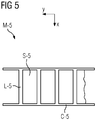
Fig. 5 a schematic view of an example of a anti-scatter grid.
Das in
Die Nut-Paare NP sind entlang der durchgehenden Öffnung H nebeneinander derart angeordnet, dass sie sich in verschiedenen Ebenen E befinden, welche jeweils den Fokuspunkt T aufweisen und sich in der Fokuslinie TL schneiden. Die Nut-Paare NP weisen jeweils eine erste Nut N1 und eine der ersten Nut N1 in Bezug auf die durchgehende Öffnung H gegenüberliegende zweite Nut N2 auf. Die erste Nut N1 und die zweite Nut N2 sind derart ausgebildet, dass ein Lamellenblech L an zwei einander gegenüberliegenden Rändern des Lamellenblechs L in die erste Nut N1 und die zweite Nut N2 aufnehmbar und entlang der ersten Nut N1 und der zweiten Nut N2 in die durchgehende Öffnung H einführbar ist.The groove pairs NP are arranged side by side along the through hole H so as to be in different planes E each having the focal point T and intersecting in the focus line TL. The groove pairs NP each have a first groove N1 and a second groove N2 opposite to the first groove N1 with respect to the through hole H. The first groove N1 and the second groove N2 are formed such that a lamination sheet L is receivable at two opposite edges of the lamination sheet L in the first groove N1 and the second groove N2 and along the first groove N1 and the second groove N2 in the continuous one Opening H is insertable.
Die durchgehende Öffnung H ist im Wesentlichen rechteckig. Die durchgehende Öffnung H weist zwei lange Seiten HL1, HL2 und zwei kurze Seiten HS1, HS2 auf. Der Rahmen R weist einen ersten Querbalken RL1 auf, welcher eine erste lange Seite HL1 der durchgehenden Öffnung H bildet. Der Rahmen R weist einen zweiten Querbalken RL2 auf, welcher eine zweite lange Seite HL2 der durchgehenden Öffnung H bildet. Der Rahmen R weist ein erstes Seitenteil RS1 auf, welches eine erste kurze Seite HS1 der durchgehenden Öffnung H bildet. Der Rahmen R weist ein zweites Seitenteil RS2 auf, welches eine zweite kurze Seite HS2 der durchgehenden Öffnung H bildet. Der erste Querbalken RL1 ist mittels des ersten Seitenteils RS1 und des zweiten Seitenteils RS2 mit dem zweiten Querbalken RL2 verbunden und in einem vorgegebenen Abstand ZR relativ zu dem zweiten Querbalken RL2 angeordnet.The continuous opening H is substantially rectangular. The continuous opening H has two long sides HL1, HL2 and two short sides HS1, HS2. The frame R has a first cross bar RL1, which forms a first long side HL1 of the through hole H. The frame R has a second cross bar RL2, which forms a second long side HL2 of the through opening H. The frame R has a first side part RS1, which forms a first short side HS1 of the continuous opening H. The frame R has a second side part RS2, which forms a second short side HS2 of the continuous opening H. The first transverse bar RL1 is connected to the second transverse bar RL2 by means of the first side part RS1 and the second side part RS2 and arranged at a predetermined distance ZR relative to the second transverse bar RL2.
Das Fokussierungsmodul M weist ferner eine erste Führungsschiene RN1 und eine zweite Führungsschiene RN2 auf. Die jeweils ersten Nuten N1 der Nut-Paare NP sind in der ersten Führungsschiene RN1 ausgebildet. Die jeweils zweiten Nuten N2 der Nut-Paare NP sind in der zweiten Führungsschiene RN2 ausgebildet.The focusing module M further comprises a first guide rail RN1 and a second guide rail RN2. The respective first grooves N1 of the groove pairs NP are formed in the first guide rail RN1. The respective second grooves N2 of the groove pairs NP are formed in the second guide rail RN2.
In dem in
Eine zu dem in
Die Ausrichtung der ersten Nut N1 in der Führungsschiene RN1 entspricht der Fokussierungsrichtung des Lamellenblechs L, welche in die erste Nut N1 eingeführt ist. Die Breite und Höhe der ersten Nut N1 ist einheitlich entsprechend der Abmessungen und Toleranzen des Lamellenblechs L. Entsprechendes gilt für die zweite Nut N2 in der zweiten Führungsschiene RN2.The orientation of the first groove N1 in the guide rail RN1 corresponds to the focusing direction of the lamination sheet L inserted in the first groove N1. The width and height of the first groove N1 is uniform according to the dimensions and tolerances of the lamination plate L. The same applies to the second groove N2 in the second guide rail RN2.
Das in der
In einem Bereich der ersten Nut N1 ist ein erstes Anschlagmittel B1 ausgebildet, wobei das Lamellenblech L entlang der ersten Nut N1 bis zu einem Formschluss des Lamellenblechs L mit dem ersten Anschlagmittel B1 einführbar ist, wobei der Formschluss des Lamellenblechs L mit dem ersten Anschlagmittel B1 einem weiteren Einführen des Lamellenblechs L entlang der ersten Nut N1 entgegenwirkt. In dem in
Insbesondere ist die erste Nut N1 lediglich von der vorderen Stirnseite der Führungsschiene RN1 offen, sodass Lamellenbleche L aus dieser Richtung eingesetzt werden können aber auf der Rückseite nicht herausrutschen können. Die Strukturierung der ersten Führungsschiene RN1, durch welche die erste Nut N1 ausgebildet ist, erstreckt sich also nicht über die gesamte Ausdehnung der ersten Führungsschiene RN1 in Richtung der ersten Nut N1. Entsprechendes gilt für die zweite Nut N2.In particular, the first groove N1 is open only from the front end side of the guide rail RN1, so that lamination sheets L can be used from this direction but can not slip out on the back. The structuring of the first guide rail RN1, through which the first groove N1 is formed, thus does not extend over the entire extent of the first guide rail RN1 in the direction of the first groove N1. The same applies to the second groove N2.
Die Länge der Lamellenbleche L entspricht dem Abstand der ersten Führungsschiene RN1 von der zweiten Führungsschiene RN2 abzüglich einer passenden Toleranz. Der Abstand YL zwischen benachbarten Lamellenblechen L kann insbesondere derart gewählt werden, dass die Rasterung des von den Lamellenblechen L gebildeten Lamellenarrays nicht durch die Rasterung des Detektors 28 abgebildet werden kann. Das kann insbesondere mit einer Rasterung des von den Lamellenblechen L gebildeten Lamellenarrays realisiert werden, die feiner ist als die Auflösung des Detektors 28.The length of the lamella plates L corresponds to the distance of the first guide rail RN1 from the second guide rail RN2 less a matching tolerance. The distance YL between adjacent lamella sheets L can be chosen in particular such that the screening of the lamellar arrays formed by the lamination sheets L can not be imaged by the screening of the
Der Abstand YL benachbarter Lamellenbleche voneinander kann beispielsweise zwischen ca. 0,2 und ca. 0,5 Millimetern betragen. In dem in
Die Länge XR der ersten Nut N1 und/oder der zweiten Nut N2 kann beispielsweise ca. 3 Millimeter betragen. Die Ausdehnung des Rahmens R in Richtung der ersten Nut N1 und/oder in Richtung der zweiten Nut N2 kann insbesondere etwas größer sein als die Länge XR. Die Ausdehnung YR des Rahmens R in einer Richtung, entlang welcher die Nut-Paare NP nacheinander in einer Reihe angeordnet sind, kann beispielsweise ca. 140 Millimeter betragen. Der Abstand ZR von der ersten Nut N1 bis zu der zweiten Nut N2 kann beispielsweise ca. 40 Millimeter betragen.The length XR of the first groove N1 and / or the second groove N2 may be, for example, about 3 millimeters. The extent of the frame R in the direction of the first groove N1 and / or in the direction of the second groove N2 may in particular be slightly greater than the length XR. The extent YR of the frame R in a direction along which the groove pairs NP are successively arranged in a row may be about 140 millimeters, for example. The distance ZR from the first groove N1 to the second groove N2 may be, for example, about 40 millimeters.
Dabei können die Toleranzen, insbesondere für die Breite YN und Tiefe ZN, beispielsweise ca. 10 Mikrometer betragen. Der Abstand von dem Fokuspunkt T bis zu der ersten Nut N1 und/oder bis zu der zweiten Nut N2 kann beispielsweise ca. 220 Millimeter betragen.In this case, the tolerances, in particular for the width YN and depth ZN, for example, be about 10 microns. The distance from the focal point T to the first groove N1 and / or to the second groove N2 may be approximately 220 millimeters, for example.
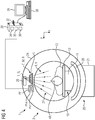
Ohne Beschränkung des allgemeinen Erfindungsgedankens ist für die medizinische Bildgebungsvorrichtung 1 beispielhaft ein Computertomographiegerät gezeigt. Die medizinische Bildgebungsvorrichtung 1 weist die Gantry 20, die tunnelförmige Öffnung 9, die Patientenlagerungsvorrichtung 10 und die Steuerungsvorrichtung 30 auf.Without limiting the general inventive concept, a computed tomography device is shown by way of example for the medical imaging device 1. The medical imaging device 1 has the
Die Gantry 20 weist den stationären Tragrahmen 21 und den Rotor 24 auf. Der Rotor 24 ist mittels einer Drehlagerungsvorrichtung an dem Tragrahmen 21 um eine Rotationsachse AR relativ zu dem Tragrahmen 21 drehbar angeordnet.The
In die tunnelförmige Öffnung 9 ist der Patient 13 einführbar. In der tunnelförmigen Öffnung 9 befindet sich der Akquisitionsbereich 4. In dem Akquisitionsbereich 4 ist ein abzubildender Bereich des Patienten 13 derart positionierbar, dass die Strahlung 27 von der Strahlungsquelle 26 zu dem abzubildenden Bereich gelangen kann und nach einer Wechselwirkung mit dem abzubildenden Bereich zu dem Strahlungsdetektor 28 gelangen kann.In the tunnel-shaped opening 9 of the
Die Patientenlagerungsvorrichtung 10 weist den Lagerungssockel 11 und die Lagerungsplatte 12 zur Lagerung des Patienten 13 auf. Die Lagerungsplatte 12 ist derart relativ zu dem Lagerungssockel 11 bewegbar an dem Lagerungssockel 11 angeordnet, dass die Lagerungsplatte 12 in einer Längsrichtung der Lagerungsplatte 12, insbesondere entlang der Rotationsachse AR, in den Akquisitionsbereich 4 einführbar ist.The
Die medizinische Bildgebungsvorrichtung 1 ist zur Akquisition von Akquisitionsdaten basierend auf einer elektromagnetischen Strahlung 27 ausgebildet. Die medizinische Bildgebungsvorrichtung 1 weist eine Akquisitionseinheit auf. Die Akquisitionseinheit ist eine Projektionsdaten-Akquisitionseinheit mit der Strahlungsquelle 26, z. B. einer Röntgenquelle, und dem Detektor 28, z. B. einem Röntgendetektor, insbesondere einem energieauflösenden Röntgendetektor.The medical imaging device 1 is configured to acquire acquisition data based on
Die Strahlungsquelle 26 ist an dem Rotor 24 angeordnet und zur Emission einer Strahlung 27, z. B. einer Röntgenstrahlung, mit Strahlungsquanten 27 ausgebildet. Der Detektor 28 ist an dem Rotor 24 angeordnet und zur Detektion der Strahlungsquanten 27 ausgebildet. Die Strahlungsquanten 27 können von der Strahlungsquelle 26 zu dem abzubildenden Bereich des Patienten 13 gelangen und nach einer Wechselwirkung mit dem abzubildenden Bereich auf den Detektor 28 auftreffen. Auf diese Weise können mittels der Akquisitionseinheit Akquisitionsdaten des abzubildenden Bereichs in Form von Projektionsdaten erfasst werden.The
Die Steuerungsvorrichtung 30 ist zum Empfangen der von der Akquisitionseinheit akquirierten Akquisitionsdaten ausgebildet. Die Steuerungsvorrichtung 30 ist zum Steuern der medizinischen Bildgebungsvorrichtung 1 ausgebildet. Die Steuerungsvorrichtung 30 weist die Datenverarbeitungseinheit 35, das computerlesbare Medium 32 und das Prozessorsystem 36 auf. Die Steuerungsvorrichtung 30, insbesondere die Datenverarbeitungseinheit 35, wird von einem Datenverarbeitungssystem, welches einen Computer mit einem Prozessorsystem aufweist, gebildet. Die Datenverarbeitungseinheit 35 ist insbesondere zum Steuern der Positioniereinheit PF ausgebildet und mittels der Positionierungsschnittstelle PFI mit der Positioniereinheit PF verbunden.The
Die Steuerungsvorrichtung 30 weist die Bildrekonstruktionseinrichtung 34 auf. Mittels der Bildrekonstruktionseinrichtung 34 kann basierend auf den Akquisitionsdaten ein medizinischer Bilddatensatz rekonstruiert werden.The
Die medizinische Bildgebungsvorrichtung 1 weist eine Eingabevorrichtung 38 und eine Ausgabevorrichtung 39 auf, welche jeweils mit der Steuerungsvorrichtung 30 verbunden sind. Die Eingabevorrichtung 38 ist zum Eingeben von Steuerungs-Informationen, z. B. Bildrekonstruktionsparametern, Untersuchungsparametern oder ähnliches, ausgebildet. Die Ausgabevorrichtung 39 ist insbesondere zum Ausgeben von Steuerungs-Informationen, Bildern und/oder akustischen Signalen ausgebildet.The medical imaging device 1 has an
Die Teile des Rahmens R, welche die Lamellenbleche L in ihrer jeweiligen Position halten und die Ausrichtung der Lamellenbleche L vorgeben, sind derart außerhalb des Strahlengangs angeordnet, dass der Röntgenstrahl 27 durch diese Teile des Rahmens R nicht gestört wird. Insbesondere die Querbalken RL1, RL2 können daher massiv und mechanisch stabil ausgebildet werden, ohne dass dadurch Nachteile in Bezug auf den Röntgenstrahl 27 entstehen. Die Seitenteile RS1, RS2 geben den Abstand der Querbalken RL1, RL2 vor, sodass diese nicht in den Röntgenstrahl 27 hineinragen. Außer den Lamellenblechen L und Luft befindet sich somit kein weiteres Material im Strahlengang, das den Röntgenstrahl 27 beispielsweise durch Streuung oder Absorption beeinflussen könnte.The parts of the frame R, which hold the lamellar sheets L in their respective position and the orientation of the lamellae L predetermine, are arranged outside the beam path, that the
Ferner können an dem Rahmen R, insbesondere in den Querbalken RL1, RL2, Bohrungen RCS, RCM, beispielsweise mit Gewinden, vorgesehen sein. Beispielsweise können mittels der Bohrungen RCS die verschiedenen Teile des Rahmens R, insbesondere die Querbalken RL1, RL2 und die Seitenteile RS1, RS2, miteinander verbunden werden. Beispielsweise kann mittels der Bohrungen RCM der Rahmen R mit einem Aktor PFA der Positioniereinheit PF verbunden werden.Further, on the frame R, in particular in the crossbar RL1, RL2, holes RCS, RCM, for example, with threads, can be provided. For example, the various parts of the frame R, in particular the transverse beams RL1, RL2 and the side parts RS1, RS2, can be connected to one another by means of the bores RCS. For example, by means of the holes RCM, the frame R can be connected to an actuator PFA of the positioning unit PF.
Der Rahmen R kann derart mechanisch stabil ausgebildet werden, dass der Rahmen R relativ hohe Kräfte und Drehmomente aufnehmen kann, ohne beschädigt oder signifikant verformt zu werden. Insbesondere können damit Drehungen des Rahmens R relativ zu der Röntgenquelle 26 durchgeführt werden, ohne die sensiblen und präzisen Führungsschienen RN1, RN2 zu beschädigen. Die Lamellenbleche L sind in dem stabilen Rahmen R fixiert und geschützt. Starke Beschleunigungskräfte durch eine Rotation des Rotors 24 werden von dem Rahmen R aufgenommen und abgeleitet. Damit kann insbesondere verhindert werden, dass durch die Beschleunigungskräfte, welche auf Grund der Rotation des Rotors 24 auftreten, die relative Lage und Position der Lamellenbleche L zueinander verändert wird.The frame R can be made mechanically stable such that the frame R can absorb relatively high forces and torques without being damaged or significantly deformed. In particular, rotations of the frame R relative to the
Die Lamellenbleche L in dem Formfilter F sind so ausgerichtet und fixiert, dass jedes Lamellenblech L auf den Fokuspunkt T und/oder die Fokuslinie TL exakt ausgerichtet ist. Die Lamellenbleche L sind in dem Strahlengang des fächerförmigen Röntgenstrahls 27 positioniert.The lamellar sheets L in the mold filter F are aligned and fixed so that each lamination sheet L is exactly aligned with the focal point T and / or the focus line TL. The lamination sheets L are positioned in the beam path of the fan-shaped
In dem Betriebszustand der medizinischen Bildgebungsvorrichtung, der in der
Mittels der Positioniereinheit PF kann der Formfilter F relativ zu der Röntgenquelle 26 positioniert werden. Insbesondere kann der Formfilter F mittels der Positioniereinheit PF um eine Achse, die zu der Rotationsachse AR im Wesentlichen parallel ist und beispielsweise durch den Formfilter 26 verläuft, gedreht werden. Alternativ oder zusätzlich dazu kann der Formfilter F mittels der Positioniereinheit PF um eine Achse, die sowohl zu der Rotationsachse AR als auch zu einem auf den Detektor 28 auftreffenden linienförmigen Teilstrahl des Röntgenstrahls 27 senkrecht ist und beispielsweise durch den Formfilter 26 verläuft, gedreht werden.By means of the positioning unit PF, the shaping filter F can be positioned relative to the
Alternativ oder zusätzlich dazu kann der Formfilter F relativ zu der Röntgenquelle 26 verschoben werden. Beispielsweise kann der Formfilter F entlang eines auf den Detektor 28 auftreffenden linienförmigen Teilstrahls des Röntgenstrahls 27 und/oder senkrecht zu diesem Teilstrahl verschoben werden, insbesondere im Wesentlichen senkrecht zu der Rotationsachse AR verschoben werden.Alternatively or additionally, the shape filter F can be displaced relative to the
Durch eine Entfernung des Fokuspunkts T von dem Anfangspunkt des Röntgenstrahls 27 kann der Anteil derjenigen linienförmigen Teilstrahlen des fächerförmigen Röntgenstrahls 27, welche auf die Lamellenbleche L treffen und damit absorbiert werden, erhöht werden.By removing the focal point T from the starting point of the
Auf diese Weise kann eine räumliche Intensitätsverteilung des Röntgenstrahls 27 eingestellt werden. Eine Lage- und/oder Positionsveränderung der Lamellenbleche L relativ zu dem Rahmen R würde insbesondere das am Detektor 28 detektierte Signal und die Reproduzierbarkeit von Untersuchungen beeinflussen. Die Erfindung ermöglicht insbesondere ein präzises und dauerhaftes Anordnen von Lamellenblechen L in der jeweiligen Ebene E.In this way, a spatial intensity distribution of the
Die Positioniereinheit PF kann beispielsweise eine kardanische Aufhängung aufweisen. Insbesondere kann der Formfilter F mittels der kardanischen Aufhängung mit dem Rotor 24 verbunden werden und/oder relativ zu der Röntgenquelle 26 positioniert werden.The positioning unit PF can, for example, have a cardan suspension. In particular, the form filter F can be connected to the
Claims (12)
Priority Applications (1)
| Application Number | Priority Date | Filing Date | Title |
|---|---|---|---|
| EP17173761.2A EP3217408B1 (en) | 2017-05-31 | 2017-05-31 | Focussing module for a form filter and form filter for adjusting a spatial intensity distribution of a x-ray beam |
Applications Claiming Priority (1)
| Application Number | Priority Date | Filing Date | Title |
|---|---|---|---|
| EP17173761.2A EP3217408B1 (en) | 2017-05-31 | 2017-05-31 | Focussing module for a form filter and form filter for adjusting a spatial intensity distribution of a x-ray beam |
Publications (3)
| Publication Number | Publication Date |
|---|---|
| EP3217408A2 true EP3217408A2 (en) | 2017-09-13 |
| EP3217408A3 EP3217408A3 (en) | 2017-12-27 |
| EP3217408B1 EP3217408B1 (en) | 2021-07-21 |
Family
ID=59034446
Family Applications (1)
| Application Number | Title | Priority Date | Filing Date |
|---|---|---|---|
| EP17173761.2A Active EP3217408B1 (en) | 2017-05-31 | 2017-05-31 | Focussing module for a form filter and form filter for adjusting a spatial intensity distribution of a x-ray beam |
Country Status (1)
| Country | Link |
|---|---|
| EP (1) | EP3217408B1 (en) |
Cited By (2)
| Publication number | Priority date | Publication date | Assignee | Title |
|---|---|---|---|---|
| EP3598949A1 (en) | 2018-07-27 | 2020-01-29 | Siemens Healthcare GmbH | Computed tomography apparatus comprising lamellae form filter and spring focus x-ray source |
| US11234662B2 (en) | 2018-02-26 | 2022-02-01 | Siemens Healthcare Gmbh | Method and device for changing the spatial intensity distribution of an x-ray beam |
Citations (3)
| Publication number | Priority date | Publication date | Assignee | Title |
|---|---|---|---|---|
| US7403597B2 (en) | 2005-04-22 | 2008-07-22 | Siemens Aktiengesellschaft | Radiation diaphragm in device having two diaphragms, and method for scanning a subject therewith |
| US8218721B2 (en) | 2008-09-30 | 2012-07-10 | Siemens Aktiengesellschaft | X-ray beam modifying diaphragm and diaphragm device |
| US8873704B2 (en) | 2011-02-25 | 2014-10-28 | Siemens Aktiengesellschaft | Filter for an X-ray device, and X-ray device embodying such a filter |
Family Cites Families (6)
| Publication number | Priority date | Publication date | Assignee | Title |
|---|---|---|---|---|
| JPS58114800U (en) * | 1982-01-29 | 1983-08-05 | 株式会社島津製作所 | collimator |
| JPH03120500A (en) * | 1989-10-04 | 1991-05-22 | Toshiba Corp | Porous collimator and its manufacture |
| JP4874755B2 (en) * | 2006-09-29 | 2012-02-15 | 富士フイルム株式会社 | Radiation imaging equipment |
| JP5383266B2 (en) * | 2009-03-19 | 2014-01-08 | ジーイー・メディカル・システムズ・グローバル・テクノロジー・カンパニー・エルエルシー | Collimator unit, radiation detection apparatus, and radiation diagnostic apparatus |
| JP5610461B2 (en) * | 2009-10-23 | 2014-10-22 | ジーイー・メディカル・システムズ・グローバル・テクノロジー・カンパニー・エルエルシー | Collimator module, X-ray detector and X-ray CT apparatus |
| US10082473B2 (en) * | 2015-07-07 | 2018-09-25 | General Electric Company | X-ray filtration |
-
2017
- 2017-05-31 EP EP17173761.2A patent/EP3217408B1/en active Active
Patent Citations (3)
| Publication number | Priority date | Publication date | Assignee | Title |
|---|---|---|---|---|
| US7403597B2 (en) | 2005-04-22 | 2008-07-22 | Siemens Aktiengesellschaft | Radiation diaphragm in device having two diaphragms, and method for scanning a subject therewith |
| US8218721B2 (en) | 2008-09-30 | 2012-07-10 | Siemens Aktiengesellschaft | X-ray beam modifying diaphragm and diaphragm device |
| US8873704B2 (en) | 2011-02-25 | 2014-10-28 | Siemens Aktiengesellschaft | Filter for an X-ray device, and X-ray device embodying such a filter |
Cited By (2)
| Publication number | Priority date | Publication date | Assignee | Title |
|---|---|---|---|---|
| US11234662B2 (en) | 2018-02-26 | 2022-02-01 | Siemens Healthcare Gmbh | Method and device for changing the spatial intensity distribution of an x-ray beam |
| EP3598949A1 (en) | 2018-07-27 | 2020-01-29 | Siemens Healthcare GmbH | Computed tomography apparatus comprising lamellae form filter and spring focus x-ray source |
Also Published As
| Publication number | Publication date |
|---|---|
| EP3217408B1 (en) | 2021-07-21 |
| EP3217408A3 (en) | 2017-12-27 |
Similar Documents
| Publication | Publication Date | Title |
|---|---|---|
| DE102010062192B3 (en) | 2D collimator for a radiation detector and method of making such a 2D collimator | |
| EP1089297B1 (en) | Grid for X-ray absorption | |
| DE102005010077B4 (en) | Detector with a scintillator and imaging device, comprising such a detector | |
| EP1107260B1 (en) | X-ray absorbing grid | |
| DE112005001757B4 (en) | X-ray device with a single-sheet X-ray collimator | |
| EP2849649B1 (en) | X-ray detector with manipulation unit for movement of detector modules on a circle | |
| DE602004012080T2 (en) | IDENTIFYING IONIZING RADIATION TO DUAL ENERGY SCANNING BASIS | |
| EP1691216B1 (en) | Radiography system and method for recording X-Ray exposures on photostimulable sheets | |
| DE102010011581A1 (en) | Method for producing a 2D collimator element for a radiation detector and 2D collimator element | |
| DE10358866A1 (en) | Cast collimators for CT detectors and processes for their manufacture | |
| EP1691217B1 (en) | Method and device for reading X-ray exposures stored in a storage phosphor layer | |
| DE102012101568A1 (en) | Two-dimensional collimator module, X-ray detector and X-ray CT apparatus | |
| EP1691215B1 (en) | Method and device for reading X-Ray exposures stored in storage phosphor layers | |
| DE102010062133A1 (en) | Collimator for a radiation detector and method for producing such a collimator and method for producing a beam detector having collimators | |
| DE102005049228A1 (en) | Detector used in X-ray computer tomography devices comprises an array of photodiodes in which each photodiode is divided into sub-photodiodes each having an electric switch | |
| DE102012105220A1 (en) | Collimation method and apparatus for detectors | |
| DE102012214387A1 (en) | X-ray detector and method for operating an X-ray detector | |
| DE102014218462A1 (en) | Method for producing a collimator module and method for producing a collimator bridge as well as collimator module, collimator bridge, collimator and tomography device | |
| DE102008061487A1 (en) | Method for producing a comb-like collimator element for a collimator arrangement and collimator element | |
| DE102018214311A1 (en) | Device for changing a spatial intensity distribution of an X-ray beam | |
| EP3217408B1 (en) | Focussing module for a form filter and form filter for adjusting a spatial intensity distribution of a x-ray beam | |
| DE2548531C2 (en) | ||
| DE102014217569B4 (en) | Collimator module, detector module and method for manufacturing a collimator module | |
| DE102008030893A1 (en) | Stray radiation collimator for use in radiation detector, has group of absorber elements arranged in collimation direction and another group of another absorber elements arranged in another collimation direction | |
| CH630176A5 (en) | Method of producing a tomogram and device for tomographically investigating an object |
Legal Events
| Date | Code | Title | Description |
|---|---|---|---|
| PUAI | Public reference made under article 153(3) epc to a published international application that has entered the european phase |
Free format text: ORIGINAL CODE: 0009012 |
|
| STAA | Information on the status of an ep patent application or granted ep patent |
Free format text: STATUS: THE APPLICATION HAS BEEN PUBLISHED |
|
| AK | Designated contracting states |
Kind code of ref document: A2 Designated state(s): AL AT BE BG CH CY CZ DE DK EE ES FI FR GB GR HR HU IE IS IT LI LT LU LV MC MK MT NL NO PL PT RO RS SE SI SK SM TR |
|
| AX | Request for extension of the european patent |
Extension state: BA ME |
|
| PUAL | Search report despatched |
Free format text: ORIGINAL CODE: 0009013 |
|
| AK | Designated contracting states |
Kind code of ref document: A3 Designated state(s): AL AT BE BG CH CY CZ DE DK EE ES FI FR GB GR HR HU IE IS IT LI LT LU LV MC MK MT NL NO PL PT RO RS SE SI SK SM TR |
|
| AX | Request for extension of the european patent |
Extension state: BA ME |
|
| RIC1 | Information provided on ipc code assigned before grant |
Ipc: G21K 1/10 20060101ALI20171121BHEP Ipc: G21K 1/02 20060101AFI20171121BHEP |
|
| STAA | Information on the status of an ep patent application or granted ep patent |
Free format text: STATUS: REQUEST FOR EXAMINATION WAS MADE |
|
| 17P | Request for examination filed |
Effective date: 20180205 |
|
| RBV | Designated contracting states (corrected) |
Designated state(s): AL AT BE BG CH CY CZ DE DK EE ES FI FR GB GR HR HU IE IS IT LI LT LU LV MC MK MT NL NO PL PT RO RS SE SI SK SM TR |
|
| GRAP | Despatch of communication of intention to grant a patent |
Free format text: ORIGINAL CODE: EPIDOSNIGR1 |
|
| STAA | Information on the status of an ep patent application or granted ep patent |
Free format text: STATUS: GRANT OF PATENT IS INTENDED |
|
| INTG | Intention to grant announced |
Effective date: 20210401 |
|
| GRAS | Grant fee paid |
Free format text: ORIGINAL CODE: EPIDOSNIGR3 |
|
| GRAA | (expected) grant |
Free format text: ORIGINAL CODE: 0009210 |
|
| STAA | Information on the status of an ep patent application or granted ep patent |
Free format text: STATUS: THE PATENT HAS BEEN GRANTED |
|
| AK | Designated contracting states |
Kind code of ref document: B1 Designated state(s): AL AT BE BG CH CY CZ DE DK EE ES FI FR GB GR HR HU IE IS IT LI LT LU LV MC MK MT NL NO PL PT RO RS SE SI SK SM TR |
|
| REG | Reference to a national code |
Ref country code: GB Ref legal event code: FG4D Free format text: NOT ENGLISH |
|
| REG | Reference to a national code |
Ref country code: CH Ref legal event code: EP |
|
| REG | Reference to a national code |
Ref country code: DE Ref legal event code: R096 Ref document number: 502017010941 Country of ref document: DE |
|
| REG | Reference to a national code |
Ref country code: AT Ref legal event code: REF Ref document number: 1413353 Country of ref document: AT Kind code of ref document: T Effective date: 20210815 |
|
| REG | Reference to a national code |
Ref country code: IE Ref legal event code: FG4D Free format text: LANGUAGE OF EP DOCUMENT: GERMAN |
|
| REG | Reference to a national code |
Ref country code: LT Ref legal event code: MG9D |
|
| REG | Reference to a national code |
Ref country code: NL Ref legal event code: MP Effective date: 20210721 |
|
| PG25 | Lapsed in a contracting state [announced via postgrant information from national office to epo] |
Ref country code: RS Free format text: LAPSE BECAUSE OF FAILURE TO SUBMIT A TRANSLATION OF THE DESCRIPTION OR TO PAY THE FEE WITHIN THE PRESCRIBED TIME-LIMIT Effective date: 20210721 Ref country code: SE Free format text: LAPSE BECAUSE OF FAILURE TO SUBMIT A TRANSLATION OF THE DESCRIPTION OR TO PAY THE FEE WITHIN THE PRESCRIBED TIME-LIMIT Effective date: 20210721 Ref country code: LT Free format text: LAPSE BECAUSE OF FAILURE TO SUBMIT A TRANSLATION OF THE DESCRIPTION OR TO PAY THE FEE WITHIN THE PRESCRIBED TIME-LIMIT Effective date: 20210721 Ref country code: BG Free format text: LAPSE BECAUSE OF FAILURE TO SUBMIT A TRANSLATION OF THE DESCRIPTION OR TO PAY THE FEE WITHIN THE PRESCRIBED TIME-LIMIT Effective date: 20211021 Ref country code: PT Free format text: LAPSE BECAUSE OF FAILURE TO SUBMIT A TRANSLATION OF THE DESCRIPTION OR TO PAY THE FEE WITHIN THE PRESCRIBED TIME-LIMIT Effective date: 20211122 Ref country code: NO Free format text: LAPSE BECAUSE OF FAILURE TO SUBMIT A TRANSLATION OF THE DESCRIPTION OR TO PAY THE FEE WITHIN THE PRESCRIBED TIME-LIMIT Effective date: 20211021 Ref country code: NL Free format text: LAPSE BECAUSE OF FAILURE TO SUBMIT A TRANSLATION OF THE DESCRIPTION OR TO PAY THE FEE WITHIN THE PRESCRIBED TIME-LIMIT Effective date: 20210721 Ref country code: HR Free format text: LAPSE BECAUSE OF FAILURE TO SUBMIT A TRANSLATION OF THE DESCRIPTION OR TO PAY THE FEE WITHIN THE PRESCRIBED TIME-LIMIT Effective date: 20210721 Ref country code: ES Free format text: LAPSE BECAUSE OF FAILURE TO SUBMIT A TRANSLATION OF THE DESCRIPTION OR TO PAY THE FEE WITHIN THE PRESCRIBED TIME-LIMIT Effective date: 20210721 Ref country code: FI Free format text: LAPSE BECAUSE OF FAILURE TO SUBMIT A TRANSLATION OF THE DESCRIPTION OR TO PAY THE FEE WITHIN THE PRESCRIBED TIME-LIMIT Effective date: 20210721 |
|
| PG25 | Lapsed in a contracting state [announced via postgrant information from national office to epo] |
Ref country code: PL Free format text: LAPSE BECAUSE OF FAILURE TO SUBMIT A TRANSLATION OF THE DESCRIPTION OR TO PAY THE FEE WITHIN THE PRESCRIBED TIME-LIMIT Effective date: 20210721 Ref country code: LV Free format text: LAPSE BECAUSE OF FAILURE TO SUBMIT A TRANSLATION OF THE DESCRIPTION OR TO PAY THE FEE WITHIN THE PRESCRIBED TIME-LIMIT Effective date: 20210721 Ref country code: GR Free format text: LAPSE BECAUSE OF FAILURE TO SUBMIT A TRANSLATION OF THE DESCRIPTION OR TO PAY THE FEE WITHIN THE PRESCRIBED TIME-LIMIT Effective date: 20211022 |
|
| REG | Reference to a national code |
Ref country code: DE Ref legal event code: R097 Ref document number: 502017010941 Country of ref document: DE |
|
| PG25 | Lapsed in a contracting state [announced via postgrant information from national office to epo] |
Ref country code: DK Free format text: LAPSE BECAUSE OF FAILURE TO SUBMIT A TRANSLATION OF THE DESCRIPTION OR TO PAY THE FEE WITHIN THE PRESCRIBED TIME-LIMIT Effective date: 20210721 |
|
| PLBE | No opposition filed within time limit |
Free format text: ORIGINAL CODE: 0009261 |
|
| STAA | Information on the status of an ep patent application or granted ep patent |
Free format text: STATUS: NO OPPOSITION FILED WITHIN TIME LIMIT |
|
| PG25 | Lapsed in a contracting state [announced via postgrant information from national office to epo] |
Ref country code: SM Free format text: LAPSE BECAUSE OF FAILURE TO SUBMIT A TRANSLATION OF THE DESCRIPTION OR TO PAY THE FEE WITHIN THE PRESCRIBED TIME-LIMIT Effective date: 20210721 Ref country code: SK Free format text: LAPSE BECAUSE OF FAILURE TO SUBMIT A TRANSLATION OF THE DESCRIPTION OR TO PAY THE FEE WITHIN THE PRESCRIBED TIME-LIMIT Effective date: 20210721 Ref country code: RO Free format text: LAPSE BECAUSE OF FAILURE TO SUBMIT A TRANSLATION OF THE DESCRIPTION OR TO PAY THE FEE WITHIN THE PRESCRIBED TIME-LIMIT Effective date: 20210721 Ref country code: EE Free format text: LAPSE BECAUSE OF FAILURE TO SUBMIT A TRANSLATION OF THE DESCRIPTION OR TO PAY THE FEE WITHIN THE PRESCRIBED TIME-LIMIT Effective date: 20210721 Ref country code: CZ Free format text: LAPSE BECAUSE OF FAILURE TO SUBMIT A TRANSLATION OF THE DESCRIPTION OR TO PAY THE FEE WITHIN THE PRESCRIBED TIME-LIMIT Effective date: 20210721 Ref country code: AL Free format text: LAPSE BECAUSE OF FAILURE TO SUBMIT A TRANSLATION OF THE DESCRIPTION OR TO PAY THE FEE WITHIN THE PRESCRIBED TIME-LIMIT Effective date: 20210721 |
|
| 26N | No opposition filed |
Effective date: 20220422 |
|
| PG25 | Lapsed in a contracting state [announced via postgrant information from national office to epo] |
Ref country code: IT Free format text: LAPSE BECAUSE OF FAILURE TO SUBMIT A TRANSLATION OF THE DESCRIPTION OR TO PAY THE FEE WITHIN THE PRESCRIBED TIME-LIMIT Effective date: 20210721 |
|
| REG | Reference to a national code |
Ref country code: CH Ref legal event code: PL |
|
| REG | Reference to a national code |
Ref country code: BE Ref legal event code: MM Effective date: 20220531 |
|
| PG25 | Lapsed in a contracting state [announced via postgrant information from national office to epo] |
Ref country code: MC Free format text: LAPSE BECAUSE OF FAILURE TO SUBMIT A TRANSLATION OF THE DESCRIPTION OR TO PAY THE FEE WITHIN THE PRESCRIBED TIME-LIMIT Effective date: 20210721 Ref country code: LU Free format text: LAPSE BECAUSE OF NON-PAYMENT OF DUE FEES Effective date: 20220531 Ref country code: LI Free format text: LAPSE BECAUSE OF NON-PAYMENT OF DUE FEES Effective date: 20220531 Ref country code: CH Free format text: LAPSE BECAUSE OF NON-PAYMENT OF DUE FEES Effective date: 20220531 |
|
| PG25 | Lapsed in a contracting state [announced via postgrant information from national office to epo] |
Ref country code: IE Free format text: LAPSE BECAUSE OF NON-PAYMENT OF DUE FEES Effective date: 20220531 |
|
| PG25 | Lapsed in a contracting state [announced via postgrant information from national office to epo] |
Ref country code: BE Free format text: LAPSE BECAUSE OF NON-PAYMENT OF DUE FEES Effective date: 20220531 |
|
| REG | Reference to a national code |
Ref country code: AT Ref legal event code: MM01 Ref document number: 1413353 Country of ref document: AT Kind code of ref document: T Effective date: 20220531 |
|
| PG25 | Lapsed in a contracting state [announced via postgrant information from national office to epo] |
Ref country code: AT Free format text: LAPSE BECAUSE OF NON-PAYMENT OF DUE FEES Effective date: 20220531 |
|
| PGFP | Annual fee paid to national office [announced via postgrant information from national office to epo] |
Ref country code: FR Payment date: 20230515 Year of fee payment: 7 Ref country code: DE Payment date: 20220620 Year of fee payment: 7 |
|
| PGFP | Annual fee paid to national office [announced via postgrant information from national office to epo] |
Ref country code: GB Payment date: 20230605 Year of fee payment: 7 |
|
| REG | Reference to a national code |
Ref country code: DE Ref legal event code: R081 Ref document number: 502017010941 Country of ref document: DE Owner name: SIEMENS HEALTHINEERS AG, DE Free format text: FORMER OWNER: SIEMENS HEALTHCARE GMBH, MUENCHEN, DE |
|
| PG25 | Lapsed in a contracting state [announced via postgrant information from national office to epo] |
Ref country code: HU Free format text: LAPSE BECAUSE OF FAILURE TO SUBMIT A TRANSLATION OF THE DESCRIPTION OR TO PAY THE FEE WITHIN THE PRESCRIBED TIME-LIMIT; INVALID AB INITIO Effective date: 20170531 |