EP3217208A1 - Head device of three-dimensional modeling equipment having unidirectionally rotating polygon mirrors, scanning method for modeling plane using same, and three-dimensional modeling device using same - Google Patents
Head device of three-dimensional modeling equipment having unidirectionally rotating polygon mirrors, scanning method for modeling plane using same, and three-dimensional modeling device using same Download PDFInfo
- Publication number
- EP3217208A1 EP3217208A1 EP14904146.9A EP14904146A EP3217208A1 EP 3217208 A1 EP3217208 A1 EP 3217208A1 EP 14904146 A EP14904146 A EP 14904146A EP 3217208 A1 EP3217208 A1 EP 3217208A1
- Authority
- EP
- European Patent Office
- Prior art keywords
- modeling
- polygon mirror
- axis
- light guide
- plane
- Prior art date
- Legal status (The legal status is an assumption and is not a legal conclusion. Google has not performed a legal analysis and makes no representation as to the accuracy of the status listed.)
- Granted
Links
- 238000000034 method Methods 0.000 title claims abstract description 93
- 230000005855 radiation Effects 0.000 claims description 41
- 238000006073 displacement reaction Methods 0.000 claims description 21
- 239000000463 material Substances 0.000 claims description 15
- 238000012937 correction Methods 0.000 claims description 8
- 230000008569 process Effects 0.000 description 14
- 230000009471 action Effects 0.000 description 10
- 238000001723 curing Methods 0.000 description 10
- 238000012545 processing Methods 0.000 description 10
- 238000005245 sintering Methods 0.000 description 10
- 230000008901 benefit Effects 0.000 description 7
- 230000008859 change Effects 0.000 description 6
- 230000004044 response Effects 0.000 description 6
- 230000001133 acceleration Effects 0.000 description 5
- 230000000903 blocking effect Effects 0.000 description 5
- 238000004519 manufacturing process Methods 0.000 description 4
- 230000003287 optical effect Effects 0.000 description 4
- 238000010586 diagram Methods 0.000 description 3
- 238000005516 engineering process Methods 0.000 description 3
- 238000000110 selective laser sintering Methods 0.000 description 3
- 238000010146 3D printing Methods 0.000 description 2
- 230000000694 effects Effects 0.000 description 2
- 238000000016 photochemical curing Methods 0.000 description 2
- 238000003491 array Methods 0.000 description 1
- 230000008021 deposition Effects 0.000 description 1
- 238000013461 design Methods 0.000 description 1
- 230000006872 improvement Effects 0.000 description 1
- 238000001459 lithography Methods 0.000 description 1
- 230000004048 modification Effects 0.000 description 1
- 238000012986 modification Methods 0.000 description 1
- 230000010355 oscillation Effects 0.000 description 1
- 239000000843 powder Substances 0.000 description 1
- 238000006467 substitution reaction Methods 0.000 description 1
- 238000005496 tempering Methods 0.000 description 1
Images


Classifications
-
- B—PERFORMING OPERATIONS; TRANSPORTING
- B29—WORKING OF PLASTICS; WORKING OF SUBSTANCES IN A PLASTIC STATE IN GENERAL
- B29C—SHAPING OR JOINING OF PLASTICS; SHAPING OF MATERIAL IN A PLASTIC STATE, NOT OTHERWISE PROVIDED FOR; AFTER-TREATMENT OF THE SHAPED PRODUCTS, e.g. REPAIRING
- B29C67/00—Shaping techniques not covered by groups B29C39/00 - B29C65/00, B29C70/00 or B29C73/00
-
- G—PHYSICS
- G02—OPTICS
- G02B—OPTICAL ELEMENTS, SYSTEMS OR APPARATUS
- G02B26/00—Optical devices or arrangements for the control of light using movable or deformable optical elements
- G02B26/08—Optical devices or arrangements for the control of light using movable or deformable optical elements for controlling the direction of light
- G02B26/10—Scanning systems
- G02B26/12—Scanning systems using multifaceted mirrors
- G02B26/127—Adaptive control of the scanning light beam, e.g. using the feedback from one or more detectors
-
- H—ELECTRICITY
- H04—ELECTRIC COMMUNICATION TECHNIQUE
- H04N—PICTORIAL COMMUNICATION, e.g. TELEVISION
- H04N1/00—Scanning, transmission or reproduction of documents or the like, e.g. facsimile transmission; Details thereof
- H04N1/04—Scanning arrangements, i.e. arrangements for the displacement of active reading or reproducing elements relative to the original or reproducing medium, or vice versa
- H04N1/113—Scanning arrangements, i.e. arrangements for the displacement of active reading or reproducing elements relative to the original or reproducing medium, or vice versa using oscillating or rotating mirrors
-
- B—PERFORMING OPERATIONS; TRANSPORTING
- B29—WORKING OF PLASTICS; WORKING OF SUBSTANCES IN A PLASTIC STATE IN GENERAL
- B29C—SHAPING OR JOINING OF PLASTICS; SHAPING OF MATERIAL IN A PLASTIC STATE, NOT OTHERWISE PROVIDED FOR; AFTER-TREATMENT OF THE SHAPED PRODUCTS, e.g. REPAIRING
- B29C64/00—Additive manufacturing, i.e. manufacturing of three-dimensional [3D] objects by additive deposition, additive agglomeration or additive layering, e.g. by 3D printing, stereolithography or selective laser sintering
- B29C64/20—Apparatus for additive manufacturing; Details thereof or accessories therefor
- B29C64/227—Driving means
- B29C64/241—Driving means for rotary motion
-
- B—PERFORMING OPERATIONS; TRANSPORTING
- B29—WORKING OF PLASTICS; WORKING OF SUBSTANCES IN A PLASTIC STATE IN GENERAL
- B29C—SHAPING OR JOINING OF PLASTICS; SHAPING OF MATERIAL IN A PLASTIC STATE, NOT OTHERWISE PROVIDED FOR; AFTER-TREATMENT OF THE SHAPED PRODUCTS, e.g. REPAIRING
- B29C64/00—Additive manufacturing, i.e. manufacturing of three-dimensional [3D] objects by additive deposition, additive agglomeration or additive layering, e.g. by 3D printing, stereolithography or selective laser sintering
- B29C64/20—Apparatus for additive manufacturing; Details thereof or accessories therefor
- B29C64/264—Arrangements for irradiation
-
- B—PERFORMING OPERATIONS; TRANSPORTING
- B29—WORKING OF PLASTICS; WORKING OF SUBSTANCES IN A PLASTIC STATE IN GENERAL
- B29C—SHAPING OR JOINING OF PLASTICS; SHAPING OF MATERIAL IN A PLASTIC STATE, NOT OTHERWISE PROVIDED FOR; AFTER-TREATMENT OF THE SHAPED PRODUCTS, e.g. REPAIRING
- B29C64/00—Additive manufacturing, i.e. manufacturing of three-dimensional [3D] objects by additive deposition, additive agglomeration or additive layering, e.g. by 3D printing, stereolithography or selective laser sintering
- B29C64/30—Auxiliary operations or equipment
- B29C64/386—Data acquisition or data processing for additive manufacturing
-
- B—PERFORMING OPERATIONS; TRANSPORTING
- B33—ADDITIVE MANUFACTURING TECHNOLOGY
- B33Y—ADDITIVE MANUFACTURING, i.e. MANUFACTURING OF THREE-DIMENSIONAL [3-D] OBJECTS BY ADDITIVE DEPOSITION, ADDITIVE AGGLOMERATION OR ADDITIVE LAYERING, e.g. BY 3-D PRINTING, STEREOLITHOGRAPHY OR SELECTIVE LASER SINTERING
- B33Y30/00—Apparatus for additive manufacturing; Details thereof or accessories therefor
-
- B—PERFORMING OPERATIONS; TRANSPORTING
- B33—ADDITIVE MANUFACTURING TECHNOLOGY
- B33Y—ADDITIVE MANUFACTURING, i.e. MANUFACTURING OF THREE-DIMENSIONAL [3-D] OBJECTS BY ADDITIVE DEPOSITION, ADDITIVE AGGLOMERATION OR ADDITIVE LAYERING, e.g. BY 3-D PRINTING, STEREOLITHOGRAPHY OR SELECTIVE LASER SINTERING
- B33Y50/00—Data acquisition or data processing for additive manufacturing
- B33Y50/02—Data acquisition or data processing for additive manufacturing for controlling or regulating additive manufacturing processes
-
- G—PHYSICS
- G02—OPTICS
- G02B—OPTICAL ELEMENTS, SYSTEMS OR APPARATUS
- G02B26/00—Optical devices or arrangements for the control of light using movable or deformable optical elements
- G02B26/08—Optical devices or arrangements for the control of light using movable or deformable optical elements for controlling the direction of light
- G02B26/10—Scanning systems
- G02B26/101—Scanning systems with both horizontal and vertical deflecting means, e.g. raster or XY scanners
-
- G—PHYSICS
- G02—OPTICS
- G02B—OPTICAL ELEMENTS, SYSTEMS OR APPARATUS
- G02B26/00—Optical devices or arrangements for the control of light using movable or deformable optical elements
- G02B26/08—Optical devices or arrangements for the control of light using movable or deformable optical elements for controlling the direction of light
- G02B26/10—Scanning systems
- G02B26/12—Scanning systems using multifaceted mirrors
-
- G—PHYSICS
- G05—CONTROLLING; REGULATING
- G05B—CONTROL OR REGULATING SYSTEMS IN GENERAL; FUNCTIONAL ELEMENTS OF SUCH SYSTEMS; MONITORING OR TESTING ARRANGEMENTS FOR SUCH SYSTEMS OR ELEMENTS
- G05B19/00—Programme-control systems
- G05B19/02—Programme-control systems electric
- G05B19/18—Numerical control [NC], i.e. automatically operating machines, in particular machine tools, e.g. in a manufacturing environment, so as to execute positioning, movement or co-ordinated operations by means of programme data in numerical form
- G05B19/4097—Numerical control [NC], i.e. automatically operating machines, in particular machine tools, e.g. in a manufacturing environment, so as to execute positioning, movement or co-ordinated operations by means of programme data in numerical form characterised by using design data to control NC machines, e.g. CAD/CAM
- G05B19/4099—Surface or curve machining, making 3D objects, e.g. desktop manufacturing
-
- G—PHYSICS
- G05—CONTROLLING; REGULATING
- G05B—CONTROL OR REGULATING SYSTEMS IN GENERAL; FUNCTIONAL ELEMENTS OF SUCH SYSTEMS; MONITORING OR TESTING ARRANGEMENTS FOR SUCH SYSTEMS OR ELEMENTS
- G05B2219/00—Program-control systems
- G05B2219/30—Nc systems
- G05B2219/49—Nc machine tool, till multiple
- G05B2219/49023—3-D printing, layer of powder, add drops of binder in layer, new powder
Definitions
- the present invention relates to the head apparatus of the three-dimensional modeling equipment and a method for scanning a modeling plane using the same and, more particularly, to the head apparatus of the three-dimensional modeling equipment which has a configuration including polygon mirrors that rotate in one direction, can perform 2-axis scanning at high speed by a combination of the polygon mirrors, can easily control timing and a location to which a modeling beam is radiated, and has an advantage of improving modeling precision, and a method for scanning a modeling plane using the same.
- 3D printing is one of methods for fabricating a product, and has been chiefly used to fabricate a prototype because it has a smaller loss of materials than conventional cutting processing due to the use of a stacking method and it consumes a relatively low production cost.
- a 3D printing method includes methods, such as a stereo lithography apparatus (SLA), selective laser sintering (SLS), and fused deposition modeling (SDM).
- Korean Patent Application Publication No. 1996-0024766 discloses a 3D model forming apparatus, including a controller which corrects a control pulse based on a signal fed back by a motor so that the motor is rotated at a target speed, a motor driver which supplies a driving voltage to the motor0- ⁇ in response to the control pulse output by the controller, a laser oscillation unit which generates a laser beam, and an attenuator which attenuates a laser beam output to the scan lens side in response to the driving voltage, in order to solve a problem in that a model is deformed into an unwanted structure because the radiation time of a laser beam becomes longer than a steady movement section in an acceleration and deceleration section that appears near the driving start point and driving end point of a servo motor with respect to a beam modeling apparatus of an X-Y plotter method.
- the prior art has a first problem in that control precision is deteriorated compared to a method of controlling a beam path because a head directly moves to a beam radiation point through a 2-axis moving rail and radiates a modeling beam, a second problem in that modeling quality is deteriorated because the relatively heavy head is directly moved and vibration is generated due to the acceleration or deceleration of the head, and a third problem in that such a vibration problem becomes further severe when a modeling speed is increased.
- the head in order to implement the radiation of a modeling beam not having an omitted portion with respect to a one modeling plane, the head does not directly move to a modeling portion and does not radiate a modeling beam.
- two sets of optical elements called polygon mirrors are properly arranged in the space, and the angular displacement and angular speed of two polygon mirrors and a modeling beam source unit for generating a modeling beam are controlled so that they operate in conjunction with each other.
- the polygon mirrors are rotated in one direction, a vibration possibility generated due to the stop or acceleration of the polygon mirror and a change in the rotating direction of the polygon mirror can be minimized, and a modeling speed can be increased.
- the modeling beam source unit is controlled or a separate element is introduced in order to correct a difference in the modeling beam output power density in each incident point of a modeling plane and a difference in the path length of a modeling beam.
- the present invention has a first advantage in that the radiation of a modeling beam can be performed at high speed because the polygon mirrors rotating in a single direction are adopted and the polygon mirror continues to rotate without a stop, a second advantage in that vibration and noise generated by the head apparatus can be reduced and thus quality of a modeling layer formed in a modeling plane 10 can be improved because control is performed through control of the rotating angular speed and rotating angular displacement of the two polygon mirrors in controlling the radiation location of a modeling beam, and a third advantage in that modeling quality can be improved by controlling the output value of a modeling beam through a controller or implementing uniform modeling beam output power density with respect to the entire modeling plane 10 by applying a modeling beam incident angle correction unit 50. Furthermore, the present invention may be applied to three-dimensional modeling apparatuses of various methods including the SLA or SLS method.
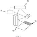
- the head apparatus of three-dimensional modeling equipment may include, in order to implement a function to radiate a modeling beam to the entire surface of a modeling plane 10 perpendicular to a third axis 3 and including a first axis 1 and a second axis 2 in a specific scanning pattern, the first axis 1 and the second axis 2 being perpendicular to each other, a modeling beam source unit 15 which generates the modeling beam, a first light guide unit 20 disposed at a specific location over the modeling plane 10 and having a function to primarily reflect the modeling beam from the modeling beam source unit 15 and to enable the primarily reflected modeling beam to be incident on a second light guide unit 30, the second light guide unit 30 disposed at a specific location over the modeling plane 10 and having a function to secondarily reflect the modeling beam incident from the first light guide unit 20 and to enable the secondarily reflected modeling beam to be incident on the modeling plane 10, and a control unit 40 which turns on or off the modeling beam, adjusts output power of the modeling beam, and
- the head apparatus of the three-dimensional modeling equipment of the present invention may further include a modeling beam incident angle correction unit 50 having a function to enable the modeling beam to be vertically incident on the modeling plane 10 in all of points forming the modeling plane 10.
- control unit 40 may control the pulse amplitude or pulse frequency of the modeling beam in order to correct a difference in the path length which is necessary for the modeling beam to reach each of points forming the modeling plane 10 or a difference in output power density of a modeling beam in each of the points which is caused depending on a difference in the incident angle of the modeling beam.
- control unit 40 may include a first photosensor 41 having a function to determine the start timing of each of a plurality of line scans in a direction parallel to the second axis 2 by sensing a modeling beam incident on a specific point and to synchronize the driving of the modeling beam source unit 15 and the driving of the first light guide unit 20 or the second light guide unit 30.
- control unit 40 may further include a fourth photosensor 44 having a function to determine end timing of each of a plurality of line scans in the direction parallel to the second axis 2 by sensing a modeling beam incident on a specific point and to synchronize the driving of the modeling beam source unit 15 and the driving of the first light guide unit 20 or the second light guide unit 30.
- control unit 40 may include a second photosensor 42 having a function to determine first start timing of the radiation of a modeling beam to the modeling plane 10 by sensing the modeling beam incident on a specific location of the modeling plane 10 and to synchronize the driving of the modeling beam source unit 15 and the driving of the first light guide unit 20 or the second light guide unit 30.
- control unit 40 may further include a third photosensor 43 having a function to determine the final end timing of the radiation of a modeling beam to the modeling plane 10 by sending the modeling beam incident on a specific location of the modeling plane 10.
- the modeling beam may be incident on the first light guide unit 20 while forming a specific angle to the second axis 2.
- the scanning pattern may be a pattern formed as a plurality of line scans having a direction parallel to the second axis 2 is stepped at a specific interval in the direction of the first axis 1.
- the first light guide unit 20 of the head apparatus of the three-dimensional modeling equipment of the present invention may include a first polygon mirror 21.
- the first polygon mirror 21 may be disposed using a fourth axis 4 parallel to the first axis 1 as its rotating central axis.
- the second light guide unit 30 may include a second polygon mirror 31.
- the second polygon mirror 31 may be disposed using a fifth axis 5 parallel to the third axis 3 as its rotating central axis.
- the plurality of line scans in the direction parallel to the second axis 2 may be performed as the first polygon mirror 21 is rotated.
- the stepping at the specific interval in the direction of the first axis 1 may be performed as the second polygon mirror 31 is rotated.
- a method for scanning the modeling plane 10 includes the steps of, first, rotating, by the first polygon mirror 21, in one direction and starting, by the modeling beam source unit 15, to have a modeling beam incident on the first polygon mirror 21; second, enabling a modeling beam primarily reflected by the first polygon mirror 21 to be secondarily reflected by the second polygon mirror 31 and then to perform a line scan on the modeling plane 10 in the direction parallel to the second axis 2 while the first polygon mirror 21 continues to rotate at a specific speed; third, controlling the modeling beam 11 so that the modeling beam 11 is not radiated to the modeling plane 10, thereby terminating the line scan in the step (ii); fourth, rotating, by the second polygon mirror 31, at specific angular displacement and continuing to rotate, by the first polygon mirror 21, in the same rotating direction until a next reflection surface adjacent to a previous reflection surface reaches a specific location in order to perform a next line scan after stepping at a specific interval in the direction of the first axis 1 after the line scan in the second step
- the method for scanning the modeling plane 10 according to the present invention may further include the step of preparing, by the second polygon mirror 31, rotation in the direction identical with the rotating direction in the fifth step after the fifth step.
- the method for scanning the modeling plane 10 according to the present invention may further include the step of preparing, by the second polygon mirror 31, rotation in the direction opposite the rotating direction in the fifth step after the fifth step.
- the rotation of the second polygon mirror 31 and the rotation of the first polygon mirror 21 in the fourth step may be simultaneously performed.
- the modeling beam may be incident on the first light guide unit 20 while forming a specific angle to the second axis 2.
- the scanning pattern may be a pattern formed as a plurality of line scans having a direction parallel to the first axis 1 is stepped at a specific interval in the direction of the second axis 2.
- the first light guide unit 20 may include a third polygon mirror 22.
- the third polygon mirror 22 may be disposed using a sixth axis 6 parallel to the first axis 1 as its rotating central axis.
- the second light guide unit 30 may include a fourth polygon mirror 32.
- the fourth polygon mirror 32 may be disposed using a seventh axis 7 parallel to the third axis 3 as its rotating central axis.
- the line scan in the direction parallel to the first axis 1 may be performed as the fourth polygon mirror 32 is rotated.
- the stepping at the specific interval in the direction of the second axis 2 may be performed as the third polygon mirror 22 is rotated.
- a method for scanning the modeling plane 10 includes the steps of, first, rotating, by the fourth polygon mirror 32, in one direction and starting, by the modeling beam source unit 15, to have a modeling beam incident on the third polygon mirror 22; second, enabling a modeling beam primarily reflected by the third polygon mirror 22 to be secondarily reflected by the fourth polygon mirror 32 and then to perform a line scan on the modeling plane 10 in the direction parallel to the first axis 1 while the fourth polygon mirror 32 continues to rotate at a specific speed; third, controlling the modeling beam 11 so that the modeling beam 11 is not radiated to the modeling plane 10, thereby terminating the line scan in the step (ii); fourth, rotating, by the third polygon mirror 22, at specific angular displacement and continuing to rotate, by the fourth polygon mirror 32, in the same rotating direction until a next reflection surface adjacent to a previous reflection surface reaches a specific location in order to perform a next line scan after stepping at a specific interval in the direction of the second axis 2 after the line scan in the
- the method for scanning a modeling plane according to the present invention may further include the step of preparing, by the third polygon mirror 22, rotating in the direction identical with the rotating direction in the fifth step after the fifth step.
- the method for scanning a modeling plane according to the present invention may further include the step of preparing, by the third polygon mirror 22, rotation in the direction opposite the rotating direction in the fifth step after the fifth step.
- the rotation of the third polygon mirror 22 and the rotation of the fourth polygon mirror 32 in the fourth step may be simultaneously performed.
- the first light guide unit 20 may include a fifth polygon mirror 23.
- the fifth polygon mirror 23 may be disposed using an eighth axis 8 having a specific angle to the third axis 3 as its rotating central axis.
- the second light guide unit 30 may include a sixth polygon mirror 33.
- the sixth polygon mirror 33 may be disposed using a ninth axis 9 parallel to the first axis 1 as its rotating central axis.
- a plurality of line scans in the direction parallel to the first axis 1 may be performed as the fifth polygon mirror 23 is rotated.
- the stepping at the specific interval in the direction of the second axis 2 may be performed as the sixth polygon mirror 33 is rotated.
- a method for scanning the modeling plane 10 includes the steps of, first, rotating, by the fifth polygon mirror 23, in one direction and starting, by the modeling beam source unit 15, to have a modeling beam incident on the fifth polygon mirror 23; second, enabling a modeling beam primarily reflected by the fifth polygon mirror 23 to be secondarily reflected by the sixth polygon mirror 33 and then to perform a line scan on the modeling plane 10 in the direction parallel to the first axis 1 while the fifth polygon mirror 23 continues to rotate at a specific speed; third, controlling the modeling beam 11 so that the modeling beam 11 may be not radiated to the modeling plane 10, thereby terminating the line scan in the step (ii); fourth, rotating, by the sixth polygon mirror 33, at specific angular displacement and continuing to rotate, by the fifth polygon mirror 23, in the same rotating direction until a next reflection surface adjacent to a previous reflection surface reaches a specific location in order to perform a next line scan after stepping at a specific interval in the direction of the second axis 2 after the line scan in the
- the method for scanning the modeling plane 10 according to the present invention may further include the step of preparing, by the sixth polygon mirror 33, rotation in the direction identical with the rotating direction in the fifth step after the fifth step.
- the method for scanning the modeling plane 10 according to the present invention may further include the step of preparing, by the sixth polygon mirror 33, rotation in the direction opposite the rotating direction in the fifth step after the fifth step.
- the rotation of the fifth polygon mirror 23 and the rotation of the sixth polygon mirror 33 in the fourth step may be simultaneously performed.
- the first light guide unit 20 may include a seventh polygon mirror 24.
- the seventh polygon mirror 24 may be disposed using a tenth axis 10x parallel to the third axis 3 as its rotating central axis.
- the second light guide unit 30 may include an eighth polygon mirror 34.
- the eighth polygon mirror 34 may be disposed using an eleventh axis 11x parallel to the first axis 1 as its rotating central axis.
- a plurality of line scans in the direction parallel to the second axis 2 may be performed as the eighth polygon mirror 34 is rotated.
- the stepping at the specific interval in the direction of the first axis 1 may be performed as the seventh polygon mirror 24 is rotated.
- a method for scanning a modeling plane includes the steps of, first, rotating, by the eighth polygon mirror 34, in one direction and starting, by the modeling beam source unit 15, to have a modeling beam incident on the seventh polygon mirror 24; second, enabling a modeling beam primarily reflected by the seventh polygon mirror 24 to be secondarily reflected by the eighth polygon mirror 34 and then to perform a line scan on the modeling plane 10 in the direction parallel to the second axis 2 while the eighth polygon mirror 34 continues to rotate at a specific speed; third, controlling the modeling beam 11 so that the modeling beam 11 is not radiated to the modeling plane 10, thereby terminating the line scan in the second step; fourth, rotating, by the seventh polygon mirror 24, at specific angular displacement and continuing to rotate, by the eighth polygon mirror 34, in the same rotating direction until a next reflection surface adjacent to a previous reflection surface reaches a specific location in order to perform a next line scan after stepping at a specific interval in the direction of the first axis 1 after the line scan in the second step
- the method for scanning a modeling plane according to the present invention may further include the step of preparing, by the seventh polygon mirror 24, rotation in the direction identical with the rotating direction in the fifth step after the fifth step.
- the method for scanning a modeling plane according to the present invention may further include the step of preparing, by the seventh polygon mirror 24, rotation in the direction opposite the rotating direction in the fifth step after the fifth step.
- the rotation of the seventh polygon mirror 24 and the rotation of the eighth polygon mirror 34 in the fourth step may be simultaneously performed.
- a three-dimensional modeling apparatus of the present invention may include the aforementioned head apparatus.
- the head apparatus of three-dimensional modeling equipment includes a modeling beam source unit 15 which generates a modeling beam, a first light guide unit 20 which has a modeling beam incident on a second light guide unit 30 by primarily reflecting the modeling beam, the second light guide unit 30 which functions to have a modeling beam received from the first light guide unit 20 incident on a modeling plane 10 by secondarily reflecting the received modeling beam, and a control unit 40 which turns on or off the modeling beam, adjusts output power of the modeling beam, and controls the first light guide unit 20 and the second light guide unit 30 together, so that they operate in conjunction with each other as major elements.
- the head apparatus functions to radiate a modeling beam to the entire modeling plane 10 in a specific scanning pattern. A schematic diagram of such a configuration is shown in FIG. 2 .
- the modeling plane 10 also means a region in which a modeling beam whose path is controlled is radiated in the head apparatus of the three-dimensional modeling equipment according to the present invention, and also means a logical region which includes a first axis 1 and a second axis 2 that are perpendicular to each other and in which a location on the plane of the region is described as coordinate values according to the first axis 1 and the second axis 2 in order to mathematically represent the region in which a modeling beam is actually radiated.
- An actual modeling plane 10 may be directly exposed to the outside or may have a state shielded by a transparent member through which a modeling beam can pass although the modeling beam is not directly radiated to the modeling plane.
- the modeling plane 10 may also be represented as an effective forming region in that energy is applied to a modeling beam and the generation of an action, such as photo curing or sintering curing, is limited to the region of the modeling plane 10.
- the first axis 1, the second axis 2 or a third axis 3 is a criterion in describing a relation between the scanning direction and pattern of a modeling beam or the location of a polygon mirror rotating axis with respect to the modeling plane 10 to be described later.
- the third axis 3 is an axis perpendicular to both the first axis 1 and the second axis 2.
- the first axis 1 and the second axis 2 are randomly located on an actual modeling plane 10.
- the modeling beam source unit 15 functions to generate a modeling beam and to enable the modeling beam to be incident on the first light guide unit 20 to be described later.
- the modeling beam is not limited to the type of light, such as ultraviolet rays (UV rays) or a laser, because it has only to have energy necessary to cure a modeling material used.
- a laser is suitable for use as a modeling beam because high energy can be condensed and output intensity and on/off control of the laser can be easily controlled if the laser is used.
- the output and wavelength of a laser needs to be determined in accordance with a modeling material used.
- a device such as a laser diode (LD) or a VCSEL, may be used, but is not limited thereto.
- a single device does not need to be used because a beam of a single channel is used as a modeling beam.
- a laser array may be formed using a plurality of devices, and beams from the laser array may be condensed as a single laser beam using a relay module. Furthermore, the improvement of quality of a modeling beam or the design of a configuration for reducing the size of the head apparatus by applying various optical elements, such as an optical modulation module, a condensing lens, and a prism, may also be taken into consideration.
- the first light guide unit 20 and the second light guide unit 30 are located in the space over the modeling plane 10 so that they are not parallel to each other.
- the first light guide unit 20 and the second light guide unit 30 continuously determine the location where a modeling beam is radiated with respect to time so that an omitted portion is not generated in scanning for the modeling plane 10. From a viewpoint of a modeling beam, a modeling beam from the modeling beam source unit 15 is primarily reflected by the first light guide unit 20 and incident on the second light guide unit 30, and is then secondarily reflected by the second light guide unit 30 and incident on the modeling plane 10.
- the present invention proposes that one or more of the first light guide unit 20 and the second light guide unit 30 has a specific number of light reflection surfaces on its side and includes a polygon mirror that rotates in one direction around a specific rotating axis.
- a cross-sectional shape of the polygon mirror which is perpendicular to a rotating axis, needs to be a polygon, and a lateral surface of the polygon mirror needs to be configured to reflect a modeling beam. More preferably, if a polygon mirror whose cross-sectional shape is a regular polygon is adopted, it is advantageous because the rotating speed and rotating direction of the polygon mirror can be precisely controlled.
- the cross section of the polygon mirror may be a regular quadrilateral, a regular pentagon, a regular hexagon or a regular octagon, but is not limited thereto.
- a (e.g., regular quadrilateral) line scan can be increased as the parameter of a regular polygon in the cross section of a polygon mirror is reduced because once line scan is performed by one side reflection surface of the polygon mirror.
- the rotating speed of the polygon mirror needs to be increased in order to produce the same modeling speed because the rotating angular displacement of the polygon mirror needs to be increased in order to perform one line scan.
- the side reflection surface may be a rectangle or trapezoid having the same shape and size.
- a general shape of the polygon mirror may be a regular polygon post or a regular polygon horn post.
- the polygon mirror may be configured to have a shape having any one of a regular polygon post and a regular polygon horn post depending on an angle at which the rotating axis of the polygon mirror has been installed, the incident angle of a modeling beam, a location between the first light guide unit 20 and the second light guide unit 30, or the size of the head apparatus of the present invention.
- the first light guide unit 20 has been implemented to have a shape of a regular octagon post and the second light guide unit 30 has been implemented to have a shape of a regular hexagon post.
- the rotating axis of the polygon mirror may be disposed at a specific location over the modeling plane 10 in various manners. Furthermore, reflection surface processing needs to be performed on the top and bottom surfaces of the polygon mirror in addition to the side of the polygon mirror. This is described later because it is related to a first photosensor 41. Furthermore, such a polygon mirror may be applied to both the first light guide unit 20 and the second light guide unit 30, but may be applied to only one of the first light guide unit 20 and the second light guide unit 30.
- the first light guide unit 20 first receives a modeling beam.
- the incident direction of the modeling beam incident from the modeling beam source unit 15 has been fixed. Accordingly, the length of the first light guide unit 20 in its rotating axis direction may be relatively short.
- the second light guide unit 30 is configured to secondarily reflect a modeling beam primarily reflected by the first light guide unit 20. The length of the second light guide unit 30 in its rotating axis direction needs to be set to be relatively long.
- the control unit 40 associates and controls the modeling beam source unit 15, the first light guide unit 20 and the second light guide unit 30.
- a detailed target to be controlled by the control unit 40 may turn on or off the modeling beam, adjust output power of the modeling beam, and control the first light guide unit 20 and the second light guide unit 30 together.
- a radiation location may be specified with respect to the modeling plane 10 of a modeling beam depending on control of the rotating angle of the first light guide unit 20 and the second light guide unit 30.
- a modeling layer may be formed at the specified radiation location by controlling the on/off of the modeling beam based on information about an image of the modeling layer.
- the control unit 40 basically includes a processing unit for generating a proper control signal with respect to a control parameter and a driving unit for driving a corresponding element by processing the control signal generated by the processing unit.
- the processing unit may be implemented using hardware, such as a circuit, or may be configured in software, such as a program.
- Control of the on/off of a modeling beam may be performed by controlling the on/off of a modeling beam generation device -LD or VCSEL or may be implemented through control of additional elements, such as a shutter for selectively transmitting or blocking a modeling beam generated by the modeling beam generation device over time, but the present invention is not limited thereto. More specifically, control of the output value of a modeling beam includes controlling the amplitude or frequency of a pulse which forms a modeling beam.
- the degree of an action such as the curing-photo curing or powder sintering of a modeling beam for a modeling material
- the degree of an action is proportional to the size of modeling beam output power density. Accordingly, in order to secure quality of a modeling layer by guaranteeing uniform modeling beam output power density with respect to the entire area of the modeling plane 10, it is necessary to control the output value of the modeling beam as described above.
- the size of the head apparatus of the present invention is increased, there will be a difference in the energy loss degree of a modeling beam depending on a beam path length that is necessary for the modeling beam to reach each of points forming the modeling plane 10. Accordingly, it is necessary to correct the difference.
- Control of the first light guide unit 20 and the second light guide unit 30 by the control unit 40 is performed by controlling the rotation of the polygon mirror.
- Major control parameters include the rotating angular speed, rotating angular displacement and rotating angular acceleration of the polygon mirror. Such control parameters need to follow the control signal of the control unit 40 with a small error within a small lead time.
- an electromotive control method may be preferably used. More preferably, an electric servo-motor capable of implementing the rotating angular speed, rotating angular displacement, and rotating angular acceleration in response to a control signal (electrical signal) that varies over time may be used, but the present invention is not limited thereto.
- control unit 40 may further include the first photosensor 41 having a function to determine the start timing of each of a plurality of line scans in the direction parallel to the first axis 1 or the second axis 2 by detecting a modeling beam incident on a specific point and to synchronize the driving of the modeling beam source unit 15 and the driving of the first light guide unit 20 or the second light guide unit 30, in controlling the driving of the polygon mirrors that form the first light guide unit 20 and the second light guide unit 30.
- One embodiment of the first photosensor 41 which may be applied to a '(1-1)-th configuration' to be described later is shown in FIG. 7 . In the '(1-1)-th configuration', the first polygon mirror 21 performs a line scan while rotating in a single direction.
- a point at which a modeling beam reflected by the first polygon mirror 21 is incident on the side (reflection surface) of the second polygon mirror 31 is formed from top to bottom.
- a method for reflecting a modeling beam toward the top surface of the second polygon mirror 31 right before a next line scan is started after one line scan is terminated and disposing the first photosensor 41 in a corresponding path is taken into consideration ( FIG. 7(a) ).
- the first light guide unit 20 is an element responsible for a line scan
- the subject of synchronization control by the first photosensor 41 is the first light guide unit 20 and the modeling beam source unit 15.
- the subject of synchronization control by the first photosensor 41 may be the second light guide unit 30 and the modeling beam source unit 15.
- FIG. 7(b) shows one embodiment in which tempering processing has been performed on the edge of the second light guide unit 30 (the second polygon mirror 31) so that the edge has an inclined plane having a specific tilt angle and a modeling beam reflected by the inclined plane is detected.
- the second polygon mirror 31 is subjected to angular displacement of a specific angle.
- the first photosensor 41 may be arranged in the form of a plurality of arrays as shown in FIG. 7(b) . The output signal of the first photosensor 41 is transferred to the processing unit.
- the processing unit may determine the start timing of the line scan using the output signal, and may synchronize the modeling beam source unit 15 and the first light guide unit 20 (the first polygon mirror 21) using the start timing.
- the control unit 40 may perform control by precisely controlling only the angular displacement of the first light guide unit 20 (the first polygon mirror 21). However, when a process error and response delay inherent in a mechanical element, such as a servo motor, is taken into consideration, an effect of correcting such an error, etc. can be obtained through an additional element, such as the first photosensor 41.
- the first light guide unit 20 (the first polygon mirror 21) and the modeling beam source unit 15 may operate in conjunction with each other in response to the driving signal of the first light guide unit 20 and the driving signal of the modeling beam source unit 15, which are generated after the control unit 40 processes a signal generated by the first photosensor 41.
- the control unit 40 may further include a fourth photosensor 44 having a function to determine the end timing of each of a plurality of line scans in the direction parallel to the first axis 1 or the second axis 2 by detecting a modeling beam incident on a specific point and to synchronize the driving of the modeling beam source unit 15 and the driving of the first light guide unit 20 or the second light guide unit 30.
- FIG. 7(c) shows one embodiment of a configuration in which the fourth photosensor 44 is selectively further disposed under the second light guide unit 30 (the second polygon mirror 31) to determine the end timing of each line scan.
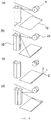
- control unit 40 may further include a second photosensor 42 having a function to determine the first start timing of the radiation of a modeling beam to the modeling plane 10 by detecting the modeling beam incident on a specific location of the modeling plane 10 and to synchronize the driving of the modeling beam source unit 15 and the driving of the second light guide unit 30.
- a third photosensor 43 having a function to determine the final end timing of the radiation of a modeling beam to the modeling plane 10 by detecting the modeling beam incident on a specific location of the modeling plane 10 may be further installed.
- the first start timing and final end timing of a modeling beam have a direct relation with the driving of an element that belongs to the first light guide unit 20 and the second light guide unit 30 and that is responsible for the stepping of each line scan.
- FIG. 8 shows one embodiment of the second photosensor 42 and the third photosensor 43 disposed in the '(1-1)-th configuration'. The first start timing and final end timing of a modeling beam radiated (scanned) to the modeling plane 10 are determined by the second photosensor 42 and the third photosensor 43.
- the second light guide unit 30 (the second polygon mirror 31) is an element responsible for the stepping of a line scan
- the second light guide unit 30 and the modeling beam source unit 15 are driven in conjunction with each other in response to the driving signal of the second light guide unit 30 and the driving signal of the modeling beam source unit 15, which are generated after the processing unit receives and processes the signals of the second photosensor 42 and the third photosensor 43.
- the head apparatus of the three-dimensional modeling equipment of the present invention may further include a modeling beam incident angle correction unit 50 having a function to enable a modeling beam to be vertically incident on the modeling plane 10 at all of points that form the modeling plane 10. As described above, this is to make output power density of a modeling beam uniform at each incident point.
- the modeling beam incident angle correction unit 50 according to one embodiment of FIG. 9 is a lens disposed over the modeling plane 10. The modeling beam incident angle correction unit 50 functions to induce a modeling beam, secondarily reflected by the second light guide unit 30, to be vertically incident on the modeling plane 10 after the modeling beam experiences twice refraction processes although the modeling beam has a different incident angle for each point.
- a modeling beam is incident on the first light guide unit 20 at a specific angle to the second axis 2.
- a scanning pattern may be a pattern formed as a plurality of line scans having the direction parallel to the second axis 2 is stepped at specific intervals in the direction of the first axis 1 (hereinafter referred to as a "first scanning pattern").
- FIGS. 3 and 6 show one embodiment of the first scanning pattern.
- a modeling beam is incident on the first light guide unit 20 at a specific angle to the second axis 2.
- a scanning pattern may be a pattern formed as a plurality of line scans having the direction parallel to the first axis 1 is stepped at specific intervals in the direction of the second axis 2 (hereinafter referred to as a "second scanning pattern").
- a second scanning pattern One embodiment of such a pattern is shown in FIGS. 4 and 5 .
- the modeling beams in the first scanning pattern and the second scanning pattern may be incident in parallel to the second axis 2, and may be incident in a direction in which the modeling beams are not included in a plane formed by the second axis 2 and the third axis 3.
- the incident direction of the modeling beam may be determined in relation to the location where the first light guide unit 20 and the second light guide unit 30 are installed.
- the first light guide unit 20 is configured to include a first polygon mirror 21.
- the first polygon mirror 21 is disposed using a fourth axis 4 parallel to the first axis 1 as its rotating central axis.
- the second light guide unit 30 is configured to include the second polygon mirror 31.
- the second polygon mirror 31 is disposed using a fifth axis 5 parallel to the third axis 3 as its rotating central axis.
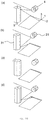
- a plurality of line scans in the direction parallel to the second axis 2 is performed when the first polygon mirror 21 is rotated, and the stepping of the plurality of line scans at a specific interval in the direction of the first axis 1 is performed when the second polygon mirror 31 is rotated.
- one line scan is performed by one side reflection surface of the first polygon mirror 21 in which the incident angle of a modeling beam continues to change while the first polygon mirror 21 is rotated.
- control of a modeling beam while it moves from one side reflection surface of the first polygon mirror 21 to another adjacent side reflection surface thereof may be performed by turning off the output of the modeling beam source unit, by blocking the modeling beam using an additional element, such as a shutter, or by applying a method using a shield film disposed near the modeling plane.
- a method for lowering the output of a modeling beam to the extent that the curing or sintering action of a modeling material is not generated although the modeling beam is incident on the modeling plane may be taken into consideration.
- FIG. 3 One embodiment of such a configuration is shown in FIG. 3 .
- first polygon mirror 21 is alternately rotated forward and backward, only one side reflection surface of the first polygon mirror 21 is used in all of the line scans.
- FIG. 10 One embodiment of such a configuration is shown in FIG. 10 . Such a configuration is not preferred. This is described later.
- the first light guide unit 20 is configured to include a seventh polygon mirror 24.
- the seventh polygon mirror 24 is disposed using a tenth axis 10x parallel to the third axis 3 as its rotating central axis.
- the second light guide unit 30 is configured to include an eighth polygon mirror 34.
- the eighth polygon mirror 34 is disposed using an eleventh axis 11x parallel to the first axis 1 as its rotating central axis. A plurality of line scans in the direction parallel to the second axis 2 is performed when the eighth polygon mirror 34 is rotated.
- the stepping of the plurality of line scans at a specific interval in the direction of the first axis 1 is performed when the seventh polygon mirror 24 is rotated.
- one line scan may be performed by one side reflection surface of the eighth polygon mirror 34 in which the incident angle of a modeling beam continues to change while the eighth polygon mirror 34 is rotated. Since the eighth polygon mirror 34 continues to rotate in one direction, control of a modeling beam while it moves from one side reflection surface of the eighth polygon mirror 34 to another adjacent side reflection surface thereof may be performed by turning off the output of the modeling beam source unit, by blocking the modeling beam using an additional element, such as a shutter, or by applying a method using a shield film disposed near the modeling plane.
- a method for lowering the output of a modeling beam to the extent that the curing or sintering action of a modeling material is not generated although the modeling beam is incident on the modeling plane may be taken into consideration. Furthermore, if the seventh polygon mirror 24 is alternately rotated forward and backward, only one side reflection surface of the seventh polygon mirror 24 is used in all of the line scans.
- the first light guide unit 20 is configured to include a third polygon mirror 22.
- the third polygon mirror 22 is disposed using a sixth axis 6 parallel to the first axis 1 as its rotating central axis.
- the second light guide unit 30 is configured to include a fourth polygon mirror 32.
- the fourth polygon mirror 32 is disposed using a seventh axis 7 parallel to the third axis 3 as its rotating central axis. A line scan in the direction parallel to the first axis 1 is performed when the fourth polygon mirror 32 is rotated. Stepping at a specific interval in the direction of the second axis 2 is performed when the third polygon mirror 22.
- One line scan is performed by one side reflection surface of the fourth polygon mirror 32 in which the incident angle of a modeling beam continues to change while the fourth polygon mirror 32 is rotated. If the fourth polygon mirror 32 continues to rotate in one direction, control of a modeling beam while it moves from one side reflection surface of the fourth polygon mirror 32 to another adjacent side reflection surface thereof may be performed by turning off the output of the modeling beam source unit, by blocking the modeling beam using an additional element, such as a shutter, or by applying a method using a shield film disposed near the modeling plane.
- a method for lowering the output of a modeling beam to the extent that the curing or sintering action of a modeling material is not generated although the modeling beam is incident on the modeling plane may be taken into consideration.
- each line scan in the direction of the second axis 2 is generated as the third polygon mirror 22 rotates at specific angular displacement and as a result, the location where a modeling beam is reflected in the side reflection surface of the fourth polygon mirror 32 is stepped. Furthermore, if the fourth polygon mirror 32 is alternately rotated forward and backward, only one side reflection surface of the fourth polygon mirror 32 is used in all of the line scans (In this case, such a configuration is not preferred. This is described later.)
- the first light guide unit 20 is configured to include a fifth polygon mirror 23.
- the fifth polygon mirror 23 is disposed using an eighth axis 8 that forms a specific angle to the third axis 3 as its rotating central axis.
- the second light guide unit 30 is configured to include a sixth polygon mirror 33.
- the sixth polygon mirror 33 is disposed using a ninth axis 9 parallel to the first axis 1 as its rotating central axis. A plurality of line scans in the direction parallel to the first axis 1 may be performed when the fifth polygon mirror 23 is rotated.
- Stepping at a specific interval in the direction of the second axis 2 is performed when the sixth polygon mirror 33 is rotated.
- One line scan is performed by one side reflection surface of the fifth polygon mirror 23 in which the incident angle of a modeling beam continues to change while the fifth polygon mirror 23 is rotated. If the fifth polygon mirror 23 continues to rotate in one direction, control of a modeling beam while it moves from one side reflection surface of the fifth polygon mirror 23 to another adjacent side reflection surface thereof may be performed by turning off the output of the modeling beam source unit, by blocking the modeling beam using an additional element, such as a shutter, or by applying a method using a shield film disposed near the modeling plane.
- a method for lowering the output of a modeling beam to the extent that the curing or sintering action of a modeling material is not generated although the modeling beam is incident on the modeling plane may be taken into consideration. Furthermore, the stepping of each line scan in the direction of the second axis 2 is generated as the sixth polygon mirror 33 rotates at specific angular displacement and thus the location where a modeling beam is reflected is stepped. Furthermore, if the fifth polygon mirror 23 is alternately rotated forward and backward, only one side reflection surface of the fifth polygon mirror 23 is used in all of the line scans.
- a method for scanning the modeling plane 10 using the head apparatus of the three-dimensional modeling equipment of the present invention is described below. To this end, it is a precondition that a modeling material is actually supplied to the aforementioned modeling plane 10 and located therein. When the scanning of a modeling beam for one modeling plane 10 is completed, one modeling layer is formed. Such modeling layers are stacked to form one three-dimensional model. In the scanning of the modeling plane 10, a portion to which a modeling beam has not been radiated should not be present. It is preferred that scanning is performed through an optimal path capable of minimizing a required scanning time.
- the first polygon mirror 21 is rotated in one direction, and the modeling beam source unit 15 starts to enable a modeling beam to be incident on the first polygon mirror 21.
- the modeling beam primarily reflected by the first polygon mirror 21 is secondarily reflected by the second polygon mirror 31, and performs a line scan on the modeling plane 10 in the direction parallel to the second axis 2.
- a modeling beam 11 is controlled so that it is not radiated to the modeling plane 10, so the line scan in the second step is terminated.
- control may be performed by turning off the output of the modeling beam source unit, by using an additional element, such as a shutter, or by using a shield film disposed near the modeling plane.
- a method for lowering the output of the modeling beam to the extent that the curing or sintering action of a modeling material is not generated although the modeling beam is incident on the modeling plane may be taken into consideration.
- the second polygon mirror 31 rotates at specific angular displacement and the first polygon mirror 21 continues to rotate in the same direction until a next reflection surface adjacent to a previous reflection surface reaches a specific location.
- the first step to the fourth step are repeatedly performed until the radiation of the modeling beam to the entire surface of the modeling plane 10 is completed.
- the first polygon mirror 21 may be configured to alternately rotate forward and backward as in a case shown in FIG. 10 .
- an actual profit using the present invention is reduced because the time taken for each line scan is increased due to the repetition of the forward rotation-stop-backward rotation-stop of the first polygon mirror 21.
- an electric motor element for driving the first polygon mirror 21 becomes complicated, and a good possibility that vibration and noise may be seriously generated in the repeated process must be taken into consideration. It is evident that the second polygon mirror 31 has to continue to rotate in one direction in the process of performing radiation on the one modeling plane 10.
- the second polygon mirror 31 when radiation to a next modeling plane 10 is performed after the one modeling plane 10 is illuminated, the second polygon mirror 31 may rotate in the same direction as the rotating direction in the radiation process for the previous modeling plane 10 or the second polygon mirror 31 may rotate in the direction opposite the rotating direction in the radiation process for the previous modeling plane 10.
- a problem such as that in the first polygon mirror 21 is not generated because the second polygon mirror 31 has to be in the stop state while a line scan is performed.
- the second polygon mirror 31 does not need to be essentially configured to have a mirror of a polygon form.
- FIG. 6 An embodiment of the procedure of the method is shown in FIG. 6 .
- the eighth polygon mirror 34 rotates in one direction and the modeling beam source unit 15 starts to enable a modeling beam to be incident on the seventh polygon mirror 24.
- the eighth polygon mirror 34 continues to rotate at a specific speed, the modeling beam primarily reflected by the seventh polygon mirror 24 is secondarily reflected by the eighth polygon mirror 34, and performs a line scan on the modeling plane 10 in the direction parallel to the second axis 2.
- the modeling beam 11 is controlled so that it is not radiated to the modeling plane 10, and thus the line scan in the second step is terminated.
- control may be performed by turning off the output of the modeling beam source unit, by using an additional element, such as a shutter, or by using a shield film disposed near the modeling plane.
- a method for lowering the output of the modeling beam to the extent that the curing or sintering action of a modeling material is not generated although the modeling beam is incident on the modeling plane may be taken into consideration.
- the seventh polygon mirror 24 rotates at specific angular displacement and the eighth polygon mirror 34 continues to rotate in the same direction until a next reflection surface adjacent to a previous reflection surface reaches a specific location.
- a total modeling time can be reduced.
- the first step to the fourth step are repeatedly performed until the radiation of the modeling beam to the entire surface of the modeling plane 10 is completed. In this method, it is preferred that the eighth polygon mirror 34 is rotated in one specific direction only.
- the eighth polygon mirror 34 is rotated in one direction only as described above, the time taken between one line scan and a next line scan can be minimized, and the time necessary for the eighth polygon mirror 34 to be accelerated from a stop state can also be minimized. Accordingly, an overall modeling time can be reduced.
- the eighth polygon mirror 34 may be configured to alternately rotate forward and backward. In such a configuration, an actual profit using the present invention is reduced because the time taken for each line scan is increased due to the repetition of the forward rotation-stop-backward rotation-stop of the eighth polygon mirror 34. Furthermore, an electric motor element for driving the eighth polygon mirror 34 becomes complicated, and a good possibility that vibration and noise may be seriously generated in the repeated process must be taken into consideration.
- the seventh polygon mirror 24 has to continue to rotate in one direction in the process of performing radiation on the one modeling plane 10.
- the seventh polygon mirror 24 may rotate in the same direction as the rotating direction in the radiation process for the previous modeling plane 10 or the seventh polygon mirror 24 may rotate in the direction opposite the rotating direction in the radiation process for the previous modeling plane 10.
- a problem, such as that in the eighth polygon mirror 34 is not generated because the seventh polygon mirror 24 has to be in the stop state while a line scan is performed.
- the seventh polygon mirror 24 does not need to be essentially configured to have a mirror of a polygon form.
- the fourth polygon mirror 32 rotates in one direction, and the modeling beam source unit 15 starts to enable a modeling beam to be incident on the third polygon mirror 22.
- the modeling beam primarily reflected by the third polygon mirror 22 is secondarily reflected by the fourth polygon mirror 32, and performs a line scan on the modeling plane 10 in the direction parallel to the first axis 1.
- the modeling beam 11 is controlled so that it is not radiated to the modeling plane 10, and the line scan in the second step is terminated.
- control may be performed by turning off the output of the modeling beam source unit, by using an additional element, such as a shutter, or by using a shield film disposed near the modeling plane.
- a method for lowering the output of the modeling beam to the extent that the curing or sintering action of a modeling material is not generated although the modeling beam is incident on the modeling plane may be taken into consideration.
- the third polygon mirror 22 rotates at specific angular displacement and the fourth polygon mirror 32 continues to rotate in the same direction until a next reflection surface adjacent to a previous reflection surface reaches a specific location.
- the first step to the fourth step are repeatedly performed until the radiation of the modeling beam to the entire surface of the modeling plane 10 is completed.
- the fourth polygon mirror 32 is rotated in one specific direction only.
- the third polygon mirror 22 has to continue to rotate in the same direction in the process of radiating the modeling beam to the one modeling plane 10.
- the third polygon mirror 22 may start to rotate in the same direction as the rotating direction in the radiation for the previous modeling plane 10 or may start to rotate in the direction opposite the rotating direction in the radiation for the previous modeling plane 10. In the latter case, the third polygon mirror 22 does not need to be essentially configured to have a mirror of a polygon form.
- the fifth polygon mirror 23 rotates in one direction, and the modeling beam source unit 15 starts to enable a modeling beam to be incident on the fifth polygon mirror 23.
- the modeling beam primarily reflected by the fifth polygon mirror 23 is secondarily reflected by the sixth polygon mirror 33, and performs a line scan on the modeling plane 10 in the direction parallel to the first axis 1.
- the modeling beam 11 is controlled so that it is not radiated to the modeling plane 10, and thus the line scan in the second step is terminated.
- control may be performed by turning off the output of the modeling beam source unit, by using an additional element, such as a shutter, or by using a shield film disposed near the modeling plane.
- a method for lowering the output of the modeling beam to the extent that the curing or sintering action of a modeling material is not generated although the modeling beam is incident on the modeling plane may be taken into consideration.
- the sixth polygon mirror 33 rotates at specific angular displacement and the fifth polygon mirror 23 continues to rotate in the same direction until a next reflection surface adjacent to a previous reflection surface reaches a specific location.
- the first step to the fourth step are repeatedly performed until the radiation of the modeling beam to the entire surface of the modeling plane 10 is completed.
- the fifth polygon mirror 23 is rotated in one specific direction only.
- the sixth polygon mirror 33 has to continue to rotate in the same direction in the process of radiating the modeling beam to the one modeling plane 10.
- the sixth polygon mirror 33 may start to rotate in the same direction as the rotating direction in the radiation for the previous modeling plane 10 or may start to rotate in the direction opposite the rotating direction in the radiation for the previous modeling plane 10. In the latter case, the sixth polygon mirror 33 does not need to be essentially configured to have a mirror of a polygon form
Abstract
Description
- This application claims priority to and the benefit of Korean Patent Application No.
10-2014-0139616, filed on October 16, 2014 - The present invention relates to the head apparatus of the three-dimensional modeling equipment and a method for scanning a modeling plane using the same and, more particularly, to the head apparatus of the three-dimensional modeling equipment which has a configuration including polygon mirrors that rotate in one direction, can perform 2-axis scanning at high speed by a combination of the polygon mirrors, can easily control timing and a location to which a modeling beam is radiated, and has an advantage of improving modeling precision, and a method for scanning a modeling plane using the same.
- 3D printing is one of methods for fabricating a product, and has been chiefly used to fabricate a prototype because it has a smaller loss of materials than conventional cutting processing due to the use of a stacking method and it consumes a relatively low production cost. Recently, the possibility of the technology of this field as a next-generation production technology has been recognized in addition to the fabrication of a prototype. The reason for this is that the fabrication speed has been increased, the completeness (resolution) of an output matter has been enhanced, available materials have been diversified, and the availability of individuals has been improved to the small size of an apparatus. Such a 3D printing method includes methods, such as a stereo lithography apparatus (SLA), selective laser sintering (SLS), and fused deposition modeling (SDM).
- Korean Patent Application Publication No.
1996-0024766 prior art 1") discloses a 3D model forming apparatus, including a controller which corrects a control pulse based on a signal fed back by a motor so that the motor is rotated at a target speed, a motor driver which supplies a driving voltage to the motor0-∥ in response to the control pulse output by the controller, a laser oscillation unit which generates a laser beam, and an attenuator which attenuates a laser beam output to the scan lens side in response to the driving voltage, in order to solve a problem in that a model is deformed into an unwanted structure because the radiation time of a laser beam becomes longer than a steady movement section in an acceleration and deceleration section that appears near the driving start point and driving end point of a servo motor with respect to a beam modeling apparatus of an X-Y plotter method. - The
prior art 1, such as that shown inFIG. 1 , has a first problem in that control precision is deteriorated compared to a method of controlling a beam path because a head directly moves to a beam radiation point through a 2-axis moving rail and radiates a modeling beam, a second problem in that modeling quality is deteriorated because the relatively heavy head is directly moved and vibration is generated due to the acceleration or deceleration of the head, and a third problem in that such a vibration problem becomes further severe when a modeling speed is increased. - In the present invention, in order to implement the radiation of a modeling beam not having an omitted portion with respect to a one modeling plane, the head does not directly move to a modeling portion and does not radiate a modeling beam. Instead, two sets of optical elements called polygon mirrors are properly arranged in the space, and the angular displacement and angular speed of two polygon mirrors and a modeling beam source unit for generating a modeling beam are controlled so that they operate in conjunction with each other. Furthermore, since the polygon mirrors are rotated in one direction, a vibration possibility generated due to the stop or acceleration of the polygon mirror and a change in the rotating direction of the polygon mirror can be minimized, and a modeling speed can be increased. Furthermore, the modeling beam source unit is controlled or a separate element is introduced in order to correct a difference in the modeling beam output power density in each incident point of a modeling plane and a difference in the path length of a modeling beam.
- The present invention has a first advantage in that the radiation of a modeling beam can be performed at high speed because the polygon mirrors rotating in a single direction are adopted and the polygon mirror continues to rotate without a stop, a second advantage in that vibration and noise generated by the head apparatus can be reduced and thus quality of a modeling layer formed in a
modeling plane 10 can be improved because control is performed through control of the rotating angular speed and rotating angular displacement of the two polygon mirrors in controlling the radiation location of a modeling beam, and a third advantage in that modeling quality can be improved by controlling the output value of a modeling beam through a controller or implementing uniform modeling beam output power density with respect to theentire modeling plane 10 by applying a modeling beam incidentangle correction unit 50. Furthermore, the present invention may be applied to three-dimensional modeling apparatuses of various methods including the SLA or SLS method. -
-
FIG. 1 is a perspective view showing the configuration of a conventional technology. -
FIG. 2 is an explanatory diagram showing the configuration of one embodiment of the head apparatus of the three-dimensional modeling equipment according to the present invention. -
FIG. 3 is a perspective view showing one embodiment (a (1-1)-th configuration) of a method for scanning a modeling plane using the head apparatus of the three-dimensional modeling equipment according to the present invention. -
FIG. 4 is a perspective view showing one embodiment (a (2-1)-th configuration) of a method for scanning a modeling plane using the head apparatus of the three-dimensional modeling equipment according to the present invention. -
FIG. 5 is a perspective view showing one embodiment (a (2-2)-th configuration) of a method for scanning a modeling plane using the head apparatus of the three-dimensional modeling equipment according to the present invention. -
FIG. 6 is a perspective view showing one embodiment (a (1-2)-th configuration) of a method for scanning a modeling plane using the head apparatus of the three-dimensional modeling equipment according to the present invention. -
FIG. 7 is a perspective view showing one embodiment the head apparatus andfirst photosensor 41 of three-dimensional modeling equipment according to the present invention. -
FIG. 8 is a perspective view showing one embodiment of the head apparatus,second photosensor 42, andthird photosensor 43 of three-dimensional modeling equipment according to the present invention. -
FIG. 9 is a cross-sectional view showing one embodiment of a modeling beam incidentangle correction unit 50 of the present invention. -
FIG. 10 is an explanatory diagram showing a procedure when afirst polygon mirror 21 is rotated forward and backward in the one embodiment (the (1-1)-th configuration) of the method for scanning themodeling plane 10 using the head apparatus of the three-dimensional modeling equipment according to the present invention. - The head apparatus of three-dimensional modeling equipment according to the present invention may include, in order to implement a function to radiate a modeling beam to the entire surface of a
modeling plane 10 perpendicular to athird axis 3 and including afirst axis 1 and asecond axis 2 in a specific scanning pattern, thefirst axis 1 and thesecond axis 2 being perpendicular to each other, a modelingbeam source unit 15 which generates the modeling beam, a firstlight guide unit 20 disposed at a specific location over themodeling plane 10 and having a function to primarily reflect the modeling beam from the modelingbeam source unit 15 and to enable the primarily reflected modeling beam to be incident on a secondlight guide unit 30, the secondlight guide unit 30 disposed at a specific location over themodeling plane 10 and having a function to secondarily reflect the modeling beam incident from the firstlight guide unit 20 and to enable the secondarily reflected modeling beam to be incident on themodeling plane 10, and acontrol unit 40 which turns on or off the modeling beam, adjusts output power of the modeling beam, and controls the firstlight guide unit 20 and the secondlight guide unit 30 together. At least one of the firstlight guide unit 20 and the secondlight guide unit 30 may include a polygon mirror having a specific number of light reflection surfaces on the side thereof and rotating in one direction around a specific rotating axis . - Furthermore, the head apparatus of the three-dimensional modeling equipment of the present invention may further include a modeling beam incident
angle correction unit 50 having a function to enable the modeling beam to be vertically incident on themodeling plane 10 in all of points forming themodeling plane 10. - In the head apparatus of the three-dimensional modeling equipment of the present invention, the
control unit 40 may control the pulse amplitude or pulse frequency of the modeling beam in order to correct a difference in the path length which is necessary for the modeling beam to reach each of points forming themodeling plane 10 or a difference in output power density of a modeling beam in each of the points which is caused depending on a difference in the incident angle of the modeling beam. - In the head apparatus of the three-dimensional modeling equipment of the present invention, the
control unit 40 may include afirst photosensor 41 having a function to determine the start timing of each of a plurality of line scans in a direction parallel to thesecond axis 2 by sensing a modeling beam incident on a specific point and to synchronize the driving of the modelingbeam source unit 15 and the driving of the firstlight guide unit 20 or the secondlight guide unit 30. - In the head apparatus of the three-dimensional modeling equipment of the present invention, the
control unit 40 may further include afourth photosensor 44 having a function to determine end timing of each of a plurality of line scans in the direction parallel to thesecond axis 2 by sensing a modeling beam incident on a specific point and to synchronize the driving of the modelingbeam source unit 15 and the driving of the firstlight guide unit 20 or the secondlight guide unit 30. - In the head apparatus of the three-dimensional modeling equipment of the present invention, the
control unit 40 may include asecond photosensor 42 having a function to determine first start timing of the radiation of a modeling beam to themodeling plane 10 by sensing the modeling beam incident on a specific location of themodeling plane 10 and to synchronize the driving of the modelingbeam source unit 15 and the driving of the firstlight guide unit 20 or the secondlight guide unit 30. - In the head apparatus of the three-dimensional modeling equipment of the present invention, the
control unit 40 may further include athird photosensor 43 having a function to determine the final end timing of the radiation of a modeling beam to themodeling plane 10 by sending the modeling beam incident on a specific location of themodeling plane 10. - In the head apparatus of the three-dimensional modeling equipment of the present invention, the modeling beam may be incident on the first
light guide unit 20 while forming a specific angle to thesecond axis 2. The scanning pattern may be a pattern formed as a plurality of line scans having a direction parallel to thesecond axis 2 is stepped at a specific interval in the direction of thefirst axis 1. - The first
light guide unit 20 of the head apparatus of the three-dimensional modeling equipment of the present invention may include afirst polygon mirror 21. Thefirst polygon mirror 21 may be disposed using afourth axis 4 parallel to thefirst axis 1 as its rotating central axis. The secondlight guide unit 30 may include asecond polygon mirror 31. Thesecond polygon mirror 31 may be disposed using afifth axis 5 parallel to thethird axis 3 as its rotating central axis. The plurality of line scans in the direction parallel to thesecond axis 2 may be performed as thefirst polygon mirror 21 is rotated. The stepping at the specific interval in the direction of thefirst axis 1 may be performed as thesecond polygon mirror 31 is rotated. - A method for scanning the
modeling plane 10 according to the present invention includes the steps of, first, rotating, by thefirst polygon mirror 21, in one direction and starting, by the modelingbeam source unit 15, to have a modeling beam incident on thefirst polygon mirror 21; second, enabling a modeling beam primarily reflected by thefirst polygon mirror 21 to be secondarily reflected by thesecond polygon mirror 31 and then to perform a line scan on themodeling plane 10 in the direction parallel to thesecond axis 2 while thefirst polygon mirror 21 continues to rotate at a specific speed; third, controlling themodeling beam 11 so that themodeling beam 11 is not radiated to themodeling plane 10, thereby terminating the line scan in the step (ii); fourth, rotating, by thesecond polygon mirror 31, at specific angular displacement and continuing to rotate, by thefirst polygon mirror 21, in the same rotating direction until a next reflection surface adjacent to a previous reflection surface reaches a specific location in order to perform a next line scan after stepping at a specific interval in the direction of thefirst axis 1 after the line scan in the second step; and fifth, repeatedly performing the step (i) to the step (iv) until the radiation of the modeling beam to the entire surface of themodeling plane 10 is completed. Thefirst polygon mirror 21 may be rotated only in a single direction. - The method for scanning the
modeling plane 10 according to the present invention may further include the step of preparing, by thesecond polygon mirror 31, rotation in the direction identical with the rotating direction in the fifth step after the fifth step. - The method for scanning the
modeling plane 10 according to the present invention may further include the step of preparing, by thesecond polygon mirror 31, rotation in the direction opposite the rotating direction in the fifth step after the fifth step. - In the method for scanning the
modeling plane 10 according to the present invention, the rotation of thesecond polygon mirror 31 and the rotation of thefirst polygon mirror 21 in the fourth step may be simultaneously performed. - In the head apparatus of the three-dimensional modeling equipment of the present invention, the modeling beam may be incident on the first
light guide unit 20 while forming a specific angle to thesecond axis 2. The scanning pattern may be a pattern formed as a plurality of line scans having a direction parallel to thefirst axis 1 is stepped at a specific interval in the direction of thesecond axis 2. - In the head apparatus of the three-dimensional modeling equipment of the present invention, the first
light guide unit 20 may include athird polygon mirror 22. Thethird polygon mirror 22 may be disposed using asixth axis 6 parallel to thefirst axis 1 as its rotating central axis. The secondlight guide unit 30 may include afourth polygon mirror 32. Thefourth polygon mirror 32 may be disposed using a seventh axis 7 parallel to thethird axis 3 as its rotating central axis. The line scan in the direction parallel to thefirst axis 1 may be performed as thefourth polygon mirror 32 is rotated. The stepping at the specific interval in the direction of thesecond axis 2 may be performed as thethird polygon mirror 22 is rotated. - A method for scanning the
modeling plane 10 according to the present invention includes the steps of, first, rotating, by thefourth polygon mirror 32, in one direction and starting, by the modelingbeam source unit 15, to have a modeling beam incident on thethird polygon mirror 22; second, enabling a modeling beam primarily reflected by thethird polygon mirror 22 to be secondarily reflected by thefourth polygon mirror 32 and then to perform a line scan on themodeling plane 10 in the direction parallel to thefirst axis 1 while thefourth polygon mirror 32 continues to rotate at a specific speed; third, controlling themodeling beam 11 so that themodeling beam 11 is not radiated to themodeling plane 10, thereby terminating the line scan in the step (ii); fourth, rotating, by thethird polygon mirror 22, at specific angular displacement and continuing to rotate, by thefourth polygon mirror 32, in the same rotating direction until a next reflection surface adjacent to a previous reflection surface reaches a specific location in order to perform a next line scan after stepping at a specific interval in the direction of thesecond axis 2 after the line scan in the second step; and fifth, repeatedly performing the first step to the fourth step until the radiation of the modeling beam to the entire surface of themodeling plane 10 is completed. Thefourth polygon mirror 32 may be rotated in one specific direction only. - The method for scanning a modeling plane according to the present invention may further include the step of preparing, by the
third polygon mirror 22, rotating in the direction identical with the rotating direction in the fifth step after the fifth step. - The method for scanning a modeling plane according to the present invention may further include the step of preparing, by the
third polygon mirror 22, rotation in the direction opposite the rotating direction in the fifth step after the fifth step. - In the method for scanning a modeling plane according to the present invention, the rotation of the
third polygon mirror 22 and the rotation of thefourth polygon mirror 32 in the fourth step may be simultaneously performed. - In the head apparatus of the three-dimensional modeling equipment of the present invention, the first
light guide unit 20 may include afifth polygon mirror 23. Thefifth polygon mirror 23 may be disposed using an eighth axis 8 having a specific angle to thethird axis 3 as its rotating central axis. The secondlight guide unit 30 may include asixth polygon mirror 33. Thesixth polygon mirror 33 may be disposed using a ninth axis 9 parallel to thefirst axis 1 as its rotating central axis. A plurality of line scans in the direction parallel to thefirst axis 1 may be performed as thefifth polygon mirror 23 is rotated. The stepping at the specific interval in the direction of thesecond axis 2 may be performed as thesixth polygon mirror 33 is rotated. - A method for scanning the modeling plane 10 according to the present invention includes the steps of, first, rotating, by the fifth polygon mirror 23, in one direction and starting, by the modeling beam source unit 15, to have a modeling beam incident on the fifth polygon mirror 23; second, enabling a modeling beam primarily reflected by the fifth polygon mirror 23 to be secondarily reflected by the sixth polygon mirror 33 and then to perform a line scan on the modeling plane 10 in the direction parallel to the first axis 1 while the fifth polygon mirror 23 continues to rotate at a specific speed; third, controlling the modeling beam 11 so that the modeling beam 11 may be not radiated to the modeling plane 10, thereby terminating the line scan in the step (ii); fourth, rotating, by the sixth polygon mirror 33, at specific angular displacement and continuing to rotate, by the fifth polygon mirror 23, in the same rotating direction until a next reflection surface adjacent to a previous reflection surface reaches a specific location in order to perform a next line scan after stepping at a specific interval in the direction of the second axis 2 after the line scan in the second step; and fifth, repeatedly performing the step (i) to the (iv) step until the radiation of the modeling beam to the entire surface of the modeling plane 10 is completed. The
fifth polygon mirror 23 may be rotated in one specific direction only. - The method for scanning the
modeling plane 10 according to the present invention may further include the step of preparing, by thesixth polygon mirror 33, rotation in the direction identical with the rotating direction in the fifth step after the fifth step. - The method for scanning the
modeling plane 10 according to the present invention may further include the step of preparing, by thesixth polygon mirror 33, rotation in the direction opposite the rotating direction in the fifth step after the fifth step. - In the method for scanning the
modeling plane 10 according to the present invention, the rotation of thefifth polygon mirror 23 and the rotation of thesixth polygon mirror 33 in the fourth step may be simultaneously performed. - In the head apparatus of the three-dimensional modeling equipment of the present invention, the first
light guide unit 20 may include aseventh polygon mirror 24. Theseventh polygon mirror 24 may be disposed using atenth axis 10x parallel to thethird axis 3 as its rotating central axis. The secondlight guide unit 30 may include aneighth polygon mirror 34. Theeighth polygon mirror 34 may be disposed using aneleventh axis 11x parallel to thefirst axis 1 as its rotating central axis. A plurality of line scans in the direction parallel to thesecond axis 2 may be performed as theeighth polygon mirror 34 is rotated. The stepping at the specific interval in the direction of thefirst axis 1 may be performed as theseventh polygon mirror 24 is rotated. - A method for scanning a modeling plane according to the present invention includes the steps of, first, rotating, by the eighth polygon mirror 34, in one direction and starting, by the modeling beam source unit 15, to have a modeling beam incident on the seventh polygon mirror 24; second, enabling a modeling beam primarily reflected by the seventh polygon mirror 24 to be secondarily reflected by the eighth polygon mirror 34 and then to perform a line scan on the modeling plane 10 in the direction parallel to the second axis 2 while the eighth polygon mirror 34 continues to rotate at a specific speed; third, controlling the modeling beam 11 so that the modeling beam 11 is not radiated to the modeling plane 10, thereby terminating the line scan in the second step; fourth, rotating, by the seventh polygon mirror 24, at specific angular displacement and continuing to rotate, by the eighth polygon mirror 34, in the same rotating direction until a next reflection surface adjacent to a previous reflection surface reaches a specific location in order to perform a next line scan after stepping at a specific interval in the direction of the first axis 1 after the line scan in the second step; and fifth, repeatedly performing the first step to the fourth step until the radiation of the modeling beam to the entire surface of the modeling plane 10 is completed. The
eighth polygon mirror 34 may be rotated in one specific direction only. - The method for scanning a modeling plane according to the present invention may further include the step of preparing, by the
seventh polygon mirror 24, rotation in the direction identical with the rotating direction in the fifth step after the fifth step. - The method for scanning a modeling plane according to the present invention may further include the step of preparing, by the
seventh polygon mirror 24, rotation in the direction opposite the rotating direction in the fifth step after the fifth step. - In the method for scanning a modeling plane according to the present invention, the rotation of the
seventh polygon mirror 24 and the rotation of theeighth polygon mirror 34 in the fourth step may be simultaneously performed. - Furthermore, a three-dimensional modeling apparatus of the present invention may include the aforementioned head apparatus.
- The head apparatus of three-dimensional modeling equipment according to the present invention includes a modeling
beam source unit 15 which generates a modeling beam, a firstlight guide unit 20 which has a modeling beam incident on a secondlight guide unit 30 by primarily reflecting the modeling beam, the secondlight guide unit 30 which functions to have a modeling beam received from the firstlight guide unit 20 incident on amodeling plane 10 by secondarily reflecting the received modeling beam, and acontrol unit 40 which turns on or off the modeling beam, adjusts output power of the modeling beam, and controls the firstlight guide unit 20 and the secondlight guide unit 30 together, so that they operate in conjunction with each other as major elements. The head apparatus functions to radiate a modeling beam to theentire modeling plane 10 in a specific scanning pattern. A schematic diagram of such a configuration is shown inFIG. 2 . - Related terms are defined below prior to a description of the present invention in such a way as to describe the major elements and embodiments.
- The
modeling plane 10 also means a region in which a modeling beam whose path is controlled is radiated in the head apparatus of the three-dimensional modeling equipment according to the present invention, and also means a logical region which includes afirst axis 1 and asecond axis 2 that are perpendicular to each other and in which a location on the plane of the region is described as coordinate values according to thefirst axis 1 and thesecond axis 2 in order to mathematically represent the region in which a modeling beam is actually radiated. Anactual modeling plane 10 may be directly exposed to the outside or may have a state shielded by a transparent member through which a modeling beam can pass although the modeling beam is not directly radiated to the modeling plane. Furthermore, themodeling plane 10 may also be represented as an effective forming region in that energy is applied to a modeling beam and the generation of an action, such as photo curing or sintering curing, is limited to the region of themodeling plane 10. - The
first axis 1, thesecond axis 2 or athird axis 3 is a criterion in describing a relation between the scanning direction and pattern of a modeling beam or the location of a polygon mirror rotating axis with respect to themodeling plane 10 to be described later. Thethird axis 3 is an axis perpendicular to both thefirst axis 1 and thesecond axis 2. Thefirst axis 1 and thesecond axis 2 are randomly located on anactual modeling plane 10. - The modeling
beam source unit 15 functions to generate a modeling beam and to enable the modeling beam to be incident on the firstlight guide unit 20 to be described later. The modeling beam is not limited to the type of light, such as ultraviolet rays (UV rays) or a laser, because it has only to have energy necessary to cure a modeling material used. In this case, a laser is suitable for use as a modeling beam because high energy can be condensed and output intensity and on/off control of the laser can be easily controlled if the laser is used. The output and wavelength of a laser needs to be determined in accordance with a modeling material used. In order to generate a laser, a device, such as a laser diode (LD) or a VCSEL, may be used, but is not limited thereto. A single device does not need to be used because a beam of a single channel is used as a modeling beam. A laser array may be formed using a plurality of devices, and beams from the laser array may be condensed as a single laser beam using a relay module. Furthermore, the improvement of quality of a modeling beam or the design of a configuration for reducing the size of the head apparatus by applying various optical elements, such as an optical modulation module, a condensing lens, and a prism, may also be taken into consideration. - The first
light guide unit 20 and the secondlight guide unit 30 are located in the space over themodeling plane 10 so that they are not parallel to each other. The firstlight guide unit 20 and the secondlight guide unit 30 continuously determine the location where a modeling beam is radiated with respect to time so that an omitted portion is not generated in scanning for themodeling plane 10. From a viewpoint of a modeling beam, a modeling beam from the modelingbeam source unit 15 is primarily reflected by the firstlight guide unit 20 and incident on the secondlight guide unit 30, and is then secondarily reflected by the secondlight guide unit 30 and incident on themodeling plane 10. The present invention proposes that one or more of the firstlight guide unit 20 and the secondlight guide unit 30 has a specific number of light reflection surfaces on its side and includes a polygon mirror that rotates in one direction around a specific rotating axis. A cross-sectional shape of the polygon mirror, which is perpendicular to a rotating axis, needs to be a polygon, and a lateral surface of the polygon mirror needs to be configured to reflect a modeling beam. More preferably, if a polygon mirror whose cross-sectional shape is a regular polygon is adopted, it is advantageous because the rotating speed and rotating direction of the polygon mirror can be precisely controlled. The cross section of the polygon mirror may be a regular quadrilateral, a regular pentagon, a regular hexagon or a regular octagon, but is not limited thereto. As will be described later, there is an advantage in that the length of a (e.g., regular quadrilateral) line scan can be increased as the parameter of a regular polygon in the cross section of a polygon mirror is reduced because once line scan is performed by one side reflection surface of the polygon mirror. However, there is a disadvantage in that the rotating speed of the polygon mirror needs to be increased in order to produce the same modeling speed because the rotating angular displacement of the polygon mirror needs to be increased in order to perform one line scan. Accordingly, it is necessary to trade off the advantage and the disadvantage by selecting a polygon mirror having a proper shape depending on the size of themodeling plane 10. Furthermore, the side reflection surface may be a rectangle or trapezoid having the same shape and size. In this case, a general shape of the polygon mirror may be a regular polygon post or a regular polygon horn post. The polygon mirror may be configured to have a shape having any one of a regular polygon post and a regular polygon horn post depending on an angle at which the rotating axis of the polygon mirror has been installed, the incident angle of a modeling beam, a location between the firstlight guide unit 20 and the secondlight guide unit 30, or the size of the head apparatus of the present invention. In embodiments ofFIGS. 2 to 8 , the firstlight guide unit 20 has been implemented to have a shape of a regular octagon post and the secondlight guide unit 30 has been implemented to have a shape of a regular hexagon post. - The rotating axis of the polygon mirror may be disposed at a specific location over the
modeling plane 10 in various manners. Furthermore, reflection surface processing needs to be performed on the top and bottom surfaces of the polygon mirror in addition to the side of the polygon mirror. This is described later because it is related to afirst photosensor 41. Furthermore, such a polygon mirror may be applied to both the firstlight guide unit 20 and the secondlight guide unit 30, but may be applied to only one of the firstlight guide unit 20 and the secondlight guide unit 30. - The first
light guide unit 20 first receives a modeling beam. In general, the incident direction of the modeling beam incident from the modelingbeam source unit 15 has been fixed. Accordingly, the length of the firstlight guide unit 20 in its rotating axis direction may be relatively short. In contrast, the secondlight guide unit 30 is configured to secondarily reflect a modeling beam primarily reflected by the firstlight guide unit 20. The length of the secondlight guide unit 30 in its rotating axis direction needs to be set to be relatively long. - The
control unit 40 associates and controls the modelingbeam source unit 15, the firstlight guide unit 20 and the secondlight guide unit 30. A detailed target to be controlled by thecontrol unit 40 may turn on or off the modeling beam, adjust output power of the modeling beam, and control the firstlight guide unit 20 and the secondlight guide unit 30 together. A radiation location may be specified with respect to themodeling plane 10 of a modeling beam depending on control of the rotating angle of the firstlight guide unit 20 and the secondlight guide unit 30. A modeling layer may be formed at the specified radiation location by controlling the on/off of the modeling beam based on information about an image of the modeling layer. Thecontrol unit 40 basically includes a processing unit for generating a proper control signal with respect to a control parameter and a driving unit for driving a corresponding element by processing the control signal generated by the processing unit. The processing unit may be implemented using hardware, such as a circuit, or may be configured in software, such as a program. Control of the on/off of a modeling beam may be performed by controlling the on/off of a modeling beam generation device -LD or VCSEL or may be implemented through control of additional elements, such as a shutter for selectively transmitting or blocking a modeling beam generated by the modeling beam generation device over time, but the present invention is not limited thereto. More specifically, control of the output value of a modeling beam includes controlling the amplitude or frequency of a pulse which forms a modeling beam. This is required to correct a difference between beam path lengths that are necessary for a modeling beam to reach each of points that form themodeling plane 10 or a difference in the output power density of a modeling beam at each point which is caused depending on a difference between the incident angles of modeling beams. This is described in detail below. When a modeling beam is vertically incident on themodeling plane 10, the incident area of the modeling beam is a minimum, and thus output power density of the modeling beam is increased. In contrast, when a modeling beam is incident on themodeling plane 10 at an oblique angle, the incident area of the modeling beam is increased, and thus output power density of the modeling beam is reduced. However, the degree of an action, such as the curing-photo curing or powder sintering of a modeling beam for a modeling material, is proportional to the size of modeling beam output power density. Accordingly, in order to secure quality of a modeling layer by guaranteeing uniform modeling beam output power density with respect to the entire area of themodeling plane 10, it is necessary to control the output value of the modeling beam as described above. Furthermore, in particular, if the size of the head apparatus of the present invention is increased, there will be a difference in the energy loss degree of a modeling beam depending on a beam path length that is necessary for the modeling beam to reach each of points forming themodeling plane 10. Accordingly, it is necessary to correct the difference. - Control of the first
light guide unit 20 and the secondlight guide unit 30 by thecontrol unit 40 is performed by controlling the rotation of the polygon mirror. Major control parameters include the rotating angular speed, rotating angular displacement and rotating angular acceleration of the polygon mirror. Such control parameters need to follow the control signal of thecontrol unit 40 with a small error within a small lead time. To this end, an electromotive control method may be preferably used. More preferably, an electric servo-motor capable of implementing the rotating angular speed, rotating angular displacement, and rotating angular acceleration in response to a control signal (electrical signal) that varies over time may be used, but the present invention is not limited thereto. - Furthermore, the
control unit 40 may further include thefirst photosensor 41 having a function to determine the start timing of each of a plurality of line scans in the direction parallel to thefirst axis 1 or thesecond axis 2 by detecting a modeling beam incident on a specific point and to synchronize the driving of the modelingbeam source unit 15 and the driving of the firstlight guide unit 20 or the secondlight guide unit 30, in controlling the driving of the polygon mirrors that form the firstlight guide unit 20 and the secondlight guide unit 30. One embodiment of thefirst photosensor 41 which may be applied to a '(1-1)-th configuration' to be described later is shown inFIG. 7 . In the '(1-1)-th configuration', thefirst polygon mirror 21 performs a line scan while rotating in a single direction. A point at which a modeling beam reflected by thefirst polygon mirror 21 is incident on the side (reflection surface) of thesecond polygon mirror 31 is formed from top to bottom. A method for reflecting a modeling beam toward the top surface of thesecond polygon mirror 31 right before a next line scan is started after one line scan is terminated and disposing thefirst photosensor 41 in a corresponding path is taken into consideration (FIG. 7(a) ). In the above embodiment, since the firstlight guide unit 20 is an element responsible for a line scan, the subject of synchronization control by thefirst photosensor 41 is the firstlight guide unit 20 and the modelingbeam source unit 15. In a configuration (e.g., a (2-1)-th configuration) in which the secondlight guide unit 30 is an element responsible for a line scan, the subject of synchronization control by thefirst photosensor 41 may be the secondlight guide unit 30 and the modelingbeam source unit 15. -
FIG. 7(b) shows one embodiment in which tempering processing has been performed on the edge of the second light guide unit 30 (the second polygon mirror 31) so that the edge has an inclined plane having a specific tilt angle and a modeling beam reflected by the inclined plane is detected. In this case, in the (1-1)-th configuration, thesecond polygon mirror 31 is subjected to angular displacement of a specific angle. In order to continue to detect a modeling beam reflected by the tempered inclined plane for each line scan, thefirst photosensor 41 may be arranged in the form of a plurality of arrays as shown inFIG. 7(b) . The output signal of thefirst photosensor 41 is transferred to the processing unit. The processing unit may determine the start timing of the line scan using the output signal, and may synchronize the modelingbeam source unit 15 and the first light guide unit 20 (the first polygon mirror 21) using the start timing. Thecontrol unit 40 may perform control by precisely controlling only the angular displacement of the first light guide unit 20 (the first polygon mirror 21). However, when a process error and response delay inherent in a mechanical element, such as a servo motor, is taken into consideration, an effect of correcting such an error, etc. can be obtained through an additional element, such as thefirst photosensor 41. In conclusion, the first light guide unit 20 (the first polygon mirror 21) and the modelingbeam source unit 15 may operate in conjunction with each other in response to the driving signal of the firstlight guide unit 20 and the driving signal of the modelingbeam source unit 15, which are generated after thecontrol unit 40 processes a signal generated by thefirst photosensor 41. Furthermore, thecontrol unit 40 may further include afourth photosensor 44 having a function to determine the end timing of each of a plurality of line scans in the direction parallel to thefirst axis 1 or thesecond axis 2 by detecting a modeling beam incident on a specific point and to synchronize the driving of the modelingbeam source unit 15 and the driving of the firstlight guide unit 20 or the secondlight guide unit 30. For example,FIG. 7(c) shows one embodiment of a configuration in which thefourth photosensor 44 is selectively further disposed under the second light guide unit 30 (the second polygon mirror 31) to determine the end timing of each line scan. - Furthermore, the
control unit 40 may further include asecond photosensor 42 having a function to determine the first start timing of the radiation of a modeling beam to themodeling plane 10 by detecting the modeling beam incident on a specific location of themodeling plane 10 and to synchronize the driving of the modelingbeam source unit 15 and the driving of the secondlight guide unit 30. Furthermore, athird photosensor 43 having a function to determine the final end timing of the radiation of a modeling beam to themodeling plane 10 by detecting the modeling beam incident on a specific location of themodeling plane 10 may be further installed. In scanning the entire onemodeling plane 10, the first start timing and final end timing of a modeling beam have a direct relation with the driving of an element that belongs to the firstlight guide unit 20 and the secondlight guide unit 30 and that is responsible for the stepping of each line scan.FIG. 8 shows one embodiment of thesecond photosensor 42 and thethird photosensor 43 disposed in the '(1-1)-th configuration'. The first start timing and final end timing of a modeling beam radiated (scanned) to themodeling plane 10 are determined by thesecond photosensor 42 and thethird photosensor 43. In this case, since the second light guide unit 30 (the second polygon mirror 31) is an element responsible for the stepping of a line scan, the secondlight guide unit 30 and the modelingbeam source unit 15 are driven in conjunction with each other in response to the driving signal of the secondlight guide unit 30 and the driving signal of the modelingbeam source unit 15, which are generated after the processing unit receives and processes the signals of thesecond photosensor 42 and thethird photosensor 43. - Furthermore, the head apparatus of the three-dimensional modeling equipment of the present invention may further include a modeling beam incident
angle correction unit 50 having a function to enable a modeling beam to be vertically incident on themodeling plane 10 at all of points that form themodeling plane 10. As described above, this is to make output power density of a modeling beam uniform at each incident point. The modeling beam incidentangle correction unit 50 according to one embodiment ofFIG. 9 is a lens disposed over themodeling plane 10. The modeling beam incidentangle correction unit 50 functions to induce a modeling beam, secondarily reflected by the secondlight guide unit 30, to be vertically incident on themodeling plane 10 after the modeling beam experiences twice refraction processes although the modeling beam has a different incident angle for each point. - To implement a specific scanning pattern by arranging the aforementioned major elements on the space is described below. An example in which a plurality of line scans is formed while they are stepped each other at specific intervals may be taken into consideration as an example of a scanning pattern on the
modeling plane 10. Such a pattern is for improving the scanning speed as described above. Furthermore, in the scanning pattern, the direction of the line scan and the direction of the stepping need to be taken into consideration along with the incident direction of a modeling beam. In this case, thefirst axis 1, thesecond axis 2 and thethird axis 3 are used as criteria and described below. - A modeling beam is incident on the first
light guide unit 20 at a specific angle to thesecond axis 2. A scanning pattern may be a pattern formed as a plurality of line scans having the direction parallel to thesecond axis 2 is stepped at specific intervals in the direction of the first axis 1 (hereinafter referred to as a "first scanning pattern").FIGS. 3 and6 show one embodiment of the first scanning pattern. - Furthermore, a modeling beam is incident on the first
light guide unit 20 at a specific angle to thesecond axis 2.
A scanning pattern may be a pattern formed as a plurality of line scans having the direction parallel to thefirst axis 1 is stepped at specific intervals in the direction of the second axis 2 (hereinafter referred to as a "second scanning pattern"). One embodiment of such a pattern is shown inFIGS. 4 and5 . - The modeling beams in the first scanning pattern and the second scanning pattern may be incident in parallel to the
second axis 2, and may be incident in a direction in which the modeling beams are not included in a plane formed by thesecond axis 2 and thethird axis 3. The incident direction of the modeling beam may be determined in relation to the location where the firstlight guide unit 20 and the secondlight guide unit 30 are installed. - Hereinafter, there is proposed a configuration for arranging major elements, such as the first
light guide unit 20, the secondlight guide unit 30 and the modelingbeam source unit 15, in order to implement the first scanning pattern and the second scanning pattern. Such a proposal is for implementing a required function using minimum elements. It may be said that a more complicated configuration based on a change or modification in some of the configuration using a reflection mirror, a prism and other optical elements falls within the same and/or equivalent range as the configuration of the present invention. - In order to implement the first scanning pattern, there are proposed a configuration of two elements in the head apparatus of the three-dimensional modeling equipment of the present invention.
- First, regarding the '(1-1)-th configuration', the first
light guide unit 20 is configured to include afirst polygon mirror 21. Thefirst polygon mirror 21 is disposed using afourth axis 4 parallel to thefirst axis 1 as its rotating central axis. The secondlight guide unit 30 is configured to include thesecond polygon mirror 31. Thesecond polygon mirror 31 is disposed using afifth axis 5 parallel to thethird axis 3 as its rotating central axis. A plurality of line scans in the direction parallel to thesecond axis 2 is performed when thefirst polygon mirror 21 is rotated, and the stepping of the plurality of line scans at a specific interval in the direction of thefirst axis 1 is performed when thesecond polygon mirror 31 is rotated. If the value of the interval of the stepping is too small, it is inefficient because a modeling beam is radiated to a portion on which a line scan and curing have already been performed again. If the value of the interval of the stepping is too great, a portion to which a modeling beam has not been radiated is generated. As described above, one line scan is performed by one side reflection surface of thefirst polygon mirror 21 in which the incident angle of a modeling beam continues to change while thefirst polygon mirror 21 is rotated. If thefirst polygon mirror 21 continues to rotate in one direction, control of a modeling beam while it moves from one side reflection surface of thefirst polygon mirror 21 to another adjacent side reflection surface thereof may be performed by turning off the output of the modeling beam source unit, by blocking the modeling beam using an additional element, such as a shutter, or by applying a method using a shield film disposed near the modeling plane. A method for lowering the output of a modeling beam to the extent that the curing or sintering action of a modeling material is not generated although the modeling beam is incident on the modeling plane may be taken into consideration. One embodiment of such a configuration is shown inFIG. 3 . - Furthermore, if the
first polygon mirror 21 is alternately rotated forward and backward, only one side reflection surface of thefirst polygon mirror 21 is used in all of the line scans. One embodiment of such a configuration is shown inFIG. 10 . Such a configuration is not preferred. This is described later. - Regarding the (1-2)-th configuration, one embodiment of such a configuration is shown in
FIG. 6 . The firstlight guide unit 20 is configured to include aseventh polygon mirror 24. Theseventh polygon mirror 24 is disposed using atenth axis 10x parallel to thethird axis 3 as its rotating central axis. The secondlight guide unit 30 is configured to include aneighth polygon mirror 34. Theeighth polygon mirror 34 is disposed using aneleventh axis 11x parallel to thefirst axis 1 as its rotating central axis. A plurality of line scans in the direction parallel to thesecond axis 2 is performed when theeighth polygon mirror 34 is rotated. The stepping of the plurality of line scans at a specific interval in the direction of thefirst axis 1 is performed when theseventh polygon mirror 24 is rotated. As described above, one line scan may be performed by one side reflection surface of theeighth polygon mirror 34 in which the incident angle of a modeling beam continues to change while theeighth polygon mirror 34 is rotated. Since theeighth polygon mirror 34 continues to rotate in one direction, control of a modeling beam while it moves from one side reflection surface of theeighth polygon mirror 34 to another adjacent side reflection surface thereof may be performed by turning off the output of the modeling beam source unit, by blocking the modeling beam using an additional element, such as a shutter, or by applying a method using a shield film disposed near the modeling plane. A method for lowering the output of a modeling beam to the extent that the curing or sintering action of a modeling material is not generated although the modeling beam is incident on the modeling plane may be taken into consideration. Furthermore, if theseventh polygon mirror 24 is alternately rotated forward and backward, only one side reflection surface of theseventh polygon mirror 24 is used in all of the line scans. - In order to implement the second scanning pattern, a configuration of two elements is proposed in the head apparatus of the three-dimensional modeling equipment of the present invention.
- First, regarding a "(2-1)-th configuration', one embodiment of such a configuration is shown in
FIG. 4 . The firstlight guide unit 20 is configured to include athird polygon mirror 22. Thethird polygon mirror 22 is disposed using asixth axis 6 parallel to thefirst axis 1 as its rotating central axis. The secondlight guide unit 30 is configured to include afourth polygon mirror 32. Thefourth polygon mirror 32 is disposed using a seventh axis 7 parallel to thethird axis 3 as its rotating central axis. A line scan in the direction parallel to thefirst axis 1 is performed when thefourth polygon mirror 32 is rotated. Stepping at a specific interval in the direction of thesecond axis 2 is performed when thethird polygon mirror 22. One line scan is performed by one side reflection surface of thefourth polygon mirror 32 in which the incident angle of a modeling beam continues to change while thefourth polygon mirror 32 is rotated. If thefourth polygon mirror 32 continues to rotate in one direction, control of a modeling beam while it moves from one side reflection surface of thefourth polygon mirror 32 to another adjacent side reflection surface thereof may be performed by turning off the output of the modeling beam source unit, by blocking the modeling beam using an additional element, such as a shutter, or by applying a method using a shield film disposed near the modeling plane. A method for lowering the output of a modeling beam to the extent that the curing or sintering action of a modeling material is not generated although the modeling beam is incident on the modeling plane may be taken into consideration. Furthermore, the stepping of each line scan in the direction of thesecond axis 2 is generated as thethird polygon mirror 22 rotates at specific angular displacement and as a result, the location where a modeling beam is reflected in the side reflection surface of thefourth polygon mirror 32 is stepped. Furthermore, if thefourth polygon mirror 32 is alternately rotated forward and backward, only one side reflection surface of thefourth polygon mirror 32 is used in all of the line scans (In this case, such a configuration is not preferred. This is described later.) - Next, regarding the '(2-2)-th configuration', one embodiment of such a configuration is shown in
FIG. 5 . The firstlight guide unit 20 is configured to include afifth polygon mirror 23. Thefifth polygon mirror 23 is disposed using an eighth axis 8 that forms a specific angle to thethird axis 3 as its rotating central axis. The secondlight guide unit 30 is configured to include asixth polygon mirror 33. Thesixth polygon mirror 33 is disposed using a ninth axis 9 parallel to thefirst axis 1 as its rotating central axis. A plurality of line scans in the direction parallel to thefirst axis 1 may be performed when thefifth polygon mirror 23 is rotated. Stepping at a specific interval in the direction of thesecond axis 2 is performed when thesixth polygon mirror 33 is rotated. One line scan is performed by one side reflection surface of thefifth polygon mirror 23 in which the incident angle of a modeling beam continues to change while thefifth polygon mirror 23 is rotated. If thefifth polygon mirror 23 continues to rotate in one direction, control of a modeling beam while it moves from one side reflection surface of thefifth polygon mirror 23 to another adjacent side reflection surface thereof may be performed by turning off the output of the modeling beam source unit, by blocking the modeling beam using an additional element, such as a shutter, or by applying a method using a shield film disposed near the modeling plane. A method for lowering the output of a modeling beam to the extent that the curing or sintering action of a modeling material is not generated although the modeling beam is incident on the modeling plane may be taken into consideration. Furthermore, the stepping of each line scan in the direction of thesecond axis 2 is generated as thesixth polygon mirror 33 rotates at specific angular displacement and thus the location where a modeling beam is reflected is stepped. Furthermore, if thefifth polygon mirror 23 is alternately rotated forward and backward, only one side reflection surface of thefifth polygon mirror 23 is used in all of the line scans. - A method for scanning the
modeling plane 10 using the head apparatus of the three-dimensional modeling equipment of the present invention is described below. To this end, it is a precondition that a modeling material is actually supplied to theaforementioned modeling plane 10 and located therein. When the scanning of a modeling beam for onemodeling plane 10 is completed, one modeling layer is formed. Such modeling layers are stacked to form one three-dimensional model. In the scanning of themodeling plane 10, a portion to which a modeling beam has not been radiated should not be present. It is preferred that scanning is performed through an optimal path capable of minimizing a required scanning time. - First, a method for scanning the
modeling plane 10 using the head apparatus of the three-dimensional modeling equipment having the '(1-1)-th configuration' is described. First, thefirst polygon mirror 21 is rotated in one direction, and the modelingbeam source unit 15 starts to enable a modeling beam to be incident on thefirst polygon mirror 21. Second, while thefirst polygon mirror 21 continues to rotate at a specific speed, the modeling beam primarily reflected by thefirst polygon mirror 21 is secondarily reflected by thesecond polygon mirror 31, and performs a line scan on themodeling plane 10 in the direction parallel to thesecond axis 2. Third, amodeling beam 11 is controlled so that it is not radiated to themodeling plane 10, so the line scan in the second step is terminated. At this time, control may be performed by turning off the output of the modeling beam source unit, by using an additional element, such as a shutter, or by using a shield film disposed near the modeling plane. A method for lowering the output of the modeling beam to the extent that the curing or sintering action of a modeling material is not generated although the modeling beam is incident on the modeling plane may be taken into consideration. Fourth, after the line scan in the second step, in order to perform a next line scan after stepping at a specific interval in the direction of thefirst axis 1, thesecond polygon mirror 31 rotates at specific angular displacement and thefirst polygon mirror 21 continues to rotate in the same direction until a next reflection surface adjacent to a previous reflection surface reaches a specific location. At this time, if the rotation of thesecond polygon mirror 31 and the rotation of thefirst polygon mirror 21 are performed at the same time, a total modeling time can be reduced. Fifth, the first step to the fourth step are repeatedly performed until the radiation of the modeling beam to the entire surface of themodeling plane 10 is completed. In this method, it is preferred that thefirst polygon mirror 21 is rotated in one specific direction only. If thefirst polygon mirror 21 is rotated in one direction only as described above, the time taken between one line scan and a next line scan can be minimized and the time taken for thefirst polygon mirror 21 to be accelerated from a stop state can be minimized. Accordingly, an overall modeling time can be reduced. In this case, thefirst polygon mirror 21 may be configured to alternately rotate forward and backward as in a case shown inFIG. 10 . In such a configuration, however, an actual profit using the present invention is reduced because the time taken for each line scan is increased due to the repetition of the forward rotation-stop-backward rotation-stop of thefirst polygon mirror 21. Furthermore, an electric motor element for driving thefirst polygon mirror 21 becomes complicated, and a good possibility that vibration and noise may be seriously generated in the repeated process must be taken into consideration. It is evident that thesecond polygon mirror 31 has to continue to rotate in one direction in the process of performing radiation on the onemodeling plane 10. In this case, when radiation to anext modeling plane 10 is performed after the onemodeling plane 10 is illuminated, thesecond polygon mirror 31 may rotate in the same direction as the rotating direction in the radiation process for theprevious modeling plane 10 or thesecond polygon mirror 31 may rotate in the direction opposite the rotating direction in the radiation process for theprevious modeling plane 10. The reason for this is that a problem, such as that in thefirst polygon mirror 21 is not generated because thesecond polygon mirror 31 has to be in the stop state while a line scan is performed. In this case, in the latter case, thesecond polygon mirror 31 does not need to be essentially configured to have a mirror of a polygon form. - First, a method for scanning the
modeling plane 10 using the head apparatus of the three-dimensional modeling equipment having the '(1-2)-th configuration' is described. An embodiment of the procedure of the method is shown inFIG. 6 . First, theeighth polygon mirror 34 rotates in one direction and the modelingbeam source unit 15 starts to enable a modeling beam to be incident on theseventh polygon mirror 24. Second, while theeighth polygon mirror 34 continues to rotate at a specific speed, the modeling beam primarily reflected by theseventh polygon mirror 24 is secondarily reflected by theeighth polygon mirror 34, and performs a line scan on themodeling plane 10 in the direction parallel to thesecond axis 2. Third, themodeling beam 11 is controlled so that it is not radiated to themodeling plane 10, and thus the line scan in the second step is terminated. At this time, control may be performed by turning off the output of the modeling beam source unit, by using an additional element, such as a shutter, or by using a shield film disposed near the modeling plane. A method for lowering the output of the modeling beam to the extent that the curing or sintering action of a modeling material is not generated although the modeling beam is incident on the modeling plane may be taken into consideration. Fourth, after the line scan in the second step, in order to perform a next line scan after stepping a specific interval in the direction of thefirst axis 1, theseventh polygon mirror 24 rotates at specific angular displacement and theeighth polygon mirror 34 continues to rotate in the same direction until a next reflection surface adjacent to a previous reflection surface reaches a specific location. At this time, if the rotation of theeighth polygon mirror 34 and the rotation of theseventh polygon mirror 24 are performed at the same time, a total modeling time can be reduced. Fifth, the first step to the fourth step are repeatedly performed until the radiation of the modeling beam to the entire surface of themodeling plane 10 is completed. In this method, it is preferred that theeighth polygon mirror 34 is rotated in one specific direction only. If theeighth polygon mirror 34 is rotated in one direction only as described above, the time taken between one line scan and a next line scan can be minimized, and the time necessary for theeighth polygon mirror 34 to be accelerated from a stop state can also be minimized. Accordingly, an overall modeling time can be reduced. In this case, theeighth polygon mirror 34 may be configured to alternately rotate forward and backward. In such a configuration, an actual profit using the present invention is reduced because the time taken for each line scan is increased due to the repetition of the forward rotation-stop-backward rotation-stop of theeighth polygon mirror 34. Furthermore, an electric motor element for driving theeighth polygon mirror 34 becomes complicated, and a good possibility that vibration and noise may be seriously generated in the repeated process must be taken into consideration. It is evident that theseventh polygon mirror 24 has to continue to rotate in one direction in the process of performing radiation on the onemodeling plane 10. In this case, when radiation to anext modeling plane 10 is performed after the radiation to the onemodeling plane 10 is terminated, theseventh polygon mirror 24 may rotate in the same direction as the rotating direction in the radiation process for theprevious modeling plane 10 or theseventh polygon mirror 24 may rotate in the direction opposite the rotating direction in the radiation process for theprevious modeling plane 10. The reason for this is that a problem, such as that in theeighth polygon mirror 34 is not generated because theseventh polygon mirror 24 has to be in the stop state while a line scan is performed. In this case, in the latter case, theseventh polygon mirror 24 does not need to be essentially configured to have a mirror of a polygon form. - Next, a method for scanning the
modeling plane 10 using the head apparatus of the three-dimensional modeling equipment having the '(2-1)-th configuration' is described. First, thefourth polygon mirror 32 rotates in one direction, and the modelingbeam source unit 15 starts to enable a modeling beam to be incident on thethird polygon mirror 22. Second, while thefourth polygon mirror 32 continues to rotate at a specific speed, the modeling beam primarily reflected by thethird polygon mirror 22 is secondarily reflected by thefourth polygon mirror 32, and performs a line scan on themodeling plane 10 in the direction parallel to thefirst axis 1. Third, themodeling beam 11 is controlled so that it is not radiated to themodeling plane 10, and the line scan in the second step is terminated. At this time, control may be performed by turning off the output of the modeling beam source unit, by using an additional element, such as a shutter, or by using a shield film disposed near the modeling plane. A method for lowering the output of the modeling beam to the extent that the curing or sintering action of a modeling material is not generated although the modeling beam is incident on the modeling plane may be taken into consideration. Fourth, after the line scan in the second step, in order to perform a next line scan after stepping at a specific interval in the direction of thesecond axis 2, thethird polygon mirror 22 rotates at specific angular displacement and thefourth polygon mirror 32 continues to rotate in the same direction until a next reflection surface adjacent to a previous reflection surface reaches a specific location. At this time, if the rotation of thethird polygon mirror 22 and the rotation of thefourth polygon mirror 32 are performed at the same time, a total modeling time can be reduced. Fifth, the first step to the fourth step are repeatedly performed until the radiation of the modeling beam to the entire surface of themodeling plane 10 is completed. In this method, it is preferred that thefourth polygon mirror 32 is rotated in one specific direction only. Furthermore, thethird polygon mirror 22 has to continue to rotate in the same direction in the process of radiating the modeling beam to the onemodeling plane 10. However, when the radiation to thenext modeling plane 10 starts, thethird polygon mirror 22 may start to rotate in the same direction as the rotating direction in the radiation for theprevious modeling plane 10 or may start to rotate in the direction opposite the rotating direction in the radiation for theprevious modeling plane 10. In the latter case, thethird polygon mirror 22 does not need to be essentially configured to have a mirror of a polygon form. - Next, a method for scanning the
modeling plane 10 using the head apparatus of the three-dimensional modeling equipment having the '(2-2)-th configuration' is described. First, thefifth polygon mirror 23 rotates in one direction, and the modelingbeam source unit 15 starts to enable a modeling beam to be incident on thefifth polygon mirror 23. Second, while thefifth polygon mirror 23 continues to rotate at a specific speed, the modeling beam primarily reflected by thefifth polygon mirror 23 is secondarily reflected by thesixth polygon mirror 33, and performs a line scan on themodeling plane 10 in the direction parallel to thefirst axis 1. Third, themodeling beam 11 is controlled so that it is not radiated to themodeling plane 10, and thus the line scan in the second step is terminated. At this time, control may be performed by turning off the output of the modeling beam source unit, by using an additional element, such as a shutter, or by using a shield film disposed near the modeling plane. A method for lowering the output of the modeling beam to the extent that the curing or sintering action of a modeling material is not generated although the modeling beam is incident on the modeling plane may be taken into consideration. Fourth, after the line scan in the second step, in order to perform a next line scan after stepping at a specific interval in the direction of thefirst axis 1, thesixth polygon mirror 33 rotates at specific angular displacement and thefifth polygon mirror 23 continues to rotate in the same direction until a next reflection surface adjacent to a previous reflection surface reaches a specific location. At this time, if the rotation of thesixth polygon mirror 33 and the rotation of thefifth polygon mirror 23 are performed at the same time, a total modeling time can be reduced. Fifth, the first step to the fourth step are repeatedly performed until the radiation of the modeling beam to the entire surface of themodeling plane 10 is completed. In this method, it is preferred that thefifth polygon mirror 23 is rotated in one specific direction only. Furthermore, thesixth polygon mirror 33 has to continue to rotate in the same direction in the process of radiating the modeling beam to the onemodeling plane 10. However, when the radiation to thenext modeling plane 10 starts, thesixth polygon mirror 33 may start to rotate in the same direction as the rotating direction in the radiation for theprevious modeling plane 10 or may start to rotate in the direction opposite the rotating direction in the radiation for theprevious modeling plane 10. In the latter case, thesixth polygon mirror 33 does not need to be essentially configured to have a mirror of a polygon form - Although the present invention has been described along with the accompanying drawings, this is only one of various embodiments including the gist of the present invention and has an object of enabling a person having ordinary skill in the art to easily practice the invention. Accordingly, it is evident that the present invention is not limited to the aforementioned embodiments. Accordingly, the range of protection of the present invention should be interpreted based on the following claims, and all of technological spirits within the equivalents of the present invention may fall within the range of right of the present invention by changes, substitutions and replacements without departing from the gist of the present invention. Furthermore, it is evident that the configurations of some drawings have been provided to more clearly describe configurations and have been more exaggerated or reduced than actual configurations.
-
- 1: first axis
- 2: second axis
- 3: third axis
- 4: fourth axis
- 5: fifth axis
- 6: sixth axis
- 7: seventh axis
- 8: eighth axis
- 9: ninth axis
- 10x: tenth axis
- 11x: eleventh axis
- 10: modeling plane
- 11: modeling beam
- 12: line scan
- 15: modeling beam source unit
- 20: the first light guide unit
- 21: first polygon mirror
- 22: third polygon mirror
- 23: fifth polygon mirror
- 24: seventh polygon mirror
- 30: second light guide unit
- 31: second polygon mirror
- 32: fourth polygon mirror
- 33: sixth polygon mirror
- 34: eighth polygon mirror
- 40: control unit
- 41: first photosensor
- 42: second photosensor
- 43: third photosensor
- 44: fourth photosensor
- 50: modeling beam incident angle correction unit
Claims (30)
- A head apparatus of three-dimensional modeling equipment which radiates a modeling beam to an entire surface of a modeling plane 10 perpendicular to a third axis 3 and comprising a first axis 1 and a second axis 2 in a specific scanning pattern, the first axis 1 and the second axis 2 being perpendicular to each other, the head apparatus comprising:a modeling beam source unit 15 which generates the modeling beam;a first light guide unit 20 disposed at a specific location over the modeling plane 10 and having a function to primarily reflect the modeling beam from the modeling beam source unit 15 and to enable the primarily reflected modeling beam to be incident on a second light guide unit 30;the second light guide unit 30 disposed at a specific location over the modeling plane 10 and having a function to secondarily reflect the modeling beam incident from the first light guide unit 20 and to enable the secondarily reflected modeling beam to be incident on the modeling plane 10; anda control unit 40 which turns on or off the modeling beam, adjusts output power of the modeling beam, and controls the first light guide unit 20 and the second light guide unit 30 together,wherein at least one of the first light guide unit 20 and the second light guide unit 30 comprises a polygon mirror having a specific number of light reflection surfaces on a side of the polygon mirror and rotating in one direction around a specific rotating axis.
- The head apparatus of claim 1, further comprising a modeling beam incident angle correction unit 50 having a function to enable the modeling beam to be vertically incident on the modeling plane 10 in all of points forming the modeling plane 10.
- The head apparatus of claim 1, wherein the control unit 40 controls a pulse amplitude or pulse frequency of the modeling beam in order to correct a difference in a path length which is necessary for the modeling beam to reach each of points forming the modeling plane 10 or a difference in output power density of a modeling beam in each of the points which is caused depending on a difference in an incident angle of the modeling beam.
- The head apparatus of claim 1, wherein the control unit 40 comprises a first photosensor 41 having a function to determine start timing of each of a plurality of line scans in a direction parallel to the first axis 1 or the second axis 2 by sensing a modeling beam incident on a specific point and to synchronize the driving of the modeling beam source unit 15 and the driving of the first light guide unit 20 or the second light guide unit 30.
- The head apparatus of claim 4, wherein the control unit 40 further comprises a fourth photosensor 44 having a function to determine end timing of each of a plurality of line scans in the direction parallel to the first axis 1 or the second axis 2 by sensing a modeling beam incident on a specific point and to synchronize the driving of the modeling beam source unit 15 and the driving of the first light guide unit 20 or the second light guide unit 30.
- The head apparatus of claim 1, wherein the control unit 40 comprises a second photosensor 42 having a function to determine first start timing of a radiation of a modeling beam to the modeling plane 10 by sensing the modeling beam incident on a specific location of the modeling plane 10 and to synchronize the driving of the modeling beam source unit 15 and the driving the first light guide unit 20 or the second light guide unit 30.
- The head apparatus of claim 6, wherein the control unit 40 further comprises a third photosensor 43 having a function to determine final end timing of a radiation of a modeling beam to the modeling plane 10 by sending the modeling beam incident on a specific location of the modeling plane 10.
- The head apparatus of claim 1, wherein:the modeling beam is incident on the first light guide unit 20 while forming a specific angle to the second axis 2, andthe scanning pattern is a pattern formed as a plurality of line scans having a direction parallel to the second axis 2 is stepped at a specific interval in the direction of the first axis 1.
- The head apparatus of claim 8, wherein:the first light guide unit 20 comprises a first polygon mirror 21,the first polygon mirror 21 is disposed using a fourth axis 4 parallel to the first axis 1 as its rotating central axis,the second light guide unit 30 comprises a second polygon mirror 31,the second polygon mirror 31 is disposed using a fifth axis 5 parallel to the third axis 3 as its rotating central axis,the plurality of line scans in the direction parallel to the second axis 2 is performed as the first polygon mirror 21 is rotated, andthe stepping at the specific interval in the direction of the first axis 1 is performed as the second polygon mirror 31 is rotated.
- A method for scanning the modeling plane 10 using the head apparatus of the three-dimensional modeling equipment of claim 9, the method comprising:(i) a step (s10) of rotating, by the first polygon mirror 21, in one direction and starting, by the modeling beam source unit 15, to have a modeling beam incident on the first polygon mirror 21;(ii) a step (s20) of enabling a modeling beam primarily reflected by the first polygon mirror 21 to be secondarily reflected by the second polygon mirror 31 and then to perform a line scan on the modeling plane 10 in the direction parallel to the second axis 2 while the first polygon mirror 21 continues to rotate at a specific speed;(iii) a step (s30) of controlling the modeling beam 11 so that the modeling beam 11 is not radiated to the modeling plane 10, thereby terminating the line scan in the step (ii);(iv) a step (s40) of rotating, by the second polygon mirror 31, at specific angular displacement and continuing to rotate, by the first polygon mirror 21, in the same rotating direction until a next reflection surface adjacent to a previous reflection surface reaches a specific location in order to perform a next line scan after stepping at a specific interval in the direction of the first axis 1 after the line scan in the step (ii); and(v) a step (s50) of repeatedly performing the step (i) to the step (iv) until the radiation of the modeling beam to the entire surface of the modeling plane 10 is completed,wherein the first polygon mirror 21 is rotated in one specific direction only.
- The method of claim 10, further comprising a step (s55) of preparing, by the second polygon mirror 31, rotation in a direction identical with the rotating direction in the step (v) after the step (v).
- The method of claim 10, further comprising a step (s55) of preparing, by the second polygon mirror 31, rotation in a direction opposite the rotating direction in the step (v) after the step (v).
- The method of claim 10, wherein the rotation of the second polygon mirror 31 and the rotation of the first polygon mirror 21 in the step (iv) are simultaneously performed.
- The head apparatus of claim 1, wherein:the modeling beam is incident on the first light guide unit 20 while forming a specific angle to the second axis 2, andthe scanning pattern is a pattern formed as a plurality of line scans having a direction parallel to the first axis 1 is stepped at a specific interval in the direction of the second axis 2.
- The head apparatus of claim 14, wherein:the first light guide unit 20 comprises a third polygon mirror 22,the third polygon mirror 22 is disposed using a sixth axis 6 parallel to the first axis 1 as its rotating central axis,the second light guide unit 30 comprises a fourth polygon mirror 32,the fourth polygon mirror 32 is disposed using a seventh axis 7 parallel to the third axis 3 as its rotating central axis,the line scan in the direction parallel to the first axis 1 is performed as the fourth polygon mirror 32 is rotated, andthe stepping at the specific interval in the direction of the second axis 2 is performed as the third polygon mirror 22 is rotated.
- A method for scanning the modeling plane 10 using the head apparatus of the three-dimensional modeling equipment of claim 15, the method comprising:(i) a step (s100) of rotating, by the fourth polygon mirror 32, in one direction and starting, by the modeling beam source unit 15, to have a modeling beam incident on the third polygon mirror 22;(ii) a step (s200) of enabling a modeling beam primarily reflected by the third polygon mirror 22 to be secondarily reflected by the fourth polygon mirror 32 and then to perform a line scan on the modeling plane 10 in the direction parallel to the first axis 1 while the fourth polygon mirror 32 continues to rotate at a specific speed;(iii) a step (300) of controlling the modeling beam 11 so that the modeling beam 11 is not radiated to the modeling plane 10, thereby terminating the line scan in the step (ii);(iv) a step (s400) of rotating, by the third polygon mirror 22, at specific angular displacement and continuing to rotate, by the fourth polygon mirror 32, in the same rotating direction until a next reflection surface adjacent to a previous reflection surface reaches a specific location in order to perform a next line scan after stepping at a specific interval in the direction of the second axis 2 after the line scan in the step (ii); and(v) a step (s500) of repeatedly performing the step (i) to the step (iv) until the radiation of the modeling beam to the entire surface of the modeling plane 10 is completed,wherein the fourth polygon mirror 32 is rotated in one specific direction only.
- The method of claim 16, further comprising a step (s550) of preparing, by the third polygon mirror 22, rotating in a direction identical with the rotating direction in the step (v) after the step (v).
- The method of claim 16, further comprising a step (s550) of preparing, by the third polygon mirror 22, rotation in a direction opposite the rotating direction in the step (v) after the step (v).
- The method of claim 16, wherein the rotation of the third polygon mirror 22 and the rotation of the fourth polygon mirror 32 in the step (iv) are simultaneously performed.
- The head apparatus of claim 14, wherein:the first light guide unit 20 comprises a fifth polygon mirror 23,the fifth polygon mirror 23 is disposed using an eighth axis 8 having a specific angle to the third axis 3 as its rotating central axis,the second light guide unit 30 comprises a sixth polygon mirror 33,the sixth polygon mirror 33 is disposed using a ninth axis 9 parallel to the first axis 1 as its rotating central axis,a plurality of line scans in the direction parallel to the first axis 1 is performed as the fifth polygon mirror 23 is rotated, andthe stepping at the specific interval in the direction of the second axis 2 is performed as the sixth polygon mirror 33 is rotated.
- A method for scanning the modeling plane 10 using the head apparatus of the three-dimensional modeling equipment of claim 20, the method comprising:(i) a step (s1000) of rotating, by the fifth polygon mirror 23, in one direction and starting, by the modeling beam source unit 15, to have a modeling beam incident on the fifth polygon mirror 23;(ii) a step (s2000) of enabling a modeling beam primarily reflected by the fifth polygon mirror 23 to be secondarily reflected by the sixth polygon mirror 33 and then to perform a line scan on the modeling plane 10 in the direction parallel to the first axis 1 while the fifth polygon mirror 23 continues to rotate at a specific speed;(iii) a step (3000) of controlling the modeling beam 11 so that the modeling beam 11 is not radiated to the modeling plane 10, thereby terminating the line scan in the step (ii);(iv) a step (s4000) of rotating, by the sixth polygon mirror 33, at specific angular displacement and continuing to rotate, by the fifth polygon mirror 23, in the same rotating direction until a next reflection surface adjacent to a previous reflection surface reaches a specific location in order to perform a next line scan after stepping at a specific interval in the direction of the second axis 2 after the line scan in the step (ii); and(v) a step (s5000) of repeatedly performing the step (i) to the step (iv) until the radiation of the modeling beam to the entire surface of the modeling plane 10 is completed,wherein the fifth polygon mirror 23 is rotated in one specific direction only.
- The method of claim 21, further comprising a step (s5500) of preparing, by the sixth polygon mirror 33, rotation in a direction identical with the rotating direction in the step (v) after the step (v).
- The method of claim 21, further comprising a step (s5500) of preparing, by the sixth polygon mirror 33, rotation in a direction opposite the rotating direction in the step (v) after the step (v).
- The method of claim 21, wherein the rotation of the fifth polygon mirror 23 and the rotation of the sixth polygon mirror 33 in the step (iv) are simultaneously performed.
- The head apparatus of claim 8, wherein:the first light guide unit 20 comprises a seventh polygon mirror 24,the seventh polygon mirror 24 is disposed using a tenth axis 10x parallel to the third axis 3 as its rotating central axis,the second light guide unit 30 comprises an eighth polygon mirror 34,the eighth polygon mirror 34 is disposed using an eleventh axis 11x parallel to the first axis 1 as its rotating central axis,a plurality of line scans in the direction parallel to the second axis 2 is performed as the eighth polygon mirror 34 is rotated, andthe stepping at the specific interval in the direction of the first axis 1 is performed as the seventh polygon mirror 24 is rotated.
- A method for scanning the modeling plane using the head apparatus of the three-dimensional modeling equipment of claim 25, the method comprising:(i) a step (s10000) of rotating, by the eighth polygon mirror 34, in one direction and starting, by the modeling beam source unit 15, to have a modeling beam incident on the seventh polygon mirror 24;(ii) a step (s20000) of enabling a modeling beam primarily reflected by the seventh polygon mirror 24 to be secondarily reflected by the eighth polygon mirror 34 and then to perform a line scan on the modeling plane 10 in the direction parallel to the second axis 2 while the eighth polygon mirror 34 continues to rotate at a specific speed;(iii) a step (s30000) of controlling the modeling beam 11 so that the modeling beam 11 is not radiated to the modeling plane 10, thereby terminating the line scan in the step (ii);(iv) a step (s40000) of rotating, by the seventh polygon mirror 24, at specific angular displacement and continuing to rotate, by the eighth polygon mirror 34, in the same rotating direction until a next reflection surface adjacent to a previous reflection surface reaches a specific location in order to perform a next line scan after stepping at a specific interval in the direction of the first axis 1 after the line scan in the step (ii); and(v) a step (s50000) of repeatedly performing the step (i) to the step (iv) until the radiation of the modeling beam to the entire surface of the modeling plane 10 is completed,wherein the eighth polygon mirror 34 is rotated in one specific direction only.
- The method of claim 26, further comprising a step (s55000) of preparing, by the seventh polygon mirror 24, rotation in a direction identical with the rotating direction in the step (v) after the step (v).
- The method of claim 26, further comprising a step (s55000) of preparing, by the seventh polygon mirror 24, rotation in a direction opposite the rotating direction in the step (v) after the step (v).
- The method of claim 26, wherein the rotation of the seventh polygon mirror 24 and the rotation of the eighth polygon mirror 34 in the step (iv) are simultaneously performed.
- A three-dimensional modeling apparatus which forms a modeling layer using a supplied modeling material and models a three-dimensional model by stacking the modeling layers, wherein the radiation of the modeling beam is performed using the head apparatus according to claim 1.
Applications Claiming Priority (2)
| Application Number | Priority Date | Filing Date | Title |
|---|---|---|---|
| KR1020140139616A KR101590774B1 (en) | 2014-10-16 | 2014-10-16 | A head module for 3D printer comprising polygon mirrors rotating in single direction, and a scanning method therewith and a 3D printer therewith |
| PCT/KR2014/010260 WO2016060315A1 (en) | 2014-10-16 | 2014-10-29 | Head device of three-dimensional modeling equipment having unidirectionally rotating polygon mirrors, scanning method for modeling plane using same, and three-dimensional modeling device using same |
Publications (3)
| Publication Number | Publication Date |
|---|---|
| EP3217208A1 true EP3217208A1 (en) | 2017-09-13 |
| EP3217208A4 EP3217208A4 (en) | 2018-06-06 |
| EP3217208B1 EP3217208B1 (en) | 2024-05-08 |
Family
ID=55448811
Family Applications (1)
| Application Number | Title | Priority Date | Filing Date |
|---|---|---|---|
| EP14904146.9A Active EP3217208B1 (en) | 2014-10-16 | 2014-10-29 | Head device of three-dimensional modeling equipment having unidirectionally rotating polygon mirrors, scanning method for modeling plane using same, and three-dimensional modeling device using same |
Country Status (4)
| Country | Link |
|---|---|
| US (1) | US10690908B2 (en) |
| EP (1) | EP3217208B1 (en) |
| KR (1) | KR101590774B1 (en) |
| WO (1) | WO2016060315A1 (en) |
Families Citing this family (14)
| Publication number | Priority date | Publication date | Assignee | Title |
|---|---|---|---|---|
| US10688733B2 (en) * | 2015-11-25 | 2020-06-23 | The Boeing Company | Method and apparatus for three-dimensional printing |
| KR101819470B1 (en) * | 2016-09-12 | 2018-01-16 | 한국생산기술연구원 | An apparatus for sensing a irradiation position of beam in a 3D printer and a method for controlling a 3D printer using the same |
| US10981323B2 (en) * | 2017-05-26 | 2021-04-20 | Applied Materials, Inc. | Energy delivery with rotating polygon and multiple light beams on same path for additive manufacturing |
| US11331855B2 (en) * | 2017-11-13 | 2022-05-17 | Applied Materials, Inc. | Additive manufacturing with dithering scan path |
| US20190151944A1 (en) * | 2017-11-22 | 2019-05-23 | Applied Materials, Inc. | Additive Manufacturing with a Two-Part Polygon Scanner |
| US10502949B2 (en) * | 2018-04-04 | 2019-12-10 | Irvine Sensors Corp. | Multi-polygon laser scanner comprising pyramidal timing polygon |
| WO2019217690A1 (en) | 2018-05-09 | 2019-11-14 | Applied Materials, Inc. | Additive manufacturing with a polygon scanner |
| EP3953759A4 (en) * | 2019-04-12 | 2022-11-16 | Lumibird Limited | Monostatic scanning lidar using a multi-faceted polygon mirror as one of dual redirecting elements |
| US11567341B2 (en) | 2019-09-03 | 2023-01-31 | Raytheon Company | System and method for correcting for atmospheric jitter and high energy laser broadband interference using fast steering mirrors |
| US11513191B2 (en) * | 2019-10-08 | 2022-11-29 | Raytheon Company | System and method for predictive compensation of uplink laser beam atmospheric jitter for high energy laser weapon systems |
| US11513227B2 (en) | 2019-10-08 | 2022-11-29 | Raytheon Company | Atmospheric jitter correction and target tracking using single imaging sensor in high-energy laser systems |
| US11900562B2 (en) | 2019-11-05 | 2024-02-13 | Raytheon Company | Super-resolution automatic target aimpoint recognition and tracking |
| CN110757786B (en) * | 2019-11-18 | 2021-08-03 | 温州大学 | Online laser leveling detection method for 3D printer |
| US11237386B2 (en) * | 2020-03-11 | 2022-02-01 | Rohr, Inc. | Substrate perforation system and method using polygon mirror(s) |
Family Cites Families (16)
| Publication number | Priority date | Publication date | Assignee | Title |
|---|---|---|---|---|
| JPS5596917A (en) * | 1979-01-17 | 1980-07-23 | Canon Inc | Two-dimensional scanner |
| JPH06114950A (en) * | 1992-10-01 | 1994-04-26 | Shiimetsuto Kk | Optically curably molding apparatus |
| KR970005556B1 (en) | 1994-12-31 | 1997-04-17 | 엘지전자 주식회사 | Apparatus of shape process |
| US5640667A (en) * | 1995-11-27 | 1997-06-17 | Board Of Regents, The University Of Texas System | Laser-directed fabrication of full-density metal articles using hot isostatic processing |
| US6804269B2 (en) * | 2001-06-19 | 2004-10-12 | Hitachi Via Mechanics, Ltd. | Laser beam delivery system with trepanning module |
| JP4238967B2 (en) * | 2002-06-17 | 2009-03-18 | セイコーエプソン株式会社 | Optical scanning device |
| JP4049654B2 (en) * | 2002-11-08 | 2008-02-20 | ローランドディー.ジー.株式会社 | 3D modeling apparatus and 3D modeling method |
| KR100606458B1 (en) | 2004-07-05 | 2006-08-01 | 한국기계연구원 | Harden Device of Three-Dimensional Prototyping System |
| JP2008033141A (en) * | 2006-07-31 | 2008-02-14 | Ricoh Co Ltd | Optical scanner and image forming apparatus using the same |
| KR20080028559A (en) | 2006-09-27 | 2008-04-01 | 주식회사 이오테크닉스 | Method for processing object using polygon mirror |
| JP2010089364A (en) | 2008-10-07 | 2010-04-22 | Roland Dg Corp | Three-dimensional shaping apparatus |
| JP5724317B2 (en) * | 2010-11-18 | 2015-05-27 | ソニー株式会社 | 3D modeling equipment |
| ES2681980T3 (en) * | 2011-06-28 | 2018-09-17 | Global Filtration Systems, A Dba Of Gulf Filtration Systems Inc. | Apparatus for forming three-dimensional objects using linear solidification |
| EP3597398A1 (en) * | 2013-03-12 | 2020-01-22 | Orange Maker, LLC | 3d printing using spiral buildup |
| WO2014144482A1 (en) * | 2013-03-15 | 2014-09-18 | Matterfab Corp. | Apparatus and methods for manufacturing |
| CN106537224B (en) * | 2014-04-15 | 2019-11-26 | 荷兰应用科学研究会(Tno) | Photohead, exposure device and the method for operating photohead |
-
2014
- 2014-10-16 KR KR1020140139616A patent/KR101590774B1/en active IP Right Grant
- 2014-10-29 EP EP14904146.9A patent/EP3217208B1/en active Active
- 2014-10-29 US US15/519,749 patent/US10690908B2/en active Active
- 2014-10-29 WO PCT/KR2014/010260 patent/WO2016060315A1/en active Application Filing
Also Published As
| Publication number | Publication date |
|---|---|
| KR101590774B1 (en) | 2016-02-19 |
| EP3217208A4 (en) | 2018-06-06 |
| US10690908B2 (en) | 2020-06-23 |
| WO2016060315A1 (en) | 2016-04-21 |
| EP3217208B1 (en) | 2024-05-08 |
| US20170261743A1 (en) | 2017-09-14 |
Similar Documents
| Publication | Publication Date | Title |
|---|---|---|
| EP3217208B1 (en) | Head device of three-dimensional modeling equipment having unidirectionally rotating polygon mirrors, scanning method for modeling plane using same, and three-dimensional modeling device using same | |
| US10962769B2 (en) | Head device of three-dimensional modelling equipment having modelling light source array and polygonal mirror, and modelling plane scanning method using same | |
| EP3213905B1 (en) | Multichannel head assembly for three-dimensional modeling apparatus, having polygon mirror rotating in single direction, and three-dimensional modeling apparatus using same | |
| KR101697530B1 (en) | A head module for 3D printer comprising polygon mirrors rotating in single direction with a function of controlling energy density of beam, and a scanning method therewith and a 3D printer therewith | |
| US7833000B2 (en) | Optical modeling apparatus | |
| US7758329B2 (en) | Optical modeling apparatus | |
| EP2067607B1 (en) | Optical shaping apparatus and optical shaping method | |
| JP6224707B2 (en) | Apparatus and manufacturing method for manufacturing three-dimensional solid object using lamination | |
| US5536467A (en) | Method and apparatus for producing a three-dimensional object | |
| RU2671740C1 (en) | Stereolithographic device with improved optical unit | |
| US8933374B2 (en) | Pulse laser machining apparatus and pulse laser machining method | |
| US11225017B2 (en) | Three-dimensional object shaping apparatus and method | |
| US7940443B2 (en) | Laser radar and beam irradiation apparatus therefor | |
| JP2009083240A (en) | Optical molding apparatus | |
| KR101849999B1 (en) | A multi head assembly for 3D printer comprising arrays of light sources and polygon mirror, and a scanning method therewith | |
| JP2017026523A (en) | Laser radar device and control method for the same | |
| EP3549710B1 (en) | Processing method, processing system, and computer processing program | |
| KR101704547B1 (en) | A head module for 3D printer comprising polygon mirrors rotating in single direction with a function of controlling the size of a beam spot, and a scanning method therewith and a 3D printer therewith | |
| KR101819470B1 (en) | An apparatus for sensing a irradiation position of beam in a 3D printer and a method for controlling a 3D printer using the same | |
| JP6870456B2 (en) | Laser scanning device | |
| JPH01262520A (en) | Laser beam scanner | |
| JP2021504740A (en) | Laser Projectors, How to Operate Laser Projectors, and Laser Projectors | |
| KR20120056605A (en) | Laser Scanning Device Using Square Type Crossection Laser Beam |
Legal Events
| Date | Code | Title | Description |
|---|---|---|---|
| STAA | Information on the status of an ep patent application or granted ep patent |
Free format text: STATUS: THE INTERNATIONAL PUBLICATION HAS BEEN MADE |
|
| PUAI | Public reference made under article 153(3) epc to a published international application that has entered the european phase |
Free format text: ORIGINAL CODE: 0009012 |
|
| STAA | Information on the status of an ep patent application or granted ep patent |
Free format text: STATUS: REQUEST FOR EXAMINATION WAS MADE |
|
| PUAB | Information related to the publication of an a document modified or deleted |
Free format text: ORIGINAL CODE: 0009199EPPU |
|
| PUAI | Public reference made under article 153(3) epc to a published international application that has entered the european phase |
Free format text: ORIGINAL CODE: 0009012 |
|
| 17P | Request for examination filed |
Effective date: 20170515 |
|
| AK | Designated contracting states |
Kind code of ref document: A1 Designated state(s): AL AT BE BG CH CY CZ DE DK EE ES FI FR GB GR HR HU IE IS IT LI LT LU LV MC MK MT NL NO PL PT RO RS SE SI SK SM TR |
|
| AX | Request for extension of the european patent |
Extension state: BA ME |
|
| DAX | Request for extension of the european patent (deleted) | ||
| A4 | Supplementary search report drawn up and despatched |
Effective date: 20180508 |
|
| RIC1 | Information provided on ipc code assigned before grant |
Ipc: H04N 1/113 20060101ALI20180502BHEP Ipc: G02B 26/10 20060101AFI20180502BHEP |
|
| STAA | Information on the status of an ep patent application or granted ep patent |
Free format text: STATUS: EXAMINATION IS IN PROGRESS |
|
| 17Q | First examination report despatched |
Effective date: 20190509 |
|
| STAA | Information on the status of an ep patent application or granted ep patent |
Free format text: STATUS: EXAMINATION IS IN PROGRESS |
|
| GRAP | Despatch of communication of intention to grant a patent |
Free format text: ORIGINAL CODE: EPIDOSNIGR1 |
|
| STAA | Information on the status of an ep patent application or granted ep patent |
Free format text: STATUS: GRANT OF PATENT IS INTENDED |
|
| INTG | Intention to grant announced |
Effective date: 20240108 |
|
| GRAS | Grant fee paid |
Free format text: ORIGINAL CODE: EPIDOSNIGR3 |
|
| GRAA | (expected) grant |
Free format text: ORIGINAL CODE: 0009210 |
|
| STAA | Information on the status of an ep patent application or granted ep patent |
Free format text: STATUS: THE PATENT HAS BEEN GRANTED |
|
| AK | Designated contracting states |
Kind code of ref document: B1 Designated state(s): AL AT BE BG CH CY CZ DE DK EE ES FI FR GB GR HR HU IE IS IT LI LT LU LV MC MK MT NL NO PL PT RO RS SE SI SK SM TR |
|
| P01 | Opt-out of the competence of the unified patent court (upc) registered |
Effective date: 20240403 |
|
| REG | Reference to a national code |
Ref country code: GB Ref legal event code: FG4D |