EP3217128A1 - Refrigerator vibration isolating compressor mount - Google Patents
Refrigerator vibration isolating compressor mount Download PDFInfo
- Publication number
- EP3217128A1 EP3217128A1 EP17159740.4A EP17159740A EP3217128A1 EP 3217128 A1 EP3217128 A1 EP 3217128A1 EP 17159740 A EP17159740 A EP 17159740A EP 3217128 A1 EP3217128 A1 EP 3217128A1
- Authority
- EP
- European Patent Office
- Prior art keywords
- compressor
- refrigerator according
- mounts
- pin elements
- retainers
- Prior art date
- Legal status (The legal status is an assumption and is not a legal conclusion. Google has not performed a legal analysis and makes no representation as to the accuracy of the status listed.)
- Withdrawn
Links
- 238000002955 isolation Methods 0.000 claims abstract description 6
- 230000005540 biological transmission Effects 0.000 claims abstract description 4
- 230000036316 preload Effects 0.000 claims abstract description 4
- 238000005057 refrigeration Methods 0.000 claims description 14
- 230000014759 maintenance of location Effects 0.000 claims description 9
- 230000035939 shock Effects 0.000 abstract description 5
- 238000010276 construction Methods 0.000 description 2
- 238000000034 method Methods 0.000 description 2
- 230000002093 peripheral effect Effects 0.000 description 2
- 229920002943 EPDM rubber Polymers 0.000 description 1
- 230000002238 attenuated effect Effects 0.000 description 1
- 238000005452 bending Methods 0.000 description 1
- 239000013536 elastomeric material Substances 0.000 description 1
- 238000009429 electrical wiring Methods 0.000 description 1
- 239000012530 fluid Substances 0.000 description 1
- 239000000463 material Substances 0.000 description 1
- 239000002184 metal Substances 0.000 description 1
- 238000012986 modification Methods 0.000 description 1
- 230000004048 modification Effects 0.000 description 1
- 239000012858 resilient material Substances 0.000 description 1
- 210000001364 upper extremity Anatomy 0.000 description 1
- 238000003466 welding Methods 0.000 description 1
Images




Classifications
-
- F—MECHANICAL ENGINEERING; LIGHTING; HEATING; WEAPONS; BLASTING
- F25—REFRIGERATION OR COOLING; COMBINED HEATING AND REFRIGERATION SYSTEMS; HEAT PUMP SYSTEMS; MANUFACTURE OR STORAGE OF ICE; LIQUEFACTION SOLIDIFICATION OF GASES
- F25D—REFRIGERATORS; COLD ROOMS; ICE-BOXES; COOLING OR FREEZING APPARATUS NOT OTHERWISE PROVIDED FOR
- F25D23/00—General constructional features
- F25D23/006—General constructional features for mounting refrigerating machinery components
-
- F—MECHANICAL ENGINEERING; LIGHTING; HEATING; WEAPONS; BLASTING
- F04—POSITIVE - DISPLACEMENT MACHINES FOR LIQUIDS; PUMPS FOR LIQUIDS OR ELASTIC FLUIDS
- F04B—POSITIVE-DISPLACEMENT MACHINES FOR LIQUIDS; PUMPS
- F04B39/00—Component parts, details, or accessories, of pumps or pumping systems specially adapted for elastic fluids, not otherwise provided for in, or of interest apart from, groups F04B25/00 - F04B37/00
- F04B39/0027—Pulsation and noise damping means
- F04B39/0044—Pulsation and noise damping means with vibration damping supports
-
- F—MECHANICAL ENGINEERING; LIGHTING; HEATING; WEAPONS; BLASTING
- F04—POSITIVE - DISPLACEMENT MACHINES FOR LIQUIDS; PUMPS FOR LIQUIDS OR ELASTIC FLUIDS
- F04B—POSITIVE-DISPLACEMENT MACHINES FOR LIQUIDS; PUMPS
- F04B39/00—Component parts, details, or accessories, of pumps or pumping systems specially adapted for elastic fluids, not otherwise provided for in, or of interest apart from, groups F04B25/00 - F04B37/00
- F04B39/12—Casings; Cylinders; Cylinder heads; Fluid connections
- F04B39/121—Casings
-
- F—MECHANICAL ENGINEERING; LIGHTING; HEATING; WEAPONS; BLASTING
- F16—ENGINEERING ELEMENTS AND UNITS; GENERAL MEASURES FOR PRODUCING AND MAINTAINING EFFECTIVE FUNCTIONING OF MACHINES OR INSTALLATIONS; THERMAL INSULATION IN GENERAL
- F16F—SPRINGS; SHOCK-ABSORBERS; MEANS FOR DAMPING VIBRATION
- F16F1/00—Springs
- F16F1/36—Springs made of rubber or other material having high internal friction, e.g. thermoplastic elastomers
- F16F1/373—Springs made of rubber or other material having high internal friction, e.g. thermoplastic elastomers characterised by having a particular shape
- F16F1/3732—Springs made of rubber or other material having high internal friction, e.g. thermoplastic elastomers characterised by having a particular shape having an annular or the like shape, e.g. grommet-type resilient mountings
-
- F—MECHANICAL ENGINEERING; LIGHTING; HEATING; WEAPONS; BLASTING
- F16—ENGINEERING ELEMENTS AND UNITS; GENERAL MEASURES FOR PRODUCING AND MAINTAINING EFFECTIVE FUNCTIONING OF MACHINES OR INSTALLATIONS; THERMAL INSULATION IN GENERAL
- F16F—SPRINGS; SHOCK-ABSORBERS; MEANS FOR DAMPING VIBRATION
- F16F1/00—Springs
- F16F1/36—Springs made of rubber or other material having high internal friction, e.g. thermoplastic elastomers
- F16F1/373—Springs made of rubber or other material having high internal friction, e.g. thermoplastic elastomers characterised by having a particular shape
- F16F1/376—Springs made of rubber or other material having high internal friction, e.g. thermoplastic elastomers characterised by having a particular shape having projections, studs, serrations or the like on at least one surface
-
- F—MECHANICAL ENGINEERING; LIGHTING; HEATING; WEAPONS; BLASTING
- F16—ENGINEERING ELEMENTS AND UNITS; GENERAL MEASURES FOR PRODUCING AND MAINTAINING EFFECTIVE FUNCTIONING OF MACHINES OR INSTALLATIONS; THERMAL INSULATION IN GENERAL
- F16F—SPRINGS; SHOCK-ABSORBERS; MEANS FOR DAMPING VIBRATION
- F16F15/00—Suppression of vibrations in systems; Means or arrangements for avoiding or reducing out-of-balance forces, e.g. due to motion
- F16F15/02—Suppression of vibrations of non-rotating, e.g. reciprocating systems; Suppression of vibrations of rotating systems by use of members not moving with the rotating systems
- F16F15/04—Suppression of vibrations of non-rotating, e.g. reciprocating systems; Suppression of vibrations of rotating systems by use of members not moving with the rotating systems using elastic means
- F16F15/08—Suppression of vibrations of non-rotating, e.g. reciprocating systems; Suppression of vibrations of rotating systems by use of members not moving with the rotating systems using elastic means with rubber springs ; with springs made of rubber and metal
-
- F—MECHANICAL ENGINEERING; LIGHTING; HEATING; WEAPONS; BLASTING
- F25—REFRIGERATION OR COOLING; COMBINED HEATING AND REFRIGERATION SYSTEMS; HEAT PUMP SYSTEMS; MANUFACTURE OR STORAGE OF ICE; LIQUEFACTION SOLIDIFICATION OF GASES
- F25B—REFRIGERATION MACHINES, PLANTS OR SYSTEMS; COMBINED HEATING AND REFRIGERATION SYSTEMS; HEAT PUMP SYSTEMS
- F25B13/00—Compression machines, plants or systems, with reversible cycle
-
- F—MECHANICAL ENGINEERING; LIGHTING; HEATING; WEAPONS; BLASTING
- F25—REFRIGERATION OR COOLING; COMBINED HEATING AND REFRIGERATION SYSTEMS; HEAT PUMP SYSTEMS; MANUFACTURE OR STORAGE OF ICE; LIQUEFACTION SOLIDIFICATION OF GASES
- F25B—REFRIGERATION MACHINES, PLANTS OR SYSTEMS; COMBINED HEATING AND REFRIGERATION SYSTEMS; HEAT PUMP SYSTEMS
- F25B31/00—Compressor arrangements
-
- F—MECHANICAL ENGINEERING; LIGHTING; HEATING; WEAPONS; BLASTING
- F25—REFRIGERATION OR COOLING; COMBINED HEATING AND REFRIGERATION SYSTEMS; HEAT PUMP SYSTEMS; MANUFACTURE OR STORAGE OF ICE; LIQUEFACTION SOLIDIFICATION OF GASES
- F25B—REFRIGERATION MACHINES, PLANTS OR SYSTEMS; COMBINED HEATING AND REFRIGERATION SYSTEMS; HEAT PUMP SYSTEMS
- F25B2500/00—Problems to be solved
- F25B2500/12—Sound
-
- F—MECHANICAL ENGINEERING; LIGHTING; HEATING; WEAPONS; BLASTING
- F25—REFRIGERATION OR COOLING; COMBINED HEATING AND REFRIGERATION SYSTEMS; HEAT PUMP SYSTEMS; MANUFACTURE OR STORAGE OF ICE; LIQUEFACTION SOLIDIFICATION OF GASES
- F25B—REFRIGERATION MACHINES, PLANTS OR SYSTEMS; COMBINED HEATING AND REFRIGERATION SYSTEMS; HEAT PUMP SYSTEMS
- F25B2500/00—Problems to be solved
- F25B2500/13—Vibrations
Definitions
- the present invention pertains to the art of refrigerators and, more particularly, to an arrangement for mounting a compressor in a refrigerator.
- refrigerators particularly those sold for common household use, include a mechanical compartment or chamber for mounting various refrigeration components, such as a compressor, a condenser and/or an evaporator.
- the mechanical compartment can be in a lower or upper region of the refrigerator.
- the mechanical compartment includes a support base onto which the refrigeration component(s) is mounted.
- the refrigeration components When activated, many of the refrigeration components, including fans associated with the compressor and evaporator, vibrate. Unless properly attenuated, the vibration will be amplified by the refrigerator and result in noise at potentially unacceptable levels. Given that consumers demand quiet appliances, any noise generated must be reduced to absolute minimum levels.
- the refrigeration components are typically mounted to the support base through a vibration isolation element or damper. For instance, it is known to use an elastomeric grommet or other resilient material as both a damper and a support for the refrigeration component.
- a vibration isolating arrangement is particularly important in connection with the mounting of the refrigerator compressor.
- manufacturers have been known to employ a wide array of mounting arrangements to secure a compressor in a refrigerator.
- a stud or other fastener receiving element is secured to the support base.
- a grommet or other dampening device is positioned about the stud, and the compressor is secured to a plate through the stud, while being supported on the grommet.
- a nut or other threaded fastener is secured to the stud to hold the compressor in place.
- a bolt is passed through the grommet and fastened to a threaded opening provided in the support base.
- the present invention is directed to an arrangement for mounting a compressor in a mechanical chamber provided in a cabinet of a refrigerator.
- the mounting arrangement employs elastomeric mounts, each of which includes a rounded bottom to pre-load the mounting arrangement and prevent vibration transmission through a core of the mount.
- each mount includes a plurality of vertically spaced rings which provide shock protection against any large impact force by deflecting and potentially contacting each other. Normal vertical isolation occurs by deflection of an upper one of the rings.
- the mounts are formed with various undercuts which allow the mounts to be optimally tuned for the mass and operational frequency of the compressor.
- the overall mounting arrangement includes a plurality of pin elements extending from a support base member, while the compressor is fixed to an elongated plate having upper and lower surfaces and a plurality of spaced openings.
- Each of the plurality of elastomeric mounts includes an upper head, which is spaced from an adjacent one of the vertically spaced rings by a mounting gap, extending through a respective one of the plurality of openings such that the elongated plate is positioned within the mounting gaps of the various mounts.
- the mounts are positioned about the plurality of pin elements.
- Each upper head includes an upper surface from which project a plurality of spaced raised retention members that are engaged by a respective retainer, preferably in the form of a clip, in a manner which assures that the compressor is not constrained for movement in both lateral and fore-to-aft directions.
- a refrigerator is generally indicated at 2 and includes a cabinet defined, in part, by a side panel 4 and a top panel (not shown) which are generally formed from bending a single sheet of metal to which a rear panel 6 and a bottom panel or support base member 7 are attached.
- Side panel 4 terminates at a forward end in a front in-turned flange 8, which is shown to have mounted thereto a mounting bracket 11 for pivotally supporting a refrigerator door (not shown).
- refrigerator 2 includes a pair of spaced front leg members, one of which is indicated at 13, arranged at laterally spaced front portions (not separately labeled) of the cabinet.
- refrigerator 2 includes laterally spaced rear wheels, one of which is indicated at 14.
- Leg members 13 are preferably vertically adjustable to also act as levelers for cabinet 2, while wheels 14 enhance the maneuverability of refrigerator 2.
- Such type of leg leveler and wheel support arrangements are widely known in the art of appliances, do not form part of the present invention and therefore will not be discussed further herein.
- Refrigerator 2 can take various forms, including top mount, bottom mount, side-by-side and French-style refrigerators.
- the cabinet of refrigerator 2 has mounted therein a bottom panel unit 16 that includes a first horizontal portion 18, an upwardly and fore-to-aft sloping portion 20, and a second horizontal portion 22.
- Bottom panel unit 16, support base member 7 and rear panel 6 combine to define a mechanical compartment or chamber 24 which, in the embodiment shown, is arranged at a lower, rear portion of refrigerator 2.
- a refrigeration system including a compressor 27 that is attached to an elongated plate 35.
- support base member 7 includes first and second longitudinally spaced end portions 50 and 51 and upper and lower surfaces 52 and 53. Although support base member 7 is positioned at a bottom portion of refrigerator 2, it should be understood that, depending on the particular model or refrigerator type, support base member 7 could be re-positioned, even at an upper portion of the cabinet. In any event, the invention is concerned with mounting of compressor 27 to support base member 7 through the use of multiple vibration isolating mounts, one of which is generally indicated at 102 as described in detail below.
- each vibration isolating mount 102 Prior to detailing the preferred construction of each vibration isolating mount 102, reference is made to Figures 2 and 3 in providing additional overall refrigeration system details.
- the refrigeration system is generally indicated at 150 and includes a controller 155, compressor 27, a condenser 160 mounted in a pan 165 arranged upon base member 7 and a fan 170.
- the electrical wiring and fluid tubing associated with refrigeration system 150 has been removed, although some wiring is shown in Figure 2 and some tubing in Figure 3 , though not labeled.
- vibration isolating mount 102 which is employed to secure compressor 27 to support base member 7 in order to absorb vibrations produced during operation of compressor 27, in accordance with one preferred embodiment of the invention.
- vibration isolating mount 102 is made of an elastomeric material so as to be deformable for shock absorbing purposes, yet resilient so as to readily rebound to its original configuration after deformation.
- the preferred material employed is EPDM.
- each mount 102 includes a base 200, a central body or core 205, a plurality of vertically spaced, circumferential rings 210-212 projecting radially outward from central body 205, and an upper head 215.
- base 200 and ring 212 have a greater thickness or vertical dimension than either of rings 210 and 211. Between base 200 and ring 210, as well as between ring 211 and 212, central body 205 are concave in shape, with these portions of mount 102 establishing undercuts. As best shown in Figure 6 , base 200 includes an annular flat portion 218 extending radially outwardly of a tapering and rounded bottom portion 220 leading to central body 205. This figure, as well as Figure 4 , clearly illustrates that central body 205 is provided with a through hole 225. Mount 102 is also formed with a mounting gap 240 between upper head 215 and ring 212. In addition, upper head 215 has an upper surface 245 formed with an annular, arcuate peripheral edge portion 250 and from which project a plurality of spaced raised retention members 270-273 which taper from through hole 225 to peripheral edge portion 250.
- each elastomeric mount 102 is received in a respective opening, such as indicated at 285 Figure 7 , in the elongated plate 35 such that plate 35 becomes positioned within mounting gap 240 (note plate 35 is missing from Figure 8 for clarity purposes).
- the flexibility and tapered construction of upper head 215 enhances this assembly procedure.
- the elongated plate 35 is positioned above the support base member 7 and over a plurality of pin elements 295 which extend through and are fixed to support base member 7, such as through a friction fit, threaded connection, welding or the like.
- pin elements 295 Upon aligning pin elements 295 with through holes 225, pin elements 295 are caused to project through central body 205 as compressor 27 is lowered until compressor 27 is supported by support base member 7 through the elastomeric mounts 102. Thereafter, a plurality of retainers 300 are used to complete the mounting of compressor 27.
- each retainer 300 is constituted by a clip, including an upper leg 305, a lower leg 310 and flexible connecting arms 315 and 316.
- Each lower leg 310 includes an opening 325 receiving a respective one of the plurality of pin elements 295, with each of the pin elements 295 being compressed onto a respective elastomeric mount 102 and against a respective set of retention members 270-273, e.g., retention members 271 and 273 as shown in Figure 8 .
- Each lower leg 310 is also provided with opposing barbs (one of which is indicated at 330 in Figure 7 ) and extends into opening 315, while engaging the respective pin element 295. Thereafter, each upper leg 305 is snap-connected into an upper groove 325 of a respective pin element 295.
- the rounded bottom functions to pre-load the mounting arrangement and prevent vibration transmission through the cores of the mounts.
- the plurality of vertically spaced rings of each mount provide shock protection against a large impact force by deflecting and potentially contacting each other, while normal vertical isolation occurs by deflection of an uppermost ring.
- providing the various undercuts of the mounts allow the mounts to be optimized for the mass and operational frequency of the compressor.
- the inclusion of the retention members isolates clip retention and prevents the compressor from being constrained in the lateral and fore-to-aft directions.
- the mounting arrangement of the present invention provides an easy, cost-effective method of securing a compressor in a refrigerator while ensuring appropriate vibration isolation characteristics and mounting integrity.
Landscapes
- Engineering & Computer Science (AREA)
- General Engineering & Computer Science (AREA)
- Mechanical Engineering (AREA)
- Physics & Mathematics (AREA)
- Thermal Sciences (AREA)
- Chemical & Material Sciences (AREA)
- Combustion & Propulsion (AREA)
- Acoustics & Sound (AREA)
- Aviation & Aerospace Engineering (AREA)
- Compressor (AREA)
- Vibration Prevention Devices (AREA)
Abstract
A mounting arrangement secures a refrigerator compressor (27) to a support base member (7) through a plurality of elastomeric mounts (102) secured on pin elements (295) with retainers (300). The mounts (102) include head portions which extend through openings provided in an elongated plate (35) fixed to the compressor (27). The mounts (102) are specifically formed with a rounded bottom (220) to pre-load the mounting arrangement and prevent vibration transmission through cores of the mounts (102). In addition, each mount (102) includes a plurality of vertically spaced rings (210-212), which provide shock protection against a large impact force by deflecting and potentially contacting each other, while normal vertical isolation occurs by deflection of an uppermost one of the rings (210-212). The mounts (102) are formed with various undercuts which allow the mounts (102) to be optimized for the mass and operational frequency of the compressor (27).
Description
- The present invention pertains to the art of refrigerators and, more particularly, to an arrangement for mounting a compressor in a refrigerator.
- Most refrigerators, particularly those sold for common household use, include a mechanical compartment or chamber for mounting various refrigeration components, such as a compressor, a condenser and/or an evaporator. Depending on the particular model type, the mechanical compartment can be in a lower or upper region of the refrigerator. In either case, the mechanical compartment includes a support base onto which the refrigeration component(s) is mounted. When activated, many of the refrigeration components, including fans associated with the compressor and evaporator, vibrate. Unless properly attenuated, the vibration will be amplified by the refrigerator and result in noise at potentially unacceptable levels. Given that consumers demand quiet appliances, any noise generated must be reduced to absolute minimum levels. To alleviate this problem, the refrigeration components are typically mounted to the support base through a vibration isolation element or damper. For instance, it is known to use an elastomeric grommet or other resilient material as both a damper and a support for the refrigeration component.
- The use of a vibration isolating arrangement is particularly important in connection with the mounting of the refrigerator compressor. With this in mind, manufacturers have been known to employ a wide array of mounting arrangements to secure a compressor in a refrigerator. Typically, a stud or other fastener receiving element is secured to the support base. In arrangements that make use of a stud, a grommet or other dampening device is positioned about the stud, and the compressor is secured to a plate through the stud, while being supported on the grommet. At this point, a nut or other threaded fastener is secured to the stud to hold the compressor in place. In other arrangements, a bolt is passed through the grommet and fastened to a threaded opening provided in the support base.
- Despite the various mounting arrangements described in the prior art, there still exists a need for an enhanced mounting arrangement for refrigeration components. More specifically, there exists a need for a mounting arrangement that can secure a compressor in a refrigerator which can more effectively attenuate any vibrations developed during operation. In particular, there is a need for a refrigerator compressor mounting arrangement which is designed to, among other things, have a tuned mechanical stiffness and provide enhanced mechanical shock protection, preferably while permitting both lateral and fore-to-aft shifting of the compressor.
- The present invention is directed to an arrangement for mounting a compressor in a mechanical chamber provided in a cabinet of a refrigerator. The mounting arrangement employs elastomeric mounts, each of which includes a rounded bottom to pre-load the mounting arrangement and prevent vibration transmission through a core of the mount. In addition, each mount includes a plurality of vertically spaced rings which provide shock protection against any large impact force by deflecting and potentially contacting each other. Normal vertical isolation occurs by deflection of an upper one of the rings. The mounts are formed with various undercuts which allow the mounts to be optimally tuned for the mass and operational frequency of the compressor.
- In accordance with one embodiment of the invention, the overall mounting arrangement includes a plurality of pin elements extending from a support base member, while the compressor is fixed to an elongated plate having upper and lower surfaces and a plurality of spaced openings. Each of the plurality of elastomeric mounts includes an upper head, which is spaced from an adjacent one of the vertically spaced rings by a mounting gap, extending through a respective one of the plurality of openings such that the elongated plate is positioned within the mounting gaps of the various mounts. The mounts are positioned about the plurality of pin elements. Each upper head includes an upper surface from which project a plurality of spaced raised retention members that are engaged by a respective retainer, preferably in the form of a clip, in a manner which assures that the compressor is not constrained for movement in both lateral and fore-to-aft directions.
- Additional objects, features and advantages of the present invention will become more readily apparent from the following detailed description of preferred embodiments when taken in conjunction with the drawings wherein like reference numerals refer to corresponding parts in the several views.
-
-
Figure 1 is a partial, cross-sectional view of a refrigerator illustrating a compressor mounted in a mechanical chamber of the refrigerator using a compressor mounting arrangement constructed in accordance with the present invention; -
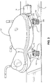
Figure 2 is perspective view of a refrigeration system with the compressor mounted to a support base member using the mounting arrangement of the present invention; -
Figure 3 is an enlarged perspective view of the mounted compressor ofFigure 2 ; -
Figure 4 is an upper perspective view of a vibration isolating mount employed in the mounting arrangement of the invention; -
Figure 5 is an elevational view of the vibration isolating mount ofFigure 4 ; -
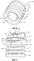
Figure 6 is a lower perspective view of the vibration isolating mount ofFigures 4 and 5 ; -
Figure 7 is an enlarged view of one mount fromFigure 3 ; and -
Figure 8 is a representative cross-sectional view of the mount ofFigure 7 . - With initial reference to
Figure 1 , a refrigerator is generally indicated at 2 and includes a cabinet defined, in part, by aside panel 4 and a top panel (not shown) which are generally formed from bending a single sheet of metal to which arear panel 6 and a bottom panel orsupport base member 7 are attached.Side panel 4 terminates at a forward end in a front in-turned flange 8, which is shown to have mounted thereto amounting bracket 11 for pivotally supporting a refrigerator door (not shown). As shown,refrigerator 2 includes a pair of spaced front leg members, one of which is indicated at 13, arranged at laterally spaced front portions (not separately labeled) of the cabinet. In addition,refrigerator 2 includes laterally spaced rear wheels, one of which is indicated at 14.Leg members 13 are preferably vertically adjustable to also act as levelers forcabinet 2, whilewheels 14 enhance the maneuverability ofrefrigerator 2. Such type of leg leveler and wheel support arrangements are widely known in the art of appliances, do not form part of the present invention and therefore will not be discussed further herein. -
Refrigerator 2 can take various forms, including top mount, bottom mount, side-by-side and French-style refrigerators. By way of example, as shown in these drawings, the cabinet ofrefrigerator 2 has mounted therein abottom panel unit 16 that includes a firsthorizontal portion 18, an upwardly and fore-to-aft sloping portion 20, and a second horizontal portion 22.Bottom panel unit 16,support base member 7 andrear panel 6 combine to define a mechanical compartment orchamber 24 which, in the embodiment shown, is arranged at a lower, rear portion ofrefrigerator 2. Mounted withinmechanical chamber 24 is a refrigeration system including acompressor 27 that is attached to anelongated plate 35. - In the embodiment shown,
support base member 7 includes first and second longitudinally spacedend portions lower surfaces support base member 7 is positioned at a bottom portion ofrefrigerator 2, it should be understood that, depending on the particular model or refrigerator type,support base member 7 could be re-positioned, even at an upper portion of the cabinet. In any event, the invention is concerned with mounting ofcompressor 27 to supportbase member 7 through the use of multiple vibration isolating mounts, one of which is generally indicated at 102 as described in detail below. - Prior to detailing the preferred construction of each
vibration isolating mount 102, reference is made toFigures 2 and3 in providing additional overall refrigeration system details. As best shown inFigure 2 , the refrigeration system is generally indicated at 150 and includes acontroller 155,compressor 27, acondenser 160 mounted in apan 165 arranged uponbase member 7 and afan 170. For purposes of simplicity of the drawings, the electrical wiring and fluid tubing associated withrefrigeration system 150 has been removed, although some wiring is shown inFigure 2 and some tubing inFigure 3 , though not labeled. - Reference will now be made to
Figures 4-6 in detailing the structure ofvibration isolating mount 102, which is employed to securecompressor 27 to supportbase member 7 in order to absorb vibrations produced during operation ofcompressor 27, in accordance with one preferred embodiment of the invention. In general,vibration isolating mount 102 is made of an elastomeric material so as to be deformable for shock absorbing purposes, yet resilient so as to readily rebound to its original configuration after deformation. The preferred material employed is EPDM. As depicted, eachmount 102 includes abase 200, a central body orcore 205, a plurality of vertically spaced, circumferential rings 210-212 projecting radially outward fromcentral body 205, and anupper head 215. For reasons detailed more fully below,base 200 andring 212 have a greater thickness or vertical dimension than either ofrings base 200 andring 210, as well as betweenring central body 205 are concave in shape, with these portions ofmount 102 establishing undercuts. As best shown inFigure 6 ,base 200 includes an annularflat portion 218 extending radially outwardly of a tapering androunded bottom portion 220 leading tocentral body 205. This figure, as well asFigure 4 , clearly illustrates thatcentral body 205 is provided with athrough hole 225. Mount 102 is also formed with amounting gap 240 betweenupper head 215 andring 212. In addition,upper head 215 has anupper surface 245 formed with an annular, arcuateperipheral edge portion 250 and from which project a plurality of spaced raised retention members 270-273 which taper from throughhole 225 toperipheral edge portion 250. - Although the particular order of mounting steps can be altered, the mounting of
compressor 27 inmechanical chamber 24 will now be detailed with main reference toFigure 3 ,7 and8 . As shown, eachelastomeric mount 102 is received in a respective opening, such as indicated at 285Figure 7 , in theelongated plate 35 such thatplate 35 becomes positioned within mounting gap 240 (noteplate 35 is missing fromFigure 8 for clarity purposes). The flexibility and tapered construction ofupper head 215 enhances this assembly procedure. Theelongated plate 35 is positioned above thesupport base member 7 and over a plurality ofpin elements 295 which extend through and are fixed to supportbase member 7, such as through a friction fit, threaded connection, welding or the like. Upon aligningpin elements 295 with throughholes 225, pinelements 295 are caused to project throughcentral body 205 ascompressor 27 is lowered untilcompressor 27 is supported bysupport base member 7 through the elastomeric mounts 102. Thereafter, a plurality ofretainers 300 are used to complete the mounting ofcompressor 27. - As perhaps best shown in
Figures 3 and8 , eachretainer 300 is constituted by a clip, including anupper leg 305, alower leg 310 and flexible connectingarms lower leg 310 includes anopening 325 receiving a respective one of the plurality ofpin elements 295, with each of thepin elements 295 being compressed onto a respectiveelastomeric mount 102 and against a respective set of retention members 270-273, e.g.,retention members Figure 8 . Eachlower leg 310 is also provided with opposing barbs (one of which is indicated at 330 inFigure 7 ) and extends intoopening 315, while engaging therespective pin element 295. Thereafter, eachupper leg 305 is snap-connected into anupper groove 325 of arespective pin element 295. - Based on this overall mounting arrangement, various advantageous vibration control features are established. In particular, the rounded bottom functions to pre-load the mounting arrangement and prevent vibration transmission through the cores of the mounts. In addition, the plurality of vertically spaced rings of each mount provide shock protection against a large impact force by deflecting and potentially contacting each other, while normal vertical isolation occurs by deflection of an uppermost ring. Furthermore, providing the various undercuts of the mounts allow the mounts to be optimized for the mass and operational frequency of the compressor. Finally, the inclusion of the retention members isolates clip retention and prevents the compressor from being constrained in the lateral and fore-to-aft directions. Overall, the mounting arrangement of the present invention provides an easy, cost-effective method of securing a compressor in a refrigerator while ensuring appropriate vibration isolation characteristics and mounting integrity.
- Although described with reference to preferred embodiments, it should be readily apparent to one of ordinary skill in the art that various changes and/or modifications can be made to the invention without departing from the spirit thereof. In addition, directional related terms, such as upper, lower, lateral, fore-to-aft and the like, as used in the written description are only intended to describe the invention with reference to the drawings such that these terms should not be limiting to the overall mounting arrangement. Finally, it should be realized that the invention is applicable to a wide range of cabinets employing refrigeration components, including dedicated freezer units and refrigerated vending machines. In general, the invention is only intended to be limited to the scope of the following claims.
Claims (11)
- A refrigerator comprising:a cabinet (2);at least one refrigeration compartment within the cabinet (2);a mechanical chamber (24) within the cabinet (2); anda refrigeration system (150) including a compressor (27) mounted within the mechanical chamber (24) through a mounting arrangement, characterized in that the mounting arrangement including:a support base member (7);a plurality of pin elements (295) extending from the support base member (7);an elongated plate (35) having a plurality of spaced openings, each of said plurality of openings being aligned with a respective one of the plurality of pin elements (295), said compressor (27) being attached to the elongated plate (35);a plurality of elastomeric mounts (102) each including a central body (205) established by a hollow core, a base (200) including a rounded bottom portion (220) leading to the central body (205), a plurality of vertically spaced rings (210-212) extending about the central body (205) and spaced by undercut portions, and an upper head (215) spaced from an adjacent one of the vertically spaced rings (210-212) by a mounting gap (240);a plurality of retainers (300), wherein each of the plurality of elastomeric mounts (102) is: a) attached to the elongated plate (35) with the upper head (215) extending through a respective one of the plurality of openings such that the elongated plate (35) is positioned within the mounting gap (240); b) positioned about a respective one of the plurality of pin elements (295) with the respective pin element (295) extending through the hollow core; c) and secured upon the support base member (7) by a respective one of the plurality of retainers (300) with the rounded bottom portion (220) of the base (200) being deformed to pre-load the mount (102).
- The refrigerator according to claim 1, wherein the base (200) is configured to minimize vibration transmission through the central body (205).
- The refrigerator according to claim 1, wherein an uppermost one of the plurality of rings (210-212) is configured to deflect and provide vertical isolation in response to vibrations developed during operation of the compressor (27).
- The refrigerator according to claim 1, wherein the plurality of rings (210-212) are configured to deflect and contact each other upon a large impact.
- The refrigerator according to claim 1, wherein the plurality of elastomeric mounts (102) are tuned through the undercut portions based on at least one of a mass and an operational frequency of the compressor (27).
- The refrigerator according to claim 1, wherein mounting of the compressor (27) through the plurality of retainers (300) prevents the compressor (27) from becoming constrained in both lateral and fore-to-aft directions.
- The refrigerator according to claim 6, wherein each said upper head (215) includes an upper surface (245) from which project a plurality of spaced raised retention members (270-273) for engaging a respective one of the plurality of retainers (300).
- The refrigerator according to claim 1, wherein the plurality of retainers (300) are constituted by clips, with each of the clips including an upper leg (305), a lower leg (310) and at least one connecting arm (315,316), with the lower leg (310) including an opening (325) receiving a respective one of the plurality of pin elements (295).
- The refrigerator according to claim 8, wherein the upper leg (305) of each of the clips also includes an opening receiving the respective one of the plurality of pin elements (295).
- The refrigerator according to claim 8, wherein each said upper head (215) includes an upper surface from which project a plurality of spaced raised retention members (270-273) and wherein the lower leg (310) of each of the clips engages a respective set of said plurality of raised retention members (270-273).
- The refrigerator according to claim 10, wherein each of said plurality of retainers (300) comprising at least one barb (330) extending from the lower leg (310) into the opening (315) in the lower leg (310) and engaging the respective one of the plurality of pin elements (295) to secure the retainer (300) on the respective one of the plurality of pin elements (295).
Applications Claiming Priority (1)
| Application Number | Priority Date | Filing Date | Title |
|---|---|---|---|
| US15/063,094 US10359225B2 (en) | 2016-03-07 | 2016-03-07 | Refrigerator vibration isolating compressor mount |
Publications (1)
| Publication Number | Publication Date |
|---|---|
| EP3217128A1 true EP3217128A1 (en) | 2017-09-13 |
Family
ID=58265817
Family Applications (1)
| Application Number | Title | Priority Date | Filing Date |
|---|---|---|---|
| EP17159740.4A Withdrawn EP3217128A1 (en) | 2016-03-07 | 2017-03-07 | Refrigerator vibration isolating compressor mount |
Country Status (2)
| Country | Link |
|---|---|
| US (2) | US10359225B2 (en) |
| EP (1) | EP3217128A1 (en) |
Cited By (1)
| Publication number | Priority date | Publication date | Assignee | Title |
|---|---|---|---|---|
| EP4394281A1 (en) * | 2022-12-29 | 2024-07-03 | Carrier Corporation | A mounting assembly for a refrigeration system |
Families Citing this family (14)
| Publication number | Priority date | Publication date | Assignee | Title |
|---|---|---|---|---|
| CN205689383U (en) * | 2016-05-18 | 2016-11-16 | 思科普压缩机(天津)有限公司 | Refrigeration compressor shell is installed to the system with the substrate in threaded hole |
| US10888173B2 (en) * | 2016-10-28 | 2021-01-12 | Sleep Number Corporation | Air controller with vibration isolators |
| KR102004047B1 (en) * | 2017-10-23 | 2019-07-25 | 엘지전자 주식회사 | A tray drip fir compact machine compartment and a refrigerator using the same |
| US10677480B2 (en) * | 2018-07-05 | 2020-06-09 | Therma-Stor, Llc | Portable dehumidifier |
| KR20200005087A (en) * | 2018-07-05 | 2020-01-15 | 주식회사 위니아대우 | Supportor, compressor including the same and refrigerator including the same |
| US10976063B2 (en) | 2019-02-19 | 2021-04-13 | Carrier Corporation | Vibration reducing grommet |
| US11391503B2 (en) * | 2019-03-26 | 2022-07-19 | Thaddeus Medical Systems, Inc. | Rotating pump mount and support for transportation enclosure |
| CN112129012A (en) * | 2020-08-31 | 2020-12-25 | 同济大学 | Closed vibrator, refrigerator and compressor |
| EP4261062A4 (en) * | 2020-12-11 | 2024-11-13 | Zhejiang Geely Holding Group Co., Ltd. | SUSPENSION SYSTEM FOR A VEHICLE AIR CONDITIONING COMPRESSOR AND VEHICLE |
| CN115217740A (en) * | 2021-04-16 | 2022-10-21 | 安徽美芝制冷设备有限公司 | Vibration Pads, Compressor Components and Refrigeration Equipment |
| US11832728B2 (en) * | 2021-08-24 | 2023-12-05 | Sleep Number Corporation | Controlling vibration transmission within inflation assemblies |
| US20230287958A1 (en) * | 2022-03-14 | 2023-09-14 | Carrier Corporation | Vibration isolating bracket for exhaust treatment unit |
| KR20230165052A (en) * | 2022-05-26 | 2023-12-05 | 삼성전자주식회사 | Compressor fastening apparatus |
| CN119533061A (en) * | 2023-08-31 | 2025-02-28 | 青岛海尔电冰箱有限公司 | Fixing device for refrigerator compressor, card and refrigerator |
Citations (9)
| Publication number | Priority date | Publication date | Assignee | Title |
|---|---|---|---|---|
| EP1043554A2 (en) * | 1999-04-08 | 2000-10-11 | Matsushita Electric Industrial Co., Ltd. | Refrigeration cycle apparatus |
| JP2002115744A (en) * | 2000-10-06 | 2002-04-19 | Nok Vibracoustic Kk | Vibration control mount |
| US20040168464A1 (en) * | 2003-02-28 | 2004-09-02 | Lg Electronics Inc. | Elastic member and vibration absorption apparatus for a refrigerator compressor |
| US20060216165A1 (en) * | 2004-12-17 | 2006-09-28 | Lg Electronics Inc. | Apparatus for mounting compressor |
| WO2007122235A1 (en) * | 2006-04-26 | 2007-11-01 | Tecumseh Europe S.A | Device for anchoring a refrigerating compressor. |
| WO2013111356A1 (en) * | 2012-01-25 | 2013-08-01 | ヤマウチ株式会社 | Support member for compressor, and compressor using same |
| JP2014055633A (en) * | 2012-09-12 | 2014-03-27 | Daikin Ind Ltd | Rubber vibration isolator for compressor |
| WO2015068754A1 (en) * | 2013-11-07 | 2015-05-14 | サンデン株式会社 | Structure for attaching electric compressor |
| CN105041611A (en) * | 2015-07-09 | 2015-11-11 | 合肥华凌股份有限公司 | Compressor foot pad and refrigerator |
Family Cites Families (19)
| Publication number | Priority date | Publication date | Assignee | Title |
|---|---|---|---|---|
| US3785167A (en) * | 1972-12-11 | 1974-01-15 | Amana Refrigeration Inc | Noise reduction means for connecting refrigerant compressors in air conditioners |
| US4490992A (en) * | 1983-12-29 | 1985-01-01 | General Electric Company | Household refrigerator compressor vibration isolator and condensate collecting tray |
| US5040953A (en) | 1988-09-19 | 1991-08-20 | Copeland Corporation | Mounting system |
| US4920696A (en) | 1989-02-03 | 1990-05-01 | While Consolidated Industries, Inc. | Refrigeration compressor mount |
| US5313806A (en) | 1992-01-09 | 1994-05-24 | Chun Feng | Integral air conditioner of which an indoor unit and an outdoor unit are connected with vibration dampers |
| JP3298213B2 (en) | 1993-03-17 | 2002-07-02 | 日産自動車株式会社 | Anti-vibration pad |
| US5306121A (en) * | 1993-04-23 | 1994-04-26 | Carrier Corporation | Compressor tiered mounting arrangement |
| KR200149414Y1 (en) * | 1996-12-27 | 1999-06-15 | 전주범 | Compressor fixing structure of the refrigerator |
| US5964579A (en) | 1997-06-24 | 1999-10-12 | Rheem Manufacturing Company | Prestressed resilient compressor mount apparatus |
| US6357717B1 (en) | 1999-04-01 | 2002-03-19 | Kennard Industries, Inc. | Vibration control device |
| KR100380653B1 (en) | 2000-09-05 | 2003-04-23 | 삼성전자주식회사 | Compressor assembly |
| DE10145145A1 (en) * | 2001-09-13 | 2003-04-03 | Bsh Bosch Siemens Hausgeraete | Vibration damping arrangement |
| US20040096341A1 (en) | 2002-11-19 | 2004-05-20 | Shinn Fu Corporation | Vibration and displacement proof air compressor |
| KR100565588B1 (en) | 2003-02-28 | 2006-03-29 | 엘지전자 주식회사 | Compressor mounting structure for refrigerator |
| US7735812B2 (en) * | 2003-04-30 | 2010-06-15 | Trelleborg Ab | Vibration-damping device |
| US6786298B1 (en) | 2003-05-13 | 2004-09-07 | Compal Electronics Inc. | Vibration-absorbing structure for support section of a self-vibratory electronic member |
| KR100546677B1 (en) | 2003-11-13 | 2006-01-26 | 엘지전자 주식회사 | Anti-vibration Rubber for Compressors |
| US7278834B2 (en) | 2004-01-20 | 2007-10-09 | Tecumseh Products Company | Compressor assemblies with improved mounting support and method of mounting such compressor assemblies |
| EP2341179B1 (en) | 2009-12-29 | 2017-04-19 | Electrolux Home Products Corporation N.V. | Home laundry drier |
-
2016
- 2016-03-07 US US15/063,094 patent/US10359225B2/en active Active
-
2017
- 2017-03-07 EP EP17159740.4A patent/EP3217128A1/en not_active Withdrawn
-
2019
- 2019-06-06 US US16/433,766 patent/US10859306B2/en active Active
Patent Citations (9)
| Publication number | Priority date | Publication date | Assignee | Title |
|---|---|---|---|---|
| EP1043554A2 (en) * | 1999-04-08 | 2000-10-11 | Matsushita Electric Industrial Co., Ltd. | Refrigeration cycle apparatus |
| JP2002115744A (en) * | 2000-10-06 | 2002-04-19 | Nok Vibracoustic Kk | Vibration control mount |
| US20040168464A1 (en) * | 2003-02-28 | 2004-09-02 | Lg Electronics Inc. | Elastic member and vibration absorption apparatus for a refrigerator compressor |
| US20060216165A1 (en) * | 2004-12-17 | 2006-09-28 | Lg Electronics Inc. | Apparatus for mounting compressor |
| WO2007122235A1 (en) * | 2006-04-26 | 2007-11-01 | Tecumseh Europe S.A | Device for anchoring a refrigerating compressor. |
| WO2013111356A1 (en) * | 2012-01-25 | 2013-08-01 | ヤマウチ株式会社 | Support member for compressor, and compressor using same |
| JP2014055633A (en) * | 2012-09-12 | 2014-03-27 | Daikin Ind Ltd | Rubber vibration isolator for compressor |
| WO2015068754A1 (en) * | 2013-11-07 | 2015-05-14 | サンデン株式会社 | Structure for attaching electric compressor |
| CN105041611A (en) * | 2015-07-09 | 2015-11-11 | 合肥华凌股份有限公司 | Compressor foot pad and refrigerator |
Cited By (1)
| Publication number | Priority date | Publication date | Assignee | Title |
|---|---|---|---|---|
| EP4394281A1 (en) * | 2022-12-29 | 2024-07-03 | Carrier Corporation | A mounting assembly for a refrigeration system |
Also Published As
| Publication number | Publication date |
|---|---|
| US10359225B2 (en) | 2019-07-23 |
| US20190285333A1 (en) | 2019-09-19 |
| US10859306B2 (en) | 2020-12-08 |
| US20170254582A1 (en) | 2017-09-07 |
Similar Documents
| Publication | Publication Date | Title |
|---|---|---|
| US10859306B2 (en) | Refrigerator vibration isolating compressor mount | |
| KR101784922B1 (en) | Earthquake-resistatnt type of hanger apparatus for cable tray and cable tray including the same | |
| US5913892A (en) | Compressor fixture structure for a refrigerator | |
| US5306121A (en) | Compressor tiered mounting arrangement | |
| US5544714A (en) | Quick-connect fastener and vibration isolator unit for attachment of automotive components | |
| KR100548308B1 (en) | Compressor Support of Refrigerator | |
| CN103597242B (en) | Vibration isolation systems for roof-mounted HVAC equipment | |
| RU2664298C2 (en) | Domestic refrigeration appliance comprising a compressor having compressor feet | |
| JP2013148236A (en) | Outdoor unit of air conditioner, and outdoor unit mounted with compressor with vibration isolator and so forth | |
| US4461446A (en) | Hermetic refrigeration compressor installation and method | |
| KR200461509Y1 (en) | Supporting device of compressor | |
| US3292884A (en) | Hermetic compressor mounting system | |
| JP2002031056A (en) | Compressor support device | |
| JP2008292062A (en) | Refrigerant container fixing device for compressor piping | |
| US3138358A (en) | Support structure | |
| EP2781746A1 (en) | Vibration-reducing support structure for compressor | |
| CN113260789A (en) | Compressor and support member for compressor | |
| KR100608672B1 (en) | Compressor Support of Refrigerator | |
| JP2005180648A (en) | Mounting structure of heat exchanger | |
| KR20110043252A (en) | Dustproof device of compressor for air conditioner | |
| US20090256032A1 (en) | Device for Vibration-Damping Fastening of at Least One Object to a Support Element | |
| JPS634932Y2 (en) | ||
| CN114251247A (en) | Buffer structure, compressor and refrigeration plant | |
| CN109798237A (en) | refrigerator | |
| CN217927833U (en) | Shock attenuation mounting structure of fan |
Legal Events
| Date | Code | Title | Description |
|---|---|---|---|
| PUAI | Public reference made under article 153(3) epc to a published international application that has entered the european phase |
Free format text: ORIGINAL CODE: 0009012 |
|
| STAA | Information on the status of an ep patent application or granted ep patent |
Free format text: STATUS: THE APPLICATION HAS BEEN PUBLISHED |
|
| AK | Designated contracting states |
Kind code of ref document: A1 Designated state(s): AL AT BE BG CH CY CZ DE DK EE ES FI FR GB GR HR HU IE IS IT LI LT LU LV MC MK MT NL NO PL PT RO RS SE SI SK SM TR |
|
| AX | Request for extension of the european patent |
Extension state: BA ME |
|
| STAA | Information on the status of an ep patent application or granted ep patent |
Free format text: STATUS: THE APPLICATION IS DEEMED TO BE WITHDRAWN |
|
| 18D | Application deemed to be withdrawn |
Effective date: 20180314 |