EP3217096A1 - Exhaust duct and boiler - Google Patents
Exhaust duct and boiler Download PDFInfo
- Publication number
- EP3217096A1 EP3217096A1 EP15866675.0A EP15866675A EP3217096A1 EP 3217096 A1 EP3217096 A1 EP 3217096A1 EP 15866675 A EP15866675 A EP 15866675A EP 3217096 A1 EP3217096 A1 EP 3217096A1
- Authority
- EP
- European Patent Office
- Prior art keywords
- section
- flue gas
- hopper
- repulsion
- low
- Prior art date
- Legal status (The legal status is an assumption and is not a legal conclusion. Google has not performed a legal analysis and makes no representation as to the accuracy of the status listed.)
- Granted
Links
Images




Classifications
-
- F—MECHANICAL ENGINEERING; LIGHTING; HEATING; WEAPONS; BLASTING
- F23—COMBUSTION APPARATUS; COMBUSTION PROCESSES
- F23J—REMOVAL OR TREATMENT OF COMBUSTION PRODUCTS OR COMBUSTION RESIDUES; FLUES
- F23J3/00—Removing solid residues from passages or chambers beyond the fire, e.g. from flues by soot blowers
- F23J3/04—Traps
-
- B—PERFORMING OPERATIONS; TRANSPORTING
- B01—PHYSICAL OR CHEMICAL PROCESSES OR APPARATUS IN GENERAL
- B01D—SEPARATION
- B01D45/00—Separating dispersed particles from gases or vapours by gravity, inertia, or centrifugal forces
- B01D45/04—Separating dispersed particles from gases or vapours by gravity, inertia, or centrifugal forces by utilising inertia
-
- F—MECHANICAL ENGINEERING; LIGHTING; HEATING; WEAPONS; BLASTING
- F23—COMBUSTION APPARATUS; COMBUSTION PROCESSES
- F23J—REMOVAL OR TREATMENT OF COMBUSTION PRODUCTS OR COMBUSTION RESIDUES; FLUES
- F23J15/00—Arrangements of devices for treating smoke or fumes
- F23J15/02—Arrangements of devices for treating smoke or fumes of purifiers, e.g. for removing noxious material
- F23J15/022—Arrangements of devices for treating smoke or fumes of purifiers, e.g. for removing noxious material for removing solid particulate material from the gasflow
-
- F—MECHANICAL ENGINEERING; LIGHTING; HEATING; WEAPONS; BLASTING
- F23—COMBUSTION APPARATUS; COMBUSTION PROCESSES
- F23M—CASINGS, LININGS, WALLS OR DOORS SPECIALLY ADAPTED FOR COMBUSTION CHAMBERS, e.g. FIREBRIDGES; DEVICES FOR DEFLECTING AIR, FLAMES OR COMBUSTION PRODUCTS IN COMBUSTION CHAMBERS; SAFETY ARRANGEMENTS SPECIALLY ADAPTED FOR COMBUSTION APPARATUS; DETAILS OF COMBUSTION CHAMBERS, NOT OTHERWISE PROVIDED FOR
- F23M5/00—Casings; Linings; Walls
-
- B—PERFORMING OPERATIONS; TRANSPORTING
- B01—PHYSICAL OR CHEMICAL PROCESSES OR APPARATUS IN GENERAL
- B01D—SEPARATION
- B01D45/00—Separating dispersed particles from gases or vapours by gravity, inertia, or centrifugal forces
- B01D45/04—Separating dispersed particles from gases or vapours by gravity, inertia, or centrifugal forces by utilising inertia
- B01D45/08—Separating dispersed particles from gases or vapours by gravity, inertia, or centrifugal forces by utilising inertia by impingement against baffle separators
-
- F—MECHANICAL ENGINEERING; LIGHTING; HEATING; WEAPONS; BLASTING
- F23—COMBUSTION APPARATUS; COMBUSTION PROCESSES
- F23J—REMOVAL OR TREATMENT OF COMBUSTION PRODUCTS OR COMBUSTION RESIDUES; FLUES
- F23J2217/00—Intercepting solids
- F23J2217/20—Intercepting solids by baffles
-
- F—MECHANICAL ENGINEERING; LIGHTING; HEATING; WEAPONS; BLASTING
- F23—COMBUSTION APPARATUS; COMBUSTION PROCESSES
- F23J—REMOVAL OR TREATMENT OF COMBUSTION PRODUCTS OR COMBUSTION RESIDUES; FLUES
- F23J2217/00—Intercepting solids
- F23J2217/30—Intercepting solids by screens
Definitions
- the present invention relates to an exhaust duct which is applied to a boiler which generates steam for power generation, a factory, or the like, and a boiler including the exhaust duct.
- a pulverized coal fired boiler includes a furnace which has a hollow shape and is installed in a vertical direction, and a plurality of combustion burners are disposed on a wall of the furnace along a circumferential direction and are arranged in a plurality of stages in an upward-downward direction.
- a gaseous mixture of pulverized coal (fuel) which is crushed coal and transport air (primary air) is supplied to the combustion burner, high-temperature secondary air is supplied to the combustion burner, flames are generated by blowing the gaseous mixture and the secondary gas into the furnace, and combustion gas can be generated in the furnace.
- a flue gas duct is connected to the upper portion of the furnace, a superheater, a reheater, an economizer, or the like for collecting heat of a flue gas is provided in the flue gas duct, water is heated by an exhaust gas generated by combustion in the furnace, and steam can be generated.
- a flue gas duct is connected to the flue gas duct, a denitration device, an electric dust collector, a desulfurization device, or the like is provided in the flue gas duct, and a funnel is provided on a downstream end portion of the flue gas duct.
- boiler there are boilers which are disclosed in PTLs below.
- popcorn ashes massesive ashes which solid particles may be mixed into the flue gas. Since the popcorn ashes are lumps of ashes, particularly, the popcorn ashes block a screen, a denitration device, or the like provided in a flue gas duct. Accordingly, the screen is abraded and needs so as to be exchanged, and a maintenance cost increases. In addition, the popcorn ashes are accumulated on the screen or the denitration device, pressure loss increases, and performance decreases. Moreover, in a flue gas treatment device of PTL 2, a popcorn-ash-trapping section is provided on the downstream side of a hopper. However, there is a concern that the popcorn-ash-trapping section may be damaged by collision of the popcorn ashes due to a long-term use.
- the present invention is made to solve the above-described problems, and an object thereof is to provide an exhaust duct and a boiler in which solid particles in a flue gas can be appropriately trapped.
- an exhaust duct including: a flue gas duct through which a flue gas flows; a hopper which is provided in the flue gas duct and collects solid particles in the flue gas; a low-repulsion section which is provided on an upstream side or a downstream side of the hopper in a direction of flow of the flue gas and has a lower coefficient of repulsion than that of an inner wall surface of the flue gas duct; and a solid particle trapping section which is provided on downstream sides of the hopper and the low-repulsion section in the direction of flow of the flue gas and traps solid particles in the flue gas.
- the solid particles are separated from the flue gas and collected in the hopper.
- the solid particles have an inertial force
- the solid particles collide with the inner wall surface of the flue gas duct are not collected in the hopper, and easily flow to the downstream side.
- the solid particles collide with the low-repulsion section repulsion amounts of the solid particles decrease and the solid particles are appropriately collected in the hopper.
- the solid particles which are not collected in the hopper and flow to the downstream side are trapped by the solid particle trapping section. As a result, it is possible to appropriately trap the solid particles in the flue gas in the hopper and it is possible to improve trapping efficiency.
- the flue gas duct includes a first vertical section through which the flue gas flows downward in a vertical direction and a horizontal section which is connected to the first vertical section, the hopper is provided below a connection section between the first vertical section and the horizontal section, and the low-repulsion section is provided on the lower wall surface section in the first vertical section on the upstream side of the hopper in the direction of flow of the flue gas.
- the low-repulsion section is provided on the upstream side of the hopper, the solid particles included in the flue gas collide with the low-repulsion section before the hopper, the inertial force of the solid particles decreases, and the solid particles easily enter the hopper. Accordingly, it is possible to decrease the amount of the solid particles which jump over the hopper and are scattered toward the downstream side to flow out.
- the low-repulsion section includes an inclination surface which is inclined in the same direction as that of an inclination surface of the hopper.
- the inclination surface of the low-repulsion section and the inclination surface of the hopper are inclined in the same direction, if the solid particles included in the flue gas collide with the low-repulsion section, the solid particles fall along the inclination surface of the hopper from the inclination surface of the low-repulsion section so as to be collected in the hopper, and it is possible to appropriately introduce the solid particles to the hopper.
- the inclination surface of the low-repulsion section extends to the inclination surface of the hopper.
- the low-repulsion section extends to the hopper, the inertial force of the solid particles is appropriately decreased by the low-repulsion section so as to easily enter the hopper, and it is possible to prevent the solid particles from being scattered from the hopper again.
- the lower wall surface section of the first vertical section includes an inclination surface and a horizontal surface arranged in the direction of flow of the flue gas, and the low-repulsion section is provided from the inclination surface to the horizontal surface.
- the low-repulsion section is provided from the inclination surface to the horizontal surface, the low-repulsion section is formed to extend in the direction of flow of the flue gas and the horizontal surface by which the inertial force of the solid particles can be decreased is formed. Therefore, the solid particles easily enter the hopper and it is possible to prevent the solid particles from being scattered from the hopper again.
- the solid particle trapping section is provided in the vertical direction.
- the solid particle trapping section is provided so as to be inclined such that the upper portion is positioned on the upstream side in the direction of flow of the flue gas.
- the solid particle trapping section is provided so as to be inclined on the upstream side, the solid particle trapping section causes the solid particles which are not collected in the hopper and flow to the downstream side to effectively fall into the hopper to trap the solid particles.
- the solid particle trapping section is provided in a region of 30% to 50% of the entire height of the flue gas duct from the lower wall surface section in the horizontal section.
- the solid particle trapping section is provided in only the region to which the solid particles which are not collected in the hopper easily flow out, it is possible to reduce the size and the cost of the solid particle trapping section.
- the solid particle trapping section is provided in a region of 100% of the entire height of the flue gas duct.
- the solid particle trapping section is provided on the entire region of the exhaust duct, it is possible to more reliably trap the solid particles, which are not collected in the hopper and flow to the downstream side, by the solid particle trapping section.
- the flue gas duct includes a horizontal section through which the flue gas flows in a horizontal direction and a second vertical section which is connected to the horizontal section and through which the flue gas flows upward in a vertical direction, the hopper is provided below a connection section between the horizontal section and the second vertical section, and the low-repulsion section is provided on a standing wall surface section in the second vertical section facing the horizontal section on the downstream side of the hopper in the direction of flow of the flue gas.
- the low-repulsion section is provided on the downstream side of the hopper, since the solid particles included in the flue gas passes through the upper portion of the hopper and thereafter, collide with the low-repulsion section, the inertial force of the solid particles decreases and the solid particles easily enter the hopper. Therefore, it is possible to decrease the amounts of the solid particles which jump over the hopper and are scattered toward the downstream side so as to flow out.
- the solid particle trapping section is provided in the horizontal direction.
- the solid particle trapping section is provided in a region of 30% to 50% of a horizontal length of the second vertical section from the standing wall surface section in the second vertical section facing the horizontal section.
- the solid particle trapping section is provided in only the region to which the solid particles which are not collected in the hopper easily flow out, it is possible to reduce the size and the cost of the solid particle trapping section.
- a boiler including: a furnace which has a hollow shape and is installed in a vertical direction; combustion equipment which blows a fuel toward the inner portion of the furnace and combusts the fuel; the exhaust duct which is connected to a downstream side in a direction of flow of a flue gas in the furnace; and a heat collection section which is provided in the exhaust duct and can collect heat in the flue gas.
- the low-repulsion section having a lower coefficient of repulsion than that of an inner wall surface of the flue gas duct is provided on the upstream side or the downstream side of the hopper and the solid particle trapping section is provided on the downstream sides of the hopper and the low-repulsion section, it is possible to appropriately trap the solid particles of the flue gas in the hopper and it is possible to improve trapping efficiency.
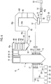
- Fig. 6 is a schematic configuration view showing a pulverized coal fired boiler to which an exhaust duct of a first embodiment is applied.
- the pulverized coal fired boiler to which the exhaust duct of the first embodiment is applied is a boiler in which pulverized coal which is crushed coal is used as a solid fuel, the pulverized coal is combusted by a combustion burner, and heat generated by the combustion can be collected.
- the pulverized coal fired boiler is applied.
- the boiler is not limited to the pulverized coal fired boiler, and the fuel is not limited to the coal.
- a pulverized coal fired boiler 10 is a conventional boiler, and includes a furnace 11 and combustion equipment 12.
- the furnace 11 has a square cylindrical hollow shape and is installed along a vertical direction, and the combustion equipment 12 is provided on a lower portion of a furnace wall configuring the furnace 11.
- the combustion equipment 12 includes a plurality of combustion burners 21, 22, 23, 24, and 25 which are mounted on the furnace wall.
- the combustion burners 21, 22, 23, 24, and 25 four burners which are arranged with equal intervals therebetween in a circumferential direction are set to one set, and five sets of burners, that is, five stages of burners are disposed in the vertical direction.
- each of the combustion burners 21, 22, 23, 24, and 25 is connected to each of coal pulverizers (mills) 31, 32, 33, 34, and 35 via each of pulverized coal supply pipes 26, 27, 28, 29, and 30.
- a crushing table is supported so as to be driven and rotated around a rotational axis along a vertical direction in a housing, and a plurality of crushing rollers facing the upper portion of the crushing table are rotatably supported so as to interlock with the rotation of the crushing table.
- coal is input to a portion between the plurality of crushing rollers and the crushing table, here, the coal is crushed so as to be a predetermined size, and it is possible to supply pulverized coal classified by a transport air (primary air) from the pulverized coal supply pipes 26, 27, 28, 29, and 30 to the combustion burners 21, 22, 23, 24, and 25.
- a transport air primary air
- a wind box 36 is provided on the mounting position of each of the combustion burners 21, 22, 23, 24, and 25, one end portion of an air duct 37 is connected to the wind box 36, and a blower 38 is mounted on the other end portion of the air duct 37. Accordingly, combustion air (secondary air and tertiary air) fed by the blower 38 is supplied from the air duct 37 to the wind box 36, and the combustion air can be supplied from the wind box 36 to each of the combustion burners 21, 22, 23, 24, and 25.
- each of the combustion burners 21, 22, 23, 24, and 25 can blow a pulverized fuel-gas mixture (fuel gas), in which the pulverized coal and the primary air are mixed with each other, into the furnace 11, can blow the secondary air into the furnace 11, and can form flames by igniting the pulverized fuel-gas mixture using an ignition torch (not shown).
- a pulverized fuel-gas mixture fuel gas
- an ignition torch not shown
- each of the combustion burners 21, 22, 23, 24, and 25 forms flames by injecting fuel oil into the furnace 11.
- a flue gas duct 40 is connected to the upper portion of furnace 11, and superheaters 41 and 42 for collecting the heat of the flue gas, reheaters 43 and 44, and economizers 45, 46, and 47 which are convection heat transfer portions (heat collection sections) are provided in the flue gas duct 40, and heat exchange is performed between the flue gas generated by the combustion of the furnace 11 and water.
- a flue gas pipe (flue gas duct) 48 through which the flue gas subjected to the heat exchange is discharged is connected to the downstream side of the flue gas duct 40.
- An air heater 49 is provided between the flue gas pipe 48 and the air duct 37, heat exchange between air flowing through the air duct 37 and the flue gas flowing through the flue gas pipe 48 is performed, and it is possible to increase temperature of the combustion air supplied to the combustion burners 21, 22, 23, 24, and 25.
- a selective reduction type catalyst 50 is provided at the position on the upstream side of the air heater 49, an ash dust processing device (electric dust collector, desulfurization device) 51 and an induced blower 52 are provided at the position on the downstream side of the air heater 49, and a funnel 53 is provided on the downstream end portion of the flue gas pipe 48.
- the selective reduction type catalyst 50 and the electric ash dust processing device 51 function as a harmful matter removing portion.
- the produced pulverized coal is supplied to the combustion burners 21, 22, 23, 24, and 25 through the pulverized coal supply pipes 26, 27, 28, 29, and 30 along with the transport air.
- the heated combustion air is supplied from the air duct 37 to each of the combustion burners 21, 22, 23, 24, and 25 via the wind box 36. Accordingly, the combustion burners 21, 22, 23, 24, and 25 blow the pulverized fuel-gas mixture, in which the pulverized coal and the transport air are mixed with each other, into the furnace 11 and blow the combustion air into the furnace 11, and at this time, it is possible to form flames by performing ignition.
- the pulverized fuel-gas mixture and the combustion air are combusted, flames are generated, and if flames are generated at the lower portion inside the furnace 11, the combustion gas (flue gas) rises in the furnace 11 and is discharged to the flue gas duct 40.
- the water is supplied to a steam drum (not shown) and is heated so as to be saturated steam while being supplied to the water pipes (not shown) of the furnace wall, and the saturated steam is transported to a steam drum (not shown).
- the saturated steam of the steam drum (not shown) is introduced into the superheaters 41 and 42 so as to be superheated by the combustion gas.
- the superheated steam generated by the superheaters 41 and 42 is supplied to a power generation plant (not shown) (for example, a turbine or the like).
- the steam which is extracted in the middle of an expansion process in the turbine, is introduced into the reheaters 43 and 44, is superheated again, and is returned to the turbine.
- the drum (steam drum) type furnace 11 is described.
- the present invention is not limited to this structure.
- harmful materials such as NOx of the flue gas passing through the economizers 45, 46, and 47 of the flue gas duct 40 are removed by the selective reduction type catalyst 50 in the flue gas pipe 48, particle materials and the sulfur contents are removed by the ash dust processing device 51, and thereafter, the flue gas is discharged from the funnel 53 to the atmosphere.
- the flue gas duct 40 on the downstream side of the furnace 11 functions as the exhaust duct of the first embodiment.
- a first horizontal flue gas duct section (first vertical section) 40a, a first vertical flue gas duct section 40b, a second horizontal flue gas duct section (horizontal section) 40c, a second vertical flue gas duct section (second vertical section) 40d, a third horizontal flue gas duct section 40e, a third vertical flue gas duct section 40f, and a fourth horizontal flue gas duct section 40g are continuously provided.
- a kicker 54 is provided on the inner side of a connection section between the first vertical flue gas duct section 40b and the second horizontal flue gas duct section 40c in the horizontal direction.
- the superheaters 41 and 42, the reheaters 43 and 44, and the economizers 45, 46, and 47 are disposed in the first horizontal flue gas duct section 40a and the first vertical flue gas duct section 40b.
- a first hopper 61 is installed on the lower end portion of the first vertical flue gas duct section 40b through which the flue gas having a downward velocity component flows
- a second hopper 65 is installed on the lower end portion of the second vertical flue gas duct section 40d through which the flue gas having an upward velocity component flows.
- the selective reduction type catalyst 50 is installed in the third vertical flue gas duct section 40f through which the flue gas flows downward.
- Fig. 1 is a side view showing the exhaust duct of the first embodiment
- Fig. 2 is a sectional view taken along line II-II of Fig. 1 showing the exhaust duct.
- the exhaust duct of the first embodiment includes a flue gas duct 60 through which a flue gas flows, the first hopper 61 which is provided in the flue gas duct 60 and in which solid particles in the flue gas are collected, a low-repulsion section 62 which is provided on the upstream side of the first hopper 61 in the direction of flow of the flue gas and has a lower coefficient of repulsion than that of the inner wall surface of the flue gas duct 60, and a popcorn-ash-trapping section (solid particle trapping section) 63 which is provided on the downstream sides of the first hopper 61 and the low-repulsion section 62 in the direction of flow of the flue gas and traps popcorn ashes (solid particles and hereinafter, referred to as PA) in the flue gas.
- a flue gas duct 60 through which a flue gas flows
- the first hopper 61 which is provided in the flue gas duct 60 and in which solid particles in the flue gas are collected
- a low-repulsion section 62
- the flue gas duct 60 includes a first vertical flue gas duct section 40b through which the flue gas duct gas flows downward in the vertical direction and the second horizontal flue gas duct section 40c which is connected to the first vertical flue gas duct section 40b and through which the flue gas flows in the horizontal direction, and the first hopper 61 is provided below the connection section of the first vertical flue gas duct section 40b and the second horizontal flue gas duct section 40c.
- a lower wall surface section 71 is provided below the first vertical flue gas duct section 40b, and the lower wall surface section 71 is an inclination surface which is inclined downward at a predetermined angle toward the second horizontal flue gas duct section 40c side and the first hopper 61 side.
- a lower wall surface section 72 is provided below the second horizontal flue gas duct section 40c, and the lower wall surface section 72 is a horizontal surface positioned in the horizontal direction.
- the first hopper 61 mainly collects and stores the PA which is ashes having large diameters as the solid particles included in the flue gas.
- the first hopper 61 includes a first inclination surface 73 and a second inclination surface 74 which face each other in the flow direction of the flue gas such that an area of the first hopper 61 decreases downward, and a storage section 75 is provided on a bottom position at which the lower end portions of the inclination surfaces 73 and 74 are connected to each other.
- an opening portion which can be opened and closed by an on-off valve (not shown) is provided in the storage section 75, and the stored PA can be discharged downward by opening the opening portion.
- the lower wall surface section 71 of the first vertical flue gas duct section 40b and the first inclination surface 73 of the first hopper 61 are connected to each other so as to be surfaces which are continued at approximately the same inclination angle.
- the angles of the lower wall surface section 71 and the first inclination surface 73 are set so as to be equal to or more than a repose angle such that the PA is dropped.
- the second inclination surface 74 of the first hopper 61 and the second horizontal flue gas duct section 40c are connected so as to be bent at a predetermined angle.
- the low-repulsion section 62 is provided on the lower wall surface section 71 in the first vertical flue gas duct section 40b on the upstream side of the first hopper 61 in the direction of flow of the flue gas. Since the lower wall surface section 71 of the first vertical flue gas duct section 40b is an inclination surface, the surface of the low-repulsion section 62 becomes an inclination surface 62a and has approximately the same angle as that of the first inclination surface 73.
- the low-repulsion section 62 has a sheet shape having a predetermined area, is fixed to the lower wall surface section (inclination surface) 71 in the first vertical flue gas duct section 40b, and is configured of a member having a lower coefficient of repulsion than that of the lower wall surface section 71 (for example, steel plate) to effectively improve trapping efficiency of the PA in the first hopper 61. Accordingly, when the PA falls along the low-repulsion section 62, since the PA falls while coming into contact with the inclination surface 62a, the repulsion amount of the PA is decreased when the PA collides with the low-repulsion section 62.
- the PA since the PA which falls along with the downward flue gas G directly collides with the low-repulsion section 62, the PA is repulsed so as to be smaller than the repulsion amount of the PA when the PA directly collides with the lower wall surface section 71 which is a steel plate, a probability of the PA jumping over the first hopper 61 and being scattered toward the lower wall surface section 72 of the second horizontal flue gas duct section 40c is reduced, and the trapping efficiency of the PA in the first hopper 61 is improved.
- Fig. 3 is a perspective view showing the low-repulsion structure section which is provided in the exhaust duct
- Figs. 4 and 5 are schematic views showing effects of the low-repulsion structure section.
- the low-repulsion section 62 includes a wire netting (low-repulsion section formation member) 81 and a pair of frame bodies 82 which supports the wire netting 81 from both sides. Since the wire netting 81 is disposed so as to float by a predetermined height with respect to the lower wall surface section (inclination surface) 71 of a steel-plate duct by the pair of frame bodies 82, a space section 83 is formed between the lower wall surface section (inclination surface) 71 and the wire netting. In addition, a plurality of opening portions 84 serving as the passage of the PA are provided in the wire netting 81. Accordingly, as shown in Fig.
- the PA which falls downward in the vertical direction passes through the opening portions 84 of the wire netting 81 and collides with the lower wall surface section (inclination surface) 71 so as to be repulsed.
- the PA is likely to collide with the back face side of the wire netting 81 again.
- the PA which collides with the back face side of the wire netting 81 falls into the space section 83 along the lower wall surface section (inclination surface) 71, and finally is collected in the first hopper 61.
- the PA may collide with the wire netting 81 in which linear members are combined in a lattice shape.
- the PA which collides with the linear members of the wire netting 81 collides with a member which has a lower coefficient of repulsion than that of a general steel plate and is easily elastic-deformed, and as a result, the repulsion amount of the PA decreases, and the PA is likely to be collected in the first hopper 61.
- the low-repulsion section 62 is wire netting 81.
- the low-repulsion section 62 is not limited to this.
- a lattice-shaped member such as a grating, a porous plate, or a bamboo blind structure (slatted shutter) may be used, which includes a plurality of opening portions having sizes in which the PA can pass through.
- the lattice-shaped low-repulsion member formed of a material which collides with the PA and is elastically deformed is adopted, collision energy of the PA due to elastic deformation is effectively absorbed, and it is possible to decrease the repulsion amount.
- the repulsion amount can be decreased.
- the low-repulsion section 62 is not limited to the porous member, and as the low-repulsion section 62, a heat insulation material, a rubber material, a plastic material, or the like which is not porous may be adopted.
- the popcorn-ash-trapping section 63 traps the PA in the flue gas which cannot be collected by the first hopper 61.
- the popcorn-ash-trapping section 63 is formed of a wire netting having a mesh shape, and for example, is configured of a plurality of openings in which one side is set to 2 mm to 3 mm or less.
- the popcorn-ash-trapping section 63 is not limited to the wire netting having a mesh shape, and may be a screen or a porous body having vertical slits or horizontal slits.
- the second horizontal flue gas duct section 40c has a rectangular cross section, and is configured such that side wall surface portions (vertical surfaces) 76 are formed on both sides of the lower wall surface section (horizontal surface) 72 and an upper wall surface portion (horizontal surface) 77 is formed on each side wall surface portion 76.
- the popcorn-ash-trapping section 63 is provided on the lower wall surface section (horizontal surface) 72 in the vertical direction. Moreover, the popcorn-ash-trapping section 63 is provided at a height H1 of a region from 30% to 50% of the entire height H from the lower wall surface section (horizontal surface) to the second horizontal flue gas duct section 40c.
- the popcorn-ash-trapping section 63 is provided on a region from 30% to 50% in a passage area of the flue gas duct 60. That is, the first vertical flue gas duct section 40b and the second horizontal flue gas duct section 40c are connected to each other so as to be bent 90°, the upstream end portion of the second horizontal flue gas duct section 40c, that is, the outer peripheral side of the region immediately after the first hopper 61 is blocked by the popcorn-ash-trapping section 63.
- the flue gas moves downward along the first vertical flue gas duct section 40b, is curved so as to be approximately perpendicular to the first vertical flue gas duct section 40b, and flows into the second horizontal flue gas duct section 40c.
- the PA included in the flue gas G freely falls so as to be stored in the first hopper 61.
- the PA which collides with the lower end portion of the low-repulsion section 62 collides with the low-repulsion section 62, and the repulsion force of the PA decreases.
- the PA may jump over the first hopper 61.
- the popcorn-ash-trapping section 63 is provided at the inlet portion of the second horizontal flue gas duct section 40c, the PA which collides with the low-repulsion section 62 and jumps over the first hopper 61 collides with the popcorn-ash-trapping section 63. Accordingly, the PA is trapped by the popcorn-ash-trapping section 63 or falls so as to be collected in the first hopper 61.
- the flue gas duct 60 through which the flue gas flows the first hopper 61 which is provided in the flue gas duct 60 and in which the PA in the flue gas is collected, the low-repulsion section 62 which is provided on the upstream side of the first hopper 61 in the direction of flow of the flue gas and has a lower coefficient of repulsion than that of the inner wall surface of the flue gas duct 60, and the popcorn-ash-trapping section 63 which is provided on the downstream sides of the first hopper 61 and the low-repulsion section 62 in the direction of flow of the flue gas and traps the PA in the flue gas are provided.
- the PA is separated from the flue gas G and collected in the first hopper 61.
- the PA since the PA has the inertial force, the PA collides with the inner wall surface of the flue gas duct 60, is not collected in the first hopper 61, and easily flows to the downstream side.
- the PA collides with the low-repulsion section 62 the repulsion amount of the PA decrease and the PA is appropriately collected in the first hopper 61.
- the PA which is not collected in the first hopper 61 and flows to the downstream side is trapped by the popcorn-ash-trapping section 63. As a result, it is possible to appropriately trap the PA in the flue gas G in the first hopper 61 and it is possible to improve trapping efficiency.
- the flue gas duct 60 includes the first vertical flue gas duct section 40b through which the flue gas G flows downward in a vertical direction and the second horizontal flue gas duct section 40c which is connected to the first vertical flue gas duct section 40b, the first hopper 61 is provided below the connection section between the first vertical flue gas duct section 40b and the second horizontal flue gas duct section 40c, and the low-repulsion section 62 is provided on the lower wall surface section 71 in the first vertical flue gas duct section 40b on the upstream side of the first hopper 61 in the direction of flow of the flue gas.
- the low-repulsion section 62 is provided on the upstream side of the first hopper 61, the PA included in the flue gas G collides with the low-repulsion section 62 before the first hopper 61, the inertial force of the PA decreases, and the PA easily enters the first hopper 61. Accordingly, it is possible to decreases the amount of the PA which jumps over the first hopper 61 and is scattered toward the downstream side to flow out.
- the low-repulsion section 62 includes the inclination surface which is inclined in the same direction as that of the first inclination surface 73 of the first hopper 61. Accordingly, if the PA included in the flue gas G collides with the low-repulsion section 62, the PA falls along the first inclination surface 73 of the first hopper 61 from the inclination surface of the low-repulsion section 62 so as to be collected in the first hopper 61, and it is possible to appropriately introduce the PA to the first hopper 61.
- the popcorn-ash-trapping section 63 is provided on the lower wall surface section 72 in the second horizontal flue gas duct section 40c in the vertical direction. Accordingly, since the PA which is not collected in the first hopper 61 and flows to the downstream side collides with the popcorn-ash-trapping section 63, it is possible to appropriately trap the PA.
- the popcorn-ash-trapping section 63 is provided at the height H1 of the region of 30% to 50% of the entire height H from the lower wall surface section 72 in the first horizontal flue gas duct section 40c.
- the PA does not nearly flow to the upstream side of the second horizontal flue gas duct section 40c by the inertial force. Accordingly, since the popcorn-ash-trapping section 63 is provided in only the region to which the PA which is not collected in the first hopper 61 easily flow out, it is possible to reduce the size and the cost of the popcorn-ash-trapping section 63.
- the popcorn-ash-trapping section 63 is provided on only a portion of the second horizontal flue gas duct section 40c, even when the PA is attached to the popcorn-ash-trapping section 63 and the popcorn-ash-trapping section 63 is blocked, it is possible to decrease occurrence of erosion, and it is possible to prevent an increase in a pressure loss.
- the furnace 11 which has a hollow shape and is installed along the vertical direction, a combustion equipment 12 which blows the fuel gas toward the inner portion of the furnace 11 and combusts the fuel gas, the exhaust duct which is connected to a downstream side in the direction of the flow of the flue gas in the furnace 11, and the heat collection section (superheaters 41 and 42, reheaters 43 and 44, and economizers 45, 46, and 47) which is provided in the exhaust duct and can collect heat in the flue gas are provided.
- the heat collection section superheaters 41 and 42, reheaters 43 and 44, and economizers 45, 46, and 47
- flames are formed by blowing the fuel gas into the furnace 11 with the combustion equipment 12, the generated combustion gas flows into the exhaust duct, and the PA is separated from the flue gas G so as to be collected in the first hopper 61 while the heat in the flue gas is collected by the heat collection section.
- the PA collides with the low-repulsion section 62, repulsion amount of the PA decreases and the PA is appropriately collected in the first hopper 61.
- the solid particles which are not collected in the first hopper 61 and flow to the downstream side are trapped by the popcorn-ash-trapping section 63. As a result, it is possible to appropriately trap the PA in the flue gas G in the first hopper 61 and it is possible to improve trapping efficiency.
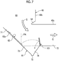
- Fig. 7 is a side view showing an exhaust duct of a second embodiment.
- the same reference numerals are assigned to the members having the same functions as those of the above-described embodiment, and detail descriptions thereof are omitted.
- the exhaust duct of the second embodiment includes the flue gas duct 60 through which the flue gas flows, the first hopper 61 which is provided in the flue gas duct 60 and in which solid particles in the flue gas are collected, the low-repulsion section 62 which is provided on the upstream side of the first hopper 61 in the direction of flow of the flue gas and has a lower coefficient of repulsion than that of the inner wall surface of the flue gas duct 60, and a popcorn-ash-trapping section (solid particle trapping section) 101 which is provided on the downstream sides of the first hopper 61 and the low-repulsion section 62 in the direction of flow of the flue gas and traps popcorn ashes in the flue gas.
- the first hopper 61 mainly collects and stores the PA which is ashes having large diameters included in the flue gas.
- the first hopper 61 includes the first inclination surface 73 and the second inclination surface 74 which face each other in the flow direction of the flue gas such that an area of the first hopper 61 decreases downward, and the storage section 75 is provided on a bottom position at which the lower end portions of the inclination surfaces 73 and 74 are connected to each other.
- the low-repulsion section 62 is provided on the lower wall surface section 71 in the first vertical flue gas duct section 40b on the upstream side of the first hopper 61 in the direction of flow of the flue gas.
- the low-repulsion section 62 has a sheet shape having a predetermined area, is fixed to the lower wall surface section (inclination surface) 71 in the first vertical flue gas duct section 40b, and is configured of a member having a lower coefficient of repulsion than that of the lower wall surface section 71 (for example, steel plate) to effectively improve trapping efficiency of the PA in the first hopper 61.
- the popcorn-ash-trapping section (solid particle trapping section) 101 traps the PA in the flue gas which cannot be collected by the first hopper 61.
- the popcorn-ash-trapping section 101 is formed of a wire netting having a mesh shape and is provided so as to be inclined in the vertical direction on the lower wall surface section (horizontal surface) 72. That is, the popcorn-ash-trapping section 101 is provided so as to be inclined by a predetermined angle such that the upper portion of the popcorn-ash-trapping section 101 is positioned on the upstream side (left side in Fig. 7 ) in the direction of flow of the flue gas G, and the trapping surface of the popcorn-ash-trapping section 101 faces the first hopper 61 side. Moreover, the popcorn-ash-trapping section 101 is provided at the height H1 of the region from 30% to 50% of the entire height H from the lower wall surface section (horizontal surface) to the second horizontal flue gas duct section 40c.
- the PA which collides with the lower end portion of the low-repulsion section 62 collides with the low-repulsion section 62, and the repulsion force of the PA decreases.
- the PA is scattered toward the first hopper 61 side.
- the PA which collides with the low-repulsion section 62 and jumps over the first hopper 61 collides with the popcorn-ash-trapping section 101, the PA is trapped by the popcorn-ash-trapping section 101 or falls so as to be collected in the first hopper 61.
- the low-repulsion section 62 which is provided on the upstream side of the first hopper 61 and the popcorn-ash-trapping section 101 which is provided on the downstream sides of the first hopper 61 and the low-repulsion section 62 are provided, and the popcorn-ash-trapping section 101 is provided so as to be inclined such that the upper portion is positioned on the upstream side in the direction of flow of the flue gas.
- the popcorn-ash-trapping section 101 since the popcorn-ash-trapping section 101 is provided so as to be inclined on the upstream side, the popcorn-ash-trapping section 101 causes the PA which is not collected in the first hopper 61 and flows to the downstream side to effectively fall into the first hopper 61 to trap the PA. As a result, it is possible to appropriately trap the PA in the flue gas G in the first hopper 61 and it is possible to improve trapping efficiency.
- Fig. 8 is a side view showing an exhaust duct of a third embodiment.
- the same reference numerals are assigned to the members having the same functions as those of the above-described embodiments, and detail descriptions thereof are omitted.
- the exhaust duct of the third embodiment includes the flue gas duct 60 through which the flue gas flows, the first hopper 61 which is provided in the flue gas duct 60 and in which solid particles in the flue gas are collected, the low-repulsion section 102 which is provided on the upstream side of the first hopper 61 in the direction of flow of the flue gas and has a lower coefficient of repulsion than that of the inner wall surface of the flue gas duct 60, and the popcorn-ash-trapping section 63 which is provided on the downstream sides of the first hopper 61 and the low-repulsion section 102 in the direction of flow of the flue gas and traps popcorn ashes in the flue gas.
- the first hopper 61 mainly collects and stores the PA which is ashes having large diameters included in the flue gas.
- the first hopper 61 includes the first inclination surface 73 and the second inclination surface 74 which face each other in the flow direction of the flue gas such that an area of the first hopper 61 decreases downward, and the storage section 75 is provided on a bottom position at which the lower end portions of the inclination surfaces 73 and 74 are connected to each other.
- the low-repulsion section 102 is provided from the lower wall surface section 71 to the first inclination surface 73 of the first hopper 61 in the first vertical flue gas duct section 40b on the upstream side of the first hopper 61 in the direction of flow of the flue gas.
- the low-repulsion section 102 has a sheet shape having a predetermined area, and is configured of a first low-repulsion section 103 which is fixed to the lower wall surface section (inclination surface) 71 in the first vertical flue gas duct section 40b, and a second low-repulsion section 104 which is fixed to the first inclination surface 73 of the first hopper 61.
- the low-repulsion section 102 is configured of a member having a lower coefficient of repulsion than that of the lower wall surface section 71 (for example, steel plate) to effectively improve trapping efficiency of the PA in the first hopper 61.
- the popcorn-ash-trapping section 63 traps the PA in the flue gas which cannot be collected by the first hopper 61.
- the popcorn-ash-trapping section 63 is formed of a wire netting having a mesh shape and is provided in the vertical direction on the lower wall surface section (horizontal surface) 72. Moreover, the popcorn-ash-trapping section 63 is provided at the height H1 of the region from 30% to 50% of the entire height H from the lower wall surface section (horizontal surface) to the second horizontal flue gas duct section 40c.
- the low-repulsion section 102 extends from the lower wall surface section (inclination surface) 71 to the first hopper 61, the repulsion force of the PA which directly falls into the first hopper 61 is decreased by the second low-repulsion section 104, and it is possible to prevent the PA from being scattered from the first hopper 61 again.
- the PA which collides with the lower end portion of the low-repulsion section 102 collides with the low-repulsion section 102, and the repulsion force of the PA decreases.
- the PA is scattered toward the first hopper 61 side.
- the PA which collides with the low-repulsion section 102 and jumps over the first hopper 61 collides with the popcorn-ash-trapping section 63, the PA is trapped by the popcorn-ash-trapping section 63 or falls so as to be collected in the first hopper 61.
- the low-repulsion section 102 which is provided on the upstream side of the first hopper 61 and the popcorn-ash-trapping section 63 which is provided on the downstream sides of the first hopper 61 and the low-repulsion section 102 are provided, and the inclination surface of the low-repulsion section 102 extends to the first inclination surface 73 of the first hopper 61.
- the PA is separated from the flue gas G and collected in the first hopper 61.
- the PA since the PA has an inertial force, the PA collides with the inner wall surface of the flue gas duct 60, is not collected in the first hopper 61, and easily flows to the downstream side.
- the PA collides with the first low-repulsion section 103 the repulsion amount of the PA decrease and the PA is appropriately collected in the first hopper 61.
- the repulsion force of the PA which directly falls into the first hopper 61 is decreased by the second low-repulsion section 104, and it is possible to prevent the PA from being scattered from the first hopper 61 again.
- the PA which is not collected in the first hopper 61 and flows to the downstream side is trapped by the popcorn-ash-trapping section 63.
- the PA which is not collected in the first hopper 61 and flows to the downstream side is trapped by the popcorn-ash-trapping section 63.
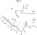
- Fig. 9 is a side view showing an exhaust duct of a fourth embodiment.
- the same reference numerals are assigned to the members having the same functions as those of the above-described embodiments, and detail descriptions thereof are omitted.
- the exhaust duct of the fourth embodiment includes the flue gas duct 60 through which the flue gas flows, the first hopper 61 which is provided in the flue gas duct 60 and in which solid particles in the flue gas are collected, a low-repulsion section 105 which is provided on the upstream side of the first hopper 61 in the direction of flow of the flue gas and has a lower coefficient of repulsion than that of the inner wall surface of the flue gas duct 60, and a popcorn-ash-trapping section 63 which is provided on the downstream sides of the first hopper 61 and the low-repulsion section 105 in the direction of flow of the flue gas and traps popcorn ashes in the flue gas.
- the flue gas duct 60 includes the first vertical flue gas duct section 40b through which the flue gas flows downward in the vertical direction and the second horizontal flue gas duct section 40c which is connected to the first vertical flue gas duct section 40b, and the first hopper 61 is provided below the connection section of the first vertical flue gas duct section 40b and the second horizontal flue gas duct section 40c.
- the lower wall surface section 71 is provided below the first vertical flue gas duct section 40b, and the lower wall surface section 71 is an inclination surface 71a which is inclined downward at a predetermined angle toward the first hopper 61 side and a horizontal surface 71b which is provided between the inclination surface 71a and the first hopper 61.
- the first hopper 61 mainly collects and stores the PA which is ashes having large diameters included in the flue gas.
- the first hopper 61 includes a first inclination surface 73 and a second inclination surface 74 which face each other in the flow direction of the flue gas such that an area of the first hopper 61 decreases downward, and the storage section 75 is provided on a bottom position at which the lower end portions of the inclination surfaces 73 and 74 are connected to each other.
- the low-repulsion section 105 is provided on the lower wall surface section 71 in the first vertical flue gas duct section 40b on the upstream side of the first hopper 61 in the direction of flow of the flue gas.
- the low-repulsion section 105 has a sheet shape having a predetermined area and is configured of a first low-repulsion section 106 which is fixed to the inclination surface 71a in the lower wall surface section 71 and a second low-repulsion section 107 which is fixed to the horizontal surface 71b in the lower wall surface section 71.
- the low-repulsion section 105 is configured of a member having a lower coefficient of repulsion than that of the lower wall surface section 71 (for example, steel plate) to effectively improve trapping efficiency of the PA in the first hopper 61.
- the popcorn-ash-trapping section 63 traps the PA in the flue gas which cannot be collected by the first hopper 61.
- the popcorn-ash-trapping section 63 is formed of a wire netting having a mesh shape and is provided so as to be inclined in the vertical direction on the lower wall surface section (horizontal surface) 72. Moreover, the popcorn-ash-trapping section 63 is provided at the height H1 of the region from 30% to 50% of the entire height H from the lower wall surface section (horizontal surface) to the second horizontal flue gas duct section 40c.
- the low-repulsion section 105 since the low-repulsion section 105 includes the first low-repulsion section 106 which becomes the inclination surface and the second low-repulsion section 107 which becomes the horizontal surface, the repulsion force of the PA, which falls on the first low-repulsion section 106 decreases, rolls on the first low-repulsion section 106 so as to be collected in the first hopper 61. In addition, the repulsion force of the PA which falls on the second low-repulsion section 107 decreases and the PA does not jump over the first hopper 61 and is collected in the first hopper 61. Moreover, the PA which collides with the lower end portion of the low-repulsion section 105 collides with the low-repulsion section 105, and the repulsion force of the PA decreases.
- the PA is scattered toward the first hopper 61 side.
- the PA which collides with the low-repulsion section 105 and jumps over the first hopper 61 collides with the popcorn-ash-trapping section 63, the PA is trapped by the popcorn-ash-trapping section 63 or falls so as to be collected in the first hopper 61.
- the low-repulsion section 105 which is provided on the upstream side of the first hopper 61 and the popcorn-ash-trapping section 63 which is provided on the downstream sides of the first hopper 61 and the low-repulsion section 105 are provided, and the low-repulsion section 105 extends from the inclination surface 71a of the lower wall surface section 71 to the horizontal surface 71b.
- the PA when the flue gas G flows through the flue gas duct 60, the PA is separated from the flue gas G and collected in the first hopper 61.
- the PA since the PA has the inertial force, the PA collides with the inner wall surface of the flue gas duct 60, is not collected in the first hopper 61, and easily flows to the downstream side.
- the PA collides with the inclined first low-repulsion section 106, the repulsion amount of the PA decrease and the PA appropriately rolls so as to be collected in the first hopper 61.
- the low-repulsion section 105 is provided from the inclination surface 71a of the lower wall surface section 71 to the horizontal surface 71b, the low-repulsion section 105 is formed to extend in the direction of flow of the flue gas and the horizontal second low-repulsion section 107 by which the inertial force of the PA can be decreased is formed. Therefore, the PA easily enters the first hopper 61 and it is possible to prevent the PA from being scattered from the first hopper 61 again. As a result, it is possible to appropriately trap the PA in the flue gas G in the first hopper 61 and it is possible to improve trapping efficiency.
- Fig. 10 is a side view showing an exhaust duct of a fifth embodiment.
- the same reference numerals are assigned to the members having the same functions as those of the above-described embodiments, and detail descriptions thereof are omitted.
- the exhaust duct of the fifth embodiment includes the flue gas duct 60 through which the flue gas flows, a second hopper 65 which is provided in the flue gas duct 60 and in which solid particles in the flue gas are collected, a low-repulsion section 111 which is provided on the upstream side of the second hopper 65 in the direction of flow of the flue gas and has a lower coefficient of repulsion than that of the inner wall surface of the flue gas duct 60, and a popcorn-ash-trapping section (solid particle trapping section) 112 which is provided on the downstream sides of the second hopper 65 and the low-repulsion section 111 in the direction of flow of the flue gas and traps popcorn ashes in the flue gas.
- the flue gas duct 60 includes the second horizontal flue gas duct section 40c through which the flue gas flows in the horizontal direction and the second vertical flue gas duct section 40d which is connected to the second horizontal flue gas duct section 40b and through which the flue gas flows upward in the vertical direction, and the second hopper 65 is provided below the connection section of the second horizontal flue gas duct section 40c and the second vertical flue gas duct section 40d.
- the lower wall surface section 72 is provided below the second horizontal flue gas duct section 40c, and the lower wall surface section 72 becomes a horizontal surface in the horizontal direction.
- a standing wall surface section 78 is provided at a position orthogonal to the lower wall surface section 72 on the downstream side (upper side in the vertical direction in Fig. 10 ) of the second hopper 65 in the direction of flow of the flue gas, and the standing wall surface section 78 become the vertical surface.
- the second hopper 65 mainly collects and stores the PA which is ashes having large diameters included in the flue gas.
- the second hopper 65 includes a first inclination surface 121 and a second inclination surface 122 which face each other in the flow direction of the flue gas such that an area of the second hopper 65 decreases downward, and a storage section 123 is provided on a bottom position at which the lower end portions of the inclination surfaces 121 and 122 are connected to each other.
- an opening portion which can be opened and closed by an on-off valve (not shown) is provided in the storage section 123, and the stored PA can be discharged downward by opening the opening portion.
- the lower wall surface section 72 of the second horizontal-vertical flue gas duct section 40c and the first inclination surface 121 of the second hopper 65 are connected to each other, and the standing wall surface section 78 of the second vertical flue gas duct section 40d and the second inclination surface 122 of the second hopper 65 are connected to each other.
- the low-repulsion section 111 is provided on the standing wall surface section 78 in the second vertical flue gas duct section 40d on the downstream side of the second hopper 65 in the direction of flow of the flue gas. Since the standing wall surface section 78 of the second vertical flue gas duct section 40d is the vertical surface, the surface of the low-repulsion section 111 becomes a vertical surface 111a.
- the low-repulsion section 111 has a sheet shape having a predetermined area and is configured of a member having a lower coefficient of repulsion than that of the standing wall surface section 78 (for example, steel plate) to effectively improve trapping efficiency of the PA in the second hopper 65.
- the repulsion amount of the PA decreases.
- the repulsion amount is smaller than the repulsion amount when the PA directly collides with the standing wall surface section 78 which is a steel plate, and the trapping efficiency of the PA in the second hopper 65 is improved.
- the popcorn-ash-trapping section 112 traps the PA in the flue gas which collides with the low-repulsion section 111.
- the second vertical flue gas duct section 40d has a rectangular cross section and includes the standing wall surface section 78, and the popcorn-ash-trapping section 112 is provided on the standing wall surface section 78 in the horizontal direction.
- the popcorn-ash-trapping section 112 is provided on a length L1 of a region from 30% to 50% of the entire length L from the standing wall surface section 78.
- the second horizontal flue gas duct section 40c and the second vertical flue gas duct section 40d are connected to each other so as to be bent 90°, the upstream end portion of the second vertical flue gas duct section 40d, that is, the outer peripheral side of the region immediately before the second hopper 65 is blocked by the popcorn-ash-trapping section 112.
- the PA which collides with the upper end portion of the low-repulsion section 111 collides with the low-repulsion section 111 and the repulsion force of the PA decreases.
- the PA may be scattered upward.
- the popcorn-ash-trapping section 112 is provided at the inlet portion of the second vertical flue gas duct section 40d, the PA which collides with the low-repulsion section 111 and is scattered collides with the popcorn-ash-trapping section 112. Accordingly, the PA is trapped by the popcorn-ash-trapping section 112 or falls so as to be collected in the second hopper 65.
- the flue gas duct 60 through which the flue gas flows the second hopper 65 which is provided in the flue gas duct 60 and in which the PA in the flue gas is collected, the low-repulsion section 111 which is provided on the downstream side of the second hopper 65 in the direction of flow of the flue gas and has a lower coefficient of repulsion than that of the inner wall surface of the flue gas duct 60, and the popcorn-ash-trapping section 112 which is provided on the downstream sides of the second hopper 65 and the low-repulsion section 111 in the direction of flow of the flue gas and traps the PA in the flue gas are provided.
- the PA is separated from the flue gas G and collected in the second hopper 65.
- the PA since the PA has an inertial force, the PA collides with the inner wall surface of the flue gas duct 60, is not collected in the second hopper 65, and is easily scattered to the surrounding.
- the PA collides with the low-repulsion section 111, the repulsion amount of the PA decrease and the PA is appropriately collected in the second hopper 65.
- a portion of the PA which collides with the low-repulsion section 111 and is scattered to the surrounding is trapped by the popcorn-ash-trapping section 112. As a result, it is possible to appropriately trap the PA in the flue gas G in the second hopper 65 and it is possible to improve trapping efficiency.
- the popcorn-ash-trapping sections 63, 101, and 112 are provided in the region from 30% to 50% of the height H or the length L of the flue gas duct 60.
- the popcorn-ash-trapping sections 63, 101, and 112 may be provided in a region of 100% of the height H or the length L of the flue gas duct 60. In this case, it is possible to reliably trap the PA which is not collected in the hoppers 61 and 65 and flows toward the downstream side by the popcorn-ash-trapping section.
- the present invention is not limited this type of boiler.
- the present invention is not limited to the boiler, and the present invention may be applied to any exhaust duct as long as the flue gas including the solid particles can flow to it.
Landscapes
- Engineering & Computer Science (AREA)
- Mechanical Engineering (AREA)
- General Engineering & Computer Science (AREA)
- Chemical & Material Sciences (AREA)
- Chemical Kinetics & Catalysis (AREA)
- Combustion & Propulsion (AREA)
- Incineration Of Waste (AREA)
- Separating Particles In Gases By Inertia (AREA)
Abstract
Description
- The present invention relates to an exhaust duct which is applied to a boiler which generates steam for power generation, a factory, or the like, and a boiler including the exhaust duct.
- For example, in the related art, a pulverized coal fired boiler includes a furnace which has a hollow shape and is installed in a vertical direction, and a plurality of combustion burners are disposed on a wall of the furnace along a circumferential direction and are arranged in a plurality of stages in an upward-downward direction. A gaseous mixture of pulverized coal (fuel) which is crushed coal and transport air (primary air) is supplied to the combustion burner, high-temperature secondary air is supplied to the combustion burner, flames are generated by blowing the gaseous mixture and the secondary gas into the furnace, and combustion gas can be generated in the furnace. In addition, a flue gas duct is connected to the upper portion of the furnace, a superheater, a reheater, an economizer, or the like for collecting heat of a flue gas is provided in the flue gas duct, water is heated by an exhaust gas generated by combustion in the furnace, and steam can be generated. In addition, a flue gas duct is connected to the flue gas duct, a denitration device, an electric dust collector, a desulfurization device, or the like is provided in the flue gas duct, and a funnel is provided on a downstream end portion of the flue gas duct.
- For example, as the boiler, there are boilers which are disclosed in PTLs below.
-
- [PTL 1] Specification of
US Patent 6994036 - [PTL 2] Japanese Unexamined Patent Application Publication No.
2013-103214 - In the above-described pulverized coal fired boiler, since pulverized coal which is a fuel is combusted in a furnace, popcorn ashes (massive ashes) which solid particles may be mixed into the flue gas. Since the popcorn ashes are lumps of ashes, particularly, the popcorn ashes block a screen, a denitration device, or the like provided in a flue gas duct. Accordingly, the screen is abraded and needs so as to be exchanged, and a maintenance cost increases. In addition, the popcorn ashes are accumulated on the screen or the denitration device, pressure loss increases, and performance decreases. Moreover, in a flue gas treatment device of PTL 2, a popcorn-ash-trapping section is provided on the downstream side of a hopper. However, there is a concern that the popcorn-ash-trapping section may be damaged by collision of the popcorn ashes due to a long-term use.
- The present invention is made to solve the above-described problems, and an object thereof is to provide an exhaust duct and a boiler in which solid particles in a flue gas can be appropriately trapped.
- In order to achieve the object, according to an aspect of the present invention, there is provided an exhaust duct, including: a flue gas duct through which a flue gas flows; a hopper which is provided in the flue gas duct and collects solid particles in the flue gas; a low-repulsion section which is provided on an upstream side or a downstream side of the hopper in a direction of flow of the flue gas and has a lower coefficient of repulsion than that of an inner wall surface of the flue gas duct; and a solid particle trapping section which is provided on downstream sides of the hopper and the low-repulsion section in the direction of flow of the flue gas and traps solid particles in the flue gas.
- Accordingly, when the flue gas flows through the flue gas duct, the solid particles are separated from the flue gas and collected in the hopper. In this case, since the solid particles have an inertial force, the solid particles collide with the inner wall surface of the flue gas duct, are not collected in the hopper, and easily flow to the downstream side. However, since the solid particles collide with the low-repulsion section, repulsion amounts of the solid particles decrease and the solid particles are appropriately collected in the hopper. In addition, the solid particles which are not collected in the hopper and flow to the downstream side are trapped by the solid particle trapping section. As a result, it is possible to appropriately trap the solid particles in the flue gas in the hopper and it is possible to improve trapping efficiency.
- In the exhaust duct of the present invention, the flue gas duct includes a first vertical section through which the flue gas flows downward in a vertical direction and a horizontal section which is connected to the first vertical section, the hopper is provided below a connection section between the first vertical section and the horizontal section, and the low-repulsion section is provided on the lower wall surface section in the first vertical section on the upstream side of the hopper in the direction of flow of the flue gas.
- Accordingly, if the low-repulsion section is provided on the upstream side of the hopper, the solid particles included in the flue gas collide with the low-repulsion section before the hopper, the inertial force of the solid particles decreases, and the solid particles easily enter the hopper. Accordingly, it is possible to decrease the amount of the solid particles which jump over the hopper and are scattered toward the downstream side to flow out.
- In the exhaust duct of the present invention, the low-repulsion section includes an inclination surface which is inclined in the same direction as that of an inclination surface of the hopper.
- Accordingly, since the inclination surface of the low-repulsion section and the inclination surface of the hopper are inclined in the same direction, if the solid particles included in the flue gas collide with the low-repulsion section, the solid particles fall along the inclination surface of the hopper from the inclination surface of the low-repulsion section so as to be collected in the hopper, and it is possible to appropriately introduce the solid particles to the hopper.
- In the exhaust duct of the present invention, the inclination surface of the low-repulsion section extends to the inclination surface of the hopper.
- Accordingly, since the low-repulsion section extends to the hopper, the inertial force of the solid particles is appropriately decreased by the low-repulsion section so as to easily enter the hopper, and it is possible to prevent the solid particles from being scattered from the hopper again.
- In the exhaust duct of the present invention, the lower wall surface section of the first vertical section includes an inclination surface and a horizontal surface arranged in the direction of flow of the flue gas, and the low-repulsion section is provided from the inclination surface to the horizontal surface.
- Accordingly, since the low-repulsion section is provided from the inclination surface to the horizontal surface, the low-repulsion section is formed to extend in the direction of flow of the flue gas and the horizontal surface by which the inertial force of the solid particles can be decreased is formed. Therefore, the solid particles easily enter the hopper and it is possible to prevent the solid particles from being scattered from the hopper again.
- In the exhaust duct of the present invention, the solid particle trapping section is provided in the vertical direction.
- Accordingly, since the solid particles which are not collected in the hopper and flow to the downstream side collide with the solid particle trapping section, it is possible to appropriately trap the solid particles.
- In the exhaust duct of the present invention, the solid particle trapping section is provided so as to be inclined such that the upper portion is positioned on the upstream side in the direction of flow of the flue gas.
- Accordingly, since the solid particle trapping section is provided so as to be inclined on the upstream side, the solid particle trapping section causes the solid particles which are not collected in the hopper and flow to the downstream side to effectively fall into the hopper to trap the solid particles.
- In the exhaust duct of the present invention, the solid particle trapping section is provided in a region of 30% to 50% of the entire height of the flue gas duct from the lower wall surface section in the horizontal section.
- Accordingly, since the solid particle trapping section is provided in only the region to which the solid particles which are not collected in the hopper easily flow out, it is possible to reduce the size and the cost of the solid particle trapping section.
- In the exhaust duct of the present invention, the solid particle trapping section is provided in a region of 100% of the entire height of the flue gas duct.
- Accordingly, since the solid particle trapping section is provided on the entire region of the exhaust duct, it is possible to more reliably trap the solid particles, which are not collected in the hopper and flow to the downstream side, by the solid particle trapping section.
- In the exhaust duct of the present invention, the flue gas duct includes a horizontal section through which the flue gas flows in a horizontal direction and a second vertical section which is connected to the horizontal section and through which the flue gas flows upward in a vertical direction, the hopper is provided below a connection section between the horizontal section and the second vertical section, and the low-repulsion section is provided on a standing wall surface section in the second vertical section facing the horizontal section on the downstream side of the hopper in the direction of flow of the flue gas.
- Accordingly, if the low-repulsion section is provided on the downstream side of the hopper, since the solid particles included in the flue gas passes through the upper portion of the hopper and thereafter, collide with the low-repulsion section, the inertial force of the solid particles decreases and the solid particles easily enter the hopper. Therefore, it is possible to decrease the amounts of the solid particles which jump over the hopper and are scattered toward the downstream side so as to flow out.
- In the exhaust duct of the present invention, the solid particle trapping section is provided in the horizontal direction.
- Accordingly, since the solid particles which are not collected in the hopper and flow to the downstream side collide with the solid particle trapping section, it is possible to appropriately trap the solid particles.
- In the exhaust duct of the present invention, the solid particle trapping section is provided in a region of 30% to 50% of a horizontal length of the second vertical section from the standing wall surface section in the second vertical section facing the horizontal section.
- Accordingly, since the solid particle trapping section is provided in only the region to which the solid particles which are not collected in the hopper easily flow out, it is possible to reduce the size and the cost of the solid particle trapping section.
- In addition, according to another aspect of the present invention, there is provided a boiler including: a furnace which has a hollow shape and is installed in a vertical direction; combustion equipment which blows a fuel toward the inner portion of the furnace and combusts the fuel; the exhaust duct which is connected to a downstream side in a direction of flow of a flue gas in the furnace; and a heat collection section which is provided in the exhaust duct and can collect heat in the flue gas.
- Accordingly, flames are generated by blowing the fuel into the furnace using the combustion equipment, the generated combustion gas flows into the exhaust duct, and the solid particles are separated from the flue gas and collected in the hopper while the heat collection section collects the heat of the flue gas. In this case, in the flue gas which flows through the flue gas duct, since the solid particles are separated from the flue gas and collide with the low-repulsion section, the repulsion amounts of the solid particles decrease, and the solid particles are appropriately collected in the hopper. Accordingly, the solid particles which are not collected in the hopper and flow to the downstream side are trapped by the solid particle trapping section. As a result, it is possible to appropriately trap the solid particles of the flue gas in the hopper, and it is possible to improve trapping efficiency.
- According to the exhaust duct and the boiler of the present invention, since the low-repulsion section having a lower coefficient of repulsion than that of an inner wall surface of the flue gas duct is provided on the upstream side or the downstream side of the hopper and the solid particle trapping section is provided on the downstream sides of the hopper and the low-repulsion section, it is possible to appropriately trap the solid particles of the flue gas in the hopper and it is possible to improve trapping efficiency.
-
-
Fig. 1 is a side view showing an exhaust duct of a first embodiment. -
Fig. 2 is a sectional view taken along line II-II ofFig. 1 showing the exhaust duct. -
Fig. 3 is a perspective view showing a low-repulsion structure section which is provided in the exhaust duct. -
Fig. 4 is a schematic view showing effects of the low-repulsion structure section. -
Fig. 5 is a schematic view showing effects of the low-repulsion structure section. -
Fig. 6 is a schematic configuration view showing a pulverized coal fired boiler to which the exhaust duct of the first embodiment is applied. -
Fig. 7 is a side view showing an exhaust duct of a second embodiment. -
Fig. 8 is a side view showing an exhaust duct of a third embodiment. -
Fig. 9 is a side view showing an exhaust duct of a fourth embodiment. -
Fig. 10 is a side view showing an exhaust duct of a fifth embodiment. - Hereinafter, preferred embodiments of an exhaust duct and a boiler of the present invention will be described in detail with reference to the accompanying drawings. In addition, the present invention is not limited by the embodiments, and in a case where there are the plurality of embodiments, the present invention also includes combination of the embodiments.
-
Fig. 6 is a schematic configuration view showing a pulverized coal fired boiler to which an exhaust duct of a first embodiment is applied. - The pulverized coal fired boiler to which the exhaust duct of the first embodiment is applied is a boiler in which pulverized coal which is crushed coal is used as a solid fuel, the pulverized coal is combusted by a combustion burner, and heat generated by the combustion can be collected. In addition, here, the case where the pulverized coal fired boiler is applied is described. However, in the present invention, the boiler is not limited to the pulverized coal fired boiler, and the fuel is not limited to the coal.
- In the first embodiment, as shown in
Fig. 6 , a pulverized coal firedboiler 10 is a conventional boiler, and includes afurnace 11 and combustion equipment 12. Thefurnace 11 has a square cylindrical hollow shape and is installed along a vertical direction, and the combustion equipment 12 is provided on a lower portion of a furnace wall configuring thefurnace 11. - The combustion equipment 12 includes a plurality of
combustion burners combustion burners - In addition, each of the
combustion burners coal supply pipes coal pulverizers coal supply pipes combustion burners - Moreover, in the
furnace 11, awind box 36 is provided on the mounting position of each of thecombustion burners air duct 37 is connected to thewind box 36, and ablower 38 is mounted on the other end portion of theair duct 37. Accordingly, combustion air (secondary air and tertiary air) fed by theblower 38 is supplied from theair duct 37 to thewind box 36, and the combustion air can be supplied from thewind box 36 to each of thecombustion burners - Therefore, in the combustion equipment 12, each of the
combustion burners furnace 11, can blow the secondary air into thefurnace 11, and can form flames by igniting the pulverized fuel-gas mixture using an ignition torch (not shown). - Moreover, in general, when the boiler starts, each of the
combustion burners furnace 11. - A
flue gas duct 40 is connected to the upper portion offurnace 11, and superheaters 41 and 42 for collecting the heat of the flue gas, reheaters 43 and 44, andeconomizers flue gas duct 40, and heat exchange is performed between the flue gas generated by the combustion of thefurnace 11 and water. - A flue gas pipe (flue gas duct) 48 through which the flue gas subjected to the heat exchange is discharged is connected to the downstream side of the
flue gas duct 40. Anair heater 49 is provided between theflue gas pipe 48 and theair duct 37, heat exchange between air flowing through theair duct 37 and the flue gas flowing through theflue gas pipe 48 is performed, and it is possible to increase temperature of the combustion air supplied to thecombustion burners - In addition, in the
flue gas pipe 48, a selectivereduction type catalyst 50 is provided at the position on the upstream side of theair heater 49, an ash dust processing device (electric dust collector, desulfurization device) 51 and an inducedblower 52 are provided at the position on the downstream side of theair heater 49, and afunnel 53 is provided on the downstream end portion of theflue gas pipe 48. Here, the selectivereduction type catalyst 50 and the electric ashdust processing device 51 function as a harmful matter removing portion. - Accordingly, if the
coal pulverizers combustion burners coal supply pipes air duct 37 to each of thecombustion burners wind box 36. Accordingly, thecombustion burners furnace 11 and blow the combustion air into thefurnace 11, and at this time, it is possible to form flames by performing ignition. In thefurnace 11, the pulverized fuel-gas mixture and the combustion air are combusted, flames are generated, and if flames are generated at the lower portion inside thefurnace 11, the combustion gas (flue gas) rises in thefurnace 11 and is discharged to theflue gas duct 40. - In addition, in the
furnace 11, since a supply amount of air is set so as to be less than a theoretical air amount with respect to a supply amount of the pulverized coal, a reduction atmosphere is maintained in the inner portion of thefurnace 11. In addition, NOx generated by the combustion of the pulverized coal is reduced in thefurnace 11, and thereafter, oxidation combustion of the pulverized coal is completed by additionally supplying additional air, and the generation amount of NOx is decreased by the combustion of the pulverized coal. - At this time, after water supplied from a water supply pump (not shown) is preheated by the
economizers superheaters reheaters type furnace 11 is described. However, the present invention is not limited to this structure. - Thereafter, harmful materials such as NOx of the flue gas passing through the
economizers flue gas duct 40 are removed by the selectivereduction type catalyst 50 in theflue gas pipe 48, particle materials and the sulfur contents are removed by the ashdust processing device 51, and thereafter, the flue gas is discharged from thefunnel 53 to the atmosphere. - In the pulverized coal fired
boiler 10 described as above, theflue gas duct 40 on the downstream side of thefurnace 11 functions as the exhaust duct of the first embodiment. In addition, in theflue gas duct 40, a first horizontal flue gas duct section (first vertical section) 40a, a first vertical fluegas duct section 40b, a second horizontal flue gas duct section (horizontal section) 40c, a second vertical flue gas duct section (second vertical section) 40d, a third horizontal fluegas duct section 40e, a third vertical fluegas duct section 40f, and a fourth horizontal fluegas duct section 40g are continuously provided. In addition, akicker 54 is provided on the inner side of a connection section between the first vertical fluegas duct section 40b and the second horizontal fluegas duct section 40c in the horizontal direction. - In addition, in the
flue gas duct 40, thesuperheaters reheaters economizers gas duct section 40a and the first vertical fluegas duct section 40b. In addition, in theflue gas duct 40, afirst hopper 61 is installed on the lower end portion of the first vertical fluegas duct section 40b through which the flue gas having a downward velocity component flows, and asecond hopper 65 is installed on the lower end portion of the second vertical fluegas duct section 40d through which the flue gas having an upward velocity component flows. In addition, in theflue gas duct 40, the selectivereduction type catalyst 50 is installed in the third vertical fluegas duct section 40f through which the flue gas flows downward. - Hereinafter, the exhaust duct of the first embodiment will be described in detail.
Fig. 1 is a side view showing the exhaust duct of the first embodiment, andFig. 2 is a sectional view taken along line II-II ofFig. 1 showing the exhaust duct. - As shown in
Figs. 1 and 2 , the exhaust duct of the first embodiment includes aflue gas duct 60 through which a flue gas flows, thefirst hopper 61 which is provided in theflue gas duct 60 and in which solid particles in the flue gas are collected, a low-repulsion section 62 which is provided on the upstream side of thefirst hopper 61 in the direction of flow of the flue gas and has a lower coefficient of repulsion than that of the inner wall surface of theflue gas duct 60, and a popcorn-ash-trapping section (solid particle trapping section) 63 which is provided on the downstream sides of thefirst hopper 61 and the low-repulsion section 62 in the direction of flow of the flue gas and traps popcorn ashes (solid particles and hereinafter, referred to as PA) in the flue gas. - The
flue gas duct 60 includes a first vertical fluegas duct section 40b through which the flue gas duct gas flows downward in the vertical direction and the second horizontal fluegas duct section 40c which is connected to the first vertical fluegas duct section 40b and through which the flue gas flows in the horizontal direction, and thefirst hopper 61 is provided below the connection section of the first vertical fluegas duct section 40b and the second horizontal fluegas duct section 40c. A lowerwall surface section 71 is provided below the first vertical fluegas duct section 40b, and the lowerwall surface section 71 is an inclination surface which is inclined downward at a predetermined angle toward the second horizontal fluegas duct section 40c side and thefirst hopper 61 side. A lowerwall surface section 72 is provided below the second horizontal fluegas duct section 40c, and the lowerwall surface section 72 is a horizontal surface positioned in the horizontal direction. - The
first hopper 61 mainly collects and stores the PA which is ashes having large diameters as the solid particles included in the flue gas. Thefirst hopper 61 includes afirst inclination surface 73 and asecond inclination surface 74 which face each other in the flow direction of the flue gas such that an area of thefirst hopper 61 decreases downward, and astorage section 75 is provided on a bottom position at which the lower end portions of the inclination surfaces 73 and 74 are connected to each other. In addition, in thefirst hopper 61, an opening portion which can be opened and closed by an on-off valve (not shown) is provided in thestorage section 75, and the stored PA can be discharged downward by opening the opening portion. - Here, the lower
wall surface section 71 of the first vertical fluegas duct section 40b and thefirst inclination surface 73 of thefirst hopper 61 are connected to each other so as to be surfaces which are continued at approximately the same inclination angle. The angles of the lowerwall surface section 71 and thefirst inclination surface 73 are set so as to be equal to or more than a repose angle such that the PA is dropped. In addition, thesecond inclination surface 74 of thefirst hopper 61 and the second horizontal fluegas duct section 40c are connected so as to be bent at a predetermined angle. - The low-
repulsion section 62 is provided on the lowerwall surface section 71 in the first vertical fluegas duct section 40b on the upstream side of thefirst hopper 61 in the direction of flow of the flue gas. Since the lowerwall surface section 71 of the first vertical fluegas duct section 40b is an inclination surface, the surface of the low-repulsion section 62 becomes aninclination surface 62a and has approximately the same angle as that of thefirst inclination surface 73. The low-repulsion section 62 has a sheet shape having a predetermined area, is fixed to the lower wall surface section (inclination surface) 71 in the first vertical fluegas duct section 40b, and is configured of a member having a lower coefficient of repulsion than that of the lower wall surface section 71 (for example, steel plate) to effectively improve trapping efficiency of the PA in thefirst hopper 61. Accordingly, when the PA falls along the low-repulsion section 62, since the PA falls while coming into contact with theinclination surface 62a, the repulsion amount of the PA is decreased when the PA collides with the low-repulsion section 62. - As a result, since the PA which falls along with the downward flue gas G directly collides with the low-
repulsion section 62, the PA is repulsed so as to be smaller than the repulsion amount of the PA when the PA directly collides with the lowerwall surface section 71 which is a steel plate, a probability of the PA jumping over thefirst hopper 61 and being scattered toward the lowerwall surface section 72 of the second horizontal fluegas duct section 40c is reduced, and the trapping efficiency of the PA in thefirst hopper 61 is improved. - Hereinafter, a specific configuration example of the above-described low-
repulsion section 62 will be described.Fig. 3 is a perspective view showing the low-repulsion structure section which is provided in the exhaust duct, andFigs. 4 and5 are schematic views showing effects of the low-repulsion structure section. - As shown in
Fig. 3 , the low-repulsion section 62 includes a wire netting (low-repulsion section formation member) 81 and a pair offrame bodies 82 which supports the wire netting 81 from both sides. Since thewire netting 81 is disposed so as to float by a predetermined height with respect to the lower wall surface section (inclination surface) 71 of a steel-plate duct by the pair offrame bodies 82, aspace section 83 is formed between the lower wall surface section (inclination surface) 71 and the wire netting. In addition, a plurality of openingportions 84 serving as the passage of the PA are provided in thewire netting 81. Accordingly, as shown inFig. 4 , the PA which falls downward in the vertical direction passes through the openingportions 84 of thewire netting 81 and collides with the lower wall surface section (inclination surface) 71 so as to be repulsed. However, thereafter, the PA is likely to collide with the back face side of the wire netting 81 again. As a result, the PA which collides with the back face side of the wire netting 81 falls into thespace section 83 along the lower wall surface section (inclination surface) 71, and finally is collected in thefirst hopper 61. - Meanwhile, all PA which falls downward in the vertical direction does not pass through the opening
portions 84 of thewire netting 81, and the PA may collide with the wire netting 81 in which linear members are combined in a lattice shape. As shown inFig. 5 , the PA which collides with the linear members of thewire netting 81 collides with a member which has a lower coefficient of repulsion than that of a general steel plate and is easily elastic-deformed, and as a result, the repulsion amount of the PA decreases, and the PA is likely to be collected in thefirst hopper 61. In this way, in the low-repulsion section 62, since the PA which passes through the openingportions 84 of thewire netting 81 and collides with the wire netting 81 can be effectively collected in thefirst hopper 61, it is possible to improve trapping efficiency of the PA in thefirst hopper 61. - In addition, the low-
repulsion section 62 iswire netting 81. However the low-repulsion section 62 is not limited to this. As the low-repulsion section, in addition to thewire netting 81, for example, a lattice-shaped member such as a grating, a porous plate, or a bamboo blind structure (slatted shutter) may be used, which includes a plurality of opening portions having sizes in which the PA can pass through. Particularly, like the linear member of thewire netting 81, if the lattice-shaped low-repulsion member formed of a material which collides with the PA and is elastically deformed is adopted, collision energy of the PA due to elastic deformation is effectively absorbed, and it is possible to decrease the repulsion amount. In addition, due to rotation of the collided PA, the repulsion amount can be decreased. In addition, the low-repulsion section 62 is not limited to the porous member, and as the low-repulsion section 62, a heat insulation material, a rubber material, a plastic material, or the like which is not porous may be adopted. - In addition, as shown in
Figs. 1 and 2 , the popcorn-ash-trappingsection 63 traps the PA in the flue gas which cannot be collected by thefirst hopper 61. The popcorn-ash-trappingsection 63 is formed of a wire netting having a mesh shape, and for example, is configured of a plurality of openings in which one side is set to 2 mm to 3 mm or less. In addition, the popcorn-ash-trappingsection 63 is not limited to the wire netting having a mesh shape, and may be a screen or a porous body having vertical slits or horizontal slits. - The second horizontal flue
gas duct section 40c has a rectangular cross section, and is configured such that side wall surface portions (vertical surfaces) 76 are formed on both sides of the lower wall surface section (horizontal surface) 72 and an upper wall surface portion (horizontal surface) 77 is formed on each sidewall surface portion 76. The popcorn-ash-trappingsection 63 is provided on the lower wall surface section (horizontal surface) 72 in the vertical direction. Moreover, the popcorn-ash-trappingsection 63 is provided at a height H1 of a region from 30% to 50% of the entire height H from the lower wall surface section (horizontal surface) to the second horizontal fluegas duct section 40c. In this case, the popcorn-ash-trappingsection 63 is provided on a region from 30% to 50% in a passage area of theflue gas duct 60. That is, the first vertical fluegas duct section 40b and the second horizontal fluegas duct section 40c are connected to each other so as to be bent 90°, the upstream end portion of the second horizontal fluegas duct section 40c, that is, the outer peripheral side of the region immediately after thefirst hopper 61 is blocked by the popcorn-ash-trappingsection 63. - Here, effects of the exhaust duct of the first embodiment will be described.
- As shown in
Fig. 6 , after heat of flue gas G is collected by the heat collection section (superheaters economizers flue gas duct 40, the flue gas moves downward along the first vertical fluegas duct section 40b, is curved so as to be approximately perpendicular to the first vertical fluegas duct section 40b, and flows into the second horizontal fluegas duct section 40c. At this time, the PA included in the flue gas G freely falls so as to be stored in thefirst hopper 61. - When the flue gas G flows from the first vertical flue
gas duct section 40b into the second horizontal fluegas duct section 40c, kinetic energy is applied to the PA from the flue gas, and the PA1 falls on the lower wall surface section (inclination surface) 71 or thefirst hopper 61 side at a predetermined speed due to an inertial force (centrifugal force). In this case, the PA which falls downward collides with the low-repulsion section 62, a repulsion force of the PA1 decreases, and the PA rolls on the inclination surface of the low-repulsion section 62 so as to be collected in thefirst hopper 61. - In addition, the PA which collides with the lower end portion of the low-
repulsion section 62 collides with the low-repulsion section 62, and the repulsion force of the PA decreases. However, there is a concern that the PA may jump over thefirst hopper 61. However, since the popcorn-ash-trappingsection 63 is provided at the inlet portion of the second horizontal fluegas duct section 40c, the PA which collides with the low-repulsion section 62 and jumps over thefirst hopper 61 collides with the popcorn-ash-trappingsection 63. Accordingly, the PA is trapped by the popcorn-ash-trappingsection 63 or falls so as to be collected in thefirst hopper 61. - In this way, in the exhaust duct of the first embodiment, the
flue gas duct 60 through which the flue gas flows, thefirst hopper 61 which is provided in theflue gas duct 60 and in which the PA in the flue gas is collected, the low-repulsion section 62 which is provided on the upstream side of thefirst hopper 61 in the direction of flow of the flue gas and has a lower coefficient of repulsion than that of the inner wall surface of theflue gas duct 60, and the popcorn-ash-trappingsection 63 which is provided on the downstream sides of thefirst hopper 61 and the low-repulsion section 62 in the direction of flow of the flue gas and traps the PA in the flue gas are provided. - Accordingly, when the flue gas G flows through the
flue gas duct 60, the PA is separated from the flue gas G and collected in thefirst hopper 61. In this case, since the PA has the inertial force, the PA collides with the inner wall surface of theflue gas duct 60, is not collected in thefirst hopper 61, and easily flows to the downstream side. However, since the PA collides with the low-repulsion section 62, the repulsion amount of the PA decrease and the PA is appropriately collected in thefirst hopper 61. In addition, the PA which is not collected in thefirst hopper 61 and flows to the downstream side is trapped by the popcorn-ash-trappingsection 63. As a result, it is possible to appropriately trap the PA in the flue gas G in thefirst hopper 61 and it is possible to improve trapping efficiency. - In the exhaust duct of the first embodiment, the
flue gas duct 60 includes the first vertical fluegas duct section 40b through which the flue gas G flows downward in a vertical direction and the second horizontal fluegas duct section 40c which is connected to the first vertical fluegas duct section 40b, thefirst hopper 61 is provided below the connection section between the first vertical fluegas duct section 40b and the second horizontal fluegas duct section 40c, and the low-repulsion section 62 is provided on the lowerwall surface section 71 in the first vertical fluegas duct section 40b on the upstream side of thefirst hopper 61 in the direction of flow of the flue gas. Accordingly, if the low-repulsion section 62 is provided on the upstream side of thefirst hopper 61, the PA included in the flue gas G collides with the low-repulsion section 62 before thefirst hopper 61, the inertial force of the PA decreases, and the PA easily enters thefirst hopper 61. Accordingly, it is possible to decreases the amount of the PA which jumps over thefirst hopper 61 and is scattered toward the downstream side to flow out. - In the exhaust duct of the first embodiment, the low-
repulsion section 62 includes the inclination surface which is inclined in the same direction as that of thefirst inclination surface 73 of thefirst hopper 61. Accordingly, if the PA included in the flue gas G collides with the low-repulsion section 62, the PA falls along thefirst inclination surface 73 of thefirst hopper 61 from the inclination surface of the low-repulsion section 62 so as to be collected in thefirst hopper 61, and it is possible to appropriately introduce the PA to thefirst hopper 61. - In the exhaust duct of the first embodiment, the popcorn-ash-trapping
section 63 is provided on the lowerwall surface section 72 in the second horizontal fluegas duct section 40c in the vertical direction. Accordingly, since the PA which is not collected in thefirst hopper 61 and flows to the downstream side collides with the popcorn-ash-trappingsection 63, it is possible to appropriately trap the PA. - In the exhaust duct of the first embodiment, the popcorn-ash-trapping
section 63 is provided at the height H1 of the region of 30% to 50% of the entire height H from the lowerwall surface section 72 in the first horizontal fluegas duct section 40c. When the flue gas G flows from the first vertical fluegas duct section 40b into the second horizontal fluegas duct section 40c, the PA does not nearly flow to the upstream side of the second horizontal fluegas duct section 40c by the inertial force. Accordingly, since the popcorn-ash-trappingsection 63 is provided in only the region to which the PA which is not collected in thefirst hopper 61 easily flow out, it is possible to reduce the size and the cost of the popcorn-ash-trappingsection 63. In addition, since the popcorn-ash-trappingsection 63 is provided on only a portion of the second horizontal fluegas duct section 40c, even when the PA is attached to the popcorn-ash-trappingsection 63 and the popcorn-ash-trappingsection 63 is blocked, it is possible to decrease occurrence of erosion, and it is possible to prevent an increase in a pressure loss. - Moreover, in the boiler of the first embodiment, the
furnace 11 which has a hollow shape and is installed along the vertical direction, a combustion equipment 12 which blows the fuel gas toward the inner portion of thefurnace 11 and combusts the fuel gas, the exhaust duct which is connected to a downstream side in the direction of the flow of the flue gas in thefurnace 11, and the heat collection section (superheaters economizers - Accordingly, flames are formed by blowing the fuel gas into the
furnace 11 with the combustion equipment 12, the generated combustion gas flows into the exhaust duct, and the PA is separated from the flue gas G so as to be collected in thefirst hopper 61 while the heat in the flue gas is collected by the heat collection section. In this case, since the PA collides with the low-repulsion section 62, repulsion amount of the PA decreases and the PA is appropriately collected in thefirst hopper 61. In addition, the solid particles which are not collected in thefirst hopper 61 and flow to the downstream side are trapped by the popcorn-ash-trappingsection 63. As a result, it is possible to appropriately trap the PA in the flue gas G in thefirst hopper 61 and it is possible to improve trapping efficiency. -
Fig. 7 is a side view showing an exhaust duct of a second embodiment. In addition, the same reference numerals are assigned to the members having the same functions as those of the above-described embodiment, and detail descriptions thereof are omitted. - As shown in
Fig. 7 , the exhaust duct of the second embodiment includes theflue gas duct 60 through which the flue gas flows, thefirst hopper 61 which is provided in theflue gas duct 60 and in which solid particles in the flue gas are collected, the low-repulsion section 62 which is provided on the upstream side of thefirst hopper 61 in the direction of flow of the flue gas and has a lower coefficient of repulsion than that of the inner wall surface of theflue gas duct 60, and a popcorn-ash-trapping section (solid particle trapping section) 101 which is provided on the downstream sides of thefirst hopper 61 and the low-repulsion section 62 in the direction of flow of the flue gas and traps popcorn ashes in the flue gas. - The
first hopper 61 mainly collects and stores the PA which is ashes having large diameters included in the flue gas. Thefirst hopper 61 includes thefirst inclination surface 73 and thesecond inclination surface 74 which face each other in the flow direction of the flue gas such that an area of thefirst hopper 61 decreases downward, and thestorage section 75 is provided on a bottom position at which the lower end portions of the inclination surfaces 73 and 74 are connected to each other. The low-repulsion section 62 is provided on the lowerwall surface section 71 in the first vertical fluegas duct section 40b on the upstream side of thefirst hopper 61 in the direction of flow of the flue gas. The low-repulsion section 62 has a sheet shape having a predetermined area, is fixed to the lower wall surface section (inclination surface) 71 in the first vertical fluegas duct section 40b, and is configured of a member having a lower coefficient of repulsion than that of the lower wall surface section 71 (for example, steel plate) to effectively improve trapping efficiency of the PA in thefirst hopper 61. - The popcorn-ash-trapping section (solid particle trapping section) 101 traps the PA in the flue gas which cannot be collected by the
first hopper 61. The popcorn-ash-trappingsection 101 is formed of a wire netting having a mesh shape and is provided so as to be inclined in the vertical direction on the lower wall surface section (horizontal surface) 72. That is, the popcorn-ash-trappingsection 101 is provided so as to be inclined by a predetermined angle such that the upper portion of the popcorn-ash-trappingsection 101 is positioned on the upstream side (left side inFig. 7 ) in the direction of flow of the flue gas G, and the trapping surface of the popcorn-ash-trappingsection 101 faces thefirst hopper 61 side. Moreover, the popcorn-ash-trappingsection 101 is provided at the height H1 of the region from 30% to 50% of the entire height H from the lower wall surface section (horizontal surface) to the second horizontal fluegas duct section 40c. - Accordingly, when the flue gas G flows from the first vertical flue
gas duct section 40b into the second horizontal fluegas duct section 40c, kinetic energy is applied to the PA from the flue gas, and the PA1 falls on the lower wall surface section (inclination surface) 71 or thefirst hopper 61 side at a predetermined speed due to an inertial force (centrifugal force). In this case, the PA which falls downward collides with the low-repulsion section 62, the repulsion force of the PA1 decreases, and the PA rolls on the inclination surface of the low-repulsion section 62 so as to be collected in thefirst hopper 61. In addition, the PA which collides with the lower end portion of the low-repulsion section 62 collides with the low-repulsion section 62, and the repulsion force of the PA decreases. However, the PA is scattered toward thefirst hopper 61 side. In addition, since the PA which collides with the low-repulsion section 62 and jumps over thefirst hopper 61 collides with the popcorn-ash-trappingsection 101, the PA is trapped by the popcorn-ash-trappingsection 101 or falls so as to be collected in thefirst hopper 61. - In this way, in the exhaust duct of the second embodiment, the low-
repulsion section 62 which is provided on the upstream side of thefirst hopper 61 and the popcorn-ash-trappingsection 101 which is provided on the downstream sides of thefirst hopper 61 and the low-repulsion section 62 are provided, and the popcorn-ash-trappingsection 101 is provided so as to be inclined such that the upper portion is positioned on the upstream side in the direction of flow of the flue gas. - Accordingly, when the flue gas G flows through the
flue gas duct 60, the PA which is not collected in thefirst hopper 61 and flows to the downstream side is trapped by the popcorn-ash-trappingsection 101. In this case, since the popcorn-ash-trappingsection 101 is provided so as to be inclined on the upstream side, the popcorn-ash-trappingsection 101 causes the PA which is not collected in thefirst hopper 61 and flows to the downstream side to effectively fall into thefirst hopper 61 to trap the PA. As a result, it is possible to appropriately trap the PA in the flue gas G in thefirst hopper 61 and it is possible to improve trapping efficiency. -
Fig. 8 is a side view showing an exhaust duct of a third embodiment. In addition, the same reference numerals are assigned to the members having the same functions as those of the above-described embodiments, and detail descriptions thereof are omitted. - As shown in
Fig. 8 , the exhaust duct of the third embodiment includes theflue gas duct 60 through which the flue gas flows, thefirst hopper 61 which is provided in theflue gas duct 60 and in which solid particles in the flue gas are collected, the low-repulsion section 102 which is provided on the upstream side of thefirst hopper 61 in the direction of flow of the flue gas and has a lower coefficient of repulsion than that of the inner wall surface of theflue gas duct 60, and the popcorn-ash-trappingsection 63 which is provided on the downstream sides of thefirst hopper 61 and the low-repulsion section 102 in the direction of flow of the flue gas and traps popcorn ashes in the flue gas. - The
first hopper 61 mainly collects and stores the PA which is ashes having large diameters included in the flue gas. Thefirst hopper 61 includes thefirst inclination surface 73 and thesecond inclination surface 74 which face each other in the flow direction of the flue gas such that an area of thefirst hopper 61 decreases downward, and thestorage section 75 is provided on a bottom position at which the lower end portions of the inclination surfaces 73 and 74 are connected to each other. The low-repulsion section 102 is provided from the lowerwall surface section 71 to thefirst inclination surface 73 of thefirst hopper 61 in the first vertical fluegas duct section 40b on the upstream side of thefirst hopper 61 in the direction of flow of the flue gas. The low-repulsion section 102 has a sheet shape having a predetermined area, and is configured of a first low-repulsion section 103 which is fixed to the lower wall surface section (inclination surface) 71 in the first vertical fluegas duct section 40b, and a second low-repulsion section 104 which is fixed to thefirst inclination surface 73 of thefirst hopper 61. The low-repulsion section 102 is configured of a member having a lower coefficient of repulsion than that of the lower wall surface section 71 (for example, steel plate) to effectively improve trapping efficiency of the PA in thefirst hopper 61. - The popcorn-ash-trapping
section 63 traps the PA in the flue gas which cannot be collected by thefirst hopper 61. The popcorn-ash-trappingsection 63 is formed of a wire netting having a mesh shape and is provided in the vertical direction on the lower wall surface section (horizontal surface) 72. Moreover, the popcorn-ash-trappingsection 63 is provided at the height H1 of the region from 30% to 50% of the entire height H from the lower wall surface section (horizontal surface) to the second horizontal fluegas duct section 40c. - Accordingly, when the flue gas G flows from the first vertical flue
gas duct section 40b into the second horizontal fluegas duct section 40c, kinetic energy is applied to the PA from the flue gas, and the PA1 falls on the lower wall surface section (inclination surface) 71 or thefirst hopper 61 side at a predetermined speed due to an inertial force (centrifugal force). In this case, the PA which falls downward collides with the low-repulsion section 102, the repulsion force of the PA1 decreases, and the PA rolls on the inclination surface of the low-repulsion section 102 so as to be collected in thefirst hopper 61. In this case, since the low-repulsion section 102 extends from the lower wall surface section (inclination surface) 71 to thefirst hopper 61, the repulsion force of the PA which directly falls into thefirst hopper 61 is decreased by the second low-repulsion section 104, and it is possible to prevent the PA from being scattered from thefirst hopper 61 again. In addition, the PA which collides with the lower end portion of the low-repulsion section 102 collides with the low-repulsion section 102, and the repulsion force of the PA decreases. However, the PA is scattered toward thefirst hopper 61 side. Moreover, since the PA which collides with the low-repulsion section 102 and jumps over thefirst hopper 61 collides with the popcorn-ash-trappingsection 63, the PA is trapped by the popcorn-ash-trappingsection 63 or falls so as to be collected in thefirst hopper 61. - In this way, in the exhaust duct of the third embodiment, the low-
repulsion section 102 which is provided on the upstream side of thefirst hopper 61 and the popcorn-ash-trappingsection 63 which is provided on the downstream sides of thefirst hopper 61 and the low-repulsion section 102 are provided, and the inclination surface of the low-repulsion section 102 extends to thefirst inclination surface 73 of thefirst hopper 61. - Accordingly, when the flue gas G flows through the
flue gas duct 60, the PA is separated from the flue gas G and collected in thefirst hopper 61. In this case, since the PA has an inertial force, the PA collides with the inner wall surface of theflue gas duct 60, is not collected in thefirst hopper 61, and easily flows to the downstream side. However, since the PA collides with the first low-repulsion section 103, the repulsion amount of the PA decrease and the PA is appropriately collected in thefirst hopper 61. In addition, the repulsion force of the PA which directly falls into thefirst hopper 61 is decreased by the second low-repulsion section 104, and it is possible to prevent the PA from being scattered from thefirst hopper 61 again. In addition, the PA which is not collected in thefirst hopper 61 and flows to the downstream side is trapped by the popcorn-ash-trappingsection 63. As a result, it is possible to appropriately trap the PA in the flue gas G in thefirst hopper 61 and it is possible to improve trapping efficiency. -
Fig. 9 is a side view showing an exhaust duct of a fourth embodiment. In addition, the same reference numerals are assigned to the members having the same functions as those of the above-described embodiments, and detail descriptions thereof are omitted. - As shown in
Fig. 9 , the exhaust duct of the fourth embodiment includes theflue gas duct 60 through which the flue gas flows, thefirst hopper 61 which is provided in theflue gas duct 60 and in which solid particles in the flue gas are collected, a low-repulsion section 105 which is provided on the upstream side of thefirst hopper 61 in the direction of flow of the flue gas and has a lower coefficient of repulsion than that of the inner wall surface of theflue gas duct 60, and a popcorn-ash-trappingsection 63 which is provided on the downstream sides of thefirst hopper 61 and the low-repulsion section 105 in the direction of flow of the flue gas and traps popcorn ashes in the flue gas. - The
flue gas duct 60 includes the first vertical fluegas duct section 40b through which the flue gas flows downward in the vertical direction and the second horizontal fluegas duct section 40c which is connected to the first vertical fluegas duct section 40b, and thefirst hopper 61 is provided below the connection section of the first vertical fluegas duct section 40b and the second horizontal fluegas duct section 40c. The lowerwall surface section 71 is provided below the first vertical fluegas duct section 40b, and the lowerwall surface section 71 is aninclination surface 71a which is inclined downward at a predetermined angle toward thefirst hopper 61 side and ahorizontal surface 71b which is provided between theinclination surface 71a and thefirst hopper 61. - The
first hopper 61 mainly collects and stores the PA which is ashes having large diameters included in the flue gas. Thefirst hopper 61 includes afirst inclination surface 73 and asecond inclination surface 74 which face each other in the flow direction of the flue gas such that an area of thefirst hopper 61 decreases downward, and thestorage section 75 is provided on a bottom position at which the lower end portions of the inclination surfaces 73 and 74 are connected to each other. The low-repulsion section 105 is provided on the lowerwall surface section 71 in the first vertical fluegas duct section 40b on the upstream side of thefirst hopper 61 in the direction of flow of the flue gas. The low-repulsion section 105 has a sheet shape having a predetermined area and is configured of a first low-repulsion section 106 which is fixed to theinclination surface 71a in the lowerwall surface section 71 and a second low-repulsion section 107 which is fixed to thehorizontal surface 71b in the lowerwall surface section 71. The low-repulsion section 105 is configured of a member having a lower coefficient of repulsion than that of the lower wall surface section 71 (for example, steel plate) to effectively improve trapping efficiency of the PA in thefirst hopper 61. - The popcorn-ash-trapping
section 63 traps the PA in the flue gas which cannot be collected by thefirst hopper 61. The popcorn-ash-trappingsection 63 is formed of a wire netting having a mesh shape and is provided so as to be inclined in the vertical direction on the lower wall surface section (horizontal surface) 72. Moreover, the popcorn-ash-trappingsection 63 is provided at the height H1 of the region from 30% to 50% of the entire height H from the lower wall surface section (horizontal surface) to the second horizontal fluegas duct section 40c. - Accordingly, when the flue gas G flows from the first vertical flue
gas duct section 40b into the second horizontal fluegas duct section 40c, kinetic energy is applied to the PA from the flue gas, and the PA1 falls on the lower wall surface section (inclination surface) 71 at a predetermined speed due to an inertial force (centrifugal force). In this case, the PA which falls downward collides with the low-repulsion section 105, the repulsion force of the PA1 decreases, and the PA rolls on the low-repulsion section 105 so as to be collected in thefirst hopper 61. In this case, since the low-repulsion section 105 includes the first low-repulsion section 106 which becomes the inclination surface and the second low-repulsion section 107 which becomes the horizontal surface, the repulsion force of the PA, which falls on the first low-repulsion section 106 decreases, rolls on the first low-repulsion section 106 so as to be collected in thefirst hopper 61. In addition, the repulsion force of the PA which falls on the second low-repulsion section 107 decreases and the PA does not jump over thefirst hopper 61 and is collected in thefirst hopper 61. Moreover, the PA which collides with the lower end portion of the low-repulsion section 105 collides with the low-repulsion section 105, and the repulsion force of the PA decreases. However, a portion of the PA is scattered toward thefirst hopper 61 side. In addition, since the PA which collides with the low-repulsion section 105 and jumps over thefirst hopper 61 collides with the popcorn-ash-trappingsection 63, the PA is trapped by the popcorn-ash-trappingsection 63 or falls so as to be collected in thefirst hopper 61. - In this way, in the exhaust duct of the fourth embodiment, the low-
repulsion section 105 which is provided on the upstream side of thefirst hopper 61 and the popcorn-ash-trappingsection 63 which is provided on the downstream sides of thefirst hopper 61 and the low-repulsion section 105 are provided, and the low-repulsion section 105 extends from theinclination surface 71a of the lowerwall surface section 71 to thehorizontal surface 71b. - Accordingly, when the flue gas G flows through the
flue gas duct 60, the PA is separated from the flue gas G and collected in thefirst hopper 61. In this case, since the PA has the inertial force, the PA collides with the inner wall surface of theflue gas duct 60, is not collected in thefirst hopper 61, and easily flows to the downstream side. However, since the PA collides with the inclined first low-repulsion section 106, the repulsion amount of the PA decrease and the PA appropriately rolls so as to be collected in thefirst hopper 61. That is, since the low-repulsion section 105 is provided from theinclination surface 71a of the lowerwall surface section 71 to thehorizontal surface 71b, the low-repulsion section 105 is formed to extend in the direction of flow of the flue gas and the horizontal second low-repulsion section 107 by which the inertial force of the PA can be decreased is formed. Therefore, the PA easily enters thefirst hopper 61 and it is possible to prevent the PA from being scattered from thefirst hopper 61 again. As a result, it is possible to appropriately trap the PA in the flue gas G in thefirst hopper 61 and it is possible to improve trapping efficiency. -
Fig. 10 is a side view showing an exhaust duct of a fifth embodiment. In addition, the same reference numerals are assigned to the members having the same functions as those of the above-described embodiments, and detail descriptions thereof are omitted. - As shown in
Fig. 10 , the exhaust duct of the fifth embodiment includes theflue gas duct 60 through which the flue gas flows, asecond hopper 65 which is provided in theflue gas duct 60 and in which solid particles in the flue gas are collected, a low-repulsion section 111 which is provided on the upstream side of thesecond hopper 65 in the direction of flow of the flue gas and has a lower coefficient of repulsion than that of the inner wall surface of theflue gas duct 60, and a popcorn-ash-trapping section (solid particle trapping section) 112 which is provided on the downstream sides of thesecond hopper 65 and the low-repulsion section 111 in the direction of flow of the flue gas and traps popcorn ashes in the flue gas. - The
flue gas duct 60 includes the second horizontal fluegas duct section 40c through which the flue gas flows in the horizontal direction and the second vertical fluegas duct section 40d which is connected to the second horizontal fluegas duct section 40b and through which the flue gas flows upward in the vertical direction, and thesecond hopper 65 is provided below the connection section of the second horizontal fluegas duct section 40c and the second vertical fluegas duct section 40d. The lowerwall surface section 72 is provided below the second horizontal fluegas duct section 40c, and the lowerwall surface section 72 becomes a horizontal surface in the horizontal direction. In the second vertical fluegas duct section 40d, a standingwall surface section 78 is provided at a position orthogonal to the lowerwall surface section 72 on the downstream side (upper side in the vertical direction inFig. 10 ) of thesecond hopper 65 in the direction of flow of the flue gas, and the standingwall surface section 78 become the vertical surface. - The
second hopper 65 mainly collects and stores the PA which is ashes having large diameters included in the flue gas. Thesecond hopper 65 includes afirst inclination surface 121 and asecond inclination surface 122 which face each other in the flow direction of the flue gas such that an area of thesecond hopper 65 decreases downward, and astorage section 123 is provided on a bottom position at which the lower end portions of the inclination surfaces 121 and 122 are connected to each other. In addition, in thesecond hopper 65, an opening portion which can be opened and closed by an on-off valve (not shown) is provided in thestorage section 123, and the stored PA can be discharged downward by opening the opening portion. Here, the lowerwall surface section 72 of the second horizontal-vertical fluegas duct section 40c and thefirst inclination surface 121 of thesecond hopper 65 are connected to each other, and the standingwall surface section 78 of the second vertical fluegas duct section 40d and thesecond inclination surface 122 of thesecond hopper 65 are connected to each other. - The low-
repulsion section 111 is provided on the standingwall surface section 78 in the second vertical fluegas duct section 40d on the downstream side of thesecond hopper 65 in the direction of flow of the flue gas. Since the standingwall surface section 78 of the second vertical fluegas duct section 40d is the vertical surface, the surface of the low-repulsion section 111 becomes avertical surface 111a. The low-repulsion section 111 has a sheet shape having a predetermined area and is configured of a member having a lower coefficient of repulsion than that of the standing wall surface section 78 (for example, steel plate) to effectively improve trapping efficiency of the PA in thesecond hopper 65. Accordingly, when the PA collides with the low-repulsion section 111, the repulsion amount of the PA decreases. As a result, since the PA which moves along the flue gas G flowing in the horizontal direction directly collides with the low-repulsion section 111, the repulsion amount is smaller than the repulsion amount when the PA directly collides with the standingwall surface section 78 which is a steel plate, and the trapping efficiency of the PA in thesecond hopper 65 is improved. - The popcorn-ash-trapping
section 112 traps the PA in the flue gas which collides with the low-repulsion section 111. The second vertical fluegas duct section 40d has a rectangular cross section and includes the standingwall surface section 78, and the popcorn-ash-trappingsection 112 is provided on the standingwall surface section 78 in the horizontal direction. In addition, the popcorn-ash-trappingsection 112 is provided on a length L1 of a region from 30% to 50% of the entire length L from the standingwall surface section 78. That is, the second horizontal fluegas duct section 40c and the second vertical fluegas duct section 40d are connected to each other so as to be bent 90°, the upstream end portion of the second vertical fluegas duct section 40d, that is, the outer peripheral side of the region immediately before thesecond hopper 65 is blocked by the popcorn-ash-trappingsection 112. - Accordingly, when the flue gas G flows from the first horizontal flue
gas duct section 40c into the second vertical fluegas duct section 40d, kinetic energy is applied to the PA from the flue gas, and the PA1 moves toward the standingwall surface section 78 side at a predetermined speed due to an inertial force (centrifugal force). In this case, the PA collides with the low-repulsion section 111, the repulsion force of the PA1 decreases, and the PA falls into thesecond hopper 65 so as to be collected after the PA collides with the low-repulsion section 111. - In addition, the PA which collides with the upper end portion of the low-
repulsion section 111 collides with the low-repulsion section 111 and the repulsion force of the PA decreases. However, there is a concern that the PA may be scattered upward. With respect to this, since the popcorn-ash-trappingsection 112 is provided at the inlet portion of the second vertical fluegas duct section 40d, the PA which collides with the low-repulsion section 111 and is scattered collides with the popcorn-ash-trappingsection 112. Accordingly, the PA is trapped by the popcorn-ash-trappingsection 112 or falls so as to be collected in thesecond hopper 65. - In this way, in the exhaust duct of the fifth embodiment, the
flue gas duct 60 through which the flue gas flows, thesecond hopper 65 which is provided in theflue gas duct 60 and in which the PA in the flue gas is collected, the low-repulsion section 111 which is provided on the downstream side of thesecond hopper 65 in the direction of flow of the flue gas and has a lower coefficient of repulsion than that of the inner wall surface of theflue gas duct 60, and the popcorn-ash-trappingsection 112 which is provided on the downstream sides of thesecond hopper 65 and the low-repulsion section 111 in the direction of flow of the flue gas and traps the PA in the flue gas are provided. - Accordingly, when the flue gas G flows through the
flue gas duct 60, the PA is separated from the flue gas G and collected in thesecond hopper 65. In this case, since the PA has an inertial force, the PA collides with the inner wall surface of theflue gas duct 60, is not collected in thesecond hopper 65, and is easily scattered to the surrounding. However, since the PA collides with the low-repulsion section 111, the repulsion amount of the PA decrease and the PA is appropriately collected in thesecond hopper 65. In addition, a portion of the PA which collides with the low-repulsion section 111 and is scattered to the surrounding is trapped by the popcorn-ash-trappingsection 112. As a result, it is possible to appropriately trap the PA in the flue gas G in thesecond hopper 65 and it is possible to improve trapping efficiency. - Moreover, in the above-described embodiments, the popcorn-ash-trapping
sections flue gas duct 60. However, the popcorn-ash-trappingsections flue gas duct 60. In this case, it is possible to reliably trap the PA which is not collected in thehoppers - In addition, in the above-described embodiments, the case where the exhaust duct of the present invention is applied to the pulverized coal fired boiler is described. However, the present invention is not limited this type of boiler. In addition, the present invention is not limited to the boiler, and the present invention may be applied to any exhaust duct as long as the flue gas including the solid particles can flow to it.
-
- 10: pulverized coal fired boiler
- 11: furnace
- 21, 22, 23, 24, 25: combustion burner
- 40: flue
- 40b: first vertical flue gas duct section (first vertical section)
- 40c: second horizontal flue gas duct section (horizontal section)
- 40d: second vertical flue gas duct section
- 41, 42: superheater (heat collection section)
- 43, 44: reheater (heat collection section)
- 45, 46, 47: economizer (heat collection section)
- 60: flue gas duct
- 61: first hopper
- 62, 102, 105, 111: low-repulsion section
- 63, 101, 112: popcorn-ash-trapping section
- 65: second hopper
- 71, 72: lower wall surface section
- 78: standing wall surface section
- G: flue gas
- PA: popcorn ash (solid particle)
Claims (13)
- An exhaust duct, comprising:a flue gas duct through which a flue gas flows;a hopper which is provided in the flue gas duct and collects solid particles in the flue gas;a low-repulsion section which is provided on an upstream side or a downstream side of the hopper in a direction of flow of the flue gas and has a lower coefficient of repulsion than that of an inner wall surface of the flue gas duct; anda solid particle trapping section which is provided on downstream sides of the hopper and the low-repulsion section in the direction of flow of the flue gas and traps solid particles in the flue gas.
- The exhaust duct according to claim 1,
wherein the flue gas duct includes a first vertical section through which the flue gas flows downward in a vertical direction and a horizontal section which is connected to the first vertical section, the hopper is provided below a connection section between the first vertical section and the horizontal section, and the low-repulsion section is provided on the lower wall surface section in the first vertical section on the upstream side of the hopper in the direction of flow of the flue gas. - The exhaust duct according to claim 2,
wherein the low-repulsion section includes an inclination surface which is inclined in the same direction as that of an inclination surface of the hopper. - The exhaust duct according to claim 3,
wherein the inclination surface of the low-repulsion section extends to the inclination surface of the hopper. - The exhaust duct according to claim 2,
wherein the lower wall surface section of the first vertical section includes an inclination surface and a horizontal surface arranged in the direction of flow of the flue gas, and the low-repulsion section is provided from the inclination surface to the horizontal surface. - The exhaust duct according to any one of claims 2 to 5,
wherein the solid particle trapping section is provided in the vertical direction. - The exhaust duct according to any one of claims 2 to 5,
wherein the solid particle trapping section is provided so as to be inclined such that the upper portion is positioned on the upstream side in the direction of flow of the flue gas. - The exhaust duct according to any one of claims 2 to 7,
wherein the solid particle trapping section is provided in a region of 30% to 50% of the entire height of the flue gas duct from the lower wall surface section in the horizontal section. - The exhaust duct according to any one of claims 2 to 7,
wherein the solid particle trapping section is provided in a region of 100% of the entire height of the flue gas duct. - The exhaust duct according to claim 1,
wherein the flue gas duct includes a horizontal section through which the flue gas flows in a horizontal direction and a second vertical section which is connected to the horizontal section and through which the flue gas flows upward in a vertical direction, the hopper is provided below a connection section between the horizontal section and the second vertical section, and the low-repulsion section is provided on a standing wall surface section in the second vertical section facing the horizontal section on the downstream side of the hopper in the direction of flow of the flue gas. - The exhaust duct according to claim 10,
wherein the solid particle trapping section is provided in the horizontal direction. - The exhaust duct according to claim 10 or 11,
wherein the solid particle trapping section is provided in a region of 30% to 50% of a horizontal length of the second vertical section from the standing wall surface section in the second vertical section facing the horizontal section. - A boiler comprising:a furnace which has a hollow shape and is installed in a vertical direction;combustion equipment which blows a fuel toward the inner portion of the furnace and combusts the fuel;the exhaust duct according to any one of claims 1 to 12 which is connected to a downstream side in a direction of flow of a flue gas in the furnace; anda heat collection section which is provided in the exhaust duct and can collect heat in the flue gas.
Applications Claiming Priority (2)
| Application Number | Priority Date | Filing Date | Title |
|---|---|---|---|
| JP2014252234A JP6385266B2 (en) | 2014-12-12 | 2014-12-12 | Exhaust duct and boiler |
| PCT/JP2015/076192 WO2016092930A1 (en) | 2014-12-12 | 2015-09-15 | Exhaust duct and boiler |
Publications (3)
| Publication Number | Publication Date |
|---|---|
| EP3217096A1 true EP3217096A1 (en) | 2017-09-13 |
| EP3217096A4 EP3217096A4 (en) | 2017-11-15 |
| EP3217096B1 EP3217096B1 (en) | 2020-04-08 |
Family
ID=56107125
Family Applications (1)
| Application Number | Title | Priority Date | Filing Date |
|---|---|---|---|
| EP15866675.0A Active EP3217096B1 (en) | 2014-12-12 | 2015-09-15 | Exhaust duct and boiler |
Country Status (7)
| Country | Link |
|---|---|
| US (1) | US10323844B2 (en) |
| EP (1) | EP3217096B1 (en) |
| JP (1) | JP6385266B2 (en) |
| CN (1) | CN107002993B (en) |
| ES (1) | ES2789002T3 (en) |
| TW (1) | TWI607186B (en) |
| WO (1) | WO2016092930A1 (en) |
Families Citing this family (7)
| Publication number | Priority date | Publication date | Assignee | Title |
|---|---|---|---|---|
| JP6005015B2 (en) * | 2013-09-04 | 2016-10-12 | 三菱日立パワーシステムズ株式会社 | Duct wall structure |
| JP6727960B2 (en) * | 2016-07-06 | 2020-07-22 | 三菱日立パワーシステムズ株式会社 | Duct structure, boiler and method for removing solid particles from gas-solid two-phase flow |
| JP2019147142A (en) * | 2018-02-28 | 2019-09-05 | 三菱日立パワーシステムズ株式会社 | Exhaust gas treatment device |
| US10926968B2 (en) * | 2018-04-13 | 2021-02-23 | BGRS, Inc. | System for removing and collecting dust particles |
| CN109806671B (en) * | 2019-03-21 | 2021-04-06 | 中国航发湖南动力机械研究所 | Particle separator |
| US11828230B2 (en) * | 2021-10-04 | 2023-11-28 | General Electric Company | System and method for mitigating particulate intrusion to an air intake system of a gas turbine system with intrusion protective coatings tailored to locale of operation |
| CN113908678B (en) * | 2021-12-15 | 2022-02-25 | 山东东源新材料科技有限公司 | Cement pit flue gas denitration device and using method thereof |
Family Cites Families (28)
| Publication number | Priority date | Publication date | Assignee | Title |
|---|---|---|---|---|
| US2244936A (en) * | 1940-03-04 | 1941-06-10 | Bird Charles | Draft control and fly ash separator |
| US2677437A (en) * | 1950-08-22 | 1954-05-04 | Detroit Stoker Co | Heating system and low draft loss dust collector for use therein |
| US2949099A (en) * | 1958-04-21 | 1960-08-16 | Riley Stoker Corp | Fly ash separation |
| JPS49126185A (en) * | 1973-04-05 | 1974-12-03 | ||
| DD117274A1 (en) | 1975-01-23 | 1976-01-05 | ||
| CH606912A5 (en) * | 1977-03-07 | 1978-11-15 | Von Roll Ag | |
| JPS53141942A (en) * | 1977-05-17 | 1978-12-11 | Mitsubishi Heavy Ind Ltd | Duct for fluid |
| JPS57117721A (en) * | 1981-01-12 | 1982-07-22 | Mitsubishi Heavy Ind Ltd | Duct hopper device |
| JPH01129548A (en) | 1987-11-13 | 1989-05-22 | Matsushita Electric Ind Co Ltd | Communication controller |
| JPH01129548U (en) * | 1988-02-26 | 1989-09-04 | ||
| JP2724176B2 (en) * | 1988-09-30 | 1998-03-09 | バブコツク日立株式会社 | Exhaust gas denitration equipment |
| DE19521321A1 (en) * | 1995-06-12 | 1996-12-19 | Abb Management Ag | Method and device for reducing the dust content of the exhaust gases of a steam generator |
| US5738711A (en) * | 1996-12-06 | 1998-04-14 | Abb Air Preheater, Inc. | Deflector and screen arrangement for ash separation from flue gas and method thereof |
| JPH10165734A (en) * | 1996-12-16 | 1998-06-23 | Hitachi Ltd | Ash particle collection device |
| DE10227639B4 (en) * | 2002-06-20 | 2006-06-22 | Steag Encotec Gmbh | coal-fired power station |
| CN100473445C (en) * | 2004-01-08 | 2009-04-01 | 巴布考克及威尔考克斯公司 | Baffle for increased capture of popcorn ash in economizer hoppers |
| SE527104C2 (en) * | 2004-05-21 | 2005-12-20 | Alstom Technology Ltd | Method and apparatus for separating dust particles |
| DE102006021670A1 (en) * | 2006-05-10 | 2007-11-15 | Lentjes Gmbh | coarse ash separator |
| US8052766B2 (en) * | 2006-08-16 | 2011-11-08 | Alstom Technology Ltd | Device and method for cleaning selective catalytic reduction protective devices |
| JP2008126148A (en) | 2006-11-21 | 2008-06-05 | Babcock Hitachi Kk | Exhaust gas denitration device |
| CN101327406B (en) * | 2008-06-20 | 2011-06-08 | 北京博奇电力科技有限公司 | System and method for catalysis process of flue gas and used filtering system thereof |
| JP5888878B2 (en) * | 2011-05-31 | 2016-03-22 | 三菱日立パワーシステムズ株式会社 | Spray drying equipment and exhaust gas treatment system for dehydrated filtrate from desulfurization effluent |
| JP5762255B2 (en) * | 2011-11-16 | 2015-08-12 | 三菱日立パワーシステムズ株式会社 | Exhaust gas treatment equipment |
| JP5854777B2 (en) | 2011-11-16 | 2016-02-09 | 三菱日立パワーシステムズ株式会社 | Exhaust gas treatment equipment |
| JP5762326B2 (en) | 2012-01-30 | 2015-08-12 | 三菱日立パワーシステムズ株式会社 | Exhaust gas treatment equipment |
| US8936662B2 (en) * | 2012-10-02 | 2015-01-20 | Integrated Global Services, Inc. | Apparatus and methods for large particle ash separation from flue gas using screens having semi-elliptical cylinder surfaces |
| JP6005015B2 (en) | 2013-09-04 | 2016-10-12 | 三菱日立パワーシステムズ株式会社 | Duct wall structure |
| JP5972857B2 (en) | 2013-12-25 | 2016-08-17 | 三菱重工業株式会社 | Exhaust duct and boiler |
-
2014
- 2014-12-12 JP JP2014252234A patent/JP6385266B2/en active Active
-
2015
- 2015-09-15 CN CN201580066834.5A patent/CN107002993B/en active Active
- 2015-09-15 EP EP15866675.0A patent/EP3217096B1/en active Active
- 2015-09-15 US US15/533,184 patent/US10323844B2/en active Active
- 2015-09-15 WO PCT/JP2015/076192 patent/WO2016092930A1/en not_active Ceased
- 2015-09-15 ES ES15866675T patent/ES2789002T3/en active Active
- 2015-11-03 TW TW104136162A patent/TWI607186B/en active
Also Published As
| Publication number | Publication date |
|---|---|
| TW201638526A (en) | 2016-11-01 |
| US20170328564A1 (en) | 2017-11-16 |
| CN107002993B (en) | 2019-06-14 |
| JP2016114275A (en) | 2016-06-23 |
| WO2016092930A1 (en) | 2016-06-16 |
| US10323844B2 (en) | 2019-06-18 |
| TWI607186B (en) | 2017-12-01 |
| JP6385266B2 (en) | 2018-09-05 |
| EP3217096A4 (en) | 2017-11-15 |
| ES2789002T3 (en) | 2020-10-23 |
| CN107002993A (en) | 2017-08-01 |
| EP3217096B1 (en) | 2020-04-08 |
Similar Documents
| Publication | Publication Date | Title |
|---|---|---|
| EP3217096B1 (en) | Exhaust duct and boiler | |
| TWI503508B (en) | Exhaust treatment device | |
| US10190771B2 (en) | Exhaust duct and boiler | |
| TWI626984B (en) | Exhaust gas treatment device | |
| JP5762255B2 (en) | Exhaust gas treatment equipment | |
| WO2019168059A1 (en) | Exhaust gas treatment device | |
| JP5762326B2 (en) | Exhaust gas treatment equipment | |
| JP6785046B2 (en) | How to remove exhaust ducts, boilers and solid particles | |
| CN104024735B (en) | Exhaust gas treatment device | |
| JP6429681B2 (en) | Exhaust duct and boiler | |
| JP6869106B2 (en) | Hopper structures, exhaust ducts, and boilers | |
| JP5762325B2 (en) | Exhaust gas treatment equipment | |
| JP2015108475A (en) | Heat exchanger and boiler |
Legal Events
| Date | Code | Title | Description |
|---|---|---|---|
| STAA | Information on the status of an ep patent application or granted ep patent |
Free format text: STATUS: THE INTERNATIONAL PUBLICATION HAS BEEN MADE |
|
| PUAI | Public reference made under article 153(3) epc to a published international application that has entered the european phase |
Free format text: ORIGINAL CODE: 0009012 |
|
| STAA | Information on the status of an ep patent application or granted ep patent |
Free format text: STATUS: REQUEST FOR EXAMINATION WAS MADE |
|
| 17P | Request for examination filed |
Effective date: 20170609 |
|
| AK | Designated contracting states |
Kind code of ref document: A1 Designated state(s): AL AT BE BG CH CY CZ DE DK EE ES FI FR GB GR HR HU IE IS IT LI LT LU LV MC MK MT NL NO PL PT RO RS SE SI SK SM TR |
|
| AX | Request for extension of the european patent |
Extension state: BA ME |
|
| REG | Reference to a national code |
Ref country code: DE Ref legal event code: R079 Ref document number: 602015050517 Country of ref document: DE Free format text: PREVIOUS MAIN CLASS: F23J0003040000 Ipc: F23J0015020000 |
|
| RIC1 | Information provided on ipc code assigned before grant |
Ipc: B01D 45/06 20060101ALI20171005BHEP Ipc: F23J 3/04 20060101ALI20171005BHEP Ipc: B01D 45/04 20060101ALI20171005BHEP Ipc: F23J 15/02 20060101AFI20171005BHEP Ipc: B01D 45/08 20060101ALI20171005BHEP Ipc: B03C 3/36 20060101ALI20171005BHEP Ipc: F23M 5/00 20060101ALI20171005BHEP |
|
| A4 | Supplementary search report drawn up and despatched |
Effective date: 20171012 |
|
| DAV | Request for validation of the european patent (deleted) | ||
| DAX | Request for extension of the european patent (deleted) | ||
| STAA | Information on the status of an ep patent application or granted ep patent |
Free format text: STATUS: EXAMINATION IS IN PROGRESS |
|
| 17Q | First examination report despatched |
Effective date: 20190306 |
|
| GRAP | Despatch of communication of intention to grant a patent |
Free format text: ORIGINAL CODE: EPIDOSNIGR1 |
|
| STAA | Information on the status of an ep patent application or granted ep patent |
Free format text: STATUS: GRANT OF PATENT IS INTENDED |
|
| INTG | Intention to grant announced |
Effective date: 20191202 |
|
| GRAS | Grant fee paid |
Free format text: ORIGINAL CODE: EPIDOSNIGR3 |
|
| GRAA | (expected) grant |
Free format text: ORIGINAL CODE: 0009210 |
|
| STAA | Information on the status of an ep patent application or granted ep patent |
Free format text: STATUS: THE PATENT HAS BEEN GRANTED |
|
| AK | Designated contracting states |
Kind code of ref document: B1 Designated state(s): AL AT BE BG CH CY CZ DE DK EE ES FI FR GB GR HR HU IE IS IT LI LT LU LV MC MK MT NL NO PL PT RO RS SE SI SK SM TR |
|
| RAP1 | Party data changed (applicant data changed or rights of an application transferred) |
Owner name: MITSUBISHI HITACHI POWER SYSTEMS, LTD. |
|
| REG | Reference to a national code |
Ref country code: CH Ref legal event code: EP Ref country code: CH Ref legal event code: PK Free format text: BERICHTIGUNGEN Ref country code: AT Ref legal event code: REF Ref document number: 1254883 Country of ref document: AT Kind code of ref document: T Effective date: 20200415 |
|
| REG | Reference to a national code |
Ref country code: DE Ref legal event code: R096 Ref document number: 602015050517 Country of ref document: DE |
|
| REG | Reference to a national code |
Ref country code: IE Ref legal event code: FG4D |
|
| RIN2 | Information on inventor provided after grant (corrected) |
Inventor name: KIYOSAWA, MASASHI Inventor name: KAKO, HIROSHI Inventor name: MIYANISHI, HIDEO Inventor name: TODAKA, SHIMPEI Inventor name: KUSHIOKA, KIYONORI Inventor name: ODA, MANABU |
|
| REG | Reference to a national code |
Ref country code: NL Ref legal event code: MP Effective date: 20200408 |
|
| REG | Reference to a national code |
Ref country code: LT Ref legal event code: MG4D |
|
| REG | Reference to a national code |
Ref country code: ES Ref legal event code: FG2A Ref document number: 2789002 Country of ref document: ES Kind code of ref document: T3 Effective date: 20201023 |
|
| PG25 | Lapsed in a contracting state [announced via postgrant information from national office to epo] |
Ref country code: FI Free format text: LAPSE BECAUSE OF FAILURE TO SUBMIT A TRANSLATION OF THE DESCRIPTION OR TO PAY THE FEE WITHIN THE PRESCRIBED TIME-LIMIT Effective date: 20200408 Ref country code: GR Free format text: LAPSE BECAUSE OF FAILURE TO SUBMIT A TRANSLATION OF THE DESCRIPTION OR TO PAY THE FEE WITHIN THE PRESCRIBED TIME-LIMIT Effective date: 20200709 Ref country code: NO Free format text: LAPSE BECAUSE OF FAILURE TO SUBMIT A TRANSLATION OF THE DESCRIPTION OR TO PAY THE FEE WITHIN THE PRESCRIBED TIME-LIMIT Effective date: 20200708 Ref country code: IS Free format text: LAPSE BECAUSE OF FAILURE TO SUBMIT A TRANSLATION OF THE DESCRIPTION OR TO PAY THE FEE WITHIN THE PRESCRIBED TIME-LIMIT Effective date: 20200808 Ref country code: SE Free format text: LAPSE BECAUSE OF FAILURE TO SUBMIT A TRANSLATION OF THE DESCRIPTION OR TO PAY THE FEE WITHIN THE PRESCRIBED TIME-LIMIT Effective date: 20200408 Ref country code: LT Free format text: LAPSE BECAUSE OF FAILURE TO SUBMIT A TRANSLATION OF THE DESCRIPTION OR TO PAY THE FEE WITHIN THE PRESCRIBED TIME-LIMIT Effective date: 20200408 Ref country code: PT Free format text: LAPSE BECAUSE OF FAILURE TO SUBMIT A TRANSLATION OF THE DESCRIPTION OR TO PAY THE FEE WITHIN THE PRESCRIBED TIME-LIMIT Effective date: 20200817 Ref country code: NL Free format text: LAPSE BECAUSE OF FAILURE TO SUBMIT A TRANSLATION OF THE DESCRIPTION OR TO PAY THE FEE WITHIN THE PRESCRIBED TIME-LIMIT Effective date: 20200408 |
|
| REG | Reference to a national code |
Ref country code: AT Ref legal event code: MK05 Ref document number: 1254883 Country of ref document: AT Kind code of ref document: T Effective date: 20200408 |
|
| PG25 | Lapsed in a contracting state [announced via postgrant information from national office to epo] |
Ref country code: BG Free format text: LAPSE BECAUSE OF FAILURE TO SUBMIT A TRANSLATION OF THE DESCRIPTION OR TO PAY THE FEE WITHIN THE PRESCRIBED TIME-LIMIT Effective date: 20200708 Ref country code: RS Free format text: LAPSE BECAUSE OF FAILURE TO SUBMIT A TRANSLATION OF THE DESCRIPTION OR TO PAY THE FEE WITHIN THE PRESCRIBED TIME-LIMIT Effective date: 20200408 Ref country code: LV Free format text: LAPSE BECAUSE OF FAILURE TO SUBMIT A TRANSLATION OF THE DESCRIPTION OR TO PAY THE FEE WITHIN THE PRESCRIBED TIME-LIMIT Effective date: 20200408 Ref country code: HR Free format text: LAPSE BECAUSE OF FAILURE TO SUBMIT A TRANSLATION OF THE DESCRIPTION OR TO PAY THE FEE WITHIN THE PRESCRIBED TIME-LIMIT Effective date: 20200408 |
|
| PG25 | Lapsed in a contracting state [announced via postgrant information from national office to epo] |
Ref country code: AL Free format text: LAPSE BECAUSE OF FAILURE TO SUBMIT A TRANSLATION OF THE DESCRIPTION OR TO PAY THE FEE WITHIN THE PRESCRIBED TIME-LIMIT Effective date: 20200408 |
|
| REG | Reference to a national code |
Ref country code: DE Ref legal event code: R097 Ref document number: 602015050517 Country of ref document: DE |
|
| PG25 | Lapsed in a contracting state [announced via postgrant information from national office to epo] |
Ref country code: AT Free format text: LAPSE BECAUSE OF FAILURE TO SUBMIT A TRANSLATION OF THE DESCRIPTION OR TO PAY THE FEE WITHIN THE PRESCRIBED TIME-LIMIT Effective date: 20200408 Ref country code: SM Free format text: LAPSE BECAUSE OF FAILURE TO SUBMIT A TRANSLATION OF THE DESCRIPTION OR TO PAY THE FEE WITHIN THE PRESCRIBED TIME-LIMIT Effective date: 20200408 Ref country code: EE Free format text: LAPSE BECAUSE OF FAILURE TO SUBMIT A TRANSLATION OF THE DESCRIPTION OR TO PAY THE FEE WITHIN THE PRESCRIBED TIME-LIMIT Effective date: 20200408 Ref country code: DK Free format text: LAPSE BECAUSE OF FAILURE TO SUBMIT A TRANSLATION OF THE DESCRIPTION OR TO PAY THE FEE WITHIN THE PRESCRIBED TIME-LIMIT Effective date: 20200408 Ref country code: IT Free format text: LAPSE BECAUSE OF FAILURE TO SUBMIT A TRANSLATION OF THE DESCRIPTION OR TO PAY THE FEE WITHIN THE PRESCRIBED TIME-LIMIT Effective date: 20200408 Ref country code: RO Free format text: LAPSE BECAUSE OF FAILURE TO SUBMIT A TRANSLATION OF THE DESCRIPTION OR TO PAY THE FEE WITHIN THE PRESCRIBED TIME-LIMIT Effective date: 20200408 Ref country code: CZ Free format text: LAPSE BECAUSE OF FAILURE TO SUBMIT A TRANSLATION OF THE DESCRIPTION OR TO PAY THE FEE WITHIN THE PRESCRIBED TIME-LIMIT Effective date: 20200408 |
|
| PLBE | No opposition filed within time limit |
Free format text: ORIGINAL CODE: 0009261 |
|
| STAA | Information on the status of an ep patent application or granted ep patent |
Free format text: STATUS: NO OPPOSITION FILED WITHIN TIME LIMIT |
|
| PG25 | Lapsed in a contracting state [announced via postgrant information from national office to epo] |
Ref country code: PL Free format text: LAPSE BECAUSE OF FAILURE TO SUBMIT A TRANSLATION OF THE DESCRIPTION OR TO PAY THE FEE WITHIN THE PRESCRIBED TIME-LIMIT Effective date: 20200408 Ref country code: SK Free format text: LAPSE BECAUSE OF FAILURE TO SUBMIT A TRANSLATION OF THE DESCRIPTION OR TO PAY THE FEE WITHIN THE PRESCRIBED TIME-LIMIT Effective date: 20200408 |
|
| 26N | No opposition filed |
Effective date: 20210112 |
|
| REG | Reference to a national code |
Ref country code: DE Ref legal event code: R119 Ref document number: 602015050517 Country of ref document: DE |
|
| REG | Reference to a national code |
Ref country code: ES Ref legal event code: PC2A Owner name: MITSUBISHI POWER, LTD. Effective date: 20210421 |
|
| REG | Reference to a national code |
Ref country code: CH Ref legal event code: PL |
|
| GBPC | Gb: european patent ceased through non-payment of renewal fee |
Effective date: 20200915 |
|
| PG25 | Lapsed in a contracting state [announced via postgrant information from national office to epo] |
Ref country code: SI Free format text: LAPSE BECAUSE OF FAILURE TO SUBMIT A TRANSLATION OF THE DESCRIPTION OR TO PAY THE FEE WITHIN THE PRESCRIBED TIME-LIMIT Effective date: 20200408 |
|
| REG | Reference to a national code |
Ref country code: BE Ref legal event code: MM Effective date: 20200930 |
|
| PG25 | Lapsed in a contracting state [announced via postgrant information from national office to epo] |
Ref country code: LU Free format text: LAPSE BECAUSE OF NON-PAYMENT OF DUE FEES Effective date: 20200915 |
|
| PG25 | Lapsed in a contracting state [announced via postgrant information from national office to epo] |
Ref country code: DE Free format text: LAPSE BECAUSE OF NON-PAYMENT OF DUE FEES Effective date: 20210401 Ref country code: FR Free format text: LAPSE BECAUSE OF NON-PAYMENT OF DUE FEES Effective date: 20200930 |
|
| PG25 | Lapsed in a contracting state [announced via postgrant information from national office to epo] |
Ref country code: IE Free format text: LAPSE BECAUSE OF NON-PAYMENT OF DUE FEES Effective date: 20200915 Ref country code: GB Free format text: LAPSE BECAUSE OF NON-PAYMENT OF DUE FEES Effective date: 20200915 Ref country code: LI Free format text: LAPSE BECAUSE OF NON-PAYMENT OF DUE FEES Effective date: 20200930 Ref country code: BE Free format text: LAPSE BECAUSE OF NON-PAYMENT OF DUE FEES Effective date: 20200930 Ref country code: CH Free format text: LAPSE BECAUSE OF NON-PAYMENT OF DUE FEES Effective date: 20200930 |
|
| PG25 | Lapsed in a contracting state [announced via postgrant information from national office to epo] |
Ref country code: TR Free format text: LAPSE BECAUSE OF FAILURE TO SUBMIT A TRANSLATION OF THE DESCRIPTION OR TO PAY THE FEE WITHIN THE PRESCRIBED TIME-LIMIT Effective date: 20200408 Ref country code: MT Free format text: LAPSE BECAUSE OF FAILURE TO SUBMIT A TRANSLATION OF THE DESCRIPTION OR TO PAY THE FEE WITHIN THE PRESCRIBED TIME-LIMIT Effective date: 20200408 Ref country code: CY Free format text: LAPSE BECAUSE OF FAILURE TO SUBMIT A TRANSLATION OF THE DESCRIPTION OR TO PAY THE FEE WITHIN THE PRESCRIBED TIME-LIMIT Effective date: 20200408 |
|
| PG25 | Lapsed in a contracting state [announced via postgrant information from national office to epo] |
Ref country code: MK Free format text: LAPSE BECAUSE OF FAILURE TO SUBMIT A TRANSLATION OF THE DESCRIPTION OR TO PAY THE FEE WITHIN THE PRESCRIBED TIME-LIMIT Effective date: 20200408 Ref country code: MC Free format text: LAPSE BECAUSE OF FAILURE TO SUBMIT A TRANSLATION OF THE DESCRIPTION OR TO PAY THE FEE WITHIN THE PRESCRIBED TIME-LIMIT Effective date: 20200408 |
|
| PGFP | Annual fee paid to national office [announced via postgrant information from national office to epo] |
Ref country code: ES Payment date: 20251013 Year of fee payment: 11 |