EP3216728A1 - Paper money distributing device and reversing wheel set thereof - Google Patents
Paper money distributing device and reversing wheel set thereof Download PDFInfo
- Publication number
- EP3216728A1 EP3216728A1 EP15857642.1A EP15857642A EP3216728A1 EP 3216728 A1 EP3216728 A1 EP 3216728A1 EP 15857642 A EP15857642 A EP 15857642A EP 3216728 A1 EP3216728 A1 EP 3216728A1
- Authority
- EP
- European Patent Office
- Prior art keywords
- way bearing
- reverse wheel
- stop ring
- ring
- fixing frame
- Prior art date
- Legal status (The legal status is an assumption and is not a legal conclusion. Google has not performed a legal analysis and makes no representation as to the accuracy of the status listed.)
- Granted
Links
- 230000002093 peripheral effect Effects 0.000 claims description 20
- 125000006850 spacer group Chemical group 0.000 claims description 7
- 230000003068 static effect Effects 0.000 abstract 2
- 230000009471 action Effects 0.000 description 2
- 230000007547 defect Effects 0.000 description 2
- 238000000034 method Methods 0.000 description 2
- 238000012986 modification Methods 0.000 description 2
- 230000004048 modification Effects 0.000 description 2
- 238000000926 separation method Methods 0.000 description 2
- 230000008901 benefit Effects 0.000 description 1
- 230000007246 mechanism Effects 0.000 description 1
Images


Classifications
-
- B—PERFORMING OPERATIONS; TRANSPORTING
- B65—CONVEYING; PACKING; STORING; HANDLING THIN OR FILAMENTARY MATERIAL
- B65H—HANDLING THIN OR FILAMENTARY MATERIAL, e.g. SHEETS, WEBS, CABLES
- B65H3/00—Separating articles from piles
- B65H3/02—Separating articles from piles using friction forces between articles and separator
- B65H3/06—Rollers or like rotary separators
-
- B—PERFORMING OPERATIONS; TRANSPORTING
- B65—CONVEYING; PACKING; STORING; HANDLING THIN OR FILAMENTARY MATERIAL
- B65H—HANDLING THIN OR FILAMENTARY MATERIAL, e.g. SHEETS, WEBS, CABLES
- B65H3/00—Separating articles from piles
- B65H3/46—Supplementary devices or measures to assist separation or prevent double feed
- B65H3/52—Friction retainers acting on under or rear side of article being separated
-
- B—PERFORMING OPERATIONS; TRANSPORTING
- B65—CONVEYING; PACKING; STORING; HANDLING THIN OR FILAMENTARY MATERIAL
- B65H—HANDLING THIN OR FILAMENTARY MATERIAL, e.g. SHEETS, WEBS, CABLES
- B65H3/00—Separating articles from piles
- B65H3/46—Supplementary devices or measures to assist separation or prevent double feed
- B65H3/52—Friction retainers acting on under or rear side of article being separated
- B65H3/5207—Non-driven retainers, e.g. movable retainers being moved by the motion of the article
-
- B—PERFORMING OPERATIONS; TRANSPORTING
- B65—CONVEYING; PACKING; STORING; HANDLING THIN OR FILAMENTARY MATERIAL
- B65H—HANDLING THIN OR FILAMENTARY MATERIAL, e.g. SHEETS, WEBS, CABLES
- B65H3/00—Separating articles from piles
- B65H3/46—Supplementary devices or measures to assist separation or prevent double feed
- B65H3/52—Friction retainers acting on under or rear side of article being separated
- B65H3/5207—Non-driven retainers, e.g. movable retainers being moved by the motion of the article
- B65H3/5215—Non-driven retainers, e.g. movable retainers being moved by the motion of the article the retainers positioned under articles separated from the top of the pile
-
- B—PERFORMING OPERATIONS; TRANSPORTING
- B65—CONVEYING; PACKING; STORING; HANDLING THIN OR FILAMENTARY MATERIAL
- B65H—HANDLING THIN OR FILAMENTARY MATERIAL, e.g. SHEETS, WEBS, CABLES
- B65H3/00—Separating articles from piles
- B65H3/46—Supplementary devices or measures to assist separation or prevent double feed
- B65H3/52—Friction retainers acting on under or rear side of article being separated
- B65H3/5207—Non-driven retainers, e.g. movable retainers being moved by the motion of the article
- B65H3/523—Non-driven retainers, e.g. movable retainers being moved by the motion of the article the retainers positioned over articles separated from the bottom of the pile
-
- G—PHYSICS
- G07—CHECKING-DEVICES
- G07D—HANDLING OF COINS OR VALUABLE PAPERS, e.g. TESTING, SORTING BY DENOMINATIONS, COUNTING, DISPENSING, CHANGING OR DEPOSITING
- G07D11/00—Devices accepting coins; Devices accepting, dispensing, sorting or counting valuable papers
- G07D11/20—Controlling or monitoring the operation of devices; Data handling
- G07D11/24—Managing the inventory of valuable papers
- G07D11/25—Relocation of valuable papers within devices
-
- B—PERFORMING OPERATIONS; TRANSPORTING
- B65—CONVEYING; PACKING; STORING; HANDLING THIN OR FILAMENTARY MATERIAL
- B65H—HANDLING THIN OR FILAMENTARY MATERIAL, e.g. SHEETS, WEBS, CABLES
- B65H2404/00—Parts for transporting or guiding the handled material
- B65H2404/10—Rollers
- B65H2404/17—Details of bearings
-
- B—PERFORMING OPERATIONS; TRANSPORTING
- B65—CONVEYING; PACKING; STORING; HANDLING THIN OR FILAMENTARY MATERIAL
- B65H—HANDLING THIN OR FILAMENTARY MATERIAL, e.g. SHEETS, WEBS, CABLES
- B65H2404/00—Parts for transporting or guiding the handled material
- B65H2404/70—Other elements in edge contact with handled material, e.g. registering, orientating, guiding devices
- B65H2404/72—Stops, gauge pins, e.g. stationary
-
- B—PERFORMING OPERATIONS; TRANSPORTING
- B65—CONVEYING; PACKING; STORING; HANDLING THIN OR FILAMENTARY MATERIAL
- B65H—HANDLING THIN OR FILAMENTARY MATERIAL, e.g. SHEETS, WEBS, CABLES
- B65H2701/00—Handled material; Storage means
- B65H2701/10—Handled articles or webs
- B65H2701/19—Specific article or web
- B65H2701/1912—Banknotes, bills and cheques or the like
Definitions
- the present application relates to the technology of financial self-service equipment, and particularly to a banknote separating device and a method for fixing a one-way bearing of a reverse wheel set of the banknote separating device.
- a one-way bearing is generally used in banknote separating mechanisms of financial equipment, and functions to restrict a banknote separating reverse wheel from rotating in a banknote-feeding direction, and only allow the banknote separating reverse wheel to rotate in a direction opposite to the banknote-feeding direction.
- the reverse wheel set includes a reverse wheel rotating shaft 1, a reverse wheel fixing frame 2, an E-shaped snap ring 3, a one-way bearing housing 4, a one-way bearing 5, a flanged bearing 6, a reverse wheel shaft assembly 7 and a spacer 8.
- the way for fixing the one-way bearing 5 may be understood as follows.
- the reverse wheel rotating shaft 1, the reverse wheel fixing frame 2, the one-way bearing housing 4, the one-way bearing 5, an outer ring of the flanged bearing 6, and the spacer 8 are each a stationary end, and the reverse wheel shaft assembly 7, the E-shaped snap ring, and an inner ring of the flanged bearing 6 are each a movable end.
- an end surface of the E-shaped snap ring of the movable end will squeeze and contact with an end surface of the one-way bearing 5 of the stationary end, thereby generating a friction resistance, which restricts the reverse wheel shaft assembly 7 from rotating freely. If the friction resistance is too large, the reverse wheel assembly 7 even cannot rotate. In case that the reverse wheel assembly 7 rotates unsmoothly or is incapable of rotation, a rubber portion of the reverse wheel assembly is apt to be partially abraded, which may enlarge a banknote separating gap.
- This defect in a less severe case, may cause that the service life of the banknote separating device is significantly reduced and the banknote separating gap needs to be frequently adjusted, and in a severe case, may cause failure of the banknote separating function, which cannot meet the design requirement.
- a banknote separating device for eliminating the defects in the conventional technology that the reverse wheel assembly rotates unsmoothly or is incapable of rotation due to the friction resistance, a banknote separating device is provided according to the present application, in which, a one-way bearing of a reverse wheel set of the banknote separating device is fixed by a new way, which effectively achieves separation of movement of a stationary end from movement of a movable end in the one-way bearing, thereby prolonging the service life of the banknote separating device and ensuring the reliability of its function.
- the banknote separating device is applicable for a financial self-service equipment, the banknote separating device includes a banknote separating wheel set and a reverse wheel set for cooperating with the banknote separating wheel, and the reverse wheel set includes a reverse-wheel-set rotating shaft, a reverse wheel fixing frame, and a reverse wheel assembly.
- One end of the reverse wheel assembly sequentially passes through an E-shaped snap ring, a flanged bearing, a one-way bearing stop ring and a one-way bearing to be mounted to the reverse wheel fixing frame, wherein the one-way bearing and the reverse wheel fixing frame are coupled by the one-way bearing stop ring to form a stationary rigid body, and the one-way bearing stop ring is in contact with only an outer ring of the flanged bearing.
- an outer peripheral surface of the one-way bearing stop ring is provided with a protruding strip extending in an axial direction of the one-way bearing stop ring
- the reverse wheel fixing frame is provided with a groove for fitting with the protruding strip, and in an assembled state, the protruding strip of the one-way bearing stop ring is embedded into the groove of the reverse wheel fixing frame.
- one end of the protruding strip protrudes from a first side of the one-way bearing stop ring, an outer peripheral surface of the one-way bearing is provided with a groove for fitting with the protruding strip, and in the assembled state, the one-way bearing is located at the first side of the one-way bearing stop ring, and an end, protruding from the first side of the one-way bearing stop ring, of the protruding strip is embedded into the groove in the outer peripheral surface of the one-way bearing.
- the one-way bearing stop ring includes a second side opposite to the first side, an outer peripheral portion of the second side is configured as a flange, and in the assembled state, the flanged bearing is located at the second side of the one-way bearing stop ring, and the flange is in contact with the outer ring of the flanged bearing.
- another end of the reverse wheel assembly sequentially passes through an E-shaped snap ring, a flanged bearing, and a spacer to be mounted to the reverse wheel fixing frame.
- a reverse wheel set is further provided according to the present application, which is applicable for a banknote separating device of a financial self-service equipment, the reverse wheel set includes a reverse-wheel-set rotating shaft, a reverse wheel fixing frame, and a reverse wheel assembly.
- One end of the reverse wheel assembly sequentially passes through an E-shaped snap ring, a flanged bearing, a one-way bearing stop ring and a one-way bearing to be mounted to the reverse wheel fixing frame, wherein the one-way bearing and the reverse wheel fixing frame are coupled by the one-way bearing stop ring to form a stationary rigid body, and the one-way bearing stop ring is in contact with only an outer ring of the flanged bearing.
- an outer peripheral surface of the one-way bearing stop ring is provided with a protruding strip extending in an axial direction of the one-way bearing stop ring
- the reverse wheel fixing frame is provided with a groove for fitting with the protruding strip, and in an assembled state, the protruding strip of the one-way bearing stop ring is embedded into the groove of the reverse wheel fixing frame.
- one end of the protruding strip protrudes from a first side of the one-way bearing stop ring, an outer peripheral surface of the one-way bearing is provided with a groove for fitting with the protruding strip, and in the assembled state, the one-way bearing is located at the first side of the one-way bearing stop ring, and an end, protruding from the first side of the one-way bearing stop ring, of the protruding strip is embedded into the groove in the outer peripheral surface of the one-way bearing.
- the one-way bearing stop ring includes a second side opposite to the first side, an outer peripheral portion of the second side is configured as a flange, and in the assembled state, the flanged bearing is located at the second side of the one-way bearing stop ring, and the flange is in contact with the outer ring of the flanged bearing.
- another end of the reverse wheel assembly sequentially passes through an E-shaped snap ring, a flanged bearing, and a spacer to be mounted to the reverse wheel fixing frame.
- one end of the reverse wheel assembly sequentially passes through an E-shaped snap ring, a flanged bearing, a one-way bearing stop ring and a one-way bearing to be mounted to the reverse wheel fixing frame.
- the reverse-wheel-set rotating shaft, the reverse wheel fixing frame, the one-way bearing stop ring, the one-way bearing and the outer ring of the flanged bearing constitute a stationary end
- the reverse wheel shaft assembly, the E-shaped snap ring and the inner ring of the flanged bearing constitute a movable end. Due to the arrangement of the one-way bearing stop ring, the movements of the stationary end and the movable end of the one-way bearing are separated.
- the protruding strip on the one-way bearing stop ring is embedded respectively into the groove in the reverse wheel fixing frame and the groove in the one-way bearing, thus the one-way bearing, the one-way bearing stop ring and the reverse wheel fixing frame are coupled to form a stationary rigid body.
- the one-way bearing stop ring is in contact with only the outer ring of the flanged bearing by its protruding strip, thus the whole stationary end can be prevented from generating any friction with the movable end, which achieves the separation of the stationary end from the movable end, and thereby the reverse wheel assembly can rotate freely and smoothly without being subjected to any friction resistance during the rotation.
- the banknote separating device includes a banknote separating wheel set and a reverse wheel set cooperating with the banknote separating wheel. Since the banknote separating device according to this embodiment is characterized in the reverse wheel set, only the structure of the reverse wheel set is described in detail in this embodiment.
- the reverse wheel set 10 includes a reverse-wheel-set rotating shaft 11, a reverse wheel fixing frame 12 and a reverse wheel assembly 17. One end of the reverse wheel assembly 17 sequentially passes through an E-shaped snap ring 13, a flanged bearing 14, a one-way bearing stop ring 15 and a one-way bearing 16 to be mounted to the reverse wheel fixing frame 12.
- Another end of the reverse wheel assembly 17 sequentially passes through an E-shaped snap ring 13, a flanged bearing 14 and a spacer 18 to be mounted to the reverse wheel fixing frame.
- the one-way bearing 16 and the reverse wheel fixing frame 12 are coupled by the one-way bearing stop ring 15 to form a stationary rigid body, and the one-way bearing stop ring 15 is in contact with only an outer ring of the flanged bearing 14.
- an outer peripheral surface of the one-way bearing stop ring 15 is provided with a protruding strip 151 extending in an axial direction of the one-way bearing stop ring, and the reverse wheel fixing frame 12 is provided with a groove 121 for fitting with the protruding strip.
- the protruding strip 151 of the one-way bearing stop ring 15 is embedded into the groove 121 of the reverse wheel fixing frame 12.
- One end of the protruding strip 151 protrudes from a first side of the one-way bearing stop ring 15, and an outer peripheral surface of the one-way bearing 15 is provided with a groove 161 for fitting with the protruding strip 151, as shown in Figure 8 .
- the one-way bearing 16 is located at the first side of the one-way bearing stop ring 15, and the end, protruding from the first side of the one-way bearing stop ring 15, of the protruding strip 151 is embedded into the groove 161 in the outer peripheral surface of the one-way bearing 16.
- the one-way bearing stop ring 15 couples the one-way bearing 16 and the reverse wheel fixing frame 12 to form the stationary rigid body.
- the design of the protruding strip may be equivalently varied, which is not limited to the structure illustrated in the drawings.
- the one-way bearing stop ring 15 includes a second side opposite to the first side, and an outer peripheral portion at the second side is configured as a flange 152.
- the flanged bearing 14 In an assembled state, the flanged bearing 14 is located at the second side of the one-way bearing stop ring 15, and the flange 152 is in contact with the outer ring of the flanged bearing 14, and reference may be made to Figure 4 .
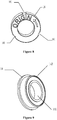
- the flanged bearing 14 includes an inner ring 141 and an outer ring 142, as shown in Figure 9 . With the design of the flange 152, the one-way bearing stop ring 15 is in contact with the outer ring of the flanged bearing 14.
- the reverse-wheel-set rotating shaft 11, the reverse wheel fixing frame 12, the one-way bearing stop ring 15, the one-way bearing 16 and the outer ring 142 of the flanged bearing constitute a stationary end.
- the reverse wheel shaft assembly 17, the E-shaped snap ring 13 and the inner ring 141 of the flanged bearing constitute a movable end.
- the reverse wheel assembly 17 can only rotate in a direction opposite to a banknote-feeding direction under the action of the one-way bearing 16.
- the one-way bearing stop ring 15 is in contact with only the outer ring of the flanged bearing 14, which allows the stationary end to be separated from the movable end by using the principle that the movements of the inner ring and the outer ring of the flanged bearing 14 are separated, thus, no friction is generated between the stationary end and the movable end, which ensures a free and smooth rotation of the reverse wheel assembly 17, thereby improving the service life of the banknote separating device and ensuring the reliability of its function.
Landscapes
- Engineering & Computer Science (AREA)
- Mechanical Engineering (AREA)
- Physics & Mathematics (AREA)
- General Physics & Mathematics (AREA)
- Sheets, Magazines, And Separation Thereof (AREA)
- Rolling Contact Bearings (AREA)
- Delivering By Means Of Belts And Rollers (AREA)
Abstract
Description
- This application claims the benefit of priority to Chinese patent application No.
201410613992.5 - The present application relates to the technology of financial self-service equipment, and particularly to a banknote separating device and a method for fixing a one-way bearing of a reverse wheel set of the banknote separating device.
- Currently, a one-way bearing is generally used in banknote separating mechanisms of financial equipment, and functions to restrict a banknote separating reverse wheel from rotating in a banknote-feeding direction, and only allow the banknote separating reverse wheel to rotate in a direction opposite to the banknote-feeding direction.
- Currently, one-way bearings are generally fixed by a way shown in
Figure 1 . The reverse wheel set includes a reversewheel rotating shaft 1, a reverse wheel fixing frame 2, an E-shaped snap ring 3, a one-way bearing housing 4, a one-way bearing 5, a flangedbearing 6, a reverse wheel shaft assembly 7 and aspacer 8. The way for fixing the one-way bearing 5 may be understood as follows. The reversewheel rotating shaft 1, the reverse wheel fixing frame 2, the one-way bearing housing 4, the one-way bearing 5, an outer ring of the flangedbearing 6, and thespacer 8 are each a stationary end, and the reverse wheel shaft assembly 7, the E-shaped snap ring, and an inner ring of the flangedbearing 6 are each a movable end. - In this fixing way, an end surface of the E-shaped snap ring of the movable end will squeeze and contact with an end surface of the one-way bearing 5 of the stationary end, thereby generating a friction resistance, which restricts the reverse wheel shaft assembly 7 from rotating freely. If the friction resistance is too large, the reverse wheel assembly 7 even cannot rotate. In case that the reverse wheel assembly 7 rotates unsmoothly or is incapable of rotation, a rubber portion of the reverse wheel assembly is apt to be partially abraded, which may enlarge a banknote separating gap. This defect, in a less severe case, may cause that the service life of the banknote separating device is significantly reduced and the banknote separating gap needs to be frequently adjusted, and in a severe case, may cause failure of the banknote separating function, which cannot meet the design requirement.
- For eliminating the defects in the conventional technology that the reverse wheel assembly rotates unsmoothly or is incapable of rotation due to the friction resistance, a banknote separating device is provided according to the present application, in which, a one-way bearing of a reverse wheel set of the banknote separating device is fixed by a new way, which effectively achieves separation of movement of a stationary end from movement of a movable end in the one-way bearing, thereby prolonging the service life of the banknote separating device and ensuring the reliability of its function.
- The banknote separating device according to the present application is applicable for a financial self-service equipment, the banknote separating device includes a banknote separating wheel set and a reverse wheel set for cooperating with the banknote separating wheel, and the reverse wheel set includes a reverse-wheel-set rotating shaft, a reverse wheel fixing frame, and a reverse wheel assembly. One end of the reverse wheel assembly sequentially passes through an E-shaped snap ring, a flanged bearing, a one-way bearing stop ring and a one-way bearing to be mounted to the reverse wheel fixing frame, wherein the one-way bearing and the reverse wheel fixing frame are coupled by the one-way bearing stop ring to form a stationary rigid body, and the one-way bearing stop ring is in contact with only an outer ring of the flanged bearing.
- Preferably, an outer peripheral surface of the one-way bearing stop ring is provided with a protruding strip extending in an axial direction of the one-way bearing stop ring, the reverse wheel fixing frame is provided with a groove for fitting with the protruding strip, and in an assembled state, the protruding strip of the one-way bearing stop ring is embedded into the groove of the reverse wheel fixing frame.
- Preferably, one end of the protruding strip protrudes from a first side of the one-way bearing stop ring, an outer peripheral surface of the one-way bearing is provided with a groove for fitting with the protruding strip, and in the assembled state, the one-way bearing is located at the first side of the one-way bearing stop ring, and an end, protruding from the first side of the one-way bearing stop ring, of the protruding strip is embedded into the groove in the outer peripheral surface of the one-way bearing.
- Preferably, the one-way bearing stop ring includes a second side opposite to the first side, an outer peripheral portion of the second side is configured as a flange, and in the assembled state, the flanged bearing is located at the second side of the one-way bearing stop ring, and the flange is in contact with the outer ring of the flanged bearing.
- Preferably, another end of the reverse wheel assembly sequentially passes through an E-shaped snap ring, a flanged bearing, and a spacer to be mounted to the reverse wheel fixing frame.
- A reverse wheel set is further provided according to the present application, which is applicable for a banknote separating device of a financial self-service equipment, the reverse wheel set includes a reverse-wheel-set rotating shaft, a reverse wheel fixing frame, and a reverse wheel assembly. One end of the reverse wheel assembly sequentially passes through an E-shaped snap ring, a flanged bearing, a one-way bearing stop ring and a one-way bearing to be mounted to the reverse wheel fixing frame, wherein the one-way bearing and the reverse wheel fixing frame are coupled by the one-way bearing stop ring to form a stationary rigid body, and the one-way bearing stop ring is in contact with only an outer ring of the flanged bearing.
- Preferably, an outer peripheral surface of the one-way bearing stop ring is provided with a protruding strip extending in an axial direction of the one-way bearing stop ring, the reverse wheel fixing frame is provided with a groove for fitting with the protruding strip, and in an assembled state, the protruding strip of the one-way bearing stop ring is embedded into the groove of the reverse wheel fixing frame.
- Preferably, one end of the protruding strip protrudes from a first side of the one-way bearing stop ring, an outer peripheral surface of the one-way bearing is provided with a groove for fitting with the protruding strip, and in the assembled state, the one-way bearing is located at the first side of the one-way bearing stop ring, and an end, protruding from the first side of the one-way bearing stop ring, of the protruding strip is embedded into the groove in the outer peripheral surface of the one-way bearing.
- Preferably, the one-way bearing stop ring includes a second side opposite to the first side, an outer peripheral portion of the second side is configured as a flange, and in the assembled state, the flanged bearing is located at the second side of the one-way bearing stop ring, and the flange is in contact with the outer ring of the flanged bearing.
- Preferably, another end of the reverse wheel assembly sequentially passes through an E-shaped snap ring, a flanged bearing, and a spacer to be mounted to the reverse wheel fixing frame.
- In the banknote separating device according to the present application, one end of the reverse wheel assembly sequentially passes through an E-shaped snap ring, a flanged bearing, a one-way bearing stop ring and a one-way bearing to be mounted to the reverse wheel fixing frame. The reverse-wheel-set rotating shaft, the reverse wheel fixing frame, the one-way bearing stop ring, the one-way bearing and the outer ring of the flanged bearing constitute a stationary end, and the reverse wheel shaft assembly, the E-shaped snap ring and the inner ring of the flanged bearing constitute a movable end. Due to the arrangement of the one-way bearing stop ring, the movements of the stationary end and the movable end of the one-way bearing are separated. Specifically, the protruding strip on the one-way bearing stop ring is embedded respectively into the groove in the reverse wheel fixing frame and the groove in the one-way bearing, thus the one-way bearing, the one-way bearing stop ring and the reverse wheel fixing frame are coupled to form a stationary rigid body. Further, the one-way bearing stop ring is in contact with only the outer ring of the flanged bearing by its protruding strip, thus the whole stationary end can be prevented from generating any friction with the movable end, which achieves the separation of the stationary end from the movable end, and thereby the reverse wheel assembly can rotate freely and smoothly without being subjected to any friction resistance during the rotation.
- For more clearly illustrating embodiments of the present application or the technical solutions in the conventional technology, drawings referred to describe the embodiments or the conventional technology will be briefly described hereinafter. Apparently, the drawings in the following description are only some examples of the present application, and for the person skilled in the art, other drawings may be obtained based on these drawings without any creative efforts.
-
Figure 1 is a schematic perspective exploded view showing the structure of a reverse wheel set in the conventional technology; -
Figure 2 is a schematic perspective view showing the structure of a reverse wheel set according to a preferred embodiment of the present application; -
Figure 3 is a sectional view of the reverse wheel set inFigure 2 taken along line A-A; -
Figure 4 is an enlarged view of part B inFigure 3 ; -
Figure 5 is an exploded view of the reverse wheel set inFigure 2 ; -
Figure 6 is a schematic perspective view showing the structure of a one-way bearing stop ring inFigure 5 ; -
Figure 7 is a schematic perspective view showing the structure of a reverse wheel fixing frame inFigure 5 ; -
Figure 8 is a schematic perspective view showing the structure of a one-way bearing inFigure 5 ; and -
Figure 9 is a schematic perspective view showing the structure of a flanged bearing inFigure 5 . - For further elaborating a banknote separating device and a method for fixing a one-way bearing of a reverse wheel set of the banknote separating device according to the present application, an embodiment of the present application is described in detail in conjunction with drawings.
- The banknote separating device according to this embodiment includes a banknote separating wheel set and a reverse wheel set cooperating with the banknote separating wheel. Since the banknote separating device according to this embodiment is characterized in the reverse wheel set, only the structure of the reverse wheel set is described in detail in this embodiment. Referring to
Figures 2 to 5 , thereverse wheel set 10 includes a reverse-wheel-set rotatingshaft 11, a reversewheel fixing frame 12 and areverse wheel assembly 17. One end of thereverse wheel assembly 17 sequentially passes through anE-shaped snap ring 13, a flangedbearing 14, a one-way bearingstop ring 15 and a one-way bearing 16 to be mounted to the reversewheel fixing frame 12. Another end of thereverse wheel assembly 17 sequentially passes through anE-shaped snap ring 13, a flangedbearing 14 and aspacer 18 to be mounted to the reverse wheel fixing frame. The one-way bearing 16 and the reversewheel fixing frame 12 are coupled by the one-way bearingstop ring 15 to form a stationary rigid body, and the one-way bearingstop ring 15 is in contact with only an outer ring of the flangedbearing 14. - In this embodiment, as shown in
Figures 6 and 7 , an outer peripheral surface of the one-way bearingstop ring 15 is provided with aprotruding strip 151 extending in an axial direction of the one-way bearing stop ring, and the reversewheel fixing frame 12 is provided with agroove 121 for fitting with the protruding strip. In an assembled state, as shown inFigure 4 , theprotruding strip 151 of the one-way bearingstop ring 15 is embedded into thegroove 121 of the reversewheel fixing frame 12. One end of theprotruding strip 151 protrudes from a first side of the one-way bearingstop ring 15, and an outer peripheral surface of the one-way bearing 15 is provided with agroove 161 for fitting with theprotruding strip 151, as shown inFigure 8 . In an assembled state, the one-way bearing 16 is located at the first side of the one-way bearingstop ring 15, and the end, protruding from the first side of the one-way bearingstop ring 15, of theprotruding strip 151 is embedded into thegroove 161 in the outer peripheral surface of the one-way bearing 16. With the arrangement of theprotruding strip 151, the one-way bearingstop ring 15 couples the one-way bearing 16 and the reversewheel fixing frame 12 to form the stationary rigid body. The design of the protruding strip may be equivalently varied, which is not limited to the structure illustrated in the drawings. - In addition, the one-way bearing
stop ring 15 includes a second side opposite to the first side, and an outer peripheral portion at the second side is configured as aflange 152. In an assembled state, the flangedbearing 14 is located at the second side of the one-way bearingstop ring 15, and theflange 152 is in contact with the outer ring of the flangedbearing 14, and reference may be made toFigure 4 . The flangedbearing 14 includes aninner ring 141 and anouter ring 142, as shown inFigure 9 . With the design of theflange 152, the one-way bearingstop ring 15 is in contact with the outer ring of the flangedbearing 14. - In this embodiment, the reverse-wheel-set rotating
shaft 11, the reversewheel fixing frame 12, the one-way bearingstop ring 15, the one-way bearing 16 and theouter ring 142 of the flanged bearing constitute a stationary end. The reversewheel shaft assembly 17, theE-shaped snap ring 13 and theinner ring 141 of the flanged bearing constitute a movable end. Thereverse wheel assembly 17 can only rotate in a direction opposite to a banknote-feeding direction under the action of the one-way bearing 16. Under the action of theflange 152, the one-waybearing stop ring 15 is in contact with only the outer ring of theflanged bearing 14, which allows the stationary end to be separated from the movable end by using the principle that the movements of the inner ring and the outer ring of theflanged bearing 14 are separated, thus, no friction is generated between the stationary end and the movable end, which ensures a free and smooth rotation of thereverse wheel assembly 17, thereby improving the service life of the banknote separating device and ensuring the reliability of its function. - The above description is only preferred embodiments of the present application. It should be noted that, the above preferred embodiments should not be deemed as a limitation to the present application, and the scope of the present application is defined by the claims of the present application. For the person skilled in the art, several improvements and modifications may be made to the present application without departing from the spirit and scope of the present application, and these improvements and modifications are also deemed to fall into the scope of the present application.
Claims (10)
- A banknote separating device, applicable for a financial self-service equipment, the banknote separating device comprising a banknote separating wheel set and a reverse wheel set for cooperating with the banknote separating wheel, the reverse wheel set comprising a reverse-wheel-set rotating shaft, a reverse wheel fixing frame, and a reverse wheel assembly, wherein one end of the reverse wheel assembly sequentially passes through an E-shaped snap ring, a flanged bearing, a one-way bearing stop ring and a one-way bearing to be mounted to the reverse wheel fixing frame, wherein the one-way bearing and the reverse wheel fixing frame are coupled by the one-way bearing stop ring to form a stationary rigid body, and the one-way bearing stop ring is in contact with only an outer ring of the flanged bearing.
- The banknote separating device according to claim 1, wherein an outer peripheral surface of the one-way bearing stop ring is provided with a protruding strip extending in an axial direction of the one-way bearing stop ring, the reverse wheel fixing frame is provided with a groove for fitting with the protruding strip, and in an assembled state, the protruding strip of the one-way bearing stop ring is embedded into the groove of the reverse wheel fixing frame.
- The banknote separating device according to claim 2, wherein one end of the protruding strip protrudes from a first side of the one-way bearing stop ring, an outer peripheral surface of the one-way bearing is provided with a groove for fitting with the protruding strip, and in the assembled state, the one-way bearing is located at the first side of the one-way bearing stop ring, and an end, protruding from the first side of the one-way bearing stop ring, of the protruding strip is embedded into the groove in the outer peripheral surface of the one-way bearing.
- The banknote separating device according to claim 2, wherein the one-way bearing stop ring comprises a second side opposite to the first side, an outer peripheral portion of the second side is configured as a flange, and in the assembled state, the flanged bearing is located at the second side of the one-way bearing stop ring, and the flange is in contact with the outer ring of the flanged bearing.
- The banknote separating device according to claim 1, wherein another end of the reverse wheel assembly sequentially passes through an E-shaped snap ring, a flanged bearing, and a spacer to be mounted to the reverse wheel fixing frame.
- A reverse wheel set, applicable for a banknote separating device of a financial self-service equipment, the reverse wheel set comprising a reverse-wheel-set rotating shaft, a reverse wheel fixing frame, and a reverse wheel assembly, wherein one end of the reverse wheel assembly sequentially passes through an E-shaped snap ring, a flanged bearing, a one-way bearing stop ring and a one-way bearing to be mounted to the reverse wheel fixing frame, wherein the one-way bearing and the reverse wheel fixing frame are coupled by the one-way bearing stop ring to form a stationary rigid body, and the one-way bearing stop ring is in contact with only an outer ring of the flanged bearing.
- The reverse wheel set according to claim 6, wherein an outer peripheral surface of the one-way bearing stop ring is provided with a protruding strip extending in an axial direction of the one-way bearing stop ring, the reverse wheel fixing frame is provided with a groove for fitting with the protruding strip, and in an assembled state, the protruding strip of the one-way bearing stop ring is embedded into the groove of the reverse wheel fixing frame.
- The reverse wheel set according to claim 7, wherein one end of the protruding strip protrudes from a first side of the one-way bearing stop ring, an outer peripheral surface of the one-way bearing is provided with a groove for fitting with the protruding strip, and in the assembled state, the one-way bearing is located at the first side of the one-way bearing stop ring, and an end, protruding from the first side of the one-way bearing stop ring, of the protruding strip is embedded into the groove in the outer peripheral surface of the one-way bearing.
- The reverse wheel set according to claim 7, wherein the one-way bearing stop ring comprises a second side opposite to the first side, an outer peripheral portion of the second side is configured as a flange, and in the assembled state, the flanged bearing is located at the second side of the one-way bearing stop ring, and the flange is in contact with the outer ring of the flanged bearing.
- The reverse wheel set according to claim 6, wherein another end of the reverse wheel assembly sequentially passes through an E-shaped snap ring, a flanged bearing, and a spacer to be mounted to the reverse wheel fixing frame.
Applications Claiming Priority (2)
| Application Number | Priority Date | Filing Date | Title |
|---|---|---|---|
| CN201410613992.5A CN104355144B (en) | 2014-11-03 | 2014-11-03 | Bank note distributing device and reversing wheel set thereof |
| PCT/CN2015/086314 WO2016070661A1 (en) | 2014-11-03 | 2015-08-07 | Paper money distributing device and reversing wheel set thereof |
Publications (3)
| Publication Number | Publication Date |
|---|---|
| EP3216728A1 true EP3216728A1 (en) | 2017-09-13 |
| EP3216728A4 EP3216728A4 (en) | 2018-01-17 |
| EP3216728B1 EP3216728B1 (en) | 2019-10-23 |
Family
ID=52522491
Family Applications (1)
| Application Number | Title | Priority Date | Filing Date |
|---|---|---|---|
| EP15857642.1A Active EP3216728B1 (en) | 2014-11-03 | 2015-08-07 | Reversing wheel set and paper money distributing device |
Country Status (5)
| Country | Link |
|---|---|
| US (1) | US9840383B2 (en) |
| EP (1) | EP3216728B1 (en) |
| CN (1) | CN104355144B (en) |
| RU (1) | RU2663582C1 (en) |
| WO (1) | WO2016070661A1 (en) |
Families Citing this family (5)
| Publication number | Priority date | Publication date | Assignee | Title |
|---|---|---|---|---|
| CN104355144B (en) * | 2014-11-03 | 2017-04-26 | 广州广电运通金融电子股份有限公司 | Bank note distributing device and reversing wheel set thereof |
| CN106023421A (en) * | 2016-05-20 | 2016-10-12 | 新达通科技股份有限公司 | Reversing wheel mechanism and banknote sorting device |
| CN106875550B (en) * | 2017-01-19 | 2023-08-11 | 深圳怡化电脑股份有限公司 | Cash roller mechanism and automatic teller machine |
| CN108502581B (en) * | 2018-03-23 | 2020-08-18 | 深圳怡化电脑股份有限公司 | Medium separation mechanism and self-service financial equipment |
| CN109538054A (en) * | 2018-12-04 | 2019-03-29 | 长沙微联精密机械有限公司 | A kind of single effect rotary damper |
Family Cites Families (18)
| Publication number | Priority date | Publication date | Assignee | Title |
|---|---|---|---|---|
| US6302393B1 (en) * | 1998-09-17 | 2001-10-16 | Diebold, Incorporated | Media storage system for automated banking machine |
| JP3933024B2 (en) * | 2002-09-27 | 2007-06-20 | 松下電器産業株式会社 | Separating paper feeder |
| JP3929960B2 (en) * | 2003-10-27 | 2007-06-13 | 京セラミタ株式会社 | Paper feed unit |
| JP4340560B2 (en) | 2004-02-27 | 2009-10-07 | 株式会社ニフコ | A clutch device for transmitting driving force to a member to be transmitted such as a paper feed roller in a copying machine, facsimile, printer, etc. |
| US8052145B2 (en) * | 2006-06-28 | 2011-11-08 | De La Rue International Limited | Document handling apparatus |
| JP4988467B2 (en) * | 2007-07-26 | 2012-08-01 | 京セラドキュメントソリューションズ株式会社 | Paper supply device |
| CN201654835U (en) * | 2009-08-11 | 2010-11-24 | 上海古鳌电子机械有限公司 | Double-bearing unidirectional adjustable bill-pressing structure |
| CN202022599U (en) * | 2011-04-14 | 2011-11-02 | 崴强科技股份有限公司 | paper intake mechanism |
| TW201318877A (en) * | 2011-11-11 | 2013-05-16 | Primax Electronics Ltd | Automatic document feeder |
| TWI466812B (en) * | 2012-07-20 | 2015-01-01 | Primax Electronics Ltd | Double-side document feeding device |
| US8979088B2 (en) * | 2012-11-02 | 2015-03-17 | Canon Kabushiki Kaisha | Sheet feeding apparatus and image forming apparatus |
| US9540192B2 (en) * | 2013-11-01 | 2017-01-10 | Canon Kabushiki Kaisha | Sheet feeding apparatus and image forming apparatus |
| US8998208B1 (en) * | 2013-11-25 | 2015-04-07 | Foxlink Image Technology Co., Ltd. | Transmission device of automatic document feeder |
| CN103708250B (en) * | 2013-12-24 | 2016-01-20 | 广州广电运通金融电子股份有限公司 | A kind of separation device of sheet kind medium and financial self-service equipment |
| CN103646465A (en) * | 2013-12-24 | 2014-03-19 | 广州广电运通金融电子股份有限公司 | Banknote collection and separation device and financial self-service equipment |
| CN103700185B (en) * | 2013-12-26 | 2016-08-17 | 上海古鳌电子科技股份有限公司 | A kind of paper currency inlet mechanism of paper currency sorter |
| CN203781421U (en) * | 2014-03-19 | 2014-08-20 | 山东新北洋信息技术股份有限公司 | Sheet medium separation mechanism and sheet medium processing device |
| CN104355144B (en) | 2014-11-03 | 2017-04-26 | 广州广电运通金融电子股份有限公司 | Bank note distributing device and reversing wheel set thereof |
-
2014
- 2014-11-03 CN CN201410613992.5A patent/CN104355144B/en active Active
-
2015
- 2015-08-07 WO PCT/CN2015/086314 patent/WO2016070661A1/en not_active Ceased
- 2015-08-07 US US15/522,223 patent/US9840383B2/en not_active Expired - Fee Related
- 2015-08-07 RU RU2017118267A patent/RU2663582C1/en not_active IP Right Cessation
- 2015-08-07 EP EP15857642.1A patent/EP3216728B1/en active Active
Also Published As
| Publication number | Publication date |
|---|---|
| EP3216728A4 (en) | 2018-01-17 |
| EP3216728B1 (en) | 2019-10-23 |
| CN104355144B (en) | 2017-04-26 |
| US20170313531A1 (en) | 2017-11-02 |
| US9840383B2 (en) | 2017-12-12 |
| WO2016070661A1 (en) | 2016-05-12 |
| RU2663582C1 (en) | 2018-08-07 |
| CN104355144A (en) | 2015-02-18 |
Similar Documents
| Publication | Publication Date | Title |
|---|---|---|
| EP3216728A1 (en) | Paper money distributing device and reversing wheel set thereof | |
| EP3477137A1 (en) | Box type sealing struture and conical roller bearing | |
| US9261185B2 (en) | Drive transmission mechanism and image forming apparatus including same | |
| US3814446A (en) | Sealing arrangement | |
| US11406030B2 (en) | Rollable flexible display device | |
| US9447816B2 (en) | Bearing assembly | |
| CN105473881A (en) | Large roller bearing comprising a labyrinth seal | |
| JP2013020191A (en) | Document platen opening/closing device and oa equipment | |
| JP2009210024A (en) | Reverse input preventing clutch | |
| EP3763956A1 (en) | Radial foil bearing | |
| HK1242670A1 (en) | Reversing wheel set and paper money distributing device | |
| US10594880B2 (en) | Lock lever structure, unit, and image forming apparatus | |
| CN201976380U (en) | Stable synchronizing mechanism of sliding cover | |
| NZ720917A (en) | Linear gear shift power transfer mechanism | |
| US2281010A (en) | Bearing seal | |
| CN210686666U (en) | Sliding bearing support structure, sliding bearing assembly and reactor | |
| CN107975530B (en) | Roller assembly and air conditioner comprising same | |
| US20120257922A1 (en) | Pivot pin structure | |
| CN118934824A (en) | Hinge mechanism and electronic device | |
| AU2017232795A1 (en) | Anti-binding ball swivel | |
| KR20120112156A (en) | Tilt hinge and electronic apparatus with the tilt hinge | |
| HK1242670B (en) | Reversing wheel set and paper money distributing device | |
| CN110043559B (en) | Sliding bearing support structure, sliding bearing assembly and reactor | |
| CN211003284U (en) | Positive feedback centrifugal damping carrier roller | |
| US7748923B2 (en) | Gap-forming element for mounting on a shaft |
Legal Events
| Date | Code | Title | Description |
|---|---|---|---|
| STAA | Information on the status of an ep patent application or granted ep patent |
Free format text: STATUS: THE INTERNATIONAL PUBLICATION HAS BEEN MADE |
|
| PUAI | Public reference made under article 153(3) epc to a published international application that has entered the european phase |
Free format text: ORIGINAL CODE: 0009012 |
|
| STAA | Information on the status of an ep patent application or granted ep patent |
Free format text: STATUS: REQUEST FOR EXAMINATION WAS MADE |
|
| 17P | Request for examination filed |
Effective date: 20170504 |
|
| AK | Designated contracting states |
Kind code of ref document: A1 Designated state(s): AL AT BE BG CH CY CZ DE DK EE ES FI FR GB GR HR HU IE IS IT LI LT LU LV MC MK MT NL NO PL PT RO RS SE SI SK SM TR |
|
| AX | Request for extension of the european patent |
Extension state: BA ME |
|
| A4 | Supplementary search report drawn up and despatched |
Effective date: 20171220 |
|
| RIC1 | Information provided on ipc code assigned before grant |
Ipc: B65H 3/06 20060101AFI20171214BHEP |
|
| DAV | Request for validation of the european patent (deleted) | ||
| DAX | Request for extension of the european patent (deleted) | ||
| REG | Reference to a national code |
Ref country code: HK Ref legal event code: DE Ref document number: 1242670 Country of ref document: HK |
|
| RIC1 | Information provided on ipc code assigned before grant |
Ipc: B65H 3/52 20060101AFI20180927BHEP Ipc: G07D 11/00 20060101ALI20180927BHEP |
|
| STAA | Information on the status of an ep patent application or granted ep patent |
Free format text: STATUS: EXAMINATION IS IN PROGRESS |
|
| 17Q | First examination report despatched |
Effective date: 20181123 |
|
| REG | Reference to a national code |
Ref country code: DE Ref legal event code: R079 Ref document number: 602015040495 Country of ref document: DE Free format text: PREVIOUS MAIN CLASS: B65H0003060000 Ipc: B65H0003520000 |
|
| RIC1 | Information provided on ipc code assigned before grant |
Ipc: G07D 11/00 20190101ALI20190327BHEP Ipc: B65H 3/52 20060101AFI20190327BHEP Ipc: G07D 11/25 20190101ALI20190327BHEP |
|
| GRAP | Despatch of communication of intention to grant a patent |
Free format text: ORIGINAL CODE: EPIDOSNIGR1 |
|
| STAA | Information on the status of an ep patent application or granted ep patent |
Free format text: STATUS: GRANT OF PATENT IS INTENDED |
|
| INTG | Intention to grant announced |
Effective date: 20190509 |
|
| GRAS | Grant fee paid |
Free format text: ORIGINAL CODE: EPIDOSNIGR3 |
|
| GRAA | (expected) grant |
Free format text: ORIGINAL CODE: 0009210 |
|
| STAA | Information on the status of an ep patent application or granted ep patent |
Free format text: STATUS: THE PATENT HAS BEEN GRANTED |
|
| AK | Designated contracting states |
Kind code of ref document: B1 Designated state(s): AL AT BE BG CH CY CZ DE DK EE ES FI FR GB GR HR HU IE IS IT LI LT LU LV MC MK MT NL NO PL PT RO RS SE SI SK SM TR |
|
| REG | Reference to a national code |
Ref country code: GB Ref legal event code: FG4D |
|
| REG | Reference to a national code |
Ref country code: CH Ref legal event code: EP |
|
| REG | Reference to a national code |
Ref country code: IE Ref legal event code: FG4D |
|
| REG | Reference to a national code |
Ref country code: DE Ref legal event code: R096 Ref document number: 602015040495 Country of ref document: DE |
|
| REG | Reference to a national code |
Ref country code: AT Ref legal event code: REF Ref document number: 1193421 Country of ref document: AT Kind code of ref document: T Effective date: 20191115 |
|
| REG | Reference to a national code |
Ref country code: NL Ref legal event code: MP Effective date: 20191023 |
|
| REG | Reference to a national code |
Ref country code: LT Ref legal event code: MG4D |
|
| PG25 | Lapsed in a contracting state [announced via postgrant information from national office to epo] |
Ref country code: FI Free format text: LAPSE BECAUSE OF FAILURE TO SUBMIT A TRANSLATION OF THE DESCRIPTION OR TO PAY THE FEE WITHIN THE PRESCRIBED TIME-LIMIT Effective date: 20191023 Ref country code: BG Free format text: LAPSE BECAUSE OF FAILURE TO SUBMIT A TRANSLATION OF THE DESCRIPTION OR TO PAY THE FEE WITHIN THE PRESCRIBED TIME-LIMIT Effective date: 20200123 Ref country code: PT Free format text: LAPSE BECAUSE OF FAILURE TO SUBMIT A TRANSLATION OF THE DESCRIPTION OR TO PAY THE FEE WITHIN THE PRESCRIBED TIME-LIMIT Effective date: 20200224 Ref country code: SE Free format text: LAPSE BECAUSE OF FAILURE TO SUBMIT A TRANSLATION OF THE DESCRIPTION OR TO PAY THE FEE WITHIN THE PRESCRIBED TIME-LIMIT Effective date: 20191023 Ref country code: LV Free format text: LAPSE BECAUSE OF FAILURE TO SUBMIT A TRANSLATION OF THE DESCRIPTION OR TO PAY THE FEE WITHIN THE PRESCRIBED TIME-LIMIT Effective date: 20191023 Ref country code: NL Free format text: LAPSE BECAUSE OF FAILURE TO SUBMIT A TRANSLATION OF THE DESCRIPTION OR TO PAY THE FEE WITHIN THE PRESCRIBED TIME-LIMIT Effective date: 20191023 Ref country code: LT Free format text: LAPSE BECAUSE OF FAILURE TO SUBMIT A TRANSLATION OF THE DESCRIPTION OR TO PAY THE FEE WITHIN THE PRESCRIBED TIME-LIMIT Effective date: 20191023 Ref country code: GR Free format text: LAPSE BECAUSE OF FAILURE TO SUBMIT A TRANSLATION OF THE DESCRIPTION OR TO PAY THE FEE WITHIN THE PRESCRIBED TIME-LIMIT Effective date: 20200124 Ref country code: NO Free format text: LAPSE BECAUSE OF FAILURE TO SUBMIT A TRANSLATION OF THE DESCRIPTION OR TO PAY THE FEE WITHIN THE PRESCRIBED TIME-LIMIT Effective date: 20200123 Ref country code: PL Free format text: LAPSE BECAUSE OF FAILURE TO SUBMIT A TRANSLATION OF THE DESCRIPTION OR TO PAY THE FEE WITHIN THE PRESCRIBED TIME-LIMIT Effective date: 20191023 |
|
| PG25 | Lapsed in a contracting state [announced via postgrant information from national office to epo] |
Ref country code: HR Free format text: LAPSE BECAUSE OF FAILURE TO SUBMIT A TRANSLATION OF THE DESCRIPTION OR TO PAY THE FEE WITHIN THE PRESCRIBED TIME-LIMIT Effective date: 20191023 Ref country code: RS Free format text: LAPSE BECAUSE OF FAILURE TO SUBMIT A TRANSLATION OF THE DESCRIPTION OR TO PAY THE FEE WITHIN THE PRESCRIBED TIME-LIMIT Effective date: 20191023 Ref country code: IS Free format text: LAPSE BECAUSE OF FAILURE TO SUBMIT A TRANSLATION OF THE DESCRIPTION OR TO PAY THE FEE WITHIN THE PRESCRIBED TIME-LIMIT Effective date: 20200224 |
|
| PG25 | Lapsed in a contracting state [announced via postgrant information from national office to epo] |
Ref country code: AL Free format text: LAPSE BECAUSE OF FAILURE TO SUBMIT A TRANSLATION OF THE DESCRIPTION OR TO PAY THE FEE WITHIN THE PRESCRIBED TIME-LIMIT Effective date: 20191023 |
|
| REG | Reference to a national code |
Ref country code: DE Ref legal event code: R097 Ref document number: 602015040495 Country of ref document: DE |
|
| PG2D | Information on lapse in contracting state deleted |
Ref country code: IS |
|
| PG25 | Lapsed in a contracting state [announced via postgrant information from national office to epo] |
Ref country code: CZ Free format text: LAPSE BECAUSE OF FAILURE TO SUBMIT A TRANSLATION OF THE DESCRIPTION OR TO PAY THE FEE WITHIN THE PRESCRIBED TIME-LIMIT Effective date: 20191023 Ref country code: ES Free format text: LAPSE BECAUSE OF FAILURE TO SUBMIT A TRANSLATION OF THE DESCRIPTION OR TO PAY THE FEE WITHIN THE PRESCRIBED TIME-LIMIT Effective date: 20191023 Ref country code: RO Free format text: LAPSE BECAUSE OF FAILURE TO SUBMIT A TRANSLATION OF THE DESCRIPTION OR TO PAY THE FEE WITHIN THE PRESCRIBED TIME-LIMIT Effective date: 20191023 Ref country code: EE Free format text: LAPSE BECAUSE OF FAILURE TO SUBMIT A TRANSLATION OF THE DESCRIPTION OR TO PAY THE FEE WITHIN THE PRESCRIBED TIME-LIMIT Effective date: 20191023 Ref country code: DK Free format text: LAPSE BECAUSE OF FAILURE TO SUBMIT A TRANSLATION OF THE DESCRIPTION OR TO PAY THE FEE WITHIN THE PRESCRIBED TIME-LIMIT Effective date: 20191023 Ref country code: IS Free format text: LAPSE BECAUSE OF FAILURE TO SUBMIT A TRANSLATION OF THE DESCRIPTION OR TO PAY THE FEE WITHIN THE PRESCRIBED TIME-LIMIT Effective date: 20200223 |
|
| PLBE | No opposition filed within time limit |
Free format text: ORIGINAL CODE: 0009261 |
|
| STAA | Information on the status of an ep patent application or granted ep patent |
Free format text: STATUS: NO OPPOSITION FILED WITHIN TIME LIMIT |
|
| PG25 | Lapsed in a contracting state [announced via postgrant information from national office to epo] |
Ref country code: SM Free format text: LAPSE BECAUSE OF FAILURE TO SUBMIT A TRANSLATION OF THE DESCRIPTION OR TO PAY THE FEE WITHIN THE PRESCRIBED TIME-LIMIT Effective date: 20191023 Ref country code: SK Free format text: LAPSE BECAUSE OF FAILURE TO SUBMIT A TRANSLATION OF THE DESCRIPTION OR TO PAY THE FEE WITHIN THE PRESCRIBED TIME-LIMIT Effective date: 20191023 |
|
| 26N | No opposition filed |
Effective date: 20200724 |
|
| PG25 | Lapsed in a contracting state [announced via postgrant information from national office to epo] |
Ref country code: SI Free format text: LAPSE BECAUSE OF FAILURE TO SUBMIT A TRANSLATION OF THE DESCRIPTION OR TO PAY THE FEE WITHIN THE PRESCRIBED TIME-LIMIT Effective date: 20191023 |
|
| REG | Reference to a national code |
Ref country code: AT Ref legal event code: UEP Ref document number: 1193421 Country of ref document: AT Kind code of ref document: T Effective date: 20191023 |
|
| REG | Reference to a national code |
Ref country code: DE Ref legal event code: R119 Ref document number: 602015040495 Country of ref document: DE |
|
| PG25 | Lapsed in a contracting state [announced via postgrant information from national office to epo] |
Ref country code: MC Free format text: LAPSE BECAUSE OF FAILURE TO SUBMIT A TRANSLATION OF THE DESCRIPTION OR TO PAY THE FEE WITHIN THE PRESCRIBED TIME-LIMIT Effective date: 20191023 |
|
| REG | Reference to a national code |
Ref country code: CH Ref legal event code: PL |
|
| GBPC | Gb: european patent ceased through non-payment of renewal fee |
Effective date: 20200807 |
|
| PG25 | Lapsed in a contracting state [announced via postgrant information from national office to epo] |
Ref country code: LU Free format text: LAPSE BECAUSE OF NON-PAYMENT OF DUE FEES Effective date: 20200807 Ref country code: LI Free format text: LAPSE BECAUSE OF NON-PAYMENT OF DUE FEES Effective date: 20200831 Ref country code: CH Free format text: LAPSE BECAUSE OF NON-PAYMENT OF DUE FEES Effective date: 20200831 |
|
| REG | Reference to a national code |
Ref country code: BE Ref legal event code: MM Effective date: 20200831 |
|
| PG25 | Lapsed in a contracting state [announced via postgrant information from national office to epo] |
Ref country code: DE Free format text: LAPSE BECAUSE OF NON-PAYMENT OF DUE FEES Effective date: 20210302 Ref country code: FR Free format text: LAPSE BECAUSE OF NON-PAYMENT OF DUE FEES Effective date: 20200831 |
|
| PG25 | Lapsed in a contracting state [announced via postgrant information from national office to epo] |
Ref country code: IE Free format text: LAPSE BECAUSE OF NON-PAYMENT OF DUE FEES Effective date: 20200807 Ref country code: GB Free format text: LAPSE BECAUSE OF NON-PAYMENT OF DUE FEES Effective date: 20200807 Ref country code: BE Free format text: LAPSE BECAUSE OF NON-PAYMENT OF DUE FEES Effective date: 20200831 |
|
| REG | Reference to a national code |
Ref country code: AT Ref legal event code: MM01 Ref document number: 1193421 Country of ref document: AT Kind code of ref document: T Effective date: 20200807 |
|
| PG25 | Lapsed in a contracting state [announced via postgrant information from national office to epo] |
Ref country code: IT Free format text: LAPSE BECAUSE OF NON-PAYMENT OF DUE FEES Effective date: 20200807 Ref country code: AT Free format text: LAPSE BECAUSE OF NON-PAYMENT OF DUE FEES Effective date: 20200807 |
|
| PG25 | Lapsed in a contracting state [announced via postgrant information from national office to epo] |
Ref country code: MT Free format text: LAPSE BECAUSE OF FAILURE TO SUBMIT A TRANSLATION OF THE DESCRIPTION OR TO PAY THE FEE WITHIN THE PRESCRIBED TIME-LIMIT Effective date: 20191023 Ref country code: CY Free format text: LAPSE BECAUSE OF FAILURE TO SUBMIT A TRANSLATION OF THE DESCRIPTION OR TO PAY THE FEE WITHIN THE PRESCRIBED TIME-LIMIT Effective date: 20191023 |
|
| PG25 | Lapsed in a contracting state [announced via postgrant information from national office to epo] |
Ref country code: MK Free format text: LAPSE BECAUSE OF FAILURE TO SUBMIT A TRANSLATION OF THE DESCRIPTION OR TO PAY THE FEE WITHIN THE PRESCRIBED TIME-LIMIT Effective date: 20191023 |
|
| PG25 | Lapsed in a contracting state [announced via postgrant information from national office to epo] |
Ref country code: TR Free format text: LAPSE BECAUSE OF NON-PAYMENT OF DUE FEES Effective date: 20200807 |