EP3216547A1 - Verfahren zum herstellen einer schaufel für eine strömungsmaschine - Google Patents
Verfahren zum herstellen einer schaufel für eine strömungsmaschine Download PDFInfo
- Publication number
- EP3216547A1 EP3216547A1 EP17159757.8A EP17159757A EP3216547A1 EP 3216547 A1 EP3216547 A1 EP 3216547A1 EP 17159757 A EP17159757 A EP 17159757A EP 3216547 A1 EP3216547 A1 EP 3216547A1
- Authority
- EP
- European Patent Office
- Prior art keywords
- blade
- generative
- root
- support surface
- tial alloy
- Prior art date
- Legal status (The legal status is an assumption and is not a legal conclusion. Google has not performed a legal analysis and makes no representation as to the accuracy of the status listed.)
- Granted
Links
- 238000004519 manufacturing process Methods 0.000 title claims abstract description 19
- 239000012530 fluid Substances 0.000 title 1
- 239000000463 material Substances 0.000 claims abstract description 42
- 238000000034 method Methods 0.000 claims abstract description 30
- 239000000843 powder Substances 0.000 claims abstract description 21
- 239000000203 mixture Substances 0.000 claims abstract description 16
- 238000005245 sintering Methods 0.000 claims abstract description 8
- 239000000919 ceramic Substances 0.000 claims abstract description 6
- 229910045601 alloy Inorganic materials 0.000 claims description 25
- 239000000956 alloy Substances 0.000 claims description 25
- 229910010038 TiAl Inorganic materials 0.000 claims description 22
- 238000010276 construction Methods 0.000 claims description 18
- 238000000926 separation method Methods 0.000 claims description 12
- 229910052782 aluminium Inorganic materials 0.000 claims description 11
- 229910052750 molybdenum Inorganic materials 0.000 claims description 11
- 229910052710 silicon Inorganic materials 0.000 claims description 11
- 229910052735 hafnium Inorganic materials 0.000 claims description 9
- 229910052758 niobium Inorganic materials 0.000 claims description 9
- 238000002844 melting Methods 0.000 claims description 8
- 230000008018 melting Effects 0.000 claims description 8
- 229910052726 zirconium Inorganic materials 0.000 claims description 8
- 229910006281 γ-TiAl Inorganic materials 0.000 claims description 8
- 229910052719 titanium Inorganic materials 0.000 claims description 6
- 238000000137 annealing Methods 0.000 claims description 5
- 230000032683 aging Effects 0.000 claims description 4
- 238000001513 hot isostatic pressing Methods 0.000 claims description 4
- 238000005275 alloying Methods 0.000 claims description 3
- 229910052799 carbon Inorganic materials 0.000 claims description 3
- 230000003628 erosive effect Effects 0.000 claims description 3
- 229910052721 tungsten Inorganic materials 0.000 claims description 3
- 229910052720 vanadium Inorganic materials 0.000 claims description 3
- 229910052727 yttrium Inorganic materials 0.000 claims description 3
- 239000013078 crystal Substances 0.000 description 12
- 238000010894 electron beam technology Methods 0.000 description 8
- 239000010955 niobium Substances 0.000 description 6
- 238000007711 solidification Methods 0.000 description 5
- 230000008023 solidification Effects 0.000 description 5
- 238000005304 joining Methods 0.000 description 4
- 239000000470 constituent Substances 0.000 description 3
- 230000004927 fusion Effects 0.000 description 3
- 230000003647 oxidation Effects 0.000 description 3
- 238000007254 oxidation reaction Methods 0.000 description 3
- ZOKXTWBITQBERF-UHFFFAOYSA-N Molybdenum Chemical compound [Mo] ZOKXTWBITQBERF-UHFFFAOYSA-N 0.000 description 2
- 239000000654 additive Substances 0.000 description 2
- 230000000996 additive effect Effects 0.000 description 2
- 238000005266 casting Methods 0.000 description 2
- 239000011733 molybdenum Substances 0.000 description 2
- 230000006835 compression Effects 0.000 description 1
- 238000007906 compression Methods 0.000 description 1
- 238000011161 development Methods 0.000 description 1
- 230000018109 developmental process Effects 0.000 description 1
- 238000010438 heat treatment Methods 0.000 description 1
- 239000012535 impurity Substances 0.000 description 1
- 239000004615 ingredient Substances 0.000 description 1
- 238000002955 isolation Methods 0.000 description 1
- 239000007788 liquid Substances 0.000 description 1
- 238000003754 machining Methods 0.000 description 1
- 239000000155 melt Substances 0.000 description 1
- GUCVJGMIXFAOAE-UHFFFAOYSA-N niobium atom Chemical compound [Nb] GUCVJGMIXFAOAE-UHFFFAOYSA-N 0.000 description 1
- 239000011148 porous material Substances 0.000 description 1
- 239000002244 precipitate Substances 0.000 description 1
- 238000000110 selective laser sintering Methods 0.000 description 1
- 230000008646 thermal stress Effects 0.000 description 1
Images

Classifications
-
- F—MECHANICAL ENGINEERING; LIGHTING; HEATING; WEAPONS; BLASTING
- F01—MACHINES OR ENGINES IN GENERAL; ENGINE PLANTS IN GENERAL; STEAM ENGINES
- F01D—NON-POSITIVE DISPLACEMENT MACHINES OR ENGINES, e.g. STEAM TURBINES
- F01D5/00—Blades; Blade-carrying members; Heating, heat-insulating, cooling or antivibration means on the blades or the members
- F01D5/12—Blades
- F01D5/28—Selecting particular materials; Particular measures relating thereto; Measures against erosion or corrosion
-
- B—PERFORMING OPERATIONS; TRANSPORTING
- B22—CASTING; POWDER METALLURGY
- B22F—WORKING METALLIC POWDER; MANUFACTURE OF ARTICLES FROM METALLIC POWDER; MAKING METALLIC POWDER; APPARATUS OR DEVICES SPECIALLY ADAPTED FOR METALLIC POWDER
- B22F10/00—Additive manufacturing of workpieces or articles from metallic powder
- B22F10/20—Direct sintering or melting
- B22F10/28—Powder bed fusion, e.g. selective laser melting [SLM] or electron beam melting [EBM]
-
- B—PERFORMING OPERATIONS; TRANSPORTING
- B22—CASTING; POWDER METALLURGY
- B22F—WORKING METALLIC POWDER; MANUFACTURE OF ARTICLES FROM METALLIC POWDER; MAKING METALLIC POWDER; APPARATUS OR DEVICES SPECIALLY ADAPTED FOR METALLIC POWDER
- B22F10/00—Additive manufacturing of workpieces or articles from metallic powder
- B22F10/60—Treatment of workpieces or articles after build-up
- B22F10/64—Treatment of workpieces or articles after build-up by thermal means
-
- B—PERFORMING OPERATIONS; TRANSPORTING
- B22—CASTING; POWDER METALLURGY
- B22F—WORKING METALLIC POWDER; MANUFACTURE OF ARTICLES FROM METALLIC POWDER; MAKING METALLIC POWDER; APPARATUS OR DEVICES SPECIALLY ADAPTED FOR METALLIC POWDER
- B22F3/00—Manufacture of workpieces or articles from metallic powder characterised by the manner of compacting or sintering; Apparatus specially adapted therefor ; Presses and furnaces
- B22F3/12—Both compacting and sintering
- B22F3/14—Both compacting and sintering simultaneously
- B22F3/15—Hot isostatic pressing
-
- B—PERFORMING OPERATIONS; TRANSPORTING
- B22—CASTING; POWDER METALLURGY
- B22F—WORKING METALLIC POWDER; MANUFACTURE OF ARTICLES FROM METALLIC POWDER; MAKING METALLIC POWDER; APPARATUS OR DEVICES SPECIALLY ADAPTED FOR METALLIC POWDER
- B22F3/00—Manufacture of workpieces or articles from metallic powder characterised by the manner of compacting or sintering; Apparatus specially adapted therefor ; Presses and furnaces
- B22F3/24—After-treatment of workpieces or articles
-
- B—PERFORMING OPERATIONS; TRANSPORTING
- B22—CASTING; POWDER METALLURGY
- B22F—WORKING METALLIC POWDER; MANUFACTURE OF ARTICLES FROM METALLIC POWDER; MAKING METALLIC POWDER; APPARATUS OR DEVICES SPECIALLY ADAPTED FOR METALLIC POWDER
- B22F5/00—Manufacture of workpieces or articles from metallic powder characterised by the special shape of the product
- B22F5/04—Manufacture of workpieces or articles from metallic powder characterised by the special shape of the product of turbine blades
-
- B—PERFORMING OPERATIONS; TRANSPORTING
- B22—CASTING; POWDER METALLURGY
- B22F—WORKING METALLIC POWDER; MANUFACTURE OF ARTICLES FROM METALLIC POWDER; MAKING METALLIC POWDER; APPARATUS OR DEVICES SPECIALLY ADAPTED FOR METALLIC POWDER
- B22F7/00—Manufacture of composite layers, workpieces, or articles, comprising metallic powder, by sintering the powder, with or without compacting wherein at least one part is obtained by sintering or compression
- B22F7/06—Manufacture of composite layers, workpieces, or articles, comprising metallic powder, by sintering the powder, with or without compacting wherein at least one part is obtained by sintering or compression of composite workpieces or articles from parts, e.g. to form tipped tools
-
- B—PERFORMING OPERATIONS; TRANSPORTING
- B23—MACHINE TOOLS; METAL-WORKING NOT OTHERWISE PROVIDED FOR
- B23K—SOLDERING OR UNSOLDERING; WELDING; CLADDING OR PLATING BY SOLDERING OR WELDING; CUTTING BY APPLYING HEAT LOCALLY, e.g. FLAME CUTTING; WORKING BY LASER BEAM
- B23K15/00—Electron-beam welding or cutting
- B23K15/0006—Electron-beam welding or cutting specially adapted for particular articles
-
- B—PERFORMING OPERATIONS; TRANSPORTING
- B23—MACHINE TOOLS; METAL-WORKING NOT OTHERWISE PROVIDED FOR
- B23K—SOLDERING OR UNSOLDERING; WELDING; CLADDING OR PLATING BY SOLDERING OR WELDING; CUTTING BY APPLYING HEAT LOCALLY, e.g. FLAME CUTTING; WORKING BY LASER BEAM
- B23K15/00—Electron-beam welding or cutting
- B23K15/0046—Welding
- B23K15/0086—Welding welding for purposes other than joining, e.g. built-up welding
-
- B—PERFORMING OPERATIONS; TRANSPORTING
- B23—MACHINE TOOLS; METAL-WORKING NOT OTHERWISE PROVIDED FOR
- B23K—SOLDERING OR UNSOLDERING; WELDING; CLADDING OR PLATING BY SOLDERING OR WELDING; CUTTING BY APPLYING HEAT LOCALLY, e.g. FLAME CUTTING; WORKING BY LASER BEAM
- B23K15/00—Electron-beam welding or cutting
- B23K15/0046—Welding
- B23K15/0093—Welding characterised by the properties of the materials to be welded
-
- B—PERFORMING OPERATIONS; TRANSPORTING
- B23—MACHINE TOOLS; METAL-WORKING NOT OTHERWISE PROVIDED FOR
- B23K—SOLDERING OR UNSOLDERING; WELDING; CLADDING OR PLATING BY SOLDERING OR WELDING; CUTTING BY APPLYING HEAT LOCALLY, e.g. FLAME CUTTING; WORKING BY LASER BEAM
- B23K15/00—Electron-beam welding or cutting
- B23K15/06—Electron-beam welding or cutting within a vacuum chamber
-
- B—PERFORMING OPERATIONS; TRANSPORTING
- B23—MACHINE TOOLS; METAL-WORKING NOT OTHERWISE PROVIDED FOR
- B23K—SOLDERING OR UNSOLDERING; WELDING; CLADDING OR PLATING BY SOLDERING OR WELDING; CUTTING BY APPLYING HEAT LOCALLY, e.g. FLAME CUTTING; WORKING BY LASER BEAM
- B23K26/00—Working by laser beam, e.g. welding, cutting or boring
- B23K26/0006—Working by laser beam, e.g. welding, cutting or boring taking account of the properties of the material involved
-
- B—PERFORMING OPERATIONS; TRANSPORTING
- B23—MACHINE TOOLS; METAL-WORKING NOT OTHERWISE PROVIDED FOR
- B23K—SOLDERING OR UNSOLDERING; WELDING; CLADDING OR PLATING BY SOLDERING OR WELDING; CUTTING BY APPLYING HEAT LOCALLY, e.g. FLAME CUTTING; WORKING BY LASER BEAM
- B23K26/00—Working by laser beam, e.g. welding, cutting or boring
- B23K26/08—Devices involving relative movement between laser beam and workpiece
-
- B—PERFORMING OPERATIONS; TRANSPORTING
- B23—MACHINE TOOLS; METAL-WORKING NOT OTHERWISE PROVIDED FOR
- B23K—SOLDERING OR UNSOLDERING; WELDING; CLADDING OR PLATING BY SOLDERING OR WELDING; CUTTING BY APPLYING HEAT LOCALLY, e.g. FLAME CUTTING; WORKING BY LASER BEAM
- B23K26/00—Working by laser beam, e.g. welding, cutting or boring
- B23K26/12—Working by laser beam, e.g. welding, cutting or boring in a special atmosphere, e.g. in an enclosure
- B23K26/1224—Working by laser beam, e.g. welding, cutting or boring in a special atmosphere, e.g. in an enclosure in vacuum
-
- B—PERFORMING OPERATIONS; TRANSPORTING
- B23—MACHINE TOOLS; METAL-WORKING NOT OTHERWISE PROVIDED FOR
- B23K—SOLDERING OR UNSOLDERING; WELDING; CLADDING OR PLATING BY SOLDERING OR WELDING; CUTTING BY APPLYING HEAT LOCALLY, e.g. FLAME CUTTING; WORKING BY LASER BEAM
- B23K26/00—Working by laser beam, e.g. welding, cutting or boring
- B23K26/12—Working by laser beam, e.g. welding, cutting or boring in a special atmosphere, e.g. in an enclosure
- B23K26/127—Working by laser beam, e.g. welding, cutting or boring in a special atmosphere, e.g. in an enclosure in an enclosure
-
- B—PERFORMING OPERATIONS; TRANSPORTING
- B23—MACHINE TOOLS; METAL-WORKING NOT OTHERWISE PROVIDED FOR
- B23K—SOLDERING OR UNSOLDERING; WELDING; CLADDING OR PLATING BY SOLDERING OR WELDING; CUTTING BY APPLYING HEAT LOCALLY, e.g. FLAME CUTTING; WORKING BY LASER BEAM
- B23K26/00—Working by laser beam, e.g. welding, cutting or boring
- B23K26/34—Laser welding for purposes other than joining
- B23K26/342—Build-up welding
-
- B—PERFORMING OPERATIONS; TRANSPORTING
- B23—MACHINE TOOLS; METAL-WORKING NOT OTHERWISE PROVIDED FOR
- B23K—SOLDERING OR UNSOLDERING; WELDING; CLADDING OR PLATING BY SOLDERING OR WELDING; CUTTING BY APPLYING HEAT LOCALLY, e.g. FLAME CUTTING; WORKING BY LASER BEAM
- B23K26/00—Working by laser beam, e.g. welding, cutting or boring
- B23K26/70—Auxiliary operations or equipment
-
- B—PERFORMING OPERATIONS; TRANSPORTING
- B23—MACHINE TOOLS; METAL-WORKING NOT OTHERWISE PROVIDED FOR
- B23P—METAL-WORKING NOT OTHERWISE PROVIDED FOR; COMBINED OPERATIONS; UNIVERSAL MACHINE TOOLS
- B23P15/00—Making specific metal objects by operations not covered by a single other subclass or a group in this subclass
- B23P15/04—Making specific metal objects by operations not covered by a single other subclass or a group in this subclass turbine or like blades from several pieces
-
- B—PERFORMING OPERATIONS; TRANSPORTING
- B28—WORKING CEMENT, CLAY, OR STONE
- B28B—SHAPING CLAY OR OTHER CERAMIC COMPOSITIONS; SHAPING SLAG; SHAPING MIXTURES CONTAINING CEMENTITIOUS MATERIAL, e.g. PLASTER
- B28B1/00—Producing shaped prefabricated articles from the material
- B28B1/001—Rapid manufacturing of 3D objects by additive depositing, agglomerating or laminating of material
-
- B—PERFORMING OPERATIONS; TRANSPORTING
- B33—ADDITIVE MANUFACTURING TECHNOLOGY
- B33Y—ADDITIVE MANUFACTURING, i.e. MANUFACTURING OF THREE-DIMENSIONAL [3-D] OBJECTS BY ADDITIVE DEPOSITION, ADDITIVE AGGLOMERATION OR ADDITIVE LAYERING, e.g. BY 3-D PRINTING, STEREOLITHOGRAPHY OR SELECTIVE LASER SINTERING
- B33Y10/00—Processes of additive manufacturing
-
- B—PERFORMING OPERATIONS; TRANSPORTING
- B33—ADDITIVE MANUFACTURING TECHNOLOGY
- B33Y—ADDITIVE MANUFACTURING, i.e. MANUFACTURING OF THREE-DIMENSIONAL [3-D] OBJECTS BY ADDITIVE DEPOSITION, ADDITIVE AGGLOMERATION OR ADDITIVE LAYERING, e.g. BY 3-D PRINTING, STEREOLITHOGRAPHY OR SELECTIVE LASER SINTERING
- B33Y70/00—Materials specially adapted for additive manufacturing
- B33Y70/10—Composites of different types of material, e.g. mixtures of ceramics and polymers or mixtures of metals and biomaterials
-
- B—PERFORMING OPERATIONS; TRANSPORTING
- B33—ADDITIVE MANUFACTURING TECHNOLOGY
- B33Y—ADDITIVE MANUFACTURING, i.e. MANUFACTURING OF THREE-DIMENSIONAL [3-D] OBJECTS BY ADDITIVE DEPOSITION, ADDITIVE AGGLOMERATION OR ADDITIVE LAYERING, e.g. BY 3-D PRINTING, STEREOLITHOGRAPHY OR SELECTIVE LASER SINTERING
- B33Y80/00—Products made by additive manufacturing
-
- C—CHEMISTRY; METALLURGY
- C22—METALLURGY; FERROUS OR NON-FERROUS ALLOYS; TREATMENT OF ALLOYS OR NON-FERROUS METALS
- C22C—ALLOYS
- C22C14/00—Alloys based on titanium
-
- C—CHEMISTRY; METALLURGY
- C22—METALLURGY; FERROUS OR NON-FERROUS ALLOYS; TREATMENT OF ALLOYS OR NON-FERROUS METALS
- C22C—ALLOYS
- C22C27/00—Alloys based on rhenium or a refractory metal not mentioned in groups C22C14/00 or C22C16/00
- C22C27/02—Alloys based on vanadium, niobium, or tantalum
-
- C—CHEMISTRY; METALLURGY
- C22—METALLURGY; FERROUS OR NON-FERROUS ALLOYS; TREATMENT OF ALLOYS OR NON-FERROUS METALS
- C22C—ALLOYS
- C22C30/00—Alloys containing less than 50% by weight of each constituent
-
- C—CHEMISTRY; METALLURGY
- C22—METALLURGY; FERROUS OR NON-FERROUS ALLOYS; TREATMENT OF ALLOYS OR NON-FERROUS METALS
- C22F—CHANGING THE PHYSICAL STRUCTURE OF NON-FERROUS METALS AND NON-FERROUS ALLOYS
- C22F1/00—Changing the physical structure of non-ferrous metals or alloys by heat treatment or by hot or cold working
- C22F1/16—Changing the physical structure of non-ferrous metals or alloys by heat treatment or by hot or cold working of other metals or alloys based thereon
- C22F1/18—High-melting or refractory metals or alloys based thereon
- C22F1/183—High-melting or refractory metals or alloys based thereon of titanium or alloys based thereon
-
- C—CHEMISTRY; METALLURGY
- C30—CRYSTAL GROWTH
- C30B—SINGLE-CRYSTAL GROWTH; UNIDIRECTIONAL SOLIDIFICATION OF EUTECTIC MATERIAL OR UNIDIRECTIONAL DEMIXING OF EUTECTOID MATERIAL; REFINING BY ZONE-MELTING OF MATERIAL; PRODUCTION OF A HOMOGENEOUS POLYCRYSTALLINE MATERIAL WITH DEFINED STRUCTURE; SINGLE CRYSTALS OR HOMOGENEOUS POLYCRYSTALLINE MATERIAL WITH DEFINED STRUCTURE; AFTER-TREATMENT OF SINGLE CRYSTALS OR A HOMOGENEOUS POLYCRYSTALLINE MATERIAL WITH DEFINED STRUCTURE; APPARATUS THEREFOR
- C30B13/00—Single-crystal growth by zone-melting; Refining by zone-melting
- C30B13/16—Heating of the molten zone
- C30B13/22—Heating of the molten zone by irradiation or electric discharge
-
- C—CHEMISTRY; METALLURGY
- C30—CRYSTAL GROWTH
- C30B—SINGLE-CRYSTAL GROWTH; UNIDIRECTIONAL SOLIDIFICATION OF EUTECTIC MATERIAL OR UNIDIRECTIONAL DEMIXING OF EUTECTOID MATERIAL; REFINING BY ZONE-MELTING OF MATERIAL; PRODUCTION OF A HOMOGENEOUS POLYCRYSTALLINE MATERIAL WITH DEFINED STRUCTURE; SINGLE CRYSTALS OR HOMOGENEOUS POLYCRYSTALLINE MATERIAL WITH DEFINED STRUCTURE; AFTER-TREATMENT OF SINGLE CRYSTALS OR A HOMOGENEOUS POLYCRYSTALLINE MATERIAL WITH DEFINED STRUCTURE; APPARATUS THEREFOR
- C30B29/00—Single crystals or homogeneous polycrystalline material with defined structure characterised by the material or by their shape
- C30B29/10—Inorganic compounds or compositions
- C30B29/52—Alloys
-
- B—PERFORMING OPERATIONS; TRANSPORTING
- B22—CASTING; POWDER METALLURGY
- B22F—WORKING METALLIC POWDER; MANUFACTURE OF ARTICLES FROM METALLIC POWDER; MAKING METALLIC POWDER; APPARATUS OR DEVICES SPECIALLY ADAPTED FOR METALLIC POWDER
- B22F10/00—Additive manufacturing of workpieces or articles from metallic powder
- B22F10/30—Process control
- B22F10/38—Process control to achieve specific product aspects, e.g. surface smoothness, density, porosity or hollow structures
-
- B—PERFORMING OPERATIONS; TRANSPORTING
- B22—CASTING; POWDER METALLURGY
- B22F—WORKING METALLIC POWDER; MANUFACTURE OF ARTICLES FROM METALLIC POWDER; MAKING METALLIC POWDER; APPARATUS OR DEVICES SPECIALLY ADAPTED FOR METALLIC POWDER
- B22F3/00—Manufacture of workpieces or articles from metallic powder characterised by the manner of compacting or sintering; Apparatus specially adapted therefor ; Presses and furnaces
- B22F3/24—After-treatment of workpieces or articles
- B22F2003/248—Thermal after-treatment
-
- B—PERFORMING OPERATIONS; TRANSPORTING
- B22—CASTING; POWDER METALLURGY
- B22F—WORKING METALLIC POWDER; MANUFACTURE OF ARTICLES FROM METALLIC POWDER; MAKING METALLIC POWDER; APPARATUS OR DEVICES SPECIALLY ADAPTED FOR METALLIC POWDER
- B22F2201/00—Treatment under specific atmosphere
- B22F2201/20—Use of vacuum
-
- B—PERFORMING OPERATIONS; TRANSPORTING
- B22—CASTING; POWDER METALLURGY
- B22F—WORKING METALLIC POWDER; MANUFACTURE OF ARTICLES FROM METALLIC POWDER; MAKING METALLIC POWDER; APPARATUS OR DEVICES SPECIALLY ADAPTED FOR METALLIC POWDER
- B22F2301/00—Metallic composition of the powder or its coating
- B22F2301/20—Refractory metals
- B22F2301/205—Titanium, zirconium or hafnium
-
- B—PERFORMING OPERATIONS; TRANSPORTING
- B22—CASTING; POWDER METALLURGY
- B22F—WORKING METALLIC POWDER; MANUFACTURE OF ARTICLES FROM METALLIC POWDER; MAKING METALLIC POWDER; APPARATUS OR DEVICES SPECIALLY ADAPTED FOR METALLIC POWDER
- B22F2998/00—Supplementary information concerning processes or compositions relating to powder metallurgy
- B22F2998/10—Processes characterised by the sequence of their steps
-
- B—PERFORMING OPERATIONS; TRANSPORTING
- B22—CASTING; POWDER METALLURGY
- B22F—WORKING METALLIC POWDER; MANUFACTURE OF ARTICLES FROM METALLIC POWDER; MAKING METALLIC POWDER; APPARATUS OR DEVICES SPECIALLY ADAPTED FOR METALLIC POWDER
- B22F2999/00—Aspects linked to processes or compositions used in powder metallurgy
-
- B—PERFORMING OPERATIONS; TRANSPORTING
- B23—MACHINE TOOLS; METAL-WORKING NOT OTHERWISE PROVIDED FOR
- B23K—SOLDERING OR UNSOLDERING; WELDING; CLADDING OR PLATING BY SOLDERING OR WELDING; CUTTING BY APPLYING HEAT LOCALLY, e.g. FLAME CUTTING; WORKING BY LASER BEAM
- B23K2101/00—Articles made by soldering, welding or cutting
- B23K2101/001—Turbines
-
- B—PERFORMING OPERATIONS; TRANSPORTING
- B23—MACHINE TOOLS; METAL-WORKING NOT OTHERWISE PROVIDED FOR
- B23K—SOLDERING OR UNSOLDERING; WELDING; CLADDING OR PLATING BY SOLDERING OR WELDING; CUTTING BY APPLYING HEAT LOCALLY, e.g. FLAME CUTTING; WORKING BY LASER BEAM
- B23K2103/00—Materials to be soldered, welded or cut
- B23K2103/08—Non-ferrous metals or alloys
- B23K2103/14—Titanium or alloys thereof
-
- C—CHEMISTRY; METALLURGY
- C22—METALLURGY; FERROUS OR NON-FERROUS ALLOYS; TREATMENT OF ALLOYS OR NON-FERROUS METALS
- C22C—ALLOYS
- C22C1/00—Making non-ferrous alloys
- C22C1/04—Making non-ferrous alloys by powder metallurgy
- C22C1/0408—Light metal alloys
- C22C1/0416—Aluminium-based alloys
-
- C—CHEMISTRY; METALLURGY
- C22—METALLURGY; FERROUS OR NON-FERROUS ALLOYS; TREATMENT OF ALLOYS OR NON-FERROUS METALS
- C22C—ALLOYS
- C22C1/00—Making non-ferrous alloys
- C22C1/04—Making non-ferrous alloys by powder metallurgy
- C22C1/045—Alloys based on refractory metals
- C22C1/0458—Alloys based on titanium, zirconium or hafnium
-
- F—MECHANICAL ENGINEERING; LIGHTING; HEATING; WEAPONS; BLASTING
- F05—INDEXING SCHEMES RELATING TO ENGINES OR PUMPS IN VARIOUS SUBCLASSES OF CLASSES F01-F04
- F05D—INDEXING SCHEME FOR ASPECTS RELATING TO NON-POSITIVE-DISPLACEMENT MACHINES OR ENGINES, GAS-TURBINES OR JET-PROPULSION PLANTS
- F05D2220/00—Application
- F05D2220/30—Application in turbines
- F05D2220/32—Application in turbines in gas turbines
- F05D2220/323—Application in turbines in gas turbines for aircraft propulsion, e.g. jet engines
-
- F—MECHANICAL ENGINEERING; LIGHTING; HEATING; WEAPONS; BLASTING
- F05—INDEXING SCHEMES RELATING TO ENGINES OR PUMPS IN VARIOUS SUBCLASSES OF CLASSES F01-F04
- F05D—INDEXING SCHEME FOR ASPECTS RELATING TO NON-POSITIVE-DISPLACEMENT MACHINES OR ENGINES, GAS-TURBINES OR JET-PROPULSION PLANTS
- F05D2230/00—Manufacture
- F05D2230/10—Manufacture by removing material
- F05D2230/12—Manufacture by removing material by spark erosion methods
-
- F—MECHANICAL ENGINEERING; LIGHTING; HEATING; WEAPONS; BLASTING
- F05—INDEXING SCHEMES RELATING TO ENGINES OR PUMPS IN VARIOUS SUBCLASSES OF CLASSES F01-F04
- F05D—INDEXING SCHEME FOR ASPECTS RELATING TO NON-POSITIVE-DISPLACEMENT MACHINES OR ENGINES, GAS-TURBINES OR JET-PROPULSION PLANTS
- F05D2230/00—Manufacture
- F05D2230/20—Manufacture essentially without removing material
- F05D2230/22—Manufacture essentially without removing material by sintering
-
- F—MECHANICAL ENGINEERING; LIGHTING; HEATING; WEAPONS; BLASTING
- F05—INDEXING SCHEMES RELATING TO ENGINES OR PUMPS IN VARIOUS SUBCLASSES OF CLASSES F01-F04
- F05D—INDEXING SCHEME FOR ASPECTS RELATING TO NON-POSITIVE-DISPLACEMENT MACHINES OR ENGINES, GAS-TURBINES OR JET-PROPULSION PLANTS
- F05D2230/00—Manufacture
- F05D2230/30—Manufacture with deposition of material
- F05D2230/31—Layer deposition
-
- F—MECHANICAL ENGINEERING; LIGHTING; HEATING; WEAPONS; BLASTING
- F05—INDEXING SCHEMES RELATING TO ENGINES OR PUMPS IN VARIOUS SUBCLASSES OF CLASSES F01-F04
- F05D—INDEXING SCHEME FOR ASPECTS RELATING TO NON-POSITIVE-DISPLACEMENT MACHINES OR ENGINES, GAS-TURBINES OR JET-PROPULSION PLANTS
- F05D2230/00—Manufacture
- F05D2230/40—Heat treatment
- F05D2230/41—Hardening; Annealing
- F05D2230/411—Precipitation hardening
-
- F—MECHANICAL ENGINEERING; LIGHTING; HEATING; WEAPONS; BLASTING
- F05—INDEXING SCHEMES RELATING TO ENGINES OR PUMPS IN VARIOUS SUBCLASSES OF CLASSES F01-F04
- F05D—INDEXING SCHEME FOR ASPECTS RELATING TO NON-POSITIVE-DISPLACEMENT MACHINES OR ENGINES, GAS-TURBINES OR JET-PROPULSION PLANTS
- F05D2230/00—Manufacture
- F05D2230/40—Heat treatment
- F05D2230/42—Heat treatment by hot isostatic pressing
-
- F—MECHANICAL ENGINEERING; LIGHTING; HEATING; WEAPONS; BLASTING
- F05—INDEXING SCHEMES RELATING TO ENGINES OR PUMPS IN VARIOUS SUBCLASSES OF CLASSES F01-F04
- F05D—INDEXING SCHEME FOR ASPECTS RELATING TO NON-POSITIVE-DISPLACEMENT MACHINES OR ENGINES, GAS-TURBINES OR JET-PROPULSION PLANTS
- F05D2300/00—Materials; Properties thereof
- F05D2300/10—Metals, alloys or intermetallic compounds
- F05D2300/17—Alloys
- F05D2300/174—Titanium alloys, e.g. TiAl
-
- F—MECHANICAL ENGINEERING; LIGHTING; HEATING; WEAPONS; BLASTING
- F05—INDEXING SCHEMES RELATING TO ENGINES OR PUMPS IN VARIOUS SUBCLASSES OF CLASSES F01-F04
- F05D—INDEXING SCHEME FOR ASPECTS RELATING TO NON-POSITIVE-DISPLACEMENT MACHINES OR ENGINES, GAS-TURBINES OR JET-PROPULSION PLANTS
- F05D2300/00—Materials; Properties thereof
- F05D2300/20—Oxide or non-oxide ceramics
-
- F—MECHANICAL ENGINEERING; LIGHTING; HEATING; WEAPONS; BLASTING
- F05—INDEXING SCHEMES RELATING TO ENGINES OR PUMPS IN VARIOUS SUBCLASSES OF CLASSES F01-F04
- F05D—INDEXING SCHEME FOR ASPECTS RELATING TO NON-POSITIVE-DISPLACEMENT MACHINES OR ENGINES, GAS-TURBINES OR JET-PROPULSION PLANTS
- F05D2300/00—Materials; Properties thereof
- F05D2300/60—Properties or characteristics given to material by treatment or manufacturing
- F05D2300/605—Crystalline
-
- F—MECHANICAL ENGINEERING; LIGHTING; HEATING; WEAPONS; BLASTING
- F05—INDEXING SCHEMES RELATING TO ENGINES OR PUMPS IN VARIOUS SUBCLASSES OF CLASSES F01-F04
- F05D—INDEXING SCHEME FOR ASPECTS RELATING TO NON-POSITIVE-DISPLACEMENT MACHINES OR ENGINES, GAS-TURBINES OR JET-PROPULSION PLANTS
- F05D2300/00—Materials; Properties thereof
- F05D2300/60—Properties or characteristics given to material by treatment or manufacturing
- F05D2300/606—Directionally-solidified crystalline structures
-
- F—MECHANICAL ENGINEERING; LIGHTING; HEATING; WEAPONS; BLASTING
- F05—INDEXING SCHEMES RELATING TO ENGINES OR PUMPS IN VARIOUS SUBCLASSES OF CLASSES F01-F04
- F05D—INDEXING SCHEME FOR ASPECTS RELATING TO NON-POSITIVE-DISPLACEMENT MACHINES OR ENGINES, GAS-TURBINES OR JET-PROPULSION PLANTS
- F05D2300/00—Materials; Properties thereof
- F05D2300/60—Properties or characteristics given to material by treatment or manufacturing
- F05D2300/607—Monocrystallinity
-
- Y—GENERAL TAGGING OF NEW TECHNOLOGICAL DEVELOPMENTS; GENERAL TAGGING OF CROSS-SECTIONAL TECHNOLOGIES SPANNING OVER SEVERAL SECTIONS OF THE IPC; TECHNICAL SUBJECTS COVERED BY FORMER USPC CROSS-REFERENCE ART COLLECTIONS [XRACs] AND DIGESTS
- Y02—TECHNOLOGIES OR APPLICATIONS FOR MITIGATION OR ADAPTATION AGAINST CLIMATE CHANGE
- Y02P—CLIMATE CHANGE MITIGATION TECHNOLOGIES IN THE PRODUCTION OR PROCESSING OF GOODS
- Y02P10/00—Technologies related to metal processing
- Y02P10/25—Process efficiency
Definitions
- the invention relates to a method for producing a blade for a turbomachine, in particular for an aircraft engine. Another aspect of the invention relates to such a blade which is obtainable and / or obtained by a corresponding method.
- the publication DE 10 2012 222 745 A1 describes a casting process in which a monocrystalline and one-piece turbine blade is produced.
- the turbine blade is formed from a TiAl material, wherein after the casting process different material structures are present in different areas of the turbine blade.
- the US 2014/0154088 A1 shows a layer-by-layer construction of a turbine blade on a metallic base material.
- the turbine blade is impressed by a generative manufacturing process, a grain of the metallic base material.
- the base material connected to the turbine blade is used as a one-piece component of a gas turbine.
- Object of the present invention is to provide a method of the type mentioned, which allows a particularly low-cost production of blades. Another task The invention is to provide a blade in which at least individual components of the blade are particularly easy to produce.
- the generative build-up by layer-by-layer fusion can take place in particular with directional solidification.
- the metallic and / or ceramic powder which is sintered may in particular also comprise or consist of an intermetallic powder.
- the powder may in particular be sintered to a poly or single crystal, preferably a directional poly or single crystal.
- the main body can be provided as a TiAl starting germ plate, and thus for example as a monocrystalline or polycrystalline formed beta-TiAl crystal plate.
- This plate can be directionally solidified and thus have a defined crystal orientation.
- an electron beam melting which also as EBM method (Electron Beam Melting) can be designated and additionally or alternatively, a selective laser melting, which can also be referred to as SLM (Selective Laser Melting) method can be used.
- a powder bed can be provided from a powder of the first material or material mixture, and the airfoil can be constructed directly by fusing or sintering the powder onto the support surface of the main body.
- the separation of the blade from the support surface of the body is carried out by erosion.
- a particularly gentle separation of the main body of the airfoil is possible.
- the same basic body can therefore be used very often for the production of further airfoils.
- a generative build-up of a blade root of the blade takes place on the separating surface of the blade and thereby connecting the blade root with the blade.
- the generative build-up of the blade root on the parting surface can also be done by EBM and additionally or alternatively by SLM.
- EBM EBM
- SLM SLM
- the blade can be turned over and thus positioned with the separating surface in an EBM / SLM powder bed of the first or a second material or material mixture facing upwards.
- the second material or the second material mixture can be formed from a more ductile ⁇ -TiAl alloy compared to the first material or material mixture.
- the powder bed (for example, made of the ⁇ -TiAl alloy) may be further heated, and then the blade root of a desired structure may be constructed thereon.
- the blade root of a desired structure may be constructed thereon.
- the blade root in the generative construction by layered melting and / or sintering of a metallic and / or ceramic powder of the second material or mixture of materials, which / which is different from the first material or material mixture produced.
- the generative construction of the blade root is produced in such a way that a polycrystalline structure is produced therein.
- the blade root has a particularly high ductility.
- the generative construction of the blade and / or the blade root takes place in a pressurized with a vacuum build-up chamber.
- a particularly effective compression of the powder in the construction of the airfoil can take place and the latter can thus be produced with a particularly low pore content and correspondingly high stability.
- a low proportion of air due to the underpressure environment contributes to the fact that any undesired oxidation processes of the powder during its layered fusion and / or sintering by the generative construction are less pronounced than would be the case under atmospheric air pressure and correspondingly larger air fractions in the powder ,
- the blade root and the blade are subjected after joining a common hot-isostatic pressing.
- a hot-isostatic pressing which can also be abbreviated as "HIP”
- a microstructure in the blade root made, for example, of TNM-TiAl is converted into a so-called triplex microstructure with a high globular gamma component, which achieves, for example, good machinability of the blade root can be.
- a finishing of the blade can take place, for example in the form of a final contour machining.
- the blade root and the blade are subjected after joining a common aging annealing.
- Swell annealing can produce reticulated omega precipitates in the directionally solidified beta phase of the airfoil.
- the blade can be made particularly stable.
- a TiAl alloy in particular a TiAl alloy, which in addition to Ti and Al as another alloying ingredient at least one element from the group Nb, Mo, W, Zr, V, Y, Hf , Si, C and Co provided.
- these alloy constituents By means of these alloy constituents, a particularly targeted adjustment of component properties can be achieved.
- these alloys are particularly suitable for adjusting the component properties of the blade, for example.
- the TiAl alloy comprises 30 to 42 at.% Al, 5 to 25 at.% Nb, 2 to 10 at.% Mo, 0.1 to 10 at.% Co, 0.1 to 0.5 at.% Si, 0.1 to 0.5 at.% Hf and balance Ti, in particular 30 to 35 at.% Al, 15 to 25 at.% Nb, 5 to 10 at.% Mo, 5 to 10 at.% Co, 0.1 to 0.5 at.% Si, 0.1 to 0.5 at.% Hf and balance Ti.
- a TiAl alloy having such a composition is particularly suitable for use as a blade material.
- the TiAl alloy comprises 30 to 42 at.% Al, 5 to 25 at.% Nb, 2 to 10 at.% Mo, 0.1 to 10 at.% Zr, 0.1 to 1.5 at.% Si, 0.1 to 0.5 % Hf and balance Ti, in particular 32 to 37 at.% Al, 15 to 25 at.% Nb, 5 to 10 at.% Mo, 1 to 10 at.% Zr, 0.2 to 1.0 at. % Si, 0.1 to 0.5 at.% Hf and balance Ti.
- a TiAl alloy having such a composition is also particularly suitable for use as a blade material.
- TiAl alloys according to the in the document EP 2 905 350 A1 be used described compositions from which, for example, particularly stable airfoils can be formed.
- a TiAl alloy in particular a ⁇ -TiAl alloy
- a TiAl alloy which can also be referred to as TNM-TiAl
- TNM-TiAl has a particularly high thermal stability and low density at the same time.
- ⁇ -TiAl is particularly suitable for use in aircraft engines, so for example as a material for the blade root.
- a second aspect of the invention relates to a blade for a turbomachine, in particular for an aircraft engine, which is obtainable and / or obtained by a method according to the invention.
- a blade can be produced particularly easily.
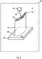
- Fig. 1 and Fig. 2 show individual process steps of a method according to the invention for producing a blade 10 for a turbomachine.
- the blade 10 is completely in Fig. 3 shown.
- Fig. 1 shows an additive construction of a blade 12 of the blade 10 on a present polycrystalline body 14.
- the base 14 may also be monocrystalline and / or directionally solidified.
- the generative building is carried out here by electron beam melting or selective laser sintering, wherein a present as a metallic powder, the first material 18 is sintered by an electron beam or laser beam 32.
- the electron / laser beam 32 is emitted by an electron beam gun or a laser 30.
- the blade 12 is thereby constructed on a support surface 16 of the base body 14.
- the main body 14 is presently designed as a beta-TiAl crystal plate.
- a separation of the blade 12 from the support surface 16 of the base 14 at a separation surface 20 of the blade 12 is not shown here separating the blade 12 from the support surface 16 of the body 14 preferably by erosion. This represents a particularly gentle separation process, as a result of which the main body 14 can be used to construct further airfoils.
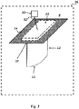
- Fig. 2 shows a further process step in which a generative construction of a blade root 22 of the blade 10 on the parting surface 20 of the blade 12 and thereby connecting the blade root 22 with the blade 12 takes place.
- the blade 12 is in a compared to Fig. 1 inverted position, so that a blade tip 13 now in Fig. 2 is directed downward in the drawing plane. Accordingly, the separation surface 20 is directed upward.
- the parting surface 20 is covered with a metallic powder of a second material 24.
- the blade root 22 is constructed by layer-sintering the powder of the second material 24 by means of the electron beam / laser beam 32.
- the two materials 18, 24 are different from each other.
- the first material 18 is formed as a TiAl alloy which, in addition to Ti and Al, comprises molybdenum as a further alloy constituent.
- niobium and molybdenum may also be included as further alloying constituents.
- the TiAl alloy may also comprise other or more elements from the group consisting of Mo, W, Zr, V, Y, Hf, Si, C and Co in order to adjust any material properties of the airfoil 22 as accurately as possible.
- a ⁇ -TiAl alloy is provided herein.
- This release of the composition is the nomenclature customary in the art where Ti is balance and accounts for the balance of 100 at.% Or, apart from unavoidable impurities, accounts for the balance of 100 at.%.
- the blade root 22 and the blade 12 are subjected after joining a - not shown here - common hot-isostatic pressing and an adjoining joint aging annealing.
- the described method is present completely in an in Fig. 1 and Fig. 2 Dashed construction chamber 26 performed, wherein the build-up chamber 26 is acted upon during the implementation of the method with a negative pressure P. Accordingly, in addition to the generative production of the airfoil 12 on the base body 14, the separation of the base body 14 from the airfoil 12 and the generative build-up of the blade root 22 on the airfoil 12 in the pressurized with the vacuum P build-up chamber 26 is performed. This has the advantage that any oxidation processes during the entire production of the blade can be at least largely excluded. Due to the negative pressure P, any oxidation processes during the process can at least be alleviated.
- Fig. 3 shows the blade 10 after its production.
- the blade 10 can now be joined to the blade root 22, for example with a rotor main body not shown here.
- a plug connection between the blade root 22 and the rotor base body can be produced.
- the method is based on the finding that ⁇ -TiAl alloys solidifying over a beta phase have the same crystal orientation from their melting temperature to room temperature.
- the main body 14 can be provided by making it by a drawing and separation method in a suitable oven (for example, in a Bridgman oven).
- a directional solidification of the crystals due to a controlled temperature gradient and crystal separator can be achieved.
- a directionally solidified monocrystalline or polycrystalline beta-TiAl crystal or crystallite block can be grown as the main body 14.
Landscapes
- Engineering & Computer Science (AREA)
- Chemical & Material Sciences (AREA)
- Mechanical Engineering (AREA)
- Materials Engineering (AREA)
- Physics & Mathematics (AREA)
- Manufacturing & Machinery (AREA)
- Optics & Photonics (AREA)
- Plasma & Fusion (AREA)
- Metallurgy (AREA)
- Organic Chemistry (AREA)
- Crystallography & Structural Chemistry (AREA)
- Thermal Sciences (AREA)
- Composite Materials (AREA)
- Ceramic Engineering (AREA)
- General Engineering & Computer Science (AREA)
- Structural Engineering (AREA)
- Civil Engineering (AREA)
- Inorganic Chemistry (AREA)
- Turbine Rotor Nozzle Sealing (AREA)
Abstract
- Bereitstellen eines ein- oder polykristallinen Grundkörpers (14) mit einer Auflagefläche (16) und generatives Aufbauen eines Schaufelblatts (12) der Schaufel (10) auf der Auflagefläche (16) durch schichtweises Verschmelzen und/oder Versintern eines metallischen und/oder keramischen Pulvers aus einem ersten Werkstoff (18) oder Werkstoffgemisch; und
- Abtrennen des Schaufelblatts (12) von der Auflagefläche (16) des Grundkörpers (14) an einer Trennfläche (20) des Schaufelblatts (12).
Description
- Die Erfindung betrifft ein Verfahren zum Herstellen einer Schaufel für eine Strömungsmaschine, insbesondere für ein Flugtriebwerk. Ein weiterer Aspekt der Erfindung betrifft eine derartige Schaufel welche durch ein entsprechendes Verfahren erhältlich und/oder erhalten ist.
- Bei der Fertigung von Schaufeln für Strömungsmaschinen ist zur Gewährleistung einer hohen Ausfallsicherheit größte Sorgfalt geboten. Bei der Auslegung und Herstellung der Schaufeln liegt eine erhebliche Herausforderung darin, dass diese einerseits extremen mechanischen und thermischen Belastungen Stand halten sollen und andererseits ein möglichst hoher Wirkungsgrad beim Betrieb der Strömungsmaschine erreicht werden soll.
- Aus der
US 2011/0135952 A1 ist ein Verfahren zum vollständigen Aufbauen eines Bauteils aus einem metallischen Pulver bekannt. Der Aufbau erfolgt auf einem Keimkristall, so dass einer Bauteilstruktur des Bauteils bei der Herstellung eine Orientierung des Keimkristalls aufgeprägt werden kann. - Die Druckschrift
DE 10 2012 222 745 A1 beschreibt ein Gießverfahren, bei welchem eine einkristalline und einteilige Turbinenschaufel hergestellt wird. Die Turbinenschaufel ist dabei aus einem TiAl-Werkstoff gebildet, wobei nach dem Gießverfahren unterschiedliche Werkstoffstrukturen in verschiedenen Bereichen der Turbinenschaufel vorliegen. - Die
US 2014/0154088 A1 zeigt ein schichtweises Aufbauen einer Turbinenschaufel auf einem metallischen Basismaterial. Dadurch wird der Turbinenschaufel durch ein generatives Herstellverfahren eine Maserung des metallischen Basismaterial aufgeprägt. Das mit der Turbinenschaufel verbundene Basismaterial wird als einteiliges Bauteil einer Gasturbine verwendet. - Aufgabe der vorliegenden Erfindung ist es, ein Verfahren der eingangs genannten Art zu schaffen, welches eine besonders aufwandsarme Fertigung von Schaufeln zulässt. Eine weitere Aufgabe der Erfindung ist es, eine Schaufel bereitzustellen, bei welcher zumindest einzelne Komponenten der Schaufel besonders einfach herstellbar sind.
- Die Aufgaben werden erfindungsgemäß durch ein Verfahren mit den Merkmalen des Patentanspruchs 1 und eine Schaufel gemäß Patentanspruch 12 gelöst. Vorteilhafte Ausgestaltungen mit zweckmäßigen Weiterbildungen der Erfindung sind in den jeweiligen Unteransprüchen angegeben, wobei vorteilhafte Ausgestaltungen jedes Erfindungsaspekts als vorteilhafte Ausgestaltungen des jeweils anderen Erfindungsaspekts und umgekehrt anzusehen sind.
- Ein erster Aspekt der Erfindung betrifft ein Verfahren zum Herstellen einer Schaufel für eine Strömungsmaschine, insbesondere für ein Flugtriebwerk, umfassend zumindest folgende Schritte:
- Bereitstellen eines ein- oder polykristallinen Grundkörpers mit einer Auflagefläche und generatives Aufbauen eines Schaufelblatts der Schaufel auf der Auflagefläche durch schichtweises Verschmelzen und/oder Versintern eines metallischen und/oder keramischen Pulvers aus einem ersten Werkstoff oder Werkstoffgemisch; und
- Abtrennen des Schaufelblatts von der Auflagefläche des Grundkörpers an einer Trennfläche des Schaufelblatts.
- Das generative Aufbauen durch schichtweises Verschmelzen kann dabei insbesondere mit gerichteter Erstarrung erfolgen.
- Das metallische und/oder keramische Pulver, welches versintert wird, kann insbesondere auch ein intermetallisches Pulver umfassen oder aus einem solchen bestehen.
- Das Pulver kann insbesondere zu einem Poly- oder Singelkristall, vorzugsweise einem gerichteten Poly- oder Singelkristall, versintert werden.
- Der Grundkörper kann als TiAl-Startkeimplatte, und damit beispielsweise als einkristallin oder als polykristallin ausgebildete Beta-TiAl-Kristall-Platte bereitgestellt werden. Diese Platte kann gerichtet erstarrt sein und damit eine definierte Kristallorientierung aufweisen. Bei dem generativen Aufbauen kann beispielsweise ein Elektronenstrahlschmelzen, welches auch als EBM-Verfahren (Electron Beam Melting) bezeichnet werden kann und zusätzlich oder alternativ ein selektives Laserschmelzen, welches auch als SLM-Verfahren (Selective Laser Melting) bezeichnet werden kann, eingesetzt werden. Bei dem generativen Aufbauen kann beispielsweise aus einem Pulver des ersten Werkstoffs oder Werkstoffgemisches ein Pulverbett bereitgestellt und das Schaufelblatt direkt durch Verschmelzen oder Versintern des Pulvers auf der Auflagefläche des Grundkörpers aufgebaut werden. Dabei erfolgt eine gerichtete Erstarrung einer bei dem generativen Aufbauen aus dem Pulver gebildeten, flüssigen Schmelze. Beim Erstarren der Schmelze wird dabei beispielsweise eine Orientierung der Beta-Phase des Grundkörpers einer Werkstoffstruktur des Schaufelblatts bei dessen Herstellung aufgeprägt. Auch in dem Schaufelblatt wird dadurch eine derartige Beta-Phase erzeugt. Durch das Aufprägen der Orientierung der Beta-Phase des Grundkörpers kann als Werkstoffstruktur des Schaufelblatts ein stängelkristalliner Aufbau einer Beta-Kornstruktur hergestellt werden. Die Werkstoffstruktur kann dabei entlang einer Längsachse des Schaufelblatts ausgerichtet sein. Somit können einzelne stängelartige Kristalle in dem Schaufelblatt nach dem Erstarren parallel zu der Längsachse orientiert sein. Die entsprechende Orientierung wird dabei während des generativen Aufbauens gesteuert. Nachdem das Schaufelblatt fertig aufgebaut ist, wird dieses von dem Grundkörper getrennt. Das Schaufelblatt kann dann mit einem Schaufelfuß zu der Schaufel verbunden werden. Nach dem Trennen von dem Schaufelblatt kann der Grundkörper mit der entsprechenden Auflagefläche zur Herstellung weiterer Schaufelblätter verwendet werden, wodurch insgesamt eine besonders aufwandsarme Schaufelfertigung möglich ist. Unter "generativen Aufbauen" oder "generativen Verfahren" werden gemäß der vorliegenden Erfindung alle geeigneten additiven Herstellungs- und Aufbauverfahren verstanden.
- In einer vorteilhaften Ausgestaltung der Erfindung erfolgt das Abtrennen des Schaufelblatts von der Auflagefläche des Grundkörpers durch Erodieren. Dadurch ist ein besonders schonendes Trennen des Grundkörpers von dem Schaufelblatt möglich. Derselbe Grundkörper kann dadurch besonders häufig zur Herstellung weiterer Schaufelblätter verwendet werden.
- In einer weiteren vorteilhaften Ausgestaltung der Erfindung erfolgt ein generatives Aufbauen eines Schaufelfußes der Schaufel auf der Trennfläche des Schaufelblatts und dabei ein Verbinden des Schaufelfußes mit dem Schaufelblatt. Das generative Aufbauen des Schaufelfußes auf der Trennfläche kann ebenfalls durch EBM und zusätzlich oder alternativ durch SLM erfolgen. Beispielsweise kann das Schaufelblatt nach dem Trennen von dem Grundkörper umgedreht und demzufolge mit nach oben gerichteter Trennfläche in einem EBM/SLM- Pulverbett aus dem ersten oder einem zweiten Werkstoff oder Werkstoffgemisch positioniert werden. Der zweite Werkstoff oder das zweite Werkstoffgemisch kann aus einer im Vergleich zu dem ersten Werkstoff oder Werkstoffgemisch duktileren γ-TiAl-Legierung gebildet sein. Nach dem Positionieren des Schaufelblatts kann das Pulverbett (beispielsweise aus dem γ-TiAl-Legierung) zudem aufgeheizt und darauf der Schaufelfuß mit einer erwünschten Struktur aufgebaut werden. Somit können auf einfache Weise unterschiedliche Strukturen im Schaufelblatt und im Schaufelfuß erzeugt werden.
- In einer weiteren vorteilhaften Ausgestaltung der Erfindung wird der Schaufelfuß bei dem generativen Aufbauen durch schichtweises Verschmelzen und/oder Versintern eines metallischen und/oder keramischen Pulvers aus dem zweiten Werkstoff oder Werkstoffgemisch, welcher/welches von dem ersten Werkstoff oder Werkstoffgemisch verschieden ist, hergestellt. Dadurch in dem Schaufelfuß und in dem Schaufelblatt besonders einfach unterschiedliche Werkstoffeigenschaften eingestellt werden.
- In einer weiteren vorteilhaften Ausgestaltung der Erfindung wird das generative Aufbauen des Schaufelfußes derart erzeugt, dass eine polykristalline Struktur in diesem hergestellt wird. Durch das Herstellen einer polykristallinen Struktur weist der Schaufelfuß eine besonders hohe Duktilität auf.
- In einer weiteren vorteilhaften Ausgestaltung der Erfindung erfolgt das generative Aufbauen des Schaufelblatts und/oder des Schaufelfußes in einer mit einem Unterdruck beaufschlagten Aufbaukammer. Durch das Beaufschlagen der Aufbaukammer mit Unterdruck kann eine besonders effektive Verdichtung des Pulvers beim Aufbau des Schaufelblatts erfolgen und letzteres somit mit einem besonders geringen Porenanteil und entsprechend großer Stabilität hergestellt werden. Des Weiteren trägt ein geringer Luftanteil infolge der Unterdruckumgebung dazu bei, dass etwaige, unerwünschte Oxidationsprozesse des Pulvers bei dessen schichtweisem Verschmelzen und/oder Versintern durch das generative Aufbauen weniger stark ausgeprägt sind, als dies unter atmosphärischem Luftdruck und entsprechend größeren Luftanteilen im Pulver der Fall wäre.
- In einer weiteren vorteilhaften Ausgestaltung der Erfindung werden der Schaufelfuß und das Schaufelblatt nach dem Verbinden einem gemeinsamen heiß-isostatischen Pressen unterzogen. Bei diesem heiß-isostatischen Pressen, welches auch als "HIP" abgekürzt werden kann, wird eine Mikrostruktur im beispielsweise aus TNM-TiAl hergestellten Schaufelfuß in eine sogenannte Triplex-Mikrostruktur mit hohem globularem Gamma-Anteil umgewandelt, wodurch beispielsweise eine gute Zerspanbarkeit des Schaufelfußes erreicht werden kann. Im Anschluss an das HIP kann eine Endbearbeitung der Schaufel, beispielsweise in Form einer Endkonturbearbeitung erfolgen.
- In einer weiteren vorteilhaften Ausgestaltung der Erfindung werden der Schaufelfuß und das Schaufelblatt nach dem Verbinden einem gemeinsamen Auslagerungsglühen unterzogen. Durch das Auslagerungsglühen können netzartige Omega-Ausscheidungen in der gerichtet erstarrten Beta-Phase des Schaufelblatts erzeugt werden. Dadurch kann das Schaufelblatt besonders stabil ausgebildet werden. Durch diese Wärmebehandlung (Auslagerungsglühen) werden in dem Schaufelblatt gerichtete, netzartige Mikrostrukturen eingestellt, mittels welchen besonders hohe Anforderungen an eine Kriechfestigkeit der Schaufel erfüllt werden können.
- In einer weiteren vorteilhaften Ausgestaltung der Erfindung wird als der erste Werkstoff eine TiAl-Legierung, insbesondere eine TiAl-Legierung, welche neben Ti und Al als weiteren Legierungsbestandteil wenigstens ein Element aus der Gruppe Nb, Mo, W, Zr, V, Y, Hf, Si, C und Co umfasst, bereitgestellt. Durch diese Legierungsbestandteile kann eine besonders gezielte Einstellung von Bauteileigenschaften erreicht werden. Somit sind diese Legierungen besonders geeignet um die Bauteileigenschaften beispielsweise des Schaufelblatts einzustellen.
- In einer weiteren vorteilhaften Ausgestaltung der Erfindung umfasst die TiAl-Legierung 30 bis 42 at.% Al, 5 bis 25 at.% Nb, 2 bis 10 at.% Mo, 0,1 bis 10 at.% Co, 0,1 bis 0,5 at.% Si, 0,1 bis 0,5 at.% Hf und Rest Ti, insbesondere 30 bis 35 at.% Al, 15 bis 25 at.% Nb, 5 bis 10 at.% Mo, 5 bis 10 at.% Co, 0,1 bis 0,5 at.% Si, 0,1 bis 0,5 at.% Hf und Rest Ti. Eine TiAl-Legierung mit einer derartigen Zusammensetzung ist besonders für den Einsatz als Schaufelmaterial geeignet.
- In einer weiteren vorteilhaften Ausgestaltung der Erfindung umfasst die TiAl-Legierung 30 bis 42 at.% Al, 5 bis 25 at.% Nb, 2 bis 10 at.% Mo, 0,1 bis 10 at.% Zr, 0,1 bis 1,5 at.% Si, 0,1 bis 0,5 at.% Hf und Rest Ti, insbesondere 32 bis 37 at.% Al, 15 bis 25 at.% Nb, 5 bis 10 at.% Mo, 1 bis 10 at.% Zr, 0,2 bis 1,0 at.% Si, 0,1 bis 0,5 at.% Hf und Rest Ti. Eine TiAl-Legierung mit einer derartigen Zusammensetzung ist ebenfalls besonders für den Einsatz als Schaufelmaterial geeignet.
- Insbesondere können TiAl-Legierungen nach den in der Druckschrift
EP 2 905 350 A1 beschriebenen Zusammensetzungen verwendet werden, aus welchen beispielsweise besonders stabile Schaufelblätter gebildet werden können. - In einer weiteren vorteilhaften Ausgestaltung der Erfindung wird als der zweite Werkstoff eine TiAl-Legierung, insbesondere eine γ-TiAl-Legierung, bereitgestellt. Eine derartige γ-TiAl-Legierung, welche auch als TNM-TiAl bezeichnet werden kann weist eine besonders hohe Warmfestigkeit bei gleichzeitig geringer Dichte auf. Somit ist γ-TiAl besonders für den Einsatz in Flugtriebwerken, also beispielsweise als Werkstoff für den Schaufelfuß, geeignet.
- Ein zweiter Aspekt der Erfindung betrifft eine Schaufel für eine Strömungsmaschine, insbesondere für ein Flugtriebwerk, welche durch ein erfindungsgemäßes Verfahren erhältlich und/oder erhalten ist. Eine derartige Schaufel kann besonders einfach hergestellt werden. Weitere Merkmale und deren Vorteile sind den Beschreibungen des ersten Erfindungsaspekts zu entnehmen, wobei vorteilhafte Ausgestaltungen des ersten Erfindungsaspekts als vorteilhafte Ausgestaltungen des zweiten Erfindungsaspekts und umgekehrt anzusehen sind.
- Weitere Merkmale der Erfindung ergeben sich aus den Ansprüchen, den Ausführungsbeispielen sowie anhand der Zeichnung. Die vorstehend in der Beschreibung genannten Merkmale und Merkmalskombinationen, sowie die nachfolgend in den Ausführungsbeispielen genannten und/oder alleine beschriebenen Merkmale und Merkmalskombinationen sind nicht nur in der jeweils angegebenen Kombination, sondern auch in anderen Kombinationen oder in Alleinstellung verwendbar, ohne den Rahmen der Erfindung zu verlassen. Es sind somit auch Ausführungen von der Erfindung als umfasst und offenbart anzusehen, die in den Ausführungsbeispielen nicht explizit gezeigt und erläutert sind, jedoch durch separierte Merkmalskombinationen aus den erläuterten Ausführungen hervorgehen und erzeugbar sind. Es sind auch Ausführungen und Merkmalskombinationen als offenbart anzusehen, die somit nicht alle Merkmale eines ursprünglich formulierten unabhängigen Anspruchs aufweisen. Dabei zeigt:
- Fig. 1
- eine schematische Perspektivansicht auf ein Schaufelblatt einer erfindungsgemäßen Schaufel, wobei das Schaufelblatt generativ auf einem Grundkörper aufgebaut wird;
- Fig. 2
- eine schematische Perspektivansicht auf einen Schaufelfuß der erfindungsgemäßen Schaufel, wobei der Schaufelfuß generativ auf einer Trennfläche des Schaufelblatts aufgebaut wird; und
- Fig. 3
- eine schematische Perspektivansicht auf die erfindungsgemäße Schaufel.
-
Fig. 1 undFig. 2 zeigen einzelne Verfahrensschritte eines erfindungsgemäßen Verfahrens zur Herstellung einer Schaufel 10 für eine Strömungsmaschine. Die Schaufel 10 ist dabei vollständig inFig. 3 gezeigt. -
Fig. 1 zeigt ein generatives Aufbauen eines Schaufelblatts 12 der Schaufel 10 auf einem vorliegend polykristallinen Grundkörper 14. Alternativ oder zusätzlich kann der Grundkörper 14 auch einkristallin und/oder gerichtet erstarrt sein. Das generative Aufbauen erfolgt hierbei durch Elektronenstrahlschmelzen oder selektives Lasersintern, wobei ein als metallisches Pulver vorliegender, erster Werkstoff 18 durch einen Elektronenstrahl oder Laserstrahl 32 gesintert wird. Der Elektronen-/ Laserstrahl 32 wird durch eine Elektronenstrahlkanone oder einen Laser 30 emittiert. Das Schaufelblatt 12 wird dabei auf einer Auflagefläche 16 des Grundkörpers 14 aufgebaut. Der Grundkörper 14 ist vorliegend als Beta-TiAl-Kristall-Platte ausgebildet. Durch das generative Aufbauen des Schaufelblatts 12 auf dem ein- oder polykristallinen, vorzugsweise gerichtet erstarrten, Grundkörper 14 kann eine Orientierung einer Beta-Phase des Grundkörpers 14 einer Werkstoffstruktur des Schaufelblatts 12 bei dessen Herstellung aufgeprägt werden. - Im Anschluss an das Aufbauen des Schaufelblatts 12 erfolgt ein hier nicht dargestelltes Abtrennen des Schaufelblatts 12 von der Auflagefläche 16 des Grundkörpers 14 an einer Trennfläche 20 des Schaufelblatts 12. Das Abtrennen des Schaufelblatts 12 von der Auflagefläche 16 des Grundkörpers 14 erfolgt dabei vorzugsweise durch Erodieren. Dies stellt ein besonders schonendes Trennverfahren dar, wodurch der Grundkörper 14 zum Aufbau weiterer Schaufelblätter verwendet werden kann.
-
Fig. 2 zeigt einen weiteren Verfahrensschritt, in welchem ein generatives Aufbauen eines Schaufelfußes 22 der Schaufel 10 auf der Trennfläche 20 des Schaufelblatts 12 und dabei ein Verbinden des Schaufelfußes 22 mit dem Schaufelblatt 12 erfolgt. Hierzu befindet sich das Schaufelblatt 12 in einer im Vergleich zuFig. 1 umgedrehten Lage, so dass eine Schaufelspitze 13 nunmehr inFig. 2 in der Zeichenebene nach unten gerichtet ist. Dementsprechend ist die Trennfläche 20 nach oben gerichtet. Die Trennfläche 20 ist mit einem metallischen Pulver eines zweiten Werkstoffs 24 bedeckt. Der Schaufelfuß 22 wird durch schichtweises Versintern des Pulvers des zweiten Werkstoffs 24 mittels des Elektronenstrahls / Laserstrahls 32 aufgebaut. Die beiden Werkstoffe 18, 24 sind dabei voneinander verschieden. - Der erste Werkstoff 18 ist vorliegend als eine TiAl-Legierung ausgebildet, welche neben Ti und Al als weiteren Legierungsbestandteil Molybdän umfasst. Alternativ, können neben Ti und Al auch Niob und Molybdän als weitere Legierungsbestandteile umfasst sein. Die TiAl-Legierung kann auch andere oder mehrere Elemente aus der Gruppe Mo, W, Zr, V, Y, Hf, Si, C und Co umfassen, um etwaige Werkstoffeigenschaften des Schaufelblatts 22 möglichst exakt einzustellen. Als der zweite Werkstoff 24 wird vorliegend eine γ-TiAl-Legierung bereitgestellt.
- In manchen Ausführungsformen kann die γ-TiAl-Legierung mit der Zusammensetzung TNM Ti 41-44Al2-5Nb 0,5-2Mo 0,01-0,5B optional + 0,2-0,5Si 0,2-0,5C [at.%] bereitgestellt werden. Bei dieser Abgabe der Zusammensetzung handelt es sich um die auf dem Fachgebiet übliche Nomenklatur, bei der Ti Balance ist und den Rest von 100 at.% ausmacht oder - abgesehen von unvermeidbaren Verunreinigungen - den Rest von 100 at.% ausmacht.
Der Schaufelfuß 22 und das Schaufelblatt 12 werden nach dem Verbinden einem - hier hier nicht weiter gezeigten - gemeinsamen heiß-isostatischen Pressen sowie einem daran anschließenden gemeinsamen Auslagerungsglühen unterzogen. - Das beschriebene Verfahren wird vorliegend vollständig in einer in
Fig. 1 undFig. 2 gestrichelt dargestellten Aufbaukammer 26 durchgeführt, wobei die Aufbaukammer 26 während der Durchführung des Verfahrens mit einem Unterdruck P beaufschlagt ist. Demzufolge wird neben dem generativen Herstellen des Schaufelblatts 12 auf dem Grundkörper 14 auch das Trennen des Grundkörpers 14 von dem Schaufelblatt 12 sowie das generative Aufbauen des Schaufelfußes 22 auf dem Schaufelblatt 12 in der mit dem Unterdruck P beaufschlagen Aufbaukammer 26 durchgeführt. Dies hat den Vorteil, dass etwaige Oxidationsprozesse während der gesamten Herstellung der Schaufel zumindest weitgehend ausgeschlossen werden können. Durch den Unterdruck P können etwaige Oxidationsprozesse während des Verfahrens zumindest abgeschwächt werden. -
Fig. 3 zeigt die Schaufel 10 nach deren Herstellung. Die Schaufel 10 kann nun an dem Schaufelfuß 22 beispielsweise mit einem hier nicht weiter dargestellten Rotorgrundkörper gefügt werden. Beim Fügen kann beispielsweise eine Steckverbindung zwischen dem Schaufelfuß 22 und dem Rotorgrundkörper hergestellt werden. - Dem Verfahren liegt die Erkenntnis zugrunde, dass über eine Beta-Phase erstarrende Beta-TiAl-Legierungen von deren Schmelztemperatur bis zur Raumtemperatur eine gleiche Kristallorientierung aufweisen. Dadurch kann der Grundkörpers 14 bereitgestellt werden, indem dieser durch ein Zieh- und Separationsverfahren in einem geeigneten Ofen (beispielsweise in einem Bridgman-Ofen) hergestellt wird. Hierbei kann eine gerichtete Erstarrung der Kristalle aufgrund eines gesteuerten Temperaturgradienten und Kristall-Separators erreicht werden. Dadurch kann als der Grundkörper 14 ein gerichtet erstarrter ein- oder polykristalliner Beta-TiAl-Kristall- bzw. Kristallit-Block gezüchtet werden.
-
- 10
- Schaufel
- 12
- Schaufelblatt
- 13
- Schaufelspitze
- 14
- Grundkörper
- 16
- Auflagefläche
- 18
- erster Werkstoff
- 20
- Trennfläche
- 22
- Schaufelfuß
- 24
- zweiter Werkstoff
- 26
- Aufbaukammer
- 30
- Elektronenstrahlkanone / Laser
- 32
- Elektronenstrahl oder Laserstrahl
Claims (12)
- Verfahren zum Herstellen einer Schaufel (10) für eine Strömungsmaschine, insbesondere für ein Flugtriebwerk, umfassend zumindest folgende Schritte:- Bereitstellen eines ein- oder polykristallinen Grundkörpers (14) mit einer Auflagefläche (16) und generatives Aufbauen eines Schaufelblatts (12) der Schaufel (10) auf der Auflagefläche (16) durch schichtweises Verschmelzen und/oder Versintern eines metallischen und/oder keramischen Pulvers aus einem ersten Werkstoff (18) oder Werkstoffgemisch; und- Abtrennen des Schaufelblatts (12) von der Auflagefläche (16) des Grundkörpers (14) an einer Trennfläche (20) des Schaufelblatts (12).
- Verfahren nach einem der vorhergehenden Ansprüche,
dadurch gekennzeichnet, dass
das Abtrennen des Schaufelblatts (12) von der Auflagefläche (16) des Grundkörpers (14) durch Erodieren erfolgt. - Verfahren nach Anspruch 1 oder 2,
dadurch gekennzeichnet, dass
ein generatives Aufbauen eines Schaufelfußes (22) der Schaufel (10) auf der Trennfläche (20) des Schaufelblatts (12) und dabei ein Verbinden des Schaufelfußes (22) mit dem Schaufelblatt (12) erfolgt. - Verfahren nach Anspruch 3,
dadurch gekennzeichnet, dass
der Schaufelfuß (22) bei dem generativen Aufbauen durch schichtweises Verschmelzen und/oder Versintern eines metallischen und/oder keramischen Pulvers aus einem zweiten Werkstoff (24) oder Werkstoffgemisch, welcher/welches von dem ersten Werkstoff (18) oder Werkstoffgemisch verschieden ist, hergestellt wird. - Verfahren nach Anspruch 3 oder 4,
dadurch gekennzeichnet, dass
das generative Aufbauen des Schaufelfußes (22) derart durchgeführt wird, dass eine polykristalline Struktur in diesem hergestellt wird. - Verfahren nach Anspruch einem der Ansprüche 3 bis 5,
dadurch gekennzeichnet, dass
das generative Aufbauen des Schaufelblatts (12) und/oder des Schaufelfußes (22) in einer mit einem Unterdruck (P) beaufschlagten Aufbaukammer (26) erfolgt. - Verfahren nach einem der Ansprüche 3 bis 6,
dadurch gekennzeichnet, dass
der Schaufelfuß (22) und das Schaufelblatt (12) nach dem Verbinden einem gemeinsamen heiß-isostatischen Pressen unterzogen werden. - Verfahren nach einem der Ansprüche 3 bis 7,
dadurch gekennzeichnet, dass
der Schaufelfuß (22) und das Schaufelblatt (12) nach dem Verbinden einem gemeinsamen Auslagerungsglühen unterzogen werden. - Verfahren nach einem der vorhergehenden Ansprüche,
dadurch gekennzeichnet, dass
als der erste Werkstoff (18) eine TiAl-Legierung, insbesondere eine TiAl-Legierung, welche neben Ti und Al als weiteren Legierungsbestandteil wenigstens ein Element aus der Gruppe Nb, Mo, W, Zr, V, Y, Hf, Si, C und Co umfasst, bereitgestellt wird. - Verfahren nach Anspruch 9,
dadurch gekennzeichnet, dass
die TiAl-Legierung- 30 bis 42 at.% Al- 5 bis 25 at.% Nb- 2 bis 10 at.% Mo- 0,1 bis 10 at.% Co oder Zr- 0,1 bis 1,5 at.% Si, insbesondere 0,1 bis 0,5 at.% Si,- 0,1 bis 0,5 at.% Hf und Rest Ti,insbesondere- 30 bis 35 at.% Al oder 32 bis 37 at.% Al- 15 bis 25 at.% Nb- 5 bis 10 at.% Mo- 1 bis 10 at.% Co oder Zr, insbesondere 5 bis 10 at.% Co oder Zr- 0,1 bis 0,5 at.% Si oder 0,2 bis 1,0 at.% Si- 0,1 bis 0,5 at.% Hf und Rest Ti, umfasst. - Verfahren nach einem der Ansprüche 4 bis 10,
dadurch gekennzeichnet, dass
als der zweite Werkstoff (24) eine TiAl-Legierung, insbesondere eine γ-TiAl-Legierung, bereitgestellt wird. - Schaufel (10) für eine Strömungsmaschine, insbesondere für ein Flugtriebwerk, welche durch ein Verfahren nach einem der Ansprüche 1 bis 11 erhältlich und/oder erhalten ist.
Applications Claiming Priority (1)
| Application Number | Priority Date | Filing Date | Title |
|---|---|---|---|
| DE102016203785.4A DE102016203785A1 (de) | 2016-03-08 | 2016-03-08 | Verfahren zum Herstellen einer Schaufel für eine Strömungsmaschine |
Publications (2)
| Publication Number | Publication Date |
|---|---|
| EP3216547A1 true EP3216547A1 (de) | 2017-09-13 |
| EP3216547B1 EP3216547B1 (de) | 2021-06-23 |
Family
ID=58266395
Family Applications (1)
| Application Number | Title | Priority Date | Filing Date |
|---|---|---|---|
| EP17159757.8A Active EP3216547B1 (de) | 2016-03-08 | 2017-03-08 | Verfahren zum herstellen einer schaufel für eine strömungsmaschine |
Country Status (3)
| Country | Link |
|---|---|
| US (1) | US20170260865A1 (de) |
| EP (1) | EP3216547B1 (de) |
| DE (1) | DE102016203785A1 (de) |
Cited By (4)
| Publication number | Priority date | Publication date | Assignee | Title |
|---|---|---|---|---|
| EP3530763A1 (de) * | 2018-02-22 | 2019-08-28 | MTU Aero Engines GmbH | Verfahren zur herstellung eines bauteils aus einer gradierten tial - legierung und entsprechend hergestelltes bauteil |
| CN110295301A (zh) * | 2019-07-09 | 2019-10-01 | 中国兵器科学研究院宁波分院 | 一种钨钛合金的制备方法 |
| CN112030053A (zh) * | 2020-09-02 | 2020-12-04 | 中国航发北京航空材料研究院 | 一种高温环境应用的轻质多主元合金 |
| WO2024006641A1 (en) * | 2022-06-27 | 2024-01-04 | The Boeing Company | Multi-material structures and methods |
Families Citing this family (8)
| Publication number | Priority date | Publication date | Assignee | Title |
|---|---|---|---|---|
| US10737325B2 (en) * | 2016-09-06 | 2020-08-11 | David Money | Additive printing method |
| EP3326746A1 (de) * | 2016-11-25 | 2018-05-30 | Helmholtz-Zentrum Geesthacht Zentrum für Material- und Küstenforschung GmbH | Verfahren zum fügen und/oder reparieren von substraten aus titanaluminidlegierungen |
| US20190040749A1 (en) * | 2017-08-01 | 2019-02-07 | United Technologies Corporation | Method of fabricating a turbine blade |
| JP7024328B2 (ja) * | 2017-10-31 | 2022-02-24 | 株式会社Ihi | 金属部材の作製方法 |
| US20190338650A1 (en) * | 2018-05-07 | 2019-11-07 | Rolls-Royce Corporation | Turbine blade squealer tip including internal squealer tip cooling channel |
| US11167375B2 (en) | 2018-08-10 | 2021-11-09 | The Research Foundation For The State University Of New York | Additive manufacturing processes and additively manufactured products |
| DE102019200620A1 (de) * | 2019-01-18 | 2020-07-23 | MTU Aero Engines AG | Verfahren zur Herstellung von Laufschaufeln aus Ni-Basislegierungen und entsprechend hergestellte Laufschaufel |
| ES2900049A1 (es) * | 2020-09-15 | 2022-03-15 | Baikor Worldwide S L | Metodo de fabricacion de un componente metalico |
Citations (8)
| Publication number | Priority date | Publication date | Assignee | Title |
|---|---|---|---|---|
| US20110135952A1 (en) | 2009-12-04 | 2011-06-09 | Honeywell International Inc. | Turbine components for engines and methods of fabricating the same |
| EP2620594A1 (de) * | 2012-01-27 | 2013-07-31 | Honeywell International Inc. | Turbinenkomponenten aus mehreren Materialien |
| US20140154088A1 (en) | 2012-12-01 | 2014-06-05 | Alstom Technology Ltd. | Method for manufacturing a metallic component by additive laser manufacturing |
| DE102012222745A1 (de) | 2012-12-11 | 2014-06-12 | MTU Aero Engines AG | Einkristalline Turbinenschaufel aus Titanaluminid |
| EP2772329A1 (de) * | 2013-02-28 | 2014-09-03 | Alstom Technology Ltd | Verfahren zur Herstellung einer Hybridkomponente |
| WO2014172496A1 (en) * | 2013-04-19 | 2014-10-23 | United Technologies Corporation | Build plate and apparatus for additive manufacturing |
| WO2015109102A1 (en) * | 2014-01-20 | 2015-07-23 | United Technologies Corporation | An additive manufacturing system utilizing an epitaxy process and method of operation |
| EP2905350A1 (de) | 2014-02-06 | 2015-08-12 | MTU Aero Engines GmbH | Hochtemperatur TiAl-Legierung |
Family Cites Families (7)
| Publication number | Priority date | Publication date | Assignee | Title |
|---|---|---|---|---|
| DE102006049216A1 (de) * | 2006-10-18 | 2008-04-24 | Mtu Aero Engines Gmbh | Hochdruckturbinen-Rotor und Verfahren zur Herstellung eines Hochdruckturbinen-Rotors |
| DE102009049707A1 (de) * | 2009-10-17 | 2011-07-28 | MTU Aero Engines GmbH, 80995 | Verfahren zur Herstellung einer Lauf- oder Statorschaufel und eine derartige Schaufel |
| DE102013220467A1 (de) * | 2013-10-10 | 2015-05-07 | MTU Aero Engines AG | Rotor mit einem Rotorgrundkörper und einer Mehrzahl daran angebrachter Laufschaufeln |
| DE102014206827A1 (de) * | 2014-04-09 | 2015-10-15 | Siemens Aktiengesellschaft | Verfahren zum Fügen und Gasturbinenkomponente |
| DE102014009735B4 (de) * | 2014-07-02 | 2021-07-15 | Rosswag Gmbh | Laufrad einer Strömungsmaschine |
| DE102014012480B4 (de) * | 2014-08-27 | 2016-06-09 | Rosswag Gmbh | Herstellverfahren für eine Beschaufelung einer Strömungsmaschine, Beschaufelung einer Strömungsmaschine und Laufrad |
| DE102014226013A1 (de) * | 2014-12-16 | 2016-06-16 | Siemens Aktiengesellschaft | Verfahren zur generativen Fertigung eines Werkstücks |
-
2016
- 2016-03-08 DE DE102016203785.4A patent/DE102016203785A1/de not_active Withdrawn
-
2017
- 2017-03-07 US US15/451,529 patent/US20170260865A1/en not_active Abandoned
- 2017-03-08 EP EP17159757.8A patent/EP3216547B1/de active Active
Patent Citations (8)
| Publication number | Priority date | Publication date | Assignee | Title |
|---|---|---|---|---|
| US20110135952A1 (en) | 2009-12-04 | 2011-06-09 | Honeywell International Inc. | Turbine components for engines and methods of fabricating the same |
| EP2620594A1 (de) * | 2012-01-27 | 2013-07-31 | Honeywell International Inc. | Turbinenkomponenten aus mehreren Materialien |
| US20140154088A1 (en) | 2012-12-01 | 2014-06-05 | Alstom Technology Ltd. | Method for manufacturing a metallic component by additive laser manufacturing |
| DE102012222745A1 (de) | 2012-12-11 | 2014-06-12 | MTU Aero Engines AG | Einkristalline Turbinenschaufel aus Titanaluminid |
| EP2772329A1 (de) * | 2013-02-28 | 2014-09-03 | Alstom Technology Ltd | Verfahren zur Herstellung einer Hybridkomponente |
| WO2014172496A1 (en) * | 2013-04-19 | 2014-10-23 | United Technologies Corporation | Build plate and apparatus for additive manufacturing |
| WO2015109102A1 (en) * | 2014-01-20 | 2015-07-23 | United Technologies Corporation | An additive manufacturing system utilizing an epitaxy process and method of operation |
| EP2905350A1 (de) | 2014-02-06 | 2015-08-12 | MTU Aero Engines GmbH | Hochtemperatur TiAl-Legierung |
Cited By (4)
| Publication number | Priority date | Publication date | Assignee | Title |
|---|---|---|---|---|
| EP3530763A1 (de) * | 2018-02-22 | 2019-08-28 | MTU Aero Engines GmbH | Verfahren zur herstellung eines bauteils aus einer gradierten tial - legierung und entsprechend hergestelltes bauteil |
| CN110295301A (zh) * | 2019-07-09 | 2019-10-01 | 中国兵器科学研究院宁波分院 | 一种钨钛合金的制备方法 |
| CN112030053A (zh) * | 2020-09-02 | 2020-12-04 | 中国航发北京航空材料研究院 | 一种高温环境应用的轻质多主元合金 |
| WO2024006641A1 (en) * | 2022-06-27 | 2024-01-04 | The Boeing Company | Multi-material structures and methods |
Also Published As
| Publication number | Publication date |
|---|---|
| EP3216547B1 (de) | 2021-06-23 |
| DE102016203785A1 (de) | 2017-09-14 |
| US20170260865A1 (en) | 2017-09-14 |
Similar Documents
| Publication | Publication Date | Title |
|---|---|---|
| EP3216547B1 (de) | Verfahren zum herstellen einer schaufel für eine strömungsmaschine | |
| EP2548685B2 (de) | Lot zum Hochtemperaturlöten und Verfahren zum Reparieren bzw. Herstellen von Bauteilen unter Verwendung dieses Lotes | |
| EP3069803A1 (de) | Schaufel einer strömungsmaschine aus unterschiedlichen werkstoffen und verfahren zur herstellung derselben | |
| EP3170609A1 (de) | Verfahren zum herstellen eines beschaufelten rotors für eine strömungsmaschine ; entsprechender beschaufelter rotor | |
| EP2461936B1 (de) | Reparatur von turbinenbauteilen | |
| EP2548686B1 (de) | Lötfolie zum Hochtemperaturlöten und Verfahren zum Reparieren bzw. Herstellen von Bauteilen unter Verwendung dieser Lötfolie | |
| DE102006049216A1 (de) | Hochdruckturbinen-Rotor und Verfahren zur Herstellung eines Hochdruckturbinen-Rotors | |
| EP3468740B1 (de) | Verfahren zum fügen von werkstoffen durch verwendung einer mit einem additiven verfahren hergestellten gitterstruktur | |
| WO2007085230A1 (de) | Leitschaufelsegment einer gasturbine und verfahren zu dessen herstellung | |
| EP3249064A1 (de) | Additive fertigung von hochtemperaturbauteilen aus tial | |
| EP2807281B1 (de) | Verfahren zur herstellung geschmiedeter bauteile aus einer tial-legierung und entsprechend hergestelltes bauteil | |
| EP3238868A1 (de) | Verfahren zum herstellen einer schaufel für eine strömungsmaschine | |
| EP3530763B1 (de) | Verfahren zur herstellung einer schaufel einer strömungsmaschine aus einer gradierten tial-legierung und entsprechend hergestelltes bauteil | |
| EP3239468A1 (de) | Verfahren zum herstellen einer schaufel für eine strömungsmaschine | |
| EP3450056A1 (de) | Verfahren zur herstellung eines titanaluminid-bauteils mit zähem kern und entsprechend hergestelltes bauteil | |
| DE102018209315A1 (de) | Verfahren zur Herstellung eines Bauteils aus Gamma - TiAl und entsprechend hergestelltes Bauteil | |
| EP3269838A1 (de) | Hochwarmfeste tial-legierung und herstellungsverfahren hierfür sowie bauteil aus einer entsprechenden tial-legierung | |
| CH709882B1 (de) | Verfahren für das metallurgische Festzustandsverbinden verschiedener Hochtemperaturmaterialien und damit hergestellter Artikel. | |
| EP3682988A1 (de) | Verfahren zur herstellung von laufschaufeln aus ni - basislegierungen und entsprechend hergestellte laufschaufel | |
| EP3238863A1 (de) | Verfahren zum herstellen einer schaufel für eine strömungsmaschine | |
| DE102010034337A1 (de) | Verfahren zum Verbinden einer Turbinenschaufel mit einer Turbinenscheibe oder einem Turbinenring | |
| WO2013029584A1 (de) | Verfahren zum herstellen, reparieren und/oder austauschen eines rotor/stator-verbundsystems, sowie ein gemäss dem verfahren hergestelltes rotor/stator-verbundsystem | |
| DE102016223731A1 (de) | Verfahren zum Herstellen einer Schaufel für eine Strömungsmaschine | |
| DE10343782A1 (de) | Verfahren zur Herstellung von Bauteilen | |
| WO2022105967A1 (de) | Verfahren zur herstellung eines bauteils aus einer legierung und entsprechend hergestelltes bauteil |
Legal Events
| Date | Code | Title | Description |
|---|---|---|---|
| PUAI | Public reference made under article 153(3) epc to a published international application that has entered the european phase |
Free format text: ORIGINAL CODE: 0009012 |
|
| STAA | Information on the status of an ep patent application or granted ep patent |
Free format text: STATUS: THE APPLICATION HAS BEEN PUBLISHED |
|
| AK | Designated contracting states |
Kind code of ref document: A1 Designated state(s): AL AT BE BG CH CY CZ DE DK EE ES FI FR GB GR HR HU IE IS IT LI LT LU LV MC MK MT NL NO PL PT RO RS SE SI SK SM TR |
|
| AX | Request for extension of the european patent |
Extension state: BA ME |
|
| STAA | Information on the status of an ep patent application or granted ep patent |
Free format text: STATUS: REQUEST FOR EXAMINATION WAS MADE |
|
| 17P | Request for examination filed |
Effective date: 20180227 |
|
| RBV | Designated contracting states (corrected) |
Designated state(s): AL AT BE BG CH CY CZ DE DK EE ES FI FR GB GR HR HU IE IS IT LI LT LU LV MC MK MT NL NO PL PT RO RS SE SI SK SM TR |
|
| STAA | Information on the status of an ep patent application or granted ep patent |
Free format text: STATUS: EXAMINATION IS IN PROGRESS |
|
| 17Q | First examination report despatched |
Effective date: 20190313 |
|
| GRAP | Despatch of communication of intention to grant a patent |
Free format text: ORIGINAL CODE: EPIDOSNIGR1 |
|
| STAA | Information on the status of an ep patent application or granted ep patent |
Free format text: STATUS: GRANT OF PATENT IS INTENDED |
|
| RIC1 | Information provided on ipc code assigned before grant |
Ipc: B33Y 80/00 20150101ALI20200709BHEP Ipc: B23K 26/08 20140101ALI20200709BHEP Ipc: B23K 26/342 20140101ALI20200709BHEP Ipc: C22F 1/18 20060101ALI20200709BHEP Ipc: B22F 7/06 20060101ALI20200709BHEP Ipc: B22F 3/105 20060101AFI20200709BHEP Ipc: C22C 1/04 20060101ALN20200709BHEP Ipc: C22C 30/00 20060101ALI20200709BHEP Ipc: C22C 27/02 20060101ALI20200709BHEP Ipc: C30B 29/52 20060101ALI20200709BHEP Ipc: B23K 26/12 20140101ALI20200709BHEP Ipc: B33Y 10/00 20150101ALI20200709BHEP Ipc: C30B 13/22 20060101ALI20200709BHEP Ipc: B22F 5/04 20060101ALI20200709BHEP Ipc: B23K 15/06 20060101ALI20200709BHEP Ipc: B23P 15/04 20060101ALI20200709BHEP Ipc: B23K 101/00 20060101ALN20200709BHEP Ipc: B23K 26/00 20140101ALI20200709BHEP Ipc: F01D 5/28 20060101ALI20200709BHEP Ipc: C22C 14/00 20060101ALI20200709BHEP Ipc: B23K 15/00 20060101ALI20200709BHEP Ipc: B23K 103/14 20060101ALN20200709BHEP |
|
| INTG | Intention to grant announced |
Effective date: 20200804 |
|
| GRAJ | Information related to disapproval of communication of intention to grant by the applicant or resumption of examination proceedings by the epo deleted |
Free format text: ORIGINAL CODE: EPIDOSDIGR1 |
|
| STAA | Information on the status of an ep patent application or granted ep patent |
Free format text: STATUS: EXAMINATION IS IN PROGRESS |
|
| GRAP | Despatch of communication of intention to grant a patent |
Free format text: ORIGINAL CODE: EPIDOSNIGR1 |
|
| STAA | Information on the status of an ep patent application or granted ep patent |
Free format text: STATUS: GRANT OF PATENT IS INTENDED |
|
| INTC | Intention to grant announced (deleted) | ||
| RIC1 | Information provided on ipc code assigned before grant |
Ipc: B23K 101/00 20060101ALN20201204BHEP Ipc: B23P 15/04 20060101ALI20201204BHEP Ipc: B23K 15/00 20060101ALI20201204BHEP Ipc: B22F 5/04 20060101ALI20201204BHEP Ipc: C22C 27/02 20060101ALI20201204BHEP Ipc: B23K 15/06 20060101ALI20201204BHEP Ipc: B23K 26/12 20140101ALI20201204BHEP Ipc: B23K 26/342 20140101ALI20201204BHEP Ipc: C22F 1/18 20060101ALI20201204BHEP Ipc: C22C 30/00 20060101ALI20201204BHEP Ipc: B23K 103/14 20060101ALN20201204BHEP Ipc: B22F 3/105 20060101AFI20201204BHEP Ipc: C22C 1/04 20060101ALN20201204BHEP Ipc: C22C 14/00 20060101ALI20201204BHEP Ipc: B22F 7/06 20060101ALI20201204BHEP Ipc: B23K 26/00 20140101ALI20201204BHEP Ipc: F01D 5/28 20060101ALI20201204BHEP Ipc: B33Y 80/00 20150101ALI20201204BHEP Ipc: B23K 26/08 20140101ALI20201204BHEP Ipc: B33Y 10/00 20150101ALI20201204BHEP Ipc: C30B 13/22 20060101ALI20201204BHEP Ipc: C30B 29/52 20060101ALI20201204BHEP |
|
| INTG | Intention to grant announced |
Effective date: 20210113 |
|
| GRAS | Grant fee paid |
Free format text: ORIGINAL CODE: EPIDOSNIGR3 |
|
| GRAA | (expected) grant |
Free format text: ORIGINAL CODE: 0009210 |
|
| STAA | Information on the status of an ep patent application or granted ep patent |
Free format text: STATUS: THE PATENT HAS BEEN GRANTED |
|
| AK | Designated contracting states |
Kind code of ref document: B1 Designated state(s): AL AT BE BG CH CY CZ DE DK EE ES FI FR GB GR HR HU IE IS IT LI LT LU LV MC MK MT NL NO PL PT RO RS SE SI SK SM TR |
|
| REG | Reference to a national code |
Ref country code: GB Ref legal event code: FG4D Free format text: NOT ENGLISH |
|
| REG | Reference to a national code |
Ref country code: CH Ref legal event code: EP |
|
| REG | Reference to a national code |
Ref country code: DE Ref legal event code: R096 Ref document number: 502017010711 Country of ref document: DE Ref country code: AT Ref legal event code: REF Ref document number: 1403866 Country of ref document: AT Kind code of ref document: T Effective date: 20210715 |
|
| REG | Reference to a national code |
Ref country code: IE Ref legal event code: FG4D Free format text: LANGUAGE OF EP DOCUMENT: GERMAN |
|
| REG | Reference to a national code |
Ref country code: LT Ref legal event code: MG9D |
|
| PG25 | Lapsed in a contracting state [announced via postgrant information from national office to epo] |
Ref country code: HR Free format text: LAPSE BECAUSE OF FAILURE TO SUBMIT A TRANSLATION OF THE DESCRIPTION OR TO PAY THE FEE WITHIN THE PRESCRIBED TIME-LIMIT Effective date: 20210623 Ref country code: BG Free format text: LAPSE BECAUSE OF FAILURE TO SUBMIT A TRANSLATION OF THE DESCRIPTION OR TO PAY THE FEE WITHIN THE PRESCRIBED TIME-LIMIT Effective date: 20210923 Ref country code: FI Free format text: LAPSE BECAUSE OF FAILURE TO SUBMIT A TRANSLATION OF THE DESCRIPTION OR TO PAY THE FEE WITHIN THE PRESCRIBED TIME-LIMIT Effective date: 20210623 Ref country code: LT Free format text: LAPSE BECAUSE OF FAILURE TO SUBMIT A TRANSLATION OF THE DESCRIPTION OR TO PAY THE FEE WITHIN THE PRESCRIBED TIME-LIMIT Effective date: 20210623 |
|
| PG25 | Lapsed in a contracting state [announced via postgrant information from national office to epo] |
Ref country code: LV Free format text: LAPSE BECAUSE OF FAILURE TO SUBMIT A TRANSLATION OF THE DESCRIPTION OR TO PAY THE FEE WITHIN THE PRESCRIBED TIME-LIMIT Effective date: 20210623 Ref country code: GR Free format text: LAPSE BECAUSE OF FAILURE TO SUBMIT A TRANSLATION OF THE DESCRIPTION OR TO PAY THE FEE WITHIN THE PRESCRIBED TIME-LIMIT Effective date: 20210924 Ref country code: RS Free format text: LAPSE BECAUSE OF FAILURE TO SUBMIT A TRANSLATION OF THE DESCRIPTION OR TO PAY THE FEE WITHIN THE PRESCRIBED TIME-LIMIT Effective date: 20210623 Ref country code: SE Free format text: LAPSE BECAUSE OF FAILURE TO SUBMIT A TRANSLATION OF THE DESCRIPTION OR TO PAY THE FEE WITHIN THE PRESCRIBED TIME-LIMIT Effective date: 20210623 Ref country code: NO Free format text: LAPSE BECAUSE OF FAILURE TO SUBMIT A TRANSLATION OF THE DESCRIPTION OR TO PAY THE FEE WITHIN THE PRESCRIBED TIME-LIMIT Effective date: 20210923 |
|
| REG | Reference to a national code |
Ref country code: NL Ref legal event code: MP Effective date: 20210623 |
|
| PG25 | Lapsed in a contracting state [announced via postgrant information from national office to epo] |
Ref country code: SK Free format text: LAPSE BECAUSE OF FAILURE TO SUBMIT A TRANSLATION OF THE DESCRIPTION OR TO PAY THE FEE WITHIN THE PRESCRIBED TIME-LIMIT Effective date: 20210623 Ref country code: SM Free format text: LAPSE BECAUSE OF FAILURE TO SUBMIT A TRANSLATION OF THE DESCRIPTION OR TO PAY THE FEE WITHIN THE PRESCRIBED TIME-LIMIT Effective date: 20210623 Ref country code: PT Free format text: LAPSE BECAUSE OF FAILURE TO SUBMIT A TRANSLATION OF THE DESCRIPTION OR TO PAY THE FEE WITHIN THE PRESCRIBED TIME-LIMIT Effective date: 20211025 Ref country code: NL Free format text: LAPSE BECAUSE OF FAILURE TO SUBMIT A TRANSLATION OF THE DESCRIPTION OR TO PAY THE FEE WITHIN THE PRESCRIBED TIME-LIMIT Effective date: 20210623 Ref country code: RO Free format text: LAPSE BECAUSE OF FAILURE TO SUBMIT A TRANSLATION OF THE DESCRIPTION OR TO PAY THE FEE WITHIN THE PRESCRIBED TIME-LIMIT Effective date: 20210623 Ref country code: ES Free format text: LAPSE BECAUSE OF FAILURE TO SUBMIT A TRANSLATION OF THE DESCRIPTION OR TO PAY THE FEE WITHIN THE PRESCRIBED TIME-LIMIT Effective date: 20210623 Ref country code: CZ Free format text: LAPSE BECAUSE OF FAILURE TO SUBMIT A TRANSLATION OF THE DESCRIPTION OR TO PAY THE FEE WITHIN THE PRESCRIBED TIME-LIMIT Effective date: 20210623 Ref country code: EE Free format text: LAPSE BECAUSE OF FAILURE TO SUBMIT A TRANSLATION OF THE DESCRIPTION OR TO PAY THE FEE WITHIN THE PRESCRIBED TIME-LIMIT Effective date: 20210623 |
|
| PG25 | Lapsed in a contracting state [announced via postgrant information from national office to epo] |
Ref country code: PL Free format text: LAPSE BECAUSE OF FAILURE TO SUBMIT A TRANSLATION OF THE DESCRIPTION OR TO PAY THE FEE WITHIN THE PRESCRIBED TIME-LIMIT Effective date: 20210623 |
|
| REG | Reference to a national code |
Ref country code: DE Ref legal event code: R097 Ref document number: 502017010711 Country of ref document: DE |
|
| PG25 | Lapsed in a contracting state [announced via postgrant information from national office to epo] |
Ref country code: DK Free format text: LAPSE BECAUSE OF FAILURE TO SUBMIT A TRANSLATION OF THE DESCRIPTION OR TO PAY THE FEE WITHIN THE PRESCRIBED TIME-LIMIT Effective date: 20210623 |
|
| PLBE | No opposition filed within time limit |
Free format text: ORIGINAL CODE: 0009261 |
|
| STAA | Information on the status of an ep patent application or granted ep patent |
Free format text: STATUS: NO OPPOSITION FILED WITHIN TIME LIMIT |
|
| 26N | No opposition filed |
Effective date: 20220324 |
|
| PG25 | Lapsed in a contracting state [announced via postgrant information from national office to epo] |
Ref country code: AL Free format text: LAPSE BECAUSE OF FAILURE TO SUBMIT A TRANSLATION OF THE DESCRIPTION OR TO PAY THE FEE WITHIN THE PRESCRIBED TIME-LIMIT Effective date: 20210623 |
|
| PG25 | Lapsed in a contracting state [announced via postgrant information from national office to epo] |
Ref country code: MC Free format text: LAPSE BECAUSE OF FAILURE TO SUBMIT A TRANSLATION OF THE DESCRIPTION OR TO PAY THE FEE WITHIN THE PRESCRIBED TIME-LIMIT Effective date: 20210623 |
|
| REG | Reference to a national code |
Ref country code: CH Ref legal event code: PL |
|
| REG | Reference to a national code |
Ref country code: BE Ref legal event code: MM Effective date: 20220331 |
|
| PG25 | Lapsed in a contracting state [announced via postgrant information from national office to epo] |
Ref country code: LU Free format text: LAPSE BECAUSE OF NON-PAYMENT OF DUE FEES Effective date: 20220308 Ref country code: LI Free format text: LAPSE BECAUSE OF NON-PAYMENT OF DUE FEES Effective date: 20220331 Ref country code: IE Free format text: LAPSE BECAUSE OF NON-PAYMENT OF DUE FEES Effective date: 20220308 Ref country code: CH Free format text: LAPSE BECAUSE OF NON-PAYMENT OF DUE FEES Effective date: 20220331 |
|
| PG25 | Lapsed in a contracting state [announced via postgrant information from national office to epo] |
Ref country code: BE Free format text: LAPSE BECAUSE OF NON-PAYMENT OF DUE FEES Effective date: 20220331 |
|
| REG | Reference to a national code |
Ref country code: AT Ref legal event code: MM01 Ref document number: 1403866 Country of ref document: AT Kind code of ref document: T Effective date: 20220308 |
|
| PG25 | Lapsed in a contracting state [announced via postgrant information from national office to epo] |
Ref country code: AT Free format text: LAPSE BECAUSE OF NON-PAYMENT OF DUE FEES Effective date: 20220308 |
|
| PG25 | Lapsed in a contracting state [announced via postgrant information from national office to epo] |
Ref country code: HU Free format text: LAPSE BECAUSE OF FAILURE TO SUBMIT A TRANSLATION OF THE DESCRIPTION OR TO PAY THE FEE WITHIN THE PRESCRIBED TIME-LIMIT; INVALID AB INITIO Effective date: 20170308 |
|
| PG25 | Lapsed in a contracting state [announced via postgrant information from national office to epo] |
Ref country code: MK Free format text: LAPSE BECAUSE OF FAILURE TO SUBMIT A TRANSLATION OF THE DESCRIPTION OR TO PAY THE FEE WITHIN THE PRESCRIBED TIME-LIMIT Effective date: 20210623 Ref country code: CY Free format text: LAPSE BECAUSE OF FAILURE TO SUBMIT A TRANSLATION OF THE DESCRIPTION OR TO PAY THE FEE WITHIN THE PRESCRIBED TIME-LIMIT Effective date: 20210623 |
|
| PGFP | Annual fee paid to national office [announced via postgrant information from national office to epo] |
Ref country code: DE Payment date: 20240321 Year of fee payment: 8 Ref country code: GB Payment date: 20240322 Year of fee payment: 8 |
|
| PGFP | Annual fee paid to national office [announced via postgrant information from national office to epo] |
Ref country code: IT Payment date: 20240329 Year of fee payment: 8 Ref country code: FR Payment date: 20240320 Year of fee payment: 8 |
|
| PG25 | Lapsed in a contracting state [announced via postgrant information from national office to epo] |
Ref country code: TR Free format text: LAPSE BECAUSE OF FAILURE TO SUBMIT A TRANSLATION OF THE DESCRIPTION OR TO PAY THE FEE WITHIN THE PRESCRIBED TIME-LIMIT Effective date: 20210623 |