EP3215319B1 - An integrated gripper and a robot - Google Patents
An integrated gripper and a robot Download PDFInfo
- Publication number
- EP3215319B1 EP3215319B1 EP14905627.7A EP14905627A EP3215319B1 EP 3215319 B1 EP3215319 B1 EP 3215319B1 EP 14905627 A EP14905627 A EP 14905627A EP 3215319 B1 EP3215319 B1 EP 3215319B1
- Authority
- EP
- European Patent Office
- Prior art keywords
- gripper
- integrated
- servo
- pneumatic
- integrated gripper
- Prior art date
- Legal status (The legal status is an assumption and is not a legal conclusion. Google has not performed a legal analysis and makes no representation as to the accuracy of the status listed.)
- Active
Links
Images


Classifications
-
- B—PERFORMING OPERATIONS; TRANSPORTING
- B25—HAND TOOLS; PORTABLE POWER-DRIVEN TOOLS; MANIPULATORS
- B25J—MANIPULATORS; CHAMBERS PROVIDED WITH MANIPULATION DEVICES
- B25J19/00—Accessories fitted to manipulators, e.g. for monitoring, for viewing; Safety devices combined with or specially adapted for use in connection with manipulators
- B25J19/02—Sensing devices
- B25J19/021—Optical sensing devices
- B25J19/023—Optical sensing devices including video camera means
-
- B—PERFORMING OPERATIONS; TRANSPORTING
- B25—HAND TOOLS; PORTABLE POWER-DRIVEN TOOLS; MANIPULATORS
- B25J—MANIPULATORS; CHAMBERS PROVIDED WITH MANIPULATION DEVICES
- B25J15/00—Gripping heads and other end effectors
- B25J15/0052—Gripping heads and other end effectors multiple gripper units or multiple end effectors
-
- B—PERFORMING OPERATIONS; TRANSPORTING
- B25—HAND TOOLS; PORTABLE POWER-DRIVEN TOOLS; MANIPULATORS
- B25J—MANIPULATORS; CHAMBERS PROVIDED WITH MANIPULATION DEVICES
- B25J15/00—Gripping heads and other end effectors
- B25J15/02—Gripping heads and other end effectors servo-actuated
- B25J15/0253—Gripping heads and other end effectors servo-actuated comprising parallel grippers
- B25J15/026—Gripping heads and other end effectors servo-actuated comprising parallel grippers actuated by gears
-
- B—PERFORMING OPERATIONS; TRANSPORTING
- B25—HAND TOOLS; PORTABLE POWER-DRIVEN TOOLS; MANIPULATORS
- B25J—MANIPULATORS; CHAMBERS PROVIDED WITH MANIPULATION DEVICES
- B25J15/00—Gripping heads and other end effectors
- B25J15/06—Gripping heads and other end effectors with vacuum or magnetic holding means
- B25J15/0616—Gripping heads and other end effectors with vacuum or magnetic holding means with vacuum
- B25J15/0625—Gripping heads and other end effectors with vacuum or magnetic holding means with vacuum provided with a valve
-
- B—PERFORMING OPERATIONS; TRANSPORTING
- B25—HAND TOOLS; PORTABLE POWER-DRIVEN TOOLS; MANIPULATORS
- B25J—MANIPULATORS; CHAMBERS PROVIDED WITH MANIPULATION DEVICES
- B25J15/00—Gripping heads and other end effectors
- B25J15/06—Gripping heads and other end effectors with vacuum or magnetic holding means
- B25J15/0616—Gripping heads and other end effectors with vacuum or magnetic holding means with vacuum
- B25J15/065—Gripping heads and other end effectors with vacuum or magnetic holding means with vacuum provided with separating means for releasing the gripped object after suction
- B25J15/0658—Pneumatic type, e.g. air blast or overpressure
Definitions
- Embodiments of the present disclosure generally relate to a gripper, and particularly relate to a gripper in a robot.
- a gripper is usually needed by the robot.
- grippers there are lots of grippers in the market, but normally they only have unique function, and a servo driver is further required to work together with the gripper, which generally increase the size, weight and cost of the gripper system.
- US 2007/280812 A1 describes a material handling tool comprising a longitudinal body provided with a proximate end and a distal end is described herein.
- the handling tool includes a vacuum jaw assembly so mounted to the distal end of the body as to be transversally movable; and a longitudinally movable jaw assembly so mounted to the longitudinal body as to be longitudinally movable between a retracted position where the movable jaw assembly is adjacent to the longitudinal body and an extended position where the movable jaw assembly faces the vacuum jaw assembly.
- US 5237468 A describes a reliable automated storage library by mounting two CCD cameras on a turret plate with two grippers, the CCD cameras providing video support for both grippers.
- the turret plate is rotatably mounted on the end of an anthropomorphic robot arm so that the cameras and grippers are rotated and angled into position as needed for viewing or gripping.
- a CCD camera is positioned to view a tape cartridge for capturing an image of the label attached thereto. While the captured image is being processed to verify its identity, the first gripper is rotated into position and moved forward to grip the desired tape cartridge. The robot arm then moves the camera and gripper assembly to a tape drive and rotates the second gripper into position to remove another tape cartridge from the tape drive.
- pick-before-place operations may be performed by a single camera and two grippers.
- the second camera is added to increase reliability for pick-before-place. If either gripper fails, a single camera and a single gripper in any combination will allow the automated storage library to continue to provide storage and retrieval functions.
- US 2009/320417 A1 describes an end of arm tool that is capable of handling fragile items such as eggs that are packaged in containers (e.g., egg cartons) that require special handling is provided.
- the end of arm tool comprises pivotal clamps operated by slidingcontact linear actuators and return springs.
- a retractable gripper for placing divider sheets between packages in the cases may be disposed above the clamps and oriented 90 degrees from the clamps, so that the clamps and gripper may be attached to the same tool without either obstructing the operation of the other.
- a method of loading packages, and optionally divider sheets, into cases using the end of arm tool apparatus of the present invention is provided.
- the KR 20140025073 A describes a work tool having gripping and suction functions of an object and, more specifically, to a work tool for enabling the gripping and suction of an object, and stably and efficiently performing a pick-and-place work. Therefore, the provided work tool having gripping and suction functions of an object includes: a pair of absorption plates; a pair of gripping portions which are mounted on one end of the absorption plates, and extended vertically from one end of the absorption plates; a driving unit which is combined to the gripping portions, and which adjust the space between the gripping portions; and a buffering member arranged between the gripping portions and the driving unit to absorb the reaction generated when an object is gripped.
- EP 0841297 A1 describes a baggage handling device comprising, in combination, a vacuum gripping foot and a non-vacuum, mechanical engagement device such as a simple hook or a power operated claw, with means to select either the vacuum gripping foot, or the mechanical device as appropriate, for any particular item of baggage; with a powered hoisting means to raise and lower the duplex unit, as necessary in a baggage handling sequence.
- the object of the present invention is to provide an integrated gripper, makes the gripper more functional with compact solution and makes the robot system more flexible.
- an integrated gripper comprises a kernel processor, a servo gripper finger member, a pneumatic member and an interface member; said servo gripper finger member comprises at least two fingers, a servo actuator and a motor, said fingers being driven by said motor to grip and/or move an object; said pneumatic member, comprising a cup, a vacuum generator and a pneumatic actuator, is configured to suck and/or blow off an object; said kernel processor is configured to control said servo actuator of said servo gripper finger member and said pneumatic actuator of said pneumatic member; and said interface member comprises a power supply interface, a bus interface and an air input interface, said power supply interface, said bus interface and said air input interface being connectable to a power supply, a bus and an air input respectively.
- said gripper further comprises a vision member, for object detection and calculation, and said kernel processor is configured to control said vision member.
- said vision member comprises a camera and a standalone calculation unit, said camera comprising a camera lighting and a camera lens, said standalone calculation unit being controlled by said kernel processor and capable of outputting results to said kernel processor.
- said pneumatic member further comprises a filter and a pressure sensor, said pressure sensor being configured to detect the air pressure of said cup.
- said pneumatic member further comprises a vacuum generator, a first valve and a second valve, said first valve and said second valve being configured to open and close alternatively, to make said cup suck or blow off an object.
- said integrated gripper comprises one, two or more than two said pneumatic members.
- an integrated gripper comprises a kernel processor, a servo gripper finger member, a vision member and an interface member; said servo gripper finger member comprises at least two fingers, a servo actuator and a motor, said fingers being driven by said motor to grip and/or move an object; said vision member is used for object detection and calculation; said kernel processor is configured to control said servo actuator of said servo gripper finger member and said vision member; and said interface member comprises a power supply interface and a bus interface, said power supply interface and said bus interface being connected to a power supply and a bus respectively.
- said vision member comprises a camera and a standalone vision calculation unit, said camera comprising a camera lighting and a camera lens, said standalone vision calculation unit being controlled by said kernel processor and capable of outputting results to said kernel processor.
- said servo gripper finger member further comprises a gear box and a pinion-rack mechanism, said gear box and said pinion-rack mechanism being configured to drive said fingers to move in parallel, for gripping and/or moving an object.
- said kernel processor controls the current, speed and position of said servo gripper finger member through said servo actuator.
- said servo gripper finger member further comprises a position feedback unit to form a closed-loop control.
- said integrated gripper is controlled by a user through said bus.
- said bus interface is configured to accept the control signal from the user, and keep the user monitor the status of said integrated gripper.
- said power supply is a direct-current (DC) power supply
- said motor is a DC motor
- a robot comprising the integrated gripper as described above.
- Multi-functions the present invention integrates multi-functional modules, to conduct motion control, valve control and visual supervision.
- Intelligent automatic control the present invention can improve control speed of the whole robot, while ensure the control accuracy of the gripper.
- the present invention has a compact solution with the combination of intelligent grippers, pneumatic function, and view-function. Furthermore, the control unit is also inside the gripper. Its size and weight are extremely small compared to other products.
- embodiments of the present application provide a new gripper of a robot.
- several options modules including a servo gripper finger member, at least one pneumatic member and a vision member, are employed to provide an integrated gripper.
- Figs. 2 to 5 shows an integrated gripper 10 for use in a robot according to a first embodiment of the present invention.
- the integrated gripper 10 comprises a kernel processor 20, a servo gripper finger member 30, a pneumatic member 40 and an interface member 50.
- the servo gripper finger member 30 comprises two or more fingers 31 as shown in Fig. 5 , and a servo actuator 32, a motor 33 as shown in Fig. 3 .
- the fingers 32 are driven by the motor 33 to grip or move an object.
- the pneumatic member 40 is used for sucking or blowing off an object As shown in Fig. 4 and 5 , it comprises a cup 41, a vacuum generator 42 and a pneumatic actuator 43.
- the kernel processor 20 is configured to control the servo actuator 32 of the servo gripper finger member 30 and the pneumatic actuator 43 of the pneumatic member 40.
- the interface member 50 comprises a power supply interface 51, a bus interface 52 and an air input interface 53.
- the power supply interface 51, the bus interface 52 and the air input interface 53 are connected to a power supply, a bus and an air input respectively.
- a new gripper can be designed to achieve multi-functions with compact solution.
- This new gripper with control system has bus communication function, servo gripping function, pneumatic suction and blow off functions, etc. All functions are combined in one gripper and each function can also be modularized. For example, a user can just select servo gripping function, which includes the servo gripper module only, to save weight and cost.
- the above describes one kind of integrated gripper 10, but the structures of the gripper 10 are not limited to the above, and it can also adopt, but not limited to, other structures as described below.
- one way to arrange the servo finger member 30 is to have a gear box 34 and a pinion-rack mechanism 35.
- the gear box 34 and the pinion-rack mechanism drive the fingers 31 to move in parallel. So the fingers 31 can grip or move an object.
- one way to arrange the pneumatic member is to have a filter 44 and a pressure sensor 45. So the air pressure of the cup 41 can be detected by the pressure sensor 45.
- a vacuum generator 42 As shown in Fig. 4 , another way to arrange the pneumatic member is to have a vacuum generator 42, a first valve 46 and a second valve 47.
- the first valve 46 open and the second valve 47 close it will form a vacuum by the vacuum generator 42 around the cup 41, so the cup 41 can suck an object.
- the first valve 46 close and the second valve 47 open it will form a positive pressure around the cup 41, so the cup 41 can blow off an object.
- the kernel processor 20 controls the current, speed and position of the servo gripper finger member 30 through the servo actuator 32. Furthermore, the servo gripper finger member can also have a position feedback unit to form a closed-loop control. So it can improve control speed of the gripper, while ensure the control accuracy of the gripper.
- the kernel processor 20 of the integrated gripper 10 is controlled by a user through the bus. Furthermore, the bus interface 52 can also accept the control signal from the user, and keep the user monitor the status of the integrated gripper 10. As the control unit is inside the gripper. Its size and weight are extremely small compared to other products.
- the power supply is a DC power supply, so the motor is a DC motor.
- the power supply can also be a AC power supply upon requirements.
- FIG. 2 to 4 and 6 shows an integrated gripper 10 for use in a robot according to a second embodiment of the present invention.
- the integrated gripper 10 comprises a kernel processor 20, a servo gripper finger member 30, two or more pneumatic members 40 and an interface member 50. It is noted that, in the second and subsequent embodiments, the components identical with or similar to those in the first embodiment are given the same reference numerals, and repeated descriptions of some similar elements will be omitted.
- the gripper 10 can have two or more channels of pneumatic functions.
- a new gripper can be designed to increase the working area and facilitate the flexibility of suction and blowing off functions in object picking.
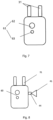
- FIG. 2 to 4 and 7 shows an integrated gripper 10 for use in a robot according to a third embodiment of the present invention.
- the integrated gripper 10 comprises a kernel processor 20, a servo gripper finger member 30, a vision member 60 and an interface member 50.
- the vision member 60 can be a smart camera, which is used for object detection and calculation.
- the kernel processor 20 can also control the vision member 60 as shown in Fig. 2 .
- the advantages of having the vision member 60 comprise providing detecting and view function, and ensuring the control accuracy of the gripper.
- This visual supervision feature makes a gripper more functional and makes the robot system more flexible with compact structure. So the size and weight of the robot are further saved by the third embodiment.
- One way to arrange the vision member 60 is to have a camera 61 and a standalone vision calculation unit 64.
- the camera 61 comprises a camera lighting 62 and a camera lens 63. So integrated lighting is provided for the vision.
- the standalone vision calculation unit 64 is controlled by the kernel processor 20 and capable of outputting results to the kernel processor 2O. With the standalone vision calculation unit 64, the vision member 60 can easily process the imaging information without other module.
- FIG. 2 to 4 and 8 shows an integrated gripper 10 for use in a robot according to a fourth embodiment of the present invention.
- the integrated gripper 10 comprises a kernel processor 20, a servo gripper finger member 30, a pneumatic member 40, a vision member 60 and an interface member 50. It is noted that, the components identical with or similar to those in the above embodiments are given the same reference, and repeated descriptions of some similar elements will be omitted.
- the present embodiment with multi-functional modules has a compact solution with the combination of intelligent grippers, pneumatic function, and view function. Its size and weight are extremely small compared to other products. Therefore, by having several modules, a new gripper can be designed to facilitate its compactness, flexibility and reliability. Furthermore, as each member is formed as a separate module, a user can select among these multi-functions, to save weight and cost.
- the pneumatic member 40 can be not only one, but also more members upon requirement.
Landscapes
- Engineering & Computer Science (AREA)
- Robotics (AREA)
- Mechanical Engineering (AREA)
- Multimedia (AREA)
- Manipulator (AREA)
Description
- Embodiments of the present disclosure generally relate to a gripper, and particularly relate to a gripper in a robot.
- A gripper is usually needed by the robot. Currently, there are lots of grippers in the market, but normally they only have unique function, and a servo driver is further required to work together with the gripper, which generally increase the size, weight and cost of the gripper system.
- Various attempts have been made to make it lighter and smaller, or with more functions. Typical solution is using pneumatic grippers, however, which cannot control the force and position of the grippers. In some cases a pneumatic suction cup is used to pick up objects, but additional valve units are also required.
- Another existing solution is using a servo gripper as shown in
Fig. 1 however, separate drive module should be prepared for the gripper, which increases the complexity a lot. -
US 2007/280812 A1 describes a material handling tool comprising a longitudinal body provided with a proximate end and a distal end is described herein. The handling tool includes a vacuum jaw assembly so mounted to the distal end of the body as to be transversally movable; and a longitudinally movable jaw assembly so mounted to the longitudinal body as to be longitudinally movable between a retracted position where the movable jaw assembly is adjacent to the longitudinal body and an extended position where the movable jaw assembly faces the vacuum jaw assembly. -
US 5237468 A describes a reliable automated storage library by mounting two CCD cameras on a turret plate with two grippers, the CCD cameras providing video support for both grippers. The turret plate is rotatably mounted on the end of an anthropomorphic robot arm so that the cameras and grippers are rotated and angled into position as needed for viewing or gripping. A CCD camera is positioned to view a tape cartridge for capturing an image of the label attached thereto. While the captured image is being processed to verify its identity, the first gripper is rotated into position and moved forward to grip the desired tape cartridge. The robot arm then moves the camera and gripper assembly to a tape drive and rotates the second gripper into position to remove another tape cartridge from the tape drive. The turret plate is again rotated to position the first gripper to insert the verified tape cartridge into the tape drive. Thus pick-before-place operations may be performed by a single camera and two grippers. The second camera is added to increase reliability for pick-before-place. If either gripper fails, a single camera and a single gripper in any combination will allow the automated storage library to continue to provide storage and retrieval functions. -
US 2009/320417 A1 describes an end of arm tool that is capable of handling fragile items such as eggs that are packaged in containers (e.g., egg cartons) that require special handling is provided. The end of arm tool comprises pivotal clamps operated by slidingcontact linear actuators and return springs. A retractable gripper for placing divider sheets between packages in the cases may be disposed above the clamps and oriented 90 degrees from the clamps, so that the clamps and gripper may be attached to the same tool without either obstructing the operation of the other. In addition, a method of loading packages, and optionally divider sheets, into cases using the end of arm tool apparatus of the present invention is provided. -
KR 20140025073 A -
EP 0841297 A1 describes a baggage handling device comprising, in combination, a vacuum gripping foot and a non-vacuum, mechanical engagement device such as a simple hook or a power operated claw, with means to select either the vacuum gripping foot, or the mechanical device as appropriate, for any particular item of baggage; with a powered hoisting means to raise and lower the duplex unit, as necessary in a baggage handling sequence. - In view of the foregoing, there is a need in the art to develop an improved gripper with the combination of servo gripping, pneumatic suction and vision functions with compact solution.
- The object of the present invention is to provide an integrated gripper, makes the gripper more functional with compact solution and makes the robot system more flexible.
- According to one aspect of the invention, there is provided an integrated gripper. Said integrated gripper comprises a kernel processor, a servo gripper finger member, a pneumatic member and an interface member; said servo gripper finger member comprises at least two fingers, a servo actuator and a motor, said fingers being driven by said motor to grip and/or move an object; said pneumatic member, comprising a cup, a vacuum generator and a pneumatic actuator, is configured to suck and/or blow off an object; said kernel processor is configured to control said servo actuator of said servo gripper finger member and said pneumatic actuator of said pneumatic member; and said interface member comprises a power supply interface, a bus interface and an air input interface, said power supply interface, said bus interface and said air input interface being connectable to a power supply, a bus and an air input respectively.
- According to a preferred embodiment of the present invention,said gripper further comprises a vision member, for object detection and calculation, and said kernel processor is configured to control said vision member.
- According to a preferred embodiment of the present invention, said vision member comprises a camera and a standalone calculation unit, said camera comprising a camera lighting and a camera lens, said standalone calculation unit being controlled by said kernel processor and capable of outputting results to said kernel processor.
- According to a preferred embodiment of the present invention, said pneumatic member further comprises a filter and a pressure sensor, said pressure sensor being configured to detect the air pressure of said cup.
- According to a preferred embodiment of the present invention, said pneumatic member further comprises a vacuum generator, a first valve and a second valve, said first valve and said second valve being configured to open and close alternatively, to make said cup suck or blow off an object.
- According to a preferred embodiment of the present invention, said integrated gripper comprises one, two or more than two said pneumatic members.
- According to an optional exemplary embodiment, there is provided an integrated gripper. Said integrated gripper comprises a kernel processor, a servo gripper finger member, a vision member and an interface member; said servo gripper finger member comprises at least two fingers, a servo actuator and a motor, said fingers being driven by said motor to grip and/or move an object; said vision member is used for object detection and calculation; said kernel processor is configured to control said servo actuator of said servo gripper finger member and said vision member; and said interface member comprises a power supply interface and a bus interface, said power supply interface and said bus interface being connected to a power supply and a bus respectively.
- According to a preferred embodiment of the present invention, said vision member comprises a camera and a standalone vision calculation unit, said camera comprising a camera lighting and a camera lens, said standalone vision calculation unit being controlled by said kernel processor and capable of outputting results to said kernel processor.
- According to a preferred embodiment of the present invention, said servo gripper finger member further comprises a gear box and a pinion-rack mechanism, said gear box and said pinion-rack mechanism being configured to drive said fingers to move in parallel, for gripping and/or moving an object.
- According to a preferred embodiment of the present invention, said kernel processor controls the current, speed and position of said servo gripper finger member through said servo actuator.
- According to a preferred embodiment of the present invention, said servo gripper finger member further comprises a position feedback unit to form a closed-loop control.
- According to a preferred embodiment of the present invention, said integrated gripper is controlled by a user through said bus.
- According to a preferred embodiment of the present invention, said bus interface is configured to accept the control signal from the user, and keep the user monitor the status of said integrated gripper.
- According to a preferred embodiment of the present invention, said power supply is a direct-current (DC) power supply, and said motor is a DC motor.
- According to another aspect of the invention, there is provided a robot comprising the integrated gripper as described above.
- Compared with the existing prior arts, the solution for gripper can achieve several advantages as below.
- Multi-functions: the present invention integrates multi-functional modules, to conduct motion control, valve control and visual supervision.
- Intelligent automatic control: the present invention can improve control speed of the whole robot, while ensure the control accuracy of the gripper.
- Compact: the present invention has a compact solution with the combination of intelligent grippers, pneumatic function, and view-function. Furthermore, the control unit is also inside the gripper. Its size and weight are extremely small compared to other products.
- Other features and advantages of embodiments of the present application will also be understood from the following description of specific exemplary embodiments when read in conjunction with the accompanying drawings, which illustrate, byway of example, the principles of the invention.
- The above and other features of the present disclosure will become more apparent through detailed explanation on the embodiments as illustrated in the description with reference to the accompanying drawings, throughout which like reference numbers represent same or similar components and wherein:
-
Fig. 1 shows the structure of a conventional gripper; -
Fig. 2 shows a scheme of the kernel processor of the integrated gripper according to an embodiment of the present invention; -
Fig. 3 shows a scheme of the servo gripper finger member of the integrated gripper according to an embodiment of the present invention; -
Fig. 4 shows a scheme of the pneumatic member of the integrated gripper according to an embodiment of the present invention; -
Fig. 5 shows an integrated gripper according to a first embodiment of the present invention; -
Fig. 6 shows an integrated gripper according to a second embodiment of the present invention; -
Fig. 7 shows an integrated gripper according to a third embodiment of the present invention; -
Fig. 8 shows an integrated gripper according to a fourth embodiment of the present invention; - Throughout the figures, same or similar reference numbers indicate same or similar elements.
- Hereinafter, solutions as provided the present disclosure will be described in details through embodiments with reference to the accompanying drawings. It should be appreciated that these embodiments are presented only to enable those skilled in the art to better understand and implement the present disclosure, not intended to limit the scope of the present disclosure in any manner.
- Generally, all terms used in the claims are to be interpreted according to their ordinary meaning in the technical field, unless explicitly defined otherwise herein. All references to "a/an/the/said [element, device, component, means, step, etc.]" are to be interpreted openly as referring to at least one instance of said element, device, component, means, unit, step, etc., without excluding a plurality of such devices, components, means, units, steps, etc., unless explicitly stated otherwise. Besides, the indefinite article "a/an" as used herein does not exclude a plurality of such steps, units, modules, devices, and objects, and etc.
- In general, embodiments of the present application provide a new gripper of a robot. As will be apparent from the further discussions below, several options modules, including a servo gripper finger member, at least one pneumatic member and a vision member, are employed to provide an integrated gripper.
- Reference is first made to
Figs. 2 to 5 , which shows anintegrated gripper 10 for use in a robot according to a first embodiment of the present invention. Theintegrated gripper 10 comprises akernel processor 20, a servogripper finger member 30, apneumatic member 40 and aninterface member 50. The servogripper finger member 30 comprises two ormore fingers 31 as shown inFig. 5 , and aservo actuator 32, amotor 33 as shown inFig. 3 . Thefingers 32 are driven by themotor 33 to grip or move an object. Thepneumatic member 40 is used for sucking or blowing off an object As shown inFig. 4 and5 , it comprises acup 41, avacuum generator 42 and a pneumatic actuator 43. - As shown in
Fig. 2 , thekernel processor 20 is configured to control theservo actuator 32 of the servogripper finger member 30 and the pneumatic actuator 43 of thepneumatic member 40. - As also shown in
Fig. 2 , theinterface member 50 comprises apower supply interface 51, abus interface 52 and anair input interface 53. Thepower supply interface 51, thebus interface 52 and theair input interface 53 are connected to a power supply, a bus and an air input respectively. - Therefore, by having the servo
gripper finger member 30 and thepneumatic member 40, a new gripper can be designed to achieve multi-functions with compact solution. This new gripper with control system has bus communication function, servo gripping function, pneumatic suction and blow off functions, etc. All functions are combined in one gripper and each function can also be modularized. For example, a user can just select servo gripping function, which includes the servo gripper module only, to save weight and cost. - The above describes one kind of
integrated gripper 10, but the structures of thegripper 10 are not limited to the above, and it can also adopt, but not limited to, other structures as described below. - As shown in
Fig. 3 , one way to arrange theservo finger member 30 is to have agear box 34 and a pinion-rack mechanism 35. Thegear box 34 and the pinion-rack mechanism drive thefingers 31 to move in parallel. So thefingers 31 can grip or move an object. - As shown in
Fig. 4 , one way to arrange the pneumatic member is to have afilter 44 and apressure sensor 45. So the air pressure of thecup 41 can be detected by thepressure sensor 45. - As shown in
Fig. 4 , another way to arrange the pneumatic member is to have avacuum generator 42, afirst valve 46 and asecond valve 47. When thefirst valve 46 open and thesecond valve 47 close, it will form a vacuum by thevacuum generator 42 around thecup 41, so thecup 41 can suck an object. When thefirst valve 46 close and thesecond valve 47 open, it will form a positive pressure around thecup 41, so thecup 41 can blow off an object. - According to another embodiment of the present invention, the
kernel processor 20 controls the current, speed and position of the servogripper finger member 30 through theservo actuator 32. Furthermore, the servo gripper finger member can also have a position feedback unit to form a closed-loop control. So it can improve control speed of the gripper, while ensure the control accuracy of the gripper. - According to another embodiment of the present invention, the
kernel processor 20 of theintegrated gripper 10 is controlled by a user through the bus. Furthermore, thebus interface 52 can also accept the control signal from the user, and keep the user monitor the status of theintegrated gripper 10. As the control unit is inside the gripper. Its size and weight are extremely small compared to other products. - According to another embodiment of the present invention, the power supply is a DC power supply, so the motor is a DC motor. However, the power supply can also be a AC power supply upon requirements.
- Reference is next made to
Figs. 2 to 4 and6 , which shows anintegrated gripper 10 for use in a robot according to a second embodiment of the present invention. - The
integrated gripper 10 comprises akernel processor 20, a servogripper finger member 30, two or morepneumatic members 40 and aninterface member 50. It is noted that, in the second and subsequent embodiments, the components identical with or similar to those in the first embodiment are given the same reference numerals, and repeated descriptions of some similar elements will be omitted. - As shown in
Fig. 6 , thegripper 10 according to the second embodiment can have two or more channels of pneumatic functions. By having severalpneumatic members 40, a new gripper can be designed to increase the working area and facilitate the flexibility of suction and blowing off functions in object picking. - Reference is next made to
Figs. 2 to 4 and7 , which shows anintegrated gripper 10 for use in a robot according to a third embodiment of the present invention. - The
integrated gripper 10 comprises akernel processor 20, a servogripper finger member 30, avision member 60 and aninterface member 50. - The
vision member 60 can be a smart camera, which is used for object detection and calculation. Thekernel processor 20 can also control thevision member 60 as shown inFig. 2 . - The advantages of having the
vision member 60 comprise providing detecting and view function, and ensuring the control accuracy of the gripper. This visual supervision feature makes a gripper more functional and makes the robot system more flexible with compact structure. So the size and weight of the robot are further saved by the third embodiment. - One way to arrange the
vision member 60 is to have acamera 61 and a standalonevision calculation unit 64. Thecamera 61 comprises acamera lighting 62 and acamera lens 63. So integrated lighting is provided for the vision. And the standalonevision calculation unit 64 is controlled by thekernel processor 20 and capable of outputting results to the kernel processor 2O. With the standalonevision calculation unit 64, thevision member 60 can easily process the imaging information without other module. - Reference is next made to
Figs. 2 to 4 and8 , which shows anintegrated gripper 10 for use in a robot according to a fourth embodiment of the present invention. - As shown in
Fig. 8 , theintegrated gripper 10 comprises akernel processor 20, a servogripper finger member 30, apneumatic member 40, avision member 60 and aninterface member 50. It is noted that, the components identical with or similar to those in the above embodiments are given the same reference, and repeated descriptions of some similar elements will be omitted. - The present embodiment with multi-functional modules has a compact solution with the combination of intelligent grippers, pneumatic function, and view function. Its size and weight are extremely small compared to other products. Therefore, by having several modules, a new gripper can be designed to facilitate its compactness, flexibility and reliability. Furthermore, as each member is formed as a separate module, a user can select among these multi-functions, to save weight and cost.
- Another embodiment of the present application, the
pneumatic member 40 can be not only one, but also more members upon requirement.
Claims (13)
- An integrated gripper (10), whereinsaid integrated gripper (10) comprises a kernel processor (20), a servo gripper finger member (30), a pneumatic member (40) and an interface member (50);said servo gripper finger member (30) comprises at least two fingers (31 ), a servo actuator (32) and a motor (33), said fingers (32) being driven by said motor (33) to grip and/or move an object;said pneumatic member (40), comprising a cup (41), a vacuum generator (42) and a pneumatic actuator (43), is configured to suck and/or blow off an object;said kernel processor (20) is configured to control said servo actuator (32) of said servo gripper finger member (30) and said pneumatic actuator (43) of said pneumatic member (40); andsaid interface member (50) comprises a power supply interface (51), a bus interface (52) and an air input interface (53), said power supply interface (51), said bus interface (52) and said air input interface (53) being connectable to a power supply, a bus and an air input respectively.
- The integrated gripper (10) according to claim 1, characterized in that,
said gripper (10) further comprises a vision member (60), for object detection and calculation, and said kernel processor (20) is configured to control said vision member (60). - The integrated gripper (10) according to claim 2, characterized in that,said vision member (60) comprises a camera (61) and a standalone vision calculation unit (64),said camera (61) comprising a camera lighting (62) and a camera lens (63),said standalone vision calculation unit (64) being controlled by said kernel processor (20) and capable of outputting results to said kernel processor (20).
- The integrated gripper (10) according to claim 1, characterized in that,said pneumatic member (40) further comprises a filter (44) and a pressure sensor (45),said pressure sensor (45) being configured to detect the air pressure of said cup (41),
- The integrated gripper (10) according to claim 1, characterized in that,said pneumatic member (40) further comprises a vacuum generator (42), a first valve (46) and a second valve (47),said first valve (46) and said second valve (47) being configured to open and close alternatively, to make said cup (41) suck or blow off an object.
- The integrated gripper (10) according to claim 1, characterized in that,
said integrated gripper (10) comprises one, two or more than two said pneumatic members (40). - The integrated gripper (10) according to any one of claims 1 to 6, characterized in that,said servo gripper finger member (30) further comprises a gear box (34) and a pinion-rack mechanism (35),said gear box (34) and said pinion-rack mechanism (35) being configured to drive said fingers (31) to move in parallel, for gripping and/or moving an object.
- The integrated gripper (10) according to claim 7, characterized in that,
said kernel processor (20) controls the current, speed and position of said servo gripper finger member (30) through said servo actuator (32). - The integrated gripper (10) according to claim 8, characterized in that,
said servo gripper finger member (30) further comprises a position feedback unit to form a closed-loop control. - The integrated gripper (10) according to any one of claims 1 to 6, characterized in that, said integrated gripper (10) is controlled by a user through said bus.
- The integrated gripper (10) according to claim 10, characterized in that,
said bus interface (52) is configured to accept the control signal from the user, and keep the user monitor the status of said integrated gripper (10). - The integrated gripper (10) according to any one of claims 1 to 6, characterized in that, said power supply is a direct-current (DC) power supply, and said motor is a DC motor.
- A robot comprising the integrated gripper (10) according any one of claims 1 to 12.
Applications Claiming Priority (1)
| Application Number | Priority Date | Filing Date | Title |
|---|---|---|---|
| PCT/CN2014/090587 WO2016070412A1 (en) | 2014-11-07 | 2014-11-07 | An integrated gripper and a robot |
Publications (3)
| Publication Number | Publication Date |
|---|---|
| EP3215319A1 EP3215319A1 (en) | 2017-09-13 |
| EP3215319A4 EP3215319A4 (en) | 2018-07-11 |
| EP3215319B1 true EP3215319B1 (en) | 2025-01-01 |
Family
ID=55908427
Family Applications (1)
| Application Number | Title | Priority Date | Filing Date |
|---|---|---|---|
| EP14905627.7A Active EP3215319B1 (en) | 2014-11-07 | 2014-11-07 | An integrated gripper and a robot |
Country Status (3)
| Country | Link |
|---|---|
| EP (1) | EP3215319B1 (en) |
| ES (1) | ES3014716T3 (en) |
| WO (1) | WO2016070412A1 (en) |
Families Citing this family (14)
| Publication number | Priority date | Publication date | Assignee | Title |
|---|---|---|---|---|
| US10343284B2 (en) | 2015-08-26 | 2019-07-09 | Berkshire Grey, Inc. | Systems and methods for providing contact detection in an articulated arm |
| US11370128B2 (en) | 2015-09-01 | 2022-06-28 | Berkshire Grey Operating Company, Inc. | Systems and methods for providing dynamic robotic control systems |
| EP3344422B1 (en) | 2015-09-01 | 2020-11-04 | Berkshire Grey, Inc. | Systems and methods for providing dynamic robotic control systems |
| EP4046761B1 (en) | 2016-01-08 | 2025-03-26 | Berkshire Grey Operating Company, Inc. | Systems and methods for acquiring and moving objects |
| EP3263292B1 (en) * | 2016-06-28 | 2025-07-16 | Tata Consultancy Services Limited | Adaptive gripper device |
| SE543130C2 (en) | 2018-04-22 | 2020-10-13 | Zenrobotics Oy | A waste sorting robot gripper |
| SE544090C2 (en) | 2018-04-22 | 2021-12-21 | Zenrobotics Oy | Waste Sorting Gantry Robot |
| SE544741C2 (en) * | 2018-05-11 | 2022-11-01 | Genie Ind Bv | Waste Sorting Gantry Robot and associated method |
| GB2592410B (en) * | 2020-02-27 | 2022-09-07 | Dyson Technology Ltd | Robot hand |
| SE544165C2 (en) | 2020-06-24 | 2022-02-15 | Zenrobotics Oy | Waste Sorting Robot |
| US11938618B2 (en) | 2020-07-22 | 2024-03-26 | Berkshire Grey Operating Company, Inc. | Systems and methods for object processing using a passively folding vacuum gripper |
| US11964386B2 (en) | 2020-07-22 | 2024-04-23 | Berkshire Grey Operating Company, Inc. | Systems and methods for object processing using a vacuum gripper that provides object retention by shroud inversion |
| EP4217156A1 (en) * | 2020-09-28 | 2023-08-02 | Icol Group Ltd | A gripping device of a manipulator |
| SE544103C2 (en) | 2020-10-28 | 2021-12-21 | Zenrobotics Oy | Waste Sorting Robot with gripper that releases waste object at a throw position |
Family Cites Families (11)
| Publication number | Priority date | Publication date | Assignee | Title |
|---|---|---|---|---|
| US4909376A (en) * | 1987-10-06 | 1990-03-20 | Western Technologies Automation, Inc. | Robotically controlled component feed mechanism visually monitoring part orientation |
| JPH0329117Y2 (en) * | 1987-11-06 | 1991-06-21 | ||
| US5237468A (en) | 1991-10-15 | 1993-08-17 | International Business Machines Corporation | Camera and gripper assembly for an automated storage library |
| GB9623306D0 (en) | 1996-11-08 | 1997-01-08 | Palamatic Handling Syst | Baggage handling device |
| JP5013270B2 (en) * | 2006-02-02 | 2012-08-29 | 株式会社安川電機 | Robot system |
| US20070280812A1 (en) * | 2006-05-17 | 2007-12-06 | Axium Inc. | Tool and method for mixed palletizing/depalletizing |
| US20090320417A1 (en) * | 2006-06-29 | 2009-12-31 | Smart Motion Robotics, Inc. | Linear actuated robotic packaging device and method |
| CN100512621C (en) * | 2007-03-06 | 2009-07-15 | 江苏大学 | Terminal executor of fruit and vegetable picking robot |
| CN100591202C (en) * | 2008-05-05 | 2010-02-24 | 江苏大学 | Flexible picking device and method for citrus picking robot |
| FR2960173B1 (en) * | 2010-05-21 | 2013-12-20 | Rise Ba | SYSTEM FOR PREHENDING FIXED OBJECTS ON A ROBOTIC ASSEMBLY, COMPRISING TWO MEANS OF GRIPPING |
| KR101382641B1 (en) | 2012-08-21 | 2014-04-07 | 재단법인대구경북과학기술원 | Gripping device having gripping function and suction function of object |
-
2014
- 2014-11-07 ES ES14905627T patent/ES3014716T3/en active Active
- 2014-11-07 EP EP14905627.7A patent/EP3215319B1/en active Active
- 2014-11-07 WO PCT/CN2014/090587 patent/WO2016070412A1/en not_active Ceased
Also Published As
| Publication number | Publication date |
|---|---|
| EP3215319A1 (en) | 2017-09-13 |
| WO2016070412A1 (en) | 2016-05-12 |
| EP3215319A4 (en) | 2018-07-11 |
| ES3014716T3 (en) | 2025-04-24 |
Similar Documents
| Publication | Publication Date | Title |
|---|---|---|
| EP3215319B1 (en) | An integrated gripper and a robot | |
| JP7727046B2 (en) | Robot hand, robot and robot system | |
| JP5480340B2 (en) | Take-out robot system using roller device | |
| US10858188B2 (en) | Gripping device and conveying apparatus | |
| US10226865B2 (en) | Gripper and robot system | |
| US20220297312A1 (en) | Multi-mode robotic end effector | |
| CN110340863B (en) | Autonomous mobile transfer robot | |
| JP6741329B1 (en) | System to change the tool of gripper device | |
| TWI794989B (en) | Velocity control-based robotic system, method to control a robotic system and computer program product embodied in a non-transitory computer readable medium | |
| JP6997137B2 (en) | Grippers and robot systems | |
| JP2022531575A (en) | Logistic device | |
| CN104203504B (en) | Robot system | |
| US12466063B2 (en) | Robotic system with gripping mechanisms, and related systems and methods | |
| CN115703244A (en) | Robotic system with gripping mechanism and related systems and methods | |
| KR102050875B1 (en) | Apparatus for transporting a charge | |
| US20240157565A1 (en) | Robotic system transfer unit cell and method of operation thereof | |
| JP2020163483A (en) | robot | |
| CN115592691A (en) | Robotic system with gripping mechanism and related systems and methods | |
| KR20240175941A (en) | Hybrid gripper capable of bin picking and shelf picking | |
| WO2017212896A1 (en) | Component feeding device | |
| JP2024171607A (en) | Picking System | |
| CN119968249A (en) | Robotic transportation system and method thereof | |
| WO2019009287A1 (en) | Conveying device and conveying method |
Legal Events
| Date | Code | Title | Description |
|---|---|---|---|
| STAA | Information on the status of an ep patent application or granted ep patent |
Free format text: STATUS: THE INTERNATIONAL PUBLICATION HAS BEEN MADE |
|
| PUAI | Public reference made under article 153(3) epc to a published international application that has entered the european phase |
Free format text: ORIGINAL CODE: 0009012 |
|
| STAA | Information on the status of an ep patent application or granted ep patent |
Free format text: STATUS: REQUEST FOR EXAMINATION WAS MADE |
|
| 17P | Request for examination filed |
Effective date: 20170420 |
|
| AK | Designated contracting states |
Kind code of ref document: A1 Designated state(s): AL AT BE BG CH CY CZ DE DK EE ES FI FR GB GR HR HU IE IS IT LI LT LU LV MC MK MT NL NO PL PT RO RS SE SI SK SM TR |
|
| AX | Request for extension of the european patent |
Extension state: BA ME |
|
| DAX | Request for extension of the european patent (deleted) | ||
| A4 | Supplementary search report drawn up and despatched |
Effective date: 20180613 |
|
| RIC1 | Information provided on ipc code assigned before grant |
Ipc: B25J 15/06 20060101ALI20180607BHEP Ipc: B25J 19/02 20060101ALI20180607BHEP Ipc: B25J 15/00 20060101ALI20180607BHEP Ipc: B25J 9/00 20060101AFI20180607BHEP Ipc: B25J 15/02 20060101ALI20180607BHEP |
|
| STAA | Information on the status of an ep patent application or granted ep patent |
Free format text: STATUS: EXAMINATION IS IN PROGRESS |
|
| 17Q | First examination report despatched |
Effective date: 20210628 |
|
| GRAP | Despatch of communication of intention to grant a patent |
Free format text: ORIGINAL CODE: EPIDOSNIGR1 |
|
| STAA | Information on the status of an ep patent application or granted ep patent |
Free format text: STATUS: GRANT OF PATENT IS INTENDED |
|
| INTG | Intention to grant announced |
Effective date: 20240927 |
|
| GRAS | Grant fee paid |
Free format text: ORIGINAL CODE: EPIDOSNIGR3 |
|
| GRAA | (expected) grant |
Free format text: ORIGINAL CODE: 0009210 |
|
| STAA | Information on the status of an ep patent application or granted ep patent |
Free format text: STATUS: THE PATENT HAS BEEN GRANTED |
|
| RAP3 | Party data changed (applicant data changed or rights of an application transferred) |
Owner name: ABB SCHWEIZ AG |
|
| AK | Designated contracting states |
Kind code of ref document: B1 Designated state(s): AL AT BE BG CH CY CZ DE DK EE ES FI FR GB GR HR HU IE IS IT LI LT LU LV MC MK MT NL NO PL PT RO RS SE SI SK SM TR |
|
| REG | Reference to a national code |
Ref country code: GB Ref legal event code: FG4D |
|
| REG | Reference to a national code |
Ref country code: CH Ref legal event code: EP |
|
| REG | Reference to a national code |
Ref country code: DE Ref legal event code: R096 Ref document number: 602014091415 Country of ref document: DE |
|
| REG | Reference to a national code |
Ref country code: IE Ref legal event code: FG4D |
|
| REG | Reference to a national code |
Ref country code: ES Ref legal event code: FG2A Ref document number: 3014716 Country of ref document: ES Kind code of ref document: T3 Effective date: 20250424 |
|
| REG | Reference to a national code |
Ref country code: LT Ref legal event code: MG9D |
|
| REG | Reference to a national code |
Ref country code: NL Ref legal event code: MP Effective date: 20250101 |
|
| REG | Reference to a national code |
Ref country code: AT Ref legal event code: MK05 Ref document number: 1755757 Country of ref document: AT Kind code of ref document: T Effective date: 20250101 |
|
| PG25 | Lapsed in a contracting state [announced via postgrant information from national office to epo] |
Ref country code: NL Free format text: LAPSE BECAUSE OF FAILURE TO SUBMIT A TRANSLATION OF THE DESCRIPTION OR TO PAY THE FEE WITHIN THE PRESCRIBED TIME-LIMIT Effective date: 20250101 |
|
| PG25 | Lapsed in a contracting state [announced via postgrant information from national office to epo] |
Ref country code: FI Free format text: LAPSE BECAUSE OF FAILURE TO SUBMIT A TRANSLATION OF THE DESCRIPTION OR TO PAY THE FEE WITHIN THE PRESCRIBED TIME-LIMIT Effective date: 20250101 |
|
| PG25 | Lapsed in a contracting state [announced via postgrant information from national office to epo] |
Ref country code: PL Free format text: LAPSE BECAUSE OF FAILURE TO SUBMIT A TRANSLATION OF THE DESCRIPTION OR TO PAY THE FEE WITHIN THE PRESCRIBED TIME-LIMIT Effective date: 20250101 |
|
| PG25 | Lapsed in a contracting state [announced via postgrant information from national office to epo] |
Ref country code: IS Free format text: LAPSE BECAUSE OF FAILURE TO SUBMIT A TRANSLATION OF THE DESCRIPTION OR TO PAY THE FEE WITHIN THE PRESCRIBED TIME-LIMIT Effective date: 20250501 Ref country code: NO Free format text: LAPSE BECAUSE OF FAILURE TO SUBMIT A TRANSLATION OF THE DESCRIPTION OR TO PAY THE FEE WITHIN THE PRESCRIBED TIME-LIMIT Effective date: 20250401 |
|
| PG25 | Lapsed in a contracting state [announced via postgrant information from national office to epo] |
Ref country code: HR Free format text: LAPSE BECAUSE OF FAILURE TO SUBMIT A TRANSLATION OF THE DESCRIPTION OR TO PAY THE FEE WITHIN THE PRESCRIBED TIME-LIMIT Effective date: 20250101 |
|
| PG25 | Lapsed in a contracting state [announced via postgrant information from national office to epo] |
Ref country code: LV Free format text: LAPSE BECAUSE OF FAILURE TO SUBMIT A TRANSLATION OF THE DESCRIPTION OR TO PAY THE FEE WITHIN THE PRESCRIBED TIME-LIMIT Effective date: 20250101 Ref country code: PT Free format text: LAPSE BECAUSE OF FAILURE TO SUBMIT A TRANSLATION OF THE DESCRIPTION OR TO PAY THE FEE WITHIN THE PRESCRIBED TIME-LIMIT Effective date: 20250502 |
|
| PG25 | Lapsed in a contracting state [announced via postgrant information from national office to epo] |
Ref country code: GR Free format text: LAPSE BECAUSE OF FAILURE TO SUBMIT A TRANSLATION OF THE DESCRIPTION OR TO PAY THE FEE WITHIN THE PRESCRIBED TIME-LIMIT Effective date: 20250402 Ref country code: BG Free format text: LAPSE BECAUSE OF FAILURE TO SUBMIT A TRANSLATION OF THE DESCRIPTION OR TO PAY THE FEE WITHIN THE PRESCRIBED TIME-LIMIT Effective date: 20250101 |
|
| PG25 | Lapsed in a contracting state [announced via postgrant information from national office to epo] |
Ref country code: AT Free format text: LAPSE BECAUSE OF FAILURE TO SUBMIT A TRANSLATION OF THE DESCRIPTION OR TO PAY THE FEE WITHIN THE PRESCRIBED TIME-LIMIT Effective date: 20250101 |
|
| PG25 | Lapsed in a contracting state [announced via postgrant information from national office to epo] |
Ref country code: CZ Free format text: LAPSE BECAUSE OF FAILURE TO SUBMIT A TRANSLATION OF THE DESCRIPTION OR TO PAY THE FEE WITHIN THE PRESCRIBED TIME-LIMIT Effective date: 20250101 |
|
| PG25 | Lapsed in a contracting state [announced via postgrant information from national office to epo] |
Ref country code: SE Free format text: LAPSE BECAUSE OF FAILURE TO SUBMIT A TRANSLATION OF THE DESCRIPTION OR TO PAY THE FEE WITHIN THE PRESCRIBED TIME-LIMIT Effective date: 20250101 |
|
| REG | Reference to a national code |
Ref country code: DE Ref legal event code: R097 Ref document number: 602014091415 Country of ref document: DE |
|
| PG25 | Lapsed in a contracting state [announced via postgrant information from national office to epo] |
Ref country code: SM Free format text: LAPSE BECAUSE OF FAILURE TO SUBMIT A TRANSLATION OF THE DESCRIPTION OR TO PAY THE FEE WITHIN THE PRESCRIBED TIME-LIMIT Effective date: 20250101 |
|
| PG25 | Lapsed in a contracting state [announced via postgrant information from national office to epo] |
Ref country code: DK Free format text: LAPSE BECAUSE OF FAILURE TO SUBMIT A TRANSLATION OF THE DESCRIPTION OR TO PAY THE FEE WITHIN THE PRESCRIBED TIME-LIMIT Effective date: 20250101 |
|
| PG25 | Lapsed in a contracting state [announced via postgrant information from national office to epo] |
Ref country code: EE Free format text: LAPSE BECAUSE OF FAILURE TO SUBMIT A TRANSLATION OF THE DESCRIPTION OR TO PAY THE FEE WITHIN THE PRESCRIBED TIME-LIMIT Effective date: 20250101 |
|
| PG25 | Lapsed in a contracting state [announced via postgrant information from national office to epo] |
Ref country code: RO Free format text: LAPSE BECAUSE OF FAILURE TO SUBMIT A TRANSLATION OF THE DESCRIPTION OR TO PAY THE FEE WITHIN THE PRESCRIBED TIME-LIMIT Effective date: 20250101 |
|
| PG25 | Lapsed in a contracting state [announced via postgrant information from national office to epo] |
Ref country code: SK Free format text: LAPSE BECAUSE OF FAILURE TO SUBMIT A TRANSLATION OF THE DESCRIPTION OR TO PAY THE FEE WITHIN THE PRESCRIBED TIME-LIMIT Effective date: 20250101 |
|
| PLBE | No opposition filed within time limit |
Free format text: ORIGINAL CODE: 0009261 |
|
| STAA | Information on the status of an ep patent application or granted ep patent |
Free format text: STATUS: NO OPPOSITION FILED WITHIN TIME LIMIT |
|
| 26N | No opposition filed |
Effective date: 20251002 |
|
| PGFP | Annual fee paid to national office [announced via postgrant information from national office to epo] |
Ref country code: DE Payment date: 20251119 Year of fee payment: 12 |
|
| PGFP | Annual fee paid to national office [announced via postgrant information from national office to epo] |
Ref country code: IT Payment date: 20251125 Year of fee payment: 12 |
|
| PGFP | Annual fee paid to national office [announced via postgrant information from national office to epo] |
Ref country code: FR Payment date: 20251126 Year of fee payment: 12 |
|
| PGFP | Annual fee paid to national office [announced via postgrant information from national office to epo] |
Ref country code: ES Payment date: 20251229 Year of fee payment: 12 |