EP3214775A1 - Receiving device and method - Google Patents
Receiving device and method Download PDFInfo
- Publication number
- EP3214775A1 EP3214775A1 EP15856089.6A EP15856089A EP3214775A1 EP 3214775 A1 EP3214775 A1 EP 3214775A1 EP 15856089 A EP15856089 A EP 15856089A EP 3214775 A1 EP3214775 A1 EP 3214775A1
- Authority
- EP
- European Patent Office
- Prior art keywords
- reception device
- frame part
- action block
- circuit
- frame
- Prior art date
- Legal status (The legal status is an assumption and is not a legal conclusion. Google has not performed a legal analysis and makes no representation as to the accuracy of the status listed.)
- Granted
Links
Images








Classifications
-
- H—ELECTRICITY
- H04—ELECTRIC COMMUNICATION TECHNIQUE
- H04W—WIRELESS COMMUNICATION NETWORKS
- H04W52/00—Power management, e.g. Transmission Power Control [TPC] or power classes
- H04W52/02—Power saving arrangements
- H04W52/0209—Power saving arrangements in terminal devices
- H04W52/0261—Power saving arrangements in terminal devices managing power supply demand, e.g. depending on battery level
- H04W52/0274—Power saving arrangements in terminal devices managing power supply demand, e.g. depending on battery level by switching on or off the equipment or parts thereof
- H04W52/028—Power saving arrangements in terminal devices managing power supply demand, e.g. depending on battery level by switching on or off the equipment or parts thereof switching on or off only a part of the equipment circuit blocks
-
- H—ELECTRICITY
- H04—ELECTRIC COMMUNICATION TECHNIQUE
- H04B—TRANSMISSION
- H04B1/00—Details of transmission systems, not covered by a single one of groups H04B3/00 - H04B13/00; Details of transmission systems not characterised by the medium used for transmission
- H04B1/06—Receivers
- H04B1/16—Circuits
-
- H—ELECTRICITY
- H04—ELECTRIC COMMUNICATION TECHNIQUE
- H04L—TRANSMISSION OF DIGITAL INFORMATION, e.g. TELEGRAPHIC COMMUNICATION
- H04L27/00—Modulated-carrier systems
- H04L27/0014—Carrier regulation
-
- H—ELECTRICITY
- H04—ELECTRIC COMMUNICATION TECHNIQUE
- H04L—TRANSMISSION OF DIGITAL INFORMATION, e.g. TELEGRAPHIC COMMUNICATION
- H04L27/00—Modulated-carrier systems
- H04L27/26—Systems using multi-frequency codes
- H04L27/2601—Multicarrier modulation systems
- H04L27/2647—Arrangements specific to the receiver only
- H04L27/2655—Synchronisation arrangements
- H04L27/2657—Carrier synchronisation
Definitions
- the present disclosure relates to a reception device and a reception method.
- the disclosure relates to a reception device and a reception method that achieve reduction in electric power consumption while data separated in a time direction is partially received.
- T2 frames serving as desired signals
- FEF future extension frame
- reception devices of the respective techniques independently detect respective signals to receive.
- a reception device configured to receive the T2 frame and a reception device configured to receive the FEF independently detect the respective signals to receive.
- P1 and P2 symbols in the T2 frame include transmission information about a signal, including an FFTSIZE, a data length, a guard interval ratio, the number of times of repetitions of the T2 frame, whether the FEF is present, an FEF part length, and so on with respect to the desired signal. Accordingly, a receiving side can recognize the presence of the FEF part and duration thereof by acquiring these items of the information.
- Non-patent Document 1 ETSI EN 302 755 V1.3.1, Frame structure channel coding and modulation for a second generation digital terrestrial television broadcasting system (DVB-T2) 2012, 04, the home page of the DVB, [searched on October 9, 2014], the Internet ⁇ URL: http://www.dvb.org/technology/standards/dvb-t2>
- the segment in the ISDB-T is separated in a frequency direction and thus needs to be received continuously in the time direction. For this reason, this technology has not contributed to reduction in electric power consumption when the FEF in the DVB-T2 is present.
- the present disclosure has been made by taking such a situation into account and an object thereof is to achieve lower electric power necessary while data separated in a time direction is partially received.
- a reception device includes an intermittent action block that works solely during a first frame part when receiving data obtained by time-division multiplexing of the first frame part and a second frame part, which second frame has a structure different from a structure of the first frame, and a constant action block that constantly monitors the first frame part and the second frame part and controls an action of the intermittent action block.
- the intermittent action block includes an information acquisition unit configured to acquire transmission information regarding the first frame part and the second frame part and is able to work solely during the first frame part after the information acquisition unit acquires the transmission information regarding the first frame part and the second frame part.
- the first frame part is a T2 frame part and the second frame part is an FEF part.
- the constant action block is able to carry out control of stopping and restarting the action of the intermittent action block in accordance with a temporal flow of the data.
- the intermittent action block is able to include an RF circuit and an A/D converter.
- the constant action block is able to stop and restart actions of the RF circuit and the A/D converter in phases.
- the constant action block is able to carry out control of stopping the actions of the RF circuit and the A/D converter in the order of an oscillation circuit, the A/D converter, a gain variable amplifier, a channel selection filter, a distortion detector, a mixer, and a gain variable amplifier, which constitute the RF circuit and the A/D converter.
- the constant action block is able to carry out control of restarting the actions of the RF circuit and the A/D converter in the order of a gain variable amplifier, a mixer, a distortion detector, a channel selection filter, a gain variable amplifier, the A/D converter, and an oscillation circuit, which constitute the RF circuit and the A/D converter.
- a compensation unit can be further provided, which compensation unit compensates a change in a reception state due to temperature characteristics of the RF circuit and the A/D converter serving as analog circuits when the actions of the RF circuit and the A/D converter are restarted after being stopped, by using signals from the RF circuit and the A/D converter.
- the compensation unit is a demodulator that corrects sampling frequency and down-conversion frequency errors due to a change in an oscillation frequency of an oscillation circuit included in the RF circuit and the A/D converter.
- the demodulator is able to correct the sampling frequency and down-conversion frequency errors by using a pattern fixedly set.
- the demodulator is able to record an error detection value for the sampling frequency and down-conversion frequency errors and make a correction on the basis of the error detection value recorded at an immediately previous time.
- the demodulator is able to correct the sampling frequency and down-conversion frequency errors by enhancing an error tracking characteristic for a time period until the temperature characteristics become stable.
- the demodulator is able to correct the sampling frequency and down-conversion frequency errors by achieving temperature stability earlier in such a manner as to restart the actions of the RF circuit and the A/D converter from a time point prior to a desired action start time thereof by an amount of time required to make the temperature stable.
- the constant action block is able to carry out control of stopping the action of the intermittent action block through clock gating.
- the constant action block is able to carry out control of stopping the action of the intermittent action block through power gating.
- an intermittent action block of a reception device works solely during a first frame part when receiving data obtained by time-division multiplexing of the first frame part and a second frame part, which second frame has a structure different from a structure of the first frame, and a constant action block of the reception device constantly monitors the first frame part and the second frame part and controls an action of the intermittent action block.
- the intermittent action block when receiving data obtained by the time-division multiplexing of the first frame part and the second frame part, which second frame has a structure different from a structure of the first frame, works solely during the first frame part. Additionally, the constant action block of the reception device constantly monitors the first frame part and the second frame part and controls the action of the intermittent action block.
- data separated in the time direction can be partially received.
- electric power consumption while data separated in the time direction is partially received can be reduced.
- T2 frames serving as desired signals.
- FEF future extension frame
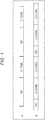
- a of Fig. 1 illustrates an example, as an exemplary configuration of the DVB-T2 signal containing the FEFs, where the FEF parts and the T2 frame parts are alternately constructed.
- B of Fig. 1 illustrates an example, as an exemplary configuration of the DVB-T2 signal containing the FEFs, where a set of the one FEF part followed by the two consecutive T2 frame parts is alternately constructed.
- reception devices of the respective techniques independently detect respective signals to receive.
- a reception device configured to receive the T2 frame and a reception device configured to receive the FEF independently detect the respective signals to receive.
- the T2 frame (T2 frame) is constituted by a P1 symbol, a P2 symbol, and data symbols (Date symbols) in this order from the top (left side).
- the P1 symbol and the P2 symbol located at the top of the T2 frame include transmission information about the signal.
- P1 signalling (signalling) in the P1 symbol includes an FFT size and a signal indicating whether the FEF is present with respect to the T2 frame serving as the desired signal.
- the P2 frame is configured so as to include L1-pre signalling (signalling) and L1-post signalling (signalling).
- the L1-pre signalling includes the number of data symbols and a guard interval ratio in the configuration.
- the L1-post signalling is configured so as to include, for example, Configurable, Dynaminc, Extension, CRC, and L1-padding (padding). This Configurable includes an FEF interval and FEF duration.
- T2 frame length FEF interval ⁇ data count ⁇ FFT size ⁇ guard interval ratio + P 1 length + P 2 length
- a receiver that receives the DVB-T2 signal containing the FEFs can recognize the presence of the FEF part and the duration thereof at a receiving side by acquiring these items of the information.
- the present technology is configured to stop reception processing during this part.
- the action of the receiver is configured to be turned off during the FEF part, while the action of the receiver is turned on solely during the T2 frame part.
- Fig. 5 is a block diagram illustrating an exemplary configuration of the reception device to which the present technology is applied.
- Data (signal) obtained by the time-division multiplexing of the T2 frame part and the FEF part in accordance with, for example, the DVB-T2 standard is transferred from a sender (not illustrated).
- This reception device receives the data obtained by the time-division multiplexing of the T2 frame part and the FEF part.
- the reception device 1 is configured so as to include an RF circuit 11, an analog to digital (A/D) circuit 12, and a demodulator 13.
- A/D analog to digital
- the RF circuit 11 is constituted by, for example, a tuner.
- the RF circuit 11 receives an RF signal of the data obtained by the time-division multiplexing of the T2 frame part and the FEF part to carry out predetermined signal processing thereon and then generates an intermediate frequency (IF) signal or a baseband (BB) signal according to a system.
- the RF circuit 11 supplies the generated IF signal or BB signal to the A/D circuit 12.
- the A/D circuit 12 converts analog data from the RF circuit 11, namely, the IF signal or BB signal to digital data and then outputs the converted digital data to the demodulator 13.
- the demodulator 13 is configured so as to include an orthogonal frequency division multiplexing (OFDM) signal demodulator 21, a P1 information decoding unit 22, an L1 information decoding unit 23, a data decoding unit 24, an FEF part measurement unit 25, and a module action control unit 26.
- OFDM orthogonal frequency division multiplexing
- the digital data from the A/D circuit 12 is input to the OFDM signal demodulator 21.
- the OFDM signal demodulator 21 carries out OFDM demodulation on the digital data to detect the position of P1 from the demodulated data and then supplies a time domain signal of P1 to the P1 information decoding unit 22.
- the OFDM signal demodulator 21 detects P2 from the demodulated data and then supplies a demodulator output signal for the position of P2 to the L1 information decoding unit 23.
- the OFDM signal demodulator 21 also outputs the demodulator output signal other than P1 and P2 to the data decoding unit 24 from among the demodulated data.
- the T2 frame length and the FEF length can be known from the FFT size and the signal indicating whether the FEF is present, in the P1 transmission information supplied from the P1 information decoding unit 22, and the number of the data symbols and a guard interval in L1 transmission information supplied from the L1 information decoding unit 23, as well as the FEF interval and the FEF duration.
- the OFDM signal demodulator 21 can find out the top of the frame and accordingly supplies timing information indicating the top of the frame to the FEF part measurement unit 25.
- the P1 information decoding unit 22 decodes the time domain signal of P1 from the OFDM signal demodulator 21 and then acquires the P1 transmission information (the FFT size and the signal indicating whether the FEF is present with respect to the T2 frame, which are included in P1 signalling). The P1 information decoding unit 22 supplies the acquired P1 transmission information to the OFDM signal demodulator 21 and the FEF part measurement unit 25.
- the L1 information decoding unit 23 decodes the demodulator output signal for the position of P2 from the OFDM signal demodulator 21 and then acquires the L1 transmission information (the number of the data symbols and the guard interval included in the L1-pre signalling and a signal indicating the FEF interval and the FEF duration, which is included in the L1-post signalling).
- the L1 information decoding unit 23 supplies the acquired L1 transmission information to the OFDM signal demodulator 21 and the FEF part measurement unit 25.
- the data decoding unit 24 decodes the demodulator output signal other than P1 and P2, namely, the data symbol to output to a latter stage (not illustrated) as demodulator output.
- the FEF part measurement unit 25 is a module of a constant action block and, on the basis of the timing information about the frame from the OFDM signal demodulator 21, the P1 transmission information from the P1 information decoding unit 22, and the L1 transmission information from the L1 information decoding unit 23, supplies, to the module action control unit 26, FEF part information indicating that the current frame is in the FEF part or in the T2 frame part.
- the module action control unit 26 is a module of the constant action block and, on the basis of the FEF part information from the EFE part measurement unit 25, controls an intermittent action block that works intermittently to turn off (stop) and on (restart), as indicated by dotted line arrows.
- the order of stopping and restarting respective modules of the intermittent action block is controlled by the module action control unit 26 and, for example, the control is performed in accordance with a temporal flow of data. Specifically, it is possible to give a stop at a time point when processing of data is completed for the first time in the T2 frame part.
- the intermittent action block is made up of the OFDM signal demodulator 21, the P1 information decoding unit 22, the L1 information decoding unit 23, and the data decoding unit 24 within the demodulator 13.
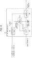
- Fig. 8 is a block diagram illustrating an exemplary configuration of the FEF part measurement unit 25.
- the FEF part measurement unit 25 is configured so as to include a sample count calculation unit 41, a reset comparator 42, a counter 43, and an FEF comparator 44.
- the FFT size and the signal indicating whether the FEF is present are input to the sample count calculation unit 41 from the P1 information decoding unit 22 as the P1 transmission information.
- the number of the data symbols, the guard interval, the signal indicating the FEF interval and the FEF duration are input to the sample count calculation unit 41 from the L1 information decoding unit 23 as the L1 transmission information.
- the sample count calculation unit 41 works out the number of samples corresponding to the FEF part (hereinafter, referred to as FEF sample count) and the number of samples corresponding to one period (hereinafter, referred to as one-period sample count) on the basis of the P1 transmission information and the L1 transmission information.
- the sample count calculation unit 41 supplies the one-period sample count to the reset comparator and supplies the FEF sample count to the FEF comparator 44.
- the reset comparator 42 compares a sample number within the frame from the counter 43 with the one-period sample count from the sample count calculation unit 41 and, when both the values match with each other, supplies a reset signal to the counter 43.
- the counter 43 starts counting on the basis of the timing information from the OFDM signal demodulator 21 indicating what point serves as the top of the frame. In addition, the counter 43 resets counting in line with the reset signal from the reset comparator 42.
- the counter 43 outputs the sample number within the frame representing a count number to the reset comparator 42 and the FEF comparator 44.
- the FEF comparator 44 compares the FEF sample count with the number of samples within the frame and, when the number of samples within the frame is equivalent to the FEF sample count, supplies the FEF part information indicating that the current sample is in the FEF part to the module action control unit 26. When the number of samples within the frame is not equivalent to the FEF sample count, the FEF comparator 44 supplies the FEF part information indicating that the current sample is in the T2 frame part to the module action control unit 26.
- the FEF comparator 44 supplies a fact that the current sample is in the T2 frame part to the module action control unit 26 as the FEF part information.
- an area between a line representing the FEF sample count and a line representing the one-period sample count denotes samples equivalent to the FEF sample count.
- the FEF comparator 44 judges that the current sample is in the FEF part and supplies the FEF part information indicating that the current sample is in the FEF part to the module action control unit 26.
- the reset comparator 42 determines that this point is the top of the T2 frame and then resets the counter 43. Accordingly, the sample number within the frame becomes zero.
- the FEF comparator 44 keeps the judgment that the current sample is in the T2 frame part until it is judged again from that time point that the sample number within the frame is equivalent to the FEF sample count and thus supplies the FEF part information indicating that the current sample is in the T2 frame part to the module action control unit 26.
- the module action control unit 26 transfers a signal to turn off control to the respective modules of the intermittent action block. Upon accepting the signal to turn off control, the respective modules of the intermittent action block shift to an OFF (stop) state.
- the module action control unit 26 transfers a signal to turn on control to the respective modules of the intermittent action block. Upon accepting the signal to turn on control, the respective modules of the intermittent action block shift to an ON (restart) state.
- reception processing by the reception device 1 will be described with reference to a flowchart in Fig. 10 .
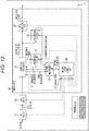
- the module action control unit 26 puts all the modules (the modules of the constant action block and the modules of the intermittent action block) into a working state as illustrated in Fig. 12 .
- the example in Fig. 12 illustrates that all the modules in the reception device 1 are blocks in the working state (i.e., working blocks).
- the module action control unit 26 sends the signal to turn on control to all the modules.
- the RF circuit 11 supplies the generated IF signal to the A/D circuit 12.
- the A/D circuit 12 converts analog data from the RF circuit 11, namely, the IF signal to digital data and then outputs the converted digital data to the OFDM signal demodulator 21.
- the OFDM signal demodulator 21 carries out the OFDM demodulation on the digital data to detect the position of P1 from the demodulated data and then supplies the time domain signal of P1 to the P1 information decoding unit 22.
- the P1 information decoding unit 22 decodes the time domain signal of P1 from the OFDM signal demodulator 21 to acquire the P1 transmission information.
- the P1 information decoding unit 22 supplies the acquired P1 transmission information to the OFDM signal demodulator 21 and the FEF part measurement unit 25.
- the OFDM signal demodulator 21 detects P2 from the demodulated data and then supplies the demodulator output signal for the position of P2 to the L1 information decoding unit 23.
- the L1 information decoding unit 23 decodes the demodulator output signal for the position of P2 from the OFDM signal demodulator 21 to acquire the L1 transmission information.
- the L1 information decoding unit 23 supplies the acquired L1 transmission information to the OFDM signal demodulator 21 and the FEF part measurement unit 25. This means that the respective modules of the intermittent action block stop working during the FEF part after the P1 information decoding unit 22 and the L1 information decoding unit 23 serving as members thereof acquire the transmission information regarding the FEF part.
- the FEF part measurement unit 25 carries out FEF part measurement processing on the basis of the timing information about the frame from the OFDM signal demodulator 21, the P1 transmission information from the P1 information decoding unit 22, and the L1 transmission information from the L1 information decoding unit 23. Details of this FEF part measurement processing will be described later with reference to Fig. 11 .
- the FEF part information indicating the FEF part or the T2 frame part is supplied to the module action control unit 26 through step S14.
- the module action control unit 26 judges whether the current sample is in the FEF part. When it is judged at step S15 that the current sample is in the FEF part, the processing proceeds to step S16. At step S16, the module action control unit 26 transfers the signal to turn off control to the respective modules of the intermittent action block. At step S17, the respective modules of the intermittent action block shift to the OFF (stop) state as indicated by stopping blocks (sections with hatching) illustrated with hatching in Fig. 13 .
- step S15 When it is judged at step S15 that the current sample is not in the FEF part, the processing proceeds to step S18.
- the module action control unit 26 transfers the signal to turn on control to the respective modules of the intermittent action block.
- the respective modules of the intermittent action block keep its states at step S11 described above or shift to the ON (working) state (the working blocks in Fig. 12 ) from the stopping blocks illustrated with hatching in Fig. 13 .
- the sample count calculation unit 41 acquires the P1 transmission information at step S31 and then acquires the L1 transmission information at step S32.
- the counter 43 determines a count starting position at step S33 on the basis of this timing information and then starts counting at step S34.
- the counter 43 supplies the count number to the reset comparator 42 and the FEF comparator 44 as the sample number within the frame.
- step S35 the FEF comparator 44 compares the FEF sample count with the number of samples within the frame to judge whether the number of samples within the frame is equivalent to the FEF sample count.
- step S35 the processing proceeds to step S36.
- the FEF comparator 44 supplies the FEF part information indicating that the current sample is in the FEF part to the module action control unit 26.
- the reset comparator 42 compares the sample number within the frame from the counter 43 with the one-period sample count from the sample count calculation unit 41 to judge whether the sample number within the frame matches the one-period sample count.
- step S37 When it is judged at step S37 that the sample number within the frame matches the one-period sample count, the processing proceeds to step S38.
- step S38 the counter 43 resets since the reset comparator 42 supplies the reset signal to the counter 43. Following this, the processing returns to step S34 and the processing subsequent thereto is repeated.
- the processing returns to step S34 and the processing subsequent thereto is repeated.
- step S35 when it is judged at step S35 that the number of samples within the frame is not equivalent to the FEF sample count, the processing proceeds to step S39.
- step S39 the FEF comparator 44 supplies the FEF part information indicating that the current sample is in the T2 frame part to the module action control unit 26. Thereafter, the processing returns to step S34 and the processing subsequent thereto is repeated.
- a certain part of the action of the reception device is configured to be turned off during the FEF part, while the certain part of the action of the reception device is turned on solely during the T2 frame part.
- Fig. 14 is a detailed block diagram of the RF circuit and the A/D circuit.
- the RF circuit 11 and the A/D circuit 12 are configured so as to include, for example, an RF filter 61, a gain variable RF amplifier 62, an RF filter 63, a mixer 64, a channel selection filter 65, a gain variable IF amplifier 66, a local oscillation circuit 67, an overload detector (distortion detector) 68, and an ADC 69.
- a ground-wave digital broadcasting signal received by an antenna is input to the RF filter 61.
- the RF filter 61 allows only the ground-wave digital broadcasting signal to pass.
- the gain variable RF amplifier 62 amplifies the signal that has passed through the RF filter 61 by a gain according to a reception frequency to supply to the RF filter 63.
- the RF filter 63 allows only a signal at the reception frequency to pass from among the signals amplified at the gain variable RF amplifier 62 and then supplies the signal that has passed therethrough to the mixer 64.
- the mixer 64 mixes an output signal from the RF filter 63 with a signal at a local frequency Flo supplied from the local oscillation circuit 67 and then supplies the IF signal obtained as a result thereof to the channel selection filter 65 and the overload detector 68.
- the channel selection filter 65 removes a disturbing signal at a frequency adjacent to an intermediate frequency.
- the gain variable IF amplifier 66 amplifies the IF signal after the removal by a predetermined gain to supply to the ADC 69.
- the overload detector 68 detects distortion in a transmission path and then outputs a result of the detection to the OFDM signal demodulator 21 at a latter stage.
- the ADC 69 converts the analog IF signal to digital data and then outputs the converted digital data to the OFDM signal demodulator 21 at a latter stage.
- the order of shutting down be as follows: the local oscillation circuit 67, the ADC 69, the gain variable IF amplifier 66, the channel selection filter 65, the overload detector 68, the mixer 64, and the gain variable RF amplifier 62.
- the order of starting up be as follows: the gain variable RF amplifier 62, the mixer 64, the overload detector 68, the channel selection filter 65, the gain variable IF amplifier 66, the ADC 69, and the local oscillation circuit 67.
- the RF circuit 11 and the A/D circuit 12 are stopped and restarted in the orders described above. With this, unnecessary radiation from the antenna can be suppressed.
- the RF circuit 11 and the A/D circuit 12 serving as the intermittent action block are stopped during the FEF part and then restarted.
- procedures mentioned above in Fig. 14 are used in shutting down and starting up in phases.
- ⁇ carrier frequency error indicated in Fig. 15 means that, when the X'tal frequency shifts, a frequency created from the X'tal frequency also shifts and an error thereof, specifically, the carrier frequency error also shifts.
- the demodulator 13 (OFDM signal demodulator 21) corrects the carrier frequency error and a down-conversion frequency error at a latter stage of the RF circuit and the A/D circuit.
- These frequency errors corrected by the demodulator 13 are usually assumed as 0 MHz as illustrated at the timing t01 when the FEF part starts.
- a shift of the oscillation frequency e.g., 1 MHz
- the original frequency is recovered because of changes in the transmission frequency. Nevertheless, the performance is deteriorated or the synchronization is lost for a certain period of time due to the aforementioned shift. In a serious case of a considerable shift, there is a risk of difficulties in receiving the signal.
- the demodulator 13 carries out compensation processing through handling by way of a first method to fourth method described below.
- the first method is configured such that, by assuming that an amount of this shift (e.g., 1 MHz) is known, the demodulator 13 traces a shift of the oscillation frequency (e.g., 1 MHz) at a timing t12 when the FEF part ends, by using a pattern of a variation curve corresponding to the amount of the shift (1 MHz, 0.5 MHz, 0 Mhz, or the like) irreversibly specified in advance.
- an amount of this shift e.g. 1 MHz
- the demodulator 13 traces a shift of the oscillation frequency (e.g., 1 MHz) at a timing t12 when the FEF part ends, by using a pattern of a variation curve corresponding to the amount of the shift (1 MHz, 0.5 MHz, 0 Mhz, or the like) irreversibly specified in advance.
- the demodulator 13 records variations (error detection value) in the crystal (X'tal) frequency ( ⁇ carrier frequency error) to keep as illustrated in Fig. 17 .
- the demodulator 13 corrects the shift of the oscillation frequency (e.g., 1 MHz) at a timing t22 when the FEF part ends, by using an inverse characteristic of the variations (error detection value) recorded at the immediately previous timing t20.
- the frequency error in the demodulator 13 is known to be slightly shifted and also there is a strong possibility of erroneous estimation due to a noise or the like. Accordingly, an amount equivalent to the error is usually configured not to be quickly implemented.
- the third method is configured such that, because the possibility of the shift of the oscillation frequency (e.g., 1 MHz) occurring at a timing t32 when the FEF part ends is known, the demodulator 13 quickly implements an amount equivalent to the error only immediately after that timing, by enhancing an error tracking characteristic. Note that, in this case, there is a risk of the deterioration of performance when the erroneous estimation is caused by a noise.
- the fourth method sets the startup of the RF circuit 11 from stopping (Sleep) earlier before a timing t52 when the FEF part ends (that is, sets the startup to a time point prior to a desired action start time by an amount of time required to make the temperature stable).
- This setting changes in temperature to the crystal (X'tal) frequency ( ⁇ carrier frequency error) of the local oscillation circuit 67 is made stable by the timing t52 when the T2 frame starts and the oscillation frequency is also put into a stable state.
- This fourth method is the simplest method but a power-off time is shortened.
- the module action control unit 26 it is possible for the module action control unit 26 to control the turning on/off of the RF circuit 11 and so on during the EFE part by using a certain time shift.
- the respective modules of the intermittent action block are stopped during the FEF part. As a consequence, the electric power consumption can be suppressed.
- the compensation processing for the frequency error is carried out when the analog circuit is stopped. As a consequence, an influence to the circuit due to changes in temperature can be suppressed.
- clock gating which holds standby electric power is used when the action is stopped as described above.
- power gating which turns off the main power as well may be used.
- all of the modules of the intermittent action block have been described as intermittently working. However, at least one of them may be configured to intermittently work. Meanwhile, as described above, the order of the control to stop the intermittent action block can be in accordance with a flow of data but is not restricted thereto. For example, a block having higher electric power consumption may be configured to be stopped earlier.
- Fig. 20 is a block diagram illustrating an exemplary hardware configuration of a computer that carries out the aforementioned series of the processing using a program.
- a central processing unit (CPU) 401 a read only memory (ROM) 402, and a random access memory (RAM) 403 are interconnected through a bus 404.
- CPU central processing unit
- ROM read only memory
- RAM random access memory
- an input/output interface 405 is connected to the bus 404.
- An input unit 406, an output unit 407, a storage unit 408, a communication unit 409, and a drive 410 are connected to the input/output interface 405.
- the input unit 406 includes a keyboard, a mouse, and a microphone.
- the output unit 407 includes a display and a speaker.
- the storage unit 408 includes a hard disk and a non-volatile memory.
- the communication unit 409 includes a network interface.
- the drive 410 drives a removable recording medium 411 such as a magnetic disk, an optical disc, a magneto-optical disk, or a semiconductor memory.
- the aforementioned series of the processing is carried out in such a manner that the CPU 401 loads a program stored in the storage unit 408 to the RAM 403 via the input/output interface 405 and the bus 404 to execute.
- the program executed by the computer (CPU 401) can be provided by being recorded in the removable recording medium 411 serving as a package medium or the like.
- the program can be provided via a wired or wireless transmission medium such as a local area network, the Internet, or digital broadcasting.
- the program can be installed to the storage unit 408 via the input/output interface 405 by mounting the removable recording medium 411 in the drive 410.
- the program can be also installed to the storage unit 408 via a wired or wireless transmission medium when received by the communication unit 409.
- the program can be installed to the ROM 402 or the storage unit 408 in advance.
- the program executed by the computer may be a program in which the processing is carried out along the time series in accordance with the order described in the present description, or alternatively, may be a program in which the processing is carried out in parallel or at a necessary timing, for example, when called.
- system used in the present description implies an entire device configured by a plurality of devices, blocks, means and so on.
- a configuration described as one device may be divided so as to be configured as a plurality of devices (or processing units).
- a configuration described as a plurality of devices (or processing units) may be integrated so as to be configured as one device (or a processing unit).
- a configuration other than those described above may be employed to be added to the configurations of the respective devices (or the respective processing units).
- a portion of a certain device (or a certain processing unit) may be configured to be included in the configuration of another device (or another processing unit) as long as the configuration or the action of the system as a whole is maintained substantially unchanged. That is, the present technology is not limited to the aforementioned embodiments and various modifications can be made without departing from the scope of the present technology.
Landscapes
- Engineering & Computer Science (AREA)
- Computer Networks & Wireless Communication (AREA)
- Signal Processing (AREA)
- Circuits Of Receivers In General (AREA)
Abstract
Description
- The present disclosure relates to a reception device and a reception method. In particular, the disclosure relates to a reception device and a reception method that achieve reduction in electric power consumption while data separated in a time direction is partially received.
- According to the definition in a digital video broadcasting-terrestrial (DVB-T) 2 standard, data is transmitted in units of transmission frames referred to as T2 frames serving as desired signals (refer to Non-patent Document 1). Additionally, there is a mode in the DVB-T2 in which time-division multiplexing is applied to a signal called a future extension frame (FEF) having a structure different from that of the aforementioned T2 frame, on top of the T2 frame when transmitted.
- Typically, when receiving a signal sent after being constructed by multiplexing signals according to a plurality of techniques having structures different from one another, reception devices of the respective techniques independently detect respective signals to receive. Similarly in the DVB-T2, for example, a reception device configured to receive the T2 frame and a reception device configured to receive the FEF independently detect the respective signals to receive.
- Specifically, P1 and P2 symbols in the T2 frame include transmission information about a signal, including an FFTSIZE, a data length, a guard interval ratio, the number of times of repetitions of the T2 frame, whether the FEF is present, an FEF part length, and so on with respect to the desired signal. Accordingly, a receiving side can recognize the presence of the FEF part and duration thereof by acquiring these items of the information.
- Incidentally, a technology has been known in which one of thirteen segments alone is received during the reception of one segment data in an ISDB-T to reduce electric power consumption of a reception device that receives this data.
- Non-patent Document 1: ETSI EN 302 755 V1.3.1, Frame structure channel coding and modulation for a second generation digital terrestrial television broadcasting system (DVB-T2) 2012, 04, the home page of the DVB, [searched on October 9, 2014], the Internet <URL: http://www.dvb.org/technology/standards/dvb-t2>
- However, the segment in the ISDB-T is separated in a frequency direction and thus needs to be received continuously in the time direction. For this reason, this technology has not contributed to reduction in electric power consumption when the FEF in the DVB-T2 is present.
- Accordingly, it is required to achieve low electric power consumption in a reception device while data separated in the time direction as in the DVB-T2 is partially received.
- The present disclosure has been made by taking such a situation into account and an object thereof is to achieve lower electric power necessary while data separated in a time direction is partially received.
- A reception device according to an aspect of the present disclosure includes an intermittent action block that works solely during a first frame part when receiving data obtained by time-division multiplexing of the first frame part and a second frame part, which second frame has a structure different from a structure of the first frame, and a constant action block that constantly monitors the first frame part and the second frame part and controls an action of the intermittent action block.
- The intermittent action block includes an information acquisition unit configured to acquire transmission information regarding the first frame part and the second frame part and is able to work solely during the first frame part after the information acquisition unit acquires the transmission information regarding the first frame part and the second frame part.
- The first frame part is a T2 frame part and the second frame part is an FEF part.
- The constant action block is able to carry out control of stopping and restarting the action of the intermittent action block in accordance with a temporal flow of the data.
- The intermittent action block is able to include an RF circuit and an A/D converter.
- The constant action block is able to stop and restart actions of the RF circuit and the A/D converter in phases.
- The constant action block is able to carry out control of stopping the actions of the RF circuit and the A/D converter in the order of an oscillation circuit, the A/D converter, a gain variable amplifier, a channel selection filter, a distortion detector, a mixer, and a gain variable amplifier, which constitute the RF circuit and the A/D converter.
- The constant action block is able to carry out control of restarting the actions of the RF circuit and the A/D converter in the order of a gain variable amplifier, a mixer, a distortion detector, a channel selection filter, a gain variable amplifier, the A/D converter, and an oscillation circuit, which constitute the RF circuit and the A/D converter.
- A compensation unit can be further provided, which compensation unit compensates a change in a reception state due to temperature characteristics of the RF circuit and the A/D converter serving as analog circuits when the actions of the RF circuit and the A/D converter are restarted after being stopped, by using signals from the RF circuit and the A/D converter.
- The compensation unit is a demodulator that corrects sampling frequency and down-conversion frequency errors due to a change in an oscillation frequency of an oscillation circuit included in the RF circuit and the A/D converter.
- The demodulator is able to correct the sampling frequency and down-conversion frequency errors by using a pattern fixedly set.
- The demodulator is able to record an error detection value for the sampling frequency and down-conversion frequency errors and make a correction on the basis of the error detection value recorded at an immediately previous time.
- The demodulator is able to correct the sampling frequency and down-conversion frequency errors by enhancing an error tracking characteristic for a time period until the temperature characteristics become stable.
- The demodulator is able to correct the sampling frequency and down-conversion frequency errors by achieving temperature stability earlier in such a manner as to restart the actions of the RF circuit and the A/D converter from a time point prior to a desired action start time thereof by an amount of time required to make the temperature stable.
- The constant action block is able to carry out control of stopping the action of the intermittent action block through clock gating.
- The constant action block is able to carry out control of stopping the action of the intermittent action block through power gating.
- In a reception method according to an aspect of the present disclosure, an intermittent action block of a reception device works solely during a first frame part when receiving data obtained by time-division multiplexing of the first frame part and a second frame part, which second frame has a structure different from a structure of the first frame, and a constant action block of the reception device constantly monitors the first frame part and the second frame part and controls an action of the intermittent action block.
- According to an aspect of the present disclosure, when receiving data obtained by the time-division multiplexing of the first frame part and the second frame part, which second frame has a structure different from a structure of the first frame, the intermittent action block works solely during the first frame part. Additionally, the constant action block of the reception device constantly monitors the first frame part and the second frame part and controls the action of the intermittent action block.
- According to the present technology, data separated in the time direction can be partially received. In particular, according to the present technology, electric power consumption while data separated in the time direction is partially received can be reduced.
- Note that the effects described in the present description merely serve as examples and the effects of the present technology are not limited to the effects described in the present description. There may be an additional effect as well.
-
-
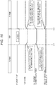
Fig. 1 is a diagram illustrating an exemplary configuration of a DVB-T2 signal containing FEFs. -
Fig. 2 is a diagram illustrating an example of an exemplary configuration of a T2 frame. -
Fig. 3 is a diagram for explaining a frame length. -
Fig. 4 is a diagram illustrating a relationship between an action of a reception device and electric power consumption. -
Fig. 5 is a block diagram illustrating an exemplary configuration of a reception device to which the present technology is applied. -
Fig. 6 is a block diagram illustrating examples of a constant action block and an intermittent action block in the reception device. -
Fig. 7 is a block diagram illustrating other examples of the constant action block and the intermittent action block in the reception device. -
Fig. 8 is a block diagram illustrating an exemplary configuration of an FEF part measurement unit. -
Fig. 9 is a diagram for explaining a measurement method for an FEF part. -
Fig. 10 is a flowchart for explaining reception processing. -
Fig. 11 is a flowchart for explaining exemplary FEF part measurement processing. -
Fig. 12 is a block diagram illustrating working blocks that are working in the reception device. -
Fig. 13 is a block diagram illustrating stopping blocks that are stopped in the reception device. -
Fig. 14 is a detailed block diagram of an RF circuit and an A/D circuit. -
Fig. 15 is a diagram for explaining a case where a frequency error occurs due to changes in temperature. -
Fig. 16 is a diagram for explaining a first method for handling a frequency error due to changes in temperature. -
Fig. 17 is a diagram for explaining a second method for handling a frequency error due to changes in temperature. -
Fig. 18 is a diagram for explaining a third method for handling a frequency error due to changes in temperature. -
Fig. 19 is a diagram for explaining a fourth method for handling a frequency error due to changes in temperature. -
Fig. 20 is a diagram illustrating an exemplary configuration of a computer. - Modes for carrying out the present disclosure (hereinafter, referred to as embodiments) will be described below. Note that the description will be given in the following order.
-
- 1. First Embodiment (Example of Reception Device according to Present Technology)
- 2. Second Embodiment (Example of Compensation Processing according to Present Technology)
- 3. Third Embodiment (Example of Computer)
- According to the definition in a digital video broadcasting-terrestrial (DVB-T) 2 standard, data is transmitted in units of transmission frames referred to as T2 frames serving as desired signals. Additionally, there is a mode in the DVB-T2 in which time-division multiplexing is applied to a signal called a future extension frame (FEF) having a structure different from that of the aforementioned T2 frame, on top of the T2 frame when transmitted. For example, the desired signal desired by a user is input to a T2 frame part. In contrast to this, although it is still unknown for the time being what will be input to an FEF part, a signal of one segment data or the like will be input thereto in the future.
- For example, A of
Fig. 1 illustrates an example, as an exemplary configuration of the DVB-T2 signal containing the FEFs, where the FEF parts and the T2 frame parts are alternately constructed. In addition, B ofFig. 1 illustrates an example, as an exemplary configuration of the DVB-T2 signal containing the FEFs, where a set of the one FEF part followed by the two consecutive T2 frame parts is alternately constructed. - Typically, when receiving a signal sent after being constructed by multiplexing signals according to a plurality of techniques having structures different from one another, reception devices of the respective techniques independently detect respective signals to receive. Similarly in the DVB-T2, for example, a reception device configured to receive the T2 frame and a reception device configured to receive the FEF independently detect the respective signals to receive.
- Specifically, as illustrated in
Fig. 2 , the T2 frame (T2 frame) is constituted by a P1 symbol, a P2 symbol, and data symbols (Date symbols) in this order from the top (left side). - The P1 symbol and the P2 symbol located at the top of the T2 frame include transmission information about the signal. For example, P1 signalling (signalling) in the P1 symbol includes an FFT size and a signal indicating whether the FEF is present with respect to the T2 frame serving as the desired signal.
- Meanwhile, the P2 frame is configured so as to include L1-pre signalling (signalling) and L1-post signalling (signalling). The L1-pre signalling includes the number of data symbols and a guard interval ratio in the configuration. The L1-post signalling is configured so as to include, for example, Configurable, Dynaminc, Extension, CRC, and L1-padding (padding). This Configurable includes an FEF interval and FEF duration.
- As illustrated in A of
Fig. 3 and B ofFig. 3 , a T2 frame length can be settled from the above-described transmission information about the signal as follows:
- P1 length = 2048 samples (fixed)
- P2 length = uniquely determined by the FFT size
- As described thus far, a receiver that receives the DVB-T2 signal containing the FEFs can recognize the presence of the FEF part and the duration thereof at a receiving side by acquiring these items of the information.
- Here, when the T2 frame is a signal desired by the user (desired signal), a signal in such an FEF part does not need to be received because this signal is not the desired signal. By considering this, the present technology is configured to stop reception processing during this part.
- As illustrated on the upper side of
Fig. 4 , when data obtained by the time-division multiplexing of the T2 frame part and the FEF part is received, the action of the receiver that receives this data has been constantly turned on in the past, resulting in higher electric power consumption. - In contrast to this, as illustrated on the lower side of
Fig. 4 , the action of the receiver is configured to be turned off during the FEF part, while the action of the receiver is turned on solely during the T2 frame part. With this, although the electric power consumption during the T2 frame part does not change, the electric power consumption during the FEF part decreases. Consequently, the electric power consumption can be reduced, compared to a case where the action of the receiver is constantly turned on. -
Fig. 5 is a block diagram illustrating an exemplary configuration of the reception device to which the present technology is applied. Data (signal) obtained by the time-division multiplexing of the T2 frame part and the FEF part in accordance with, for example, the DVB-T2 standard is transferred from a sender (not illustrated). This reception device receives the data obtained by the time-division multiplexing of the T2 frame part and the FEF part. - In the example in
Fig. 5 , thereception device 1 is configured so as to include anRF circuit 11, an analog to digital (A/D)circuit 12, and ademodulator 13. - The
RF circuit 11 is constituted by, for example, a tuner. TheRF circuit 11 receives an RF signal of the data obtained by the time-division multiplexing of the T2 frame part and the FEF part to carry out predetermined signal processing thereon and then generates an intermediate frequency (IF) signal or a baseband (BB) signal according to a system. TheRF circuit 11 supplies the generated IF signal or BB signal to the A/D circuit 12. - The A/
D circuit 12 converts analog data from theRF circuit 11, namely, the IF signal or BB signal to digital data and then outputs the converted digital data to thedemodulator 13. - The
demodulator 13 is configured so as to include an orthogonal frequency division multiplexing (OFDM)signal demodulator 21, a P1information decoding unit 22, an L1information decoding unit 23, adata decoding unit 24, an FEFpart measurement unit 25, and a moduleaction control unit 26. - The digital data from the A/
D circuit 12 is input to theOFDM signal demodulator 21. TheOFDM signal demodulator 21 carries out OFDM demodulation on the digital data to detect the position of P1 from the demodulated data and then supplies a time domain signal of P1 to the P1information decoding unit 22. - Because the duration of P2 is uniquely defined from the FFT size in P1 transmission information supplied from the P1
information decoding unit 22, theOFDM signal demodulator 21 detects P2 from the demodulated data and then supplies a demodulator output signal for the position of P2 to the L1information decoding unit 23. TheOFDM signal demodulator 21 also outputs the demodulator output signal other than P1 and P2 to thedata decoding unit 24 from among the demodulated data. - As described earlier with reference to A of
Fig. 3 and B ofFig. 3 , the T2 frame length and the FEF length can be known from the FFT size and the signal indicating whether the FEF is present, in the P1 transmission information supplied from the P1information decoding unit 22, and the number of the data symbols and a guard interval in L1 transmission information supplied from the L1information decoding unit 23, as well as the FEF interval and the FEF duration. With this, theOFDM signal demodulator 21 can find out the top of the frame and accordingly supplies timing information indicating the top of the frame to the FEFpart measurement unit 25. - The P1
information decoding unit 22 decodes the time domain signal of P1 from theOFDM signal demodulator 21 and then acquires the P1 transmission information (the FFT size and the signal indicating whether the FEF is present with respect to the T2 frame, which are included in P1 signalling). The P1information decoding unit 22 supplies the acquired P1 transmission information to theOFDM signal demodulator 21 and the FEFpart measurement unit 25. - The L1
information decoding unit 23 decodes the demodulator output signal for the position of P2 from theOFDM signal demodulator 21 and then acquires the L1 transmission information (the number of the data symbols and the guard interval included in the L1-pre signalling and a signal indicating the FEF interval and the FEF duration, which is included in the L1-post signalling). The L1information decoding unit 23 supplies the acquired L1 transmission information to theOFDM signal demodulator 21 and the FEFpart measurement unit 25. - The
data decoding unit 24 decodes the demodulator output signal other than P1 and P2, namely, the data symbol to output to a latter stage (not illustrated) as demodulator output. - The FEF
part measurement unit 25 is a module of a constant action block and, on the basis of the timing information about the frame from theOFDM signal demodulator 21, the P1 transmission information from the P1information decoding unit 22, and the L1 transmission information from the L1information decoding unit 23, supplies, to the moduleaction control unit 26, FEF part information indicating that the current frame is in the FEF part or in the T2 frame part. - The module
action control unit 26 is a module of the constant action block and, on the basis of the FEF part information from the EFEpart measurement unit 25, controls an intermittent action block that works intermittently to turn off (stop) and on (restart), as indicated by dotted line arrows. In addition, the order of stopping and restarting respective modules of the intermittent action block is controlled by the moduleaction control unit 26 and, for example, the control is performed in accordance with a temporal flow of data. Specifically, it is possible to give a stop at a time point when processing of data is completed for the first time in the T2 frame part. - Here, respective modules of the intermittent action block are illustrated with hatching in the examples in
Fig. 6 andFig. 7 . In the case of the example inFig. 6 , the intermittent action block is made up of theOFDM signal demodulator 21, the P1information decoding unit 22, the L1information decoding unit 23, and thedata decoding unit 24 within thedemodulator 13. - In contrast to this, in the case of the example in
Fig. 7 , not only the members within thedemodulator 13 illustrated inFig. 6 but also theRF circuit 11 and the A/D circuit 12 serving as analog circuits at the outside of thedemodulator 13 are included in the configuration of the intermittent action block. -
Fig. 8 is a block diagram illustrating an exemplary configuration of the FEFpart measurement unit 25. - In the example in
Fig. 8 , the FEFpart measurement unit 25 is configured so as to include a samplecount calculation unit 41, areset comparator 42, acounter 43, and anFEF comparator 44. - For example, the FFT size and the signal indicating whether the FEF is present are input to the sample
count calculation unit 41 from the P1information decoding unit 22 as the P1 transmission information. The number of the data symbols, the guard interval, the signal indicating the FEF interval and the FEF duration are input to the samplecount calculation unit 41 from the L1information decoding unit 23 as the L1 transmission information. - The sample
count calculation unit 41 works out the number of samples corresponding to the FEF part (hereinafter, referred to as FEF sample count) and the number of samples corresponding to one period (hereinafter, referred to as one-period sample count) on the basis of the P1 transmission information and the L1 transmission information. The samplecount calculation unit 41 supplies the one-period sample count to the reset comparator and supplies the FEF sample count to theFEF comparator 44. - The
reset comparator 42 compares a sample number within the frame from thecounter 43 with the one-period sample count from the samplecount calculation unit 41 and, when both the values match with each other, supplies a reset signal to thecounter 43. - The counter 43 starts counting on the basis of the timing information from the
OFDM signal demodulator 21 indicating what point serves as the top of the frame. In addition, thecounter 43 resets counting in line with the reset signal from thereset comparator 42. - The
counter 43 outputs the sample number within the frame representing a count number to thereset comparator 42 and theFEF comparator 44. - The
FEF comparator 44 compares the FEF sample count with the number of samples within the frame and, when the number of samples within the frame is equivalent to the FEF sample count, supplies the FEF part information indicating that the current sample is in the FEF part to the moduleaction control unit 26. When the number of samples within the frame is not equivalent to the FEF sample count, theFEF comparator 44 supplies the FEF part information indicating that the current sample is in the T2 frame part to the moduleaction control unit 26. - Once the
counter 43 is reset and then, the number of samples within the frame becomes one, theFEF comparator 44 supplies a fact that the current sample is in the T2 frame part to the moduleaction control unit 26 as the FEF part information. - That is, in the example in
Fig. 9 , an area between a line representing the FEF sample count and a line representing the one-period sample count denotes samples equivalent to the FEF sample count. - As illustrated in
Fig. 9 , while the sample number within the frame is equivalent to the FEF sample count, theFEF comparator 44 judges that the current sample is in the FEF part and supplies the FEF part information indicating that the current sample is in the FEF part to the moduleaction control unit 26. When the sample number within the frame matches the one-period sample count, thereset comparator 42 determines that this point is the top of the T2 frame and then resets thecounter 43. Accordingly, the sample number within the frame becomes zero. As a consequence, theFEF comparator 44 keeps the judgment that the current sample is in the T2 frame part until it is judged again from that time point that the sample number within the frame is equivalent to the FEF sample count and thus supplies the FEF part information indicating that the current sample is in the T2 frame part to the moduleaction control unit 26. - When the FEF part information indicating that the current sample is in the FEF part is given to the module
action control unit 26, the moduleaction control unit 26 transfers a signal to turn off control to the respective modules of the intermittent action block. Upon accepting the signal to turn off control, the respective modules of the intermittent action block shift to an OFF (stop) state. - When the FEF part information indicating that the current sample is in the T2 frame part is given to the module
action control unit 26, the moduleaction control unit 26 transfers a signal to turn on control to the respective modules of the intermittent action block. Upon accepting the signal to turn on control, the respective modules of the intermittent action block shift to an ON (restart) state. - Next, reception processing by the
reception device 1 will be described with reference to a flowchart inFig. 10 . - At step S11, the module
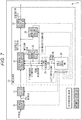
action control unit 26 puts all the modules (the modules of the constant action block and the modules of the intermittent action block) into a working state as illustrated inFig. 12 . The example inFig. 12 illustrates that all the modules in thereception device 1 are blocks in the working state (i.e., working blocks). - Specifically, the module
action control unit 26 sends the signal to turn on control to all the modules. - All the modules shift to the working state in response to this, while the
RF circuit 11 receives the RF signal of the data obtained by the time-division multiplexing of the T2 frame part and the FEF part to carry out predetermined signal processing thereon and then generates, for example, the IF signal. TheRF circuit 11 supplies the generated IF signal to the A/D circuit 12. - The A/
D circuit 12 converts analog data from theRF circuit 11, namely, the IF signal to digital data and then outputs the converted digital data to theOFDM signal demodulator 21. TheOFDM signal demodulator 21 carries out the OFDM demodulation on the digital data to detect the position of P1 from the demodulated data and then supplies the time domain signal of P1 to the P1information decoding unit 22. In response to this, at step S12, the P1information decoding unit 22 decodes the time domain signal of P1 from theOFDM signal demodulator 21 to acquire the P1 transmission information. The P1information decoding unit 22 supplies the acquired P1 transmission information to theOFDM signal demodulator 21 and the FEFpart measurement unit 25. - The
OFDM signal demodulator 21 detects P2 from the demodulated data and then supplies the demodulator output signal for the position of P2 to the L1information decoding unit 23. In response to this, at step S13, the L1information decoding unit 23 decodes the demodulator output signal for the position of P2 from theOFDM signal demodulator 21 to acquire the L1 transmission information. The L1information decoding unit 23 supplies the acquired L1 transmission information to theOFDM signal demodulator 21 and the FEFpart measurement unit 25. This means that the respective modules of the intermittent action block stop working during the FEF part after the P1information decoding unit 22 and the L1information decoding unit 23 serving as members thereof acquire the transmission information regarding the FEF part. - At step S14, the FEF
part measurement unit 25 carries out FEF part measurement processing on the basis of the timing information about the frame from theOFDM signal demodulator 21, the P1 transmission information from the P1information decoding unit 22, and the L1 transmission information from the L1information decoding unit 23. Details of this FEF part measurement processing will be described later with reference toFig. 11 . - The FEF part information indicating the FEF part or the T2 frame part is supplied to the module
action control unit 26 through step S14. - At step S15, the module
action control unit 26 judges whether the current sample is in the FEF part. When it is judged at step S15 that the current sample is in the FEF part, the processing proceeds to step S16. At step S16, the moduleaction control unit 26 transfers the signal to turn off control to the respective modules of the intermittent action block. At step S17, the respective modules of the intermittent action block shift to the OFF (stop) state as indicated by stopping blocks (sections with hatching) illustrated with hatching inFig. 13 . - When it is judged at step S15 that the current sample is not in the FEF part, the processing proceeds to step S18. At step S18, the module
action control unit 26 transfers the signal to turn on control to the respective modules of the intermittent action block. At step S19, the respective modules of the intermittent action block keep its states at step S11 described above or shift to the ON (working) state (the working blocks inFig. 12 ) from the stopping blocks illustrated with hatching inFig. 13 . - Next, FEF part measurement processing at step S14 in
Fig. 10 will be described with reference to a flowchart inFig. 11 . - The sample
count calculation unit 41 acquires the P1 transmission information at step S31 and then acquires the L1 transmission information at step S32. - After the timing information indicating what point serves as the top of the frame is transferred from the
OFDM signal demodulator 21, thecounter 43 determines a count starting position at step S33 on the basis of this timing information and then starts counting at step S34. Thecounter 43 supplies the count number to thereset comparator 42 and theFEF comparator 44 as the sample number within the frame. - At step S35, the
FEF comparator 44 compares the FEF sample count with the number of samples within the frame to judge whether the number of samples within the frame is equivalent to the FEF sample count. When it is judged at step S35 that the number of samples within the frame is equivalent to the FEF sample count, the processing proceeds to step S36. - At step S36, the
FEF comparator 44 supplies the FEF part information indicating that the current sample is in the FEF part to the moduleaction control unit 26. - At step S37, the
reset comparator 42 compares the sample number within the frame from thecounter 43 with the one-period sample count from the samplecount calculation unit 41 to judge whether the sample number within the frame matches the one-period sample count. - When it is judged at step S37 that the sample number within the frame matches the one-period sample count, the processing proceeds to step S38. At step S38, the
counter 43 resets since thereset comparator 42 supplies the reset signal to thecounter 43. Following this, the processing returns to step S34 and the processing subsequent thereto is repeated. When it is judged at step S37 that the sample number within the frame does not match the one-period sample count, the processing returns to step S34 and the processing subsequent thereto is repeated. - On the other hand, when it is judged at step S35 that the number of samples within the frame is not equivalent to the FEF sample count, the processing proceeds to step S39. At step S39, the
FEF comparator 44 supplies the FEF part information indicating that the current sample is in the T2 frame part to the moduleaction control unit 26. Thereafter, the processing returns to step S34 and the processing subsequent thereto is repeated. - As described thus far, a certain part of the action of the reception device is configured to be turned off during the FEF part, while the certain part of the action of the reception device is turned on solely during the T2 frame part. With this, although the electric power consumption during the T2 frame part does not change, the electric power consumption during the FEF part decreases. Consequently, the electric power consumption can be reduced, compared to a case where the action of the reception device is constantly turned on.
-
Fig. 14 is a detailed block diagram of the RF circuit and the A/D circuit. - The
RF circuit 11 and the A/D circuit 12 are configured so as to include, for example, anRF filter 61, a gainvariable RF amplifier 62, anRF filter 63, amixer 64, achannel selection filter 65, a gain variable IFamplifier 66, alocal oscillation circuit 67, an overload detector (distortion detector) 68, and anADC 69. - A ground-wave digital broadcasting signal received by an antenna (not illustrated) is input to the
RF filter 61. TheRF filter 61 allows only the ground-wave digital broadcasting signal to pass. The gainvariable RF amplifier 62 amplifies the signal that has passed through theRF filter 61 by a gain according to a reception frequency to supply to theRF filter 63. - The
RF filter 63 allows only a signal at the reception frequency to pass from among the signals amplified at the gainvariable RF amplifier 62 and then supplies the signal that has passed therethrough to themixer 64. Themixer 64 mixes an output signal from theRF filter 63 with a signal at a local frequency Flo supplied from thelocal oscillation circuit 67 and then supplies the IF signal obtained as a result thereof to thechannel selection filter 65 and theoverload detector 68. - The
channel selection filter 65 removes a disturbing signal at a frequency adjacent to an intermediate frequency. The gain variable IFamplifier 66 amplifies the IF signal after the removal by a predetermined gain to supply to theADC 69. Theoverload detector 68 detects distortion in a transmission path and then outputs a result of the detection to theOFDM signal demodulator 21 at a latter stage. TheADC 69 converts the analog IF signal to digital data and then outputs the converted digital data to theOFDM signal demodulator 21 at a latter stage. - In the
RF circuit 11 and the A/D circuit 12 configured as described above, it is desirable that the order of shutting down be as follows: thelocal oscillation circuit 67, theADC 69, the gain variable IFamplifier 66, thechannel selection filter 65, theoverload detector 68, themixer 64, and the gainvariable RF amplifier 62. - Conversely, it is desirable that the order of starting up be as follows: the gain
variable RF amplifier 62, themixer 64, theoverload detector 68, thechannel selection filter 65, the gain variable IFamplifier 66, theADC 69, and thelocal oscillation circuit 67. - The
RF circuit 11 and the A/D circuit 12 are stopped and restarted in the orders described above. With this, unnecessary radiation from the antenna can be suppressed. - As described above, in the
reception device 1 illustrated inFig. 7 , theRF circuit 11 and the A/D circuit 12 serving as the intermittent action block are stopped during the FEF part and then restarted. At this time, procedures mentioned above inFig. 14 are used in shutting down and starting up in phases. - Next, an influence to the
reception device 1 due to turning on/off of the RF circuit will be described with reference toFig. 15 to Fig. 19 . Note that the RF circuit in the drawings is assumed to include the A/D circuit. - As illustrated in
Fig. 15 at a timing t01 when the FEF part starts, when theRF circuit 11 is stopped (sleep) in the FEF part, the heat generation falls and the temperature of thereception device 1 becomes lower than the temperature during working. Meanwhile, as illustrated at a timing t02 when the FEF part ends, theRF circuit 11 restarts once the T2 frame period starts and accordingly, the heat generation rises, while the temperature of thereception device 1 becomes higher than the temperature during stopping. - As a consequence of this, in regard to a sampling frequency of the
local oscillation circuit 67, namely, a crystal (X'tal) frequency, an oscillation frequency varies at the timing t01 and the timing t02 depending on changes in the temperature. Note that "≈ carrier frequency error" indicated inFig. 15 means that, when the X'tal frequency shifts, a frequency created from the X'tal frequency also shifts and an error thereof, specifically, the carrier frequency error also shifts. - Subsequently, the demodulator 13 (OFDM signal demodulator 21) corrects the carrier frequency error and a down-conversion frequency error at a latter stage of the RF circuit and the A/D circuit. These frequency errors corrected by the
demodulator 13 are usually assumed as 0 MHz as illustrated at the timing t01 when the FEF part starts. In this situation, a shift of the oscillation frequency (e.g., 1 MHz) is discovered at the timing t02 when the FEF part ends and tracing this shift is attempted. However, the original frequency is recovered because of changes in the transmission frequency. Nevertheless, the performance is deteriorated or the synchronization is lost for a certain period of time due to the aforementioned shift. In a serious case of a considerable shift, there is a risk of difficulties in receiving the signal. - For a solution to this, the demodulator 13 carries out compensation processing through handling by way of a first method to fourth method described below.
- For example, as illustrated in
Fig. 16 , the first method is configured such that, by assuming that an amount of this shift (e.g., 1 MHz) is known, thedemodulator 13 traces a shift of the oscillation frequency (e.g., 1 MHz) at a timing t12 when the FEF part ends, by using a pattern of a variation curve corresponding to the amount of the shift (1 MHz, 0.5 MHz, 0 Mhz, or the like) irreversibly specified in advance. As a consequence, the generation of the shift as mentioned above inFig. 15 can be suppressed. - Next, in the second method, although the shift is generated in the frequency error corrected by the
demodulator 13 at a timing t20 when an immediately previous FEF part ends, the demodulator 13 records variations (error detection value) in the crystal (X'tal) frequency (≈ carrier frequency error) to keep as illustrated inFig. 17 . - As illustrated at a timing t21 when the FEF part starts, a usual value is assumed as 0 MHz. In this situation, the
demodulator 13 corrects the shift of the oscillation frequency (e.g., 1 MHz) at a timing t22 when the FEF part ends, by using an inverse characteristic of the variations (error detection value) recorded at the immediately previous timing t20. - Meanwhile, the frequency error in the
demodulator 13 is known to be slightly shifted and also there is a strong possibility of erroneous estimation due to a noise or the like. Accordingly, an amount equivalent to the error is usually configured not to be quickly implemented. In this situation, the third method is configured such that, because the possibility of the shift of the oscillation frequency (e.g., 1 MHz) occurring at a timing t32 when the FEF part ends is known, thedemodulator 13 quickly implements an amount equivalent to the error only immediately after that timing, by enhancing an error tracking characteristic. Note that, in this case, there is a risk of the deterioration of performance when the erroneous estimation is caused by a noise. - As illustrated in
Fig. 19 , the fourth method sets the startup of theRF circuit 11 from stopping (Sleep) earlier before a timing t52 when the FEF part ends (that is, sets the startup to a time point prior to a desired action start time by an amount of time required to make the temperature stable). With this setting, changes in temperature to the crystal (X'tal) frequency (≈ carrier frequency error) of thelocal oscillation circuit 67 is made stable by the timing t52 when the T2 frame starts and the oscillation frequency is also put into a stable state. - As a consequence, the
demodulator 13 does not notice the shift at the timing t52 when the FEF part ends and thus can continue the action as it is. This fourth method is the simplest method but a power-off time is shortened. - Additionally, in the example in
Fig. 19 , it is possible for the moduleaction control unit 26 to control the turning on/off of theRF circuit 11 and so on during the EFE part by using a certain time shift. - As described thus far, in the present technology, the respective modules of the intermittent action block are stopped during the FEF part. As a consequence, the electric power consumption can be suppressed.
- Furthermore, in the present technology, the compensation processing for the frequency error is carried out when the analog circuit is stopped. As a consequence, an influence to the circuit due to changes in temperature can be suppressed.
- Note that clock gating which holds standby electric power is used when the action is stopped as described above. However, power gating which turns off the main power as well may be used.
- In addition, in the above explanation, all of the modules of the intermittent action block have been described as intermittently working. However, at least one of them may be configured to intermittently work. Meanwhile, as described above, the order of the control to stop the intermittent action block can be in accordance with a flow of data but is not restricted thereto. For example, a block having higher electric power consumption may be configured to be stopped earlier.
-
Fig. 20 is a block diagram illustrating an exemplary hardware configuration of a computer that carries out the aforementioned series of the processing using a program. - In the computer, a central processing unit (CPU) 401, a read only memory (ROM) 402, and a random access memory (RAM) 403 are interconnected through a
bus 404. - Additionally, an input/
output interface 405 is connected to thebus 404. Aninput unit 406, anoutput unit 407, astorage unit 408, acommunication unit 409, and adrive 410 are connected to the input/output interface 405. - The
input unit 406 includes a keyboard, a mouse, and a microphone. Theoutput unit 407 includes a display and a speaker. Thestorage unit 408 includes a hard disk and a non-volatile memory. Thecommunication unit 409 includes a network interface. Thedrive 410 drives aremovable recording medium 411 such as a magnetic disk, an optical disc, a magneto-optical disk, or a semiconductor memory. - In the computer configured as described above, for example, the aforementioned series of the processing is carried out in such a manner that the
CPU 401 loads a program stored in thestorage unit 408 to theRAM 403 via the input/output interface 405 and thebus 404 to execute. - For example, the program executed by the computer (CPU 401) can be provided by being recorded in the
removable recording medium 411 serving as a package medium or the like. In addition, the program can be provided via a wired or wireless transmission medium such as a local area network, the Internet, or digital broadcasting. - In the computer, the program can be installed to the
storage unit 408 via the input/output interface 405 by mounting theremovable recording medium 411 in thedrive 410. The program can be also installed to thestorage unit 408 via a wired or wireless transmission medium when received by thecommunication unit 409. As an alternative manner, the program can be installed to theROM 402 or thestorage unit 408 in advance. - Note that, the program executed by the computer may be a program in which the processing is carried out along the time series in accordance with the order described in the present description, or alternatively, may be a program in which the processing is carried out in parallel or at a necessary timing, for example, when called.
- In addition, the term "system" used in the present description implies an entire device configured by a plurality of devices, blocks, means and so on.
- Meanwhile, the embodiments according to the present disclosure are not limited to the aforementioned embodiments and various modifications can be made without departing from the scope of the present disclosure.
- Additionally, in the aforementioned cases, a configuration described as one device (or a processing unit) may be divided so as to be configured as a plurality of devices (or processing units). Or conversely, in the aforementioned cases, a configuration described as a plurality of devices (or processing units) may be integrated so as to be configured as one device (or a processing unit). In addition, as a matter of course, a configuration other than those described above may be employed to be added to the configurations of the respective devices (or the respective processing units). Furthermore, a portion of a certain device (or a certain processing unit) may be configured to be included in the configuration of another device (or another processing unit) as long as the configuration or the action of the system as a whole is maintained substantially unchanged. That is, the present technology is not limited to the aforementioned embodiments and various modifications can be made without departing from the scope of the present technology.
- The favorable embodiments of the present disclosure have been described in detail thus far with reference to the accompanying drawings. However, the disclosure is not limited to these examples. It is clear that a person with average knowledge on the technological field to which the present disclosure belongs can arrive at various modifications or variations within a range of the technological spirit disclosed in claims and, as a matter of course, these are comprehended as part of the technological scope of the present disclosure.
- Note that the present technology can be also configured as described below.
- (1) A reception device including:
- an intermittent action block that works solely during a first frame part when receiving data obtained by time-division multiplexing of the first frame part and a second frame part, which second frame has a structure different from a structure of the first frame; and
- a constant action block that constantly monitors the first frame part and the second frame part and controls an action of the intermittent action block.
- (2) The reception device according to the aforementioned (1), in which
the intermittent action block includes an information acquisition unit configured to acquire transmission information regarding the first frame part and the second frame part and works solely during the first frame part after the information acquisition unit acquires the transmission information regarding the first frame part and the second frame part. - (3) The reception device according to the aforementioned (1) or (2), in which
the first frame part is a T2 frame part, and
the second frame part is an FEF part. - (4) The reception device according to any one of the aforementioned (1) to (3), in which
the constant action block carries out control of stopping and restarting the action of the intermittent action block in accordance with a temporal flow of the data. - (5) The reception device according to any one of the aforementioned (1) to (4), in which
the intermittent action block includes an RF circuit and an A/D converter. - (6) The reception device according to the aforementioned (5), in which
the constant action block stops and restarts actions of the RF circuit and the A/D converter in phases. - (7) The reception device according to the aforementioned (5), in which
the constant action block carries out control of stopping the actions of the RF circuit and the A/D converter in the order of an oscillation circuit, the A/D converter, a gain variable amplifier, a channel selection filter, a distortion detector, a mixer, and a gain variable amplifier, which constitute the RF circuit and the A/D converter. - (8) The reception device according to any of the aforementioned (5), in which
the constant action block carries out control of restarting the actions of the RF circuit and the A/D converter in the order of a gain variable amplifier, a mixer, a distortion detector, a channel selection filter, a gain variable amplifier, the A/D converter, and an oscillation circuit, which constitute the RF circuit and the A/D converter. - (9) The reception device according to the aforementioned (5), further including a compensation unit that compensates a change in a reception state due to temperature characteristics of the RF circuit and the A/D converter serving as analog circuits when the actions of the RF circuit and the A/D converter are restarted after being stopped, by using signals from the RF circuit and the A/D converter.
- (10) The reception device according to the aforementioned (9), in which
the compensation unit is a demodulator that corrects sampling frequency and down-conversion frequency errors due to a change in an oscillation frequency of an oscillation circuit included in the RF circuit and the A/D converter. - (11) The reception device according to the aforementioned (10), in which
the demodulator corrects the sampling frequency and down-conversion frequency errors by using a pattern fixedly set. - (12) The reception device according to the aforementioned (10), in which
the demodulator records an error detection value for the sampling frequency and down-conversion frequency errors and makes a correction on the basis of the error detection value recorded at an immediately previous time. - (13) The reception device according to the aforementioned (10), in which
the demodulator corrects the sampling frequency and down-conversion frequency errors by enhancing an error tracking characteristic for a time period until the temperature characteristics become stable. - (14) The reception device according to the aforementioned (10), in which
the demodulator corrects the sampling frequency and down-conversion frequency errors by achieving temperature stability earlier in such a manner as to restart the actions of the RF circuit and the A/D converter from a time point prior to a desired action start time thereof by an amount of time required to make the temperature stable. - (15) The reception device according to any one of the aforementioned (1) to (14), in which
the constant action block carries out control of stopping the action of the intermittent action block through clock gating. - (16) The reception device according to any one of the aforementioned (1) to (15), in which
the constant action block carries out control of stopping the action of the intermittent action block through power gating. - (17) A reception method, in which
-
- 1
- Reception device
- 11
- RF circuit
- 12
- A/D circuit
- 13
- Demodulator
- 21
- OFDM signal demodulator
- 22
- P1 information decoding unit
- 23
- L1 information decoding unit
- 24
- Data decoding unit
- 25
- FEF part measurement unit
- 26
- Module action control unit
- 41
- Sample count calculation unit
- 42
- Reset comparator
- 43
- Counter
- 44
- FEF comparator
- 61
- RF filter
- 62
- Gain variable RF amplifier
- 63
- RF filter
- 64
- Mixer
- 65
- Channel selection filter
- 66
- Gain variable IF amplifier
- 67
- Local oscillation circuit
- 68
- Overload detector
a constant action block of the reception device constantly monitors the first frame part and the second frame part and controls an action of the intermittent action block.
Claims (17)
- A reception device comprising:an intermittent action block that works solely during a first frame part when receiving data obtained by time-division multiplexing of the first frame part and a second frame part, which second frame has a structure different from a structure of the first frame; anda constant action block that constantly monitors the first frame part and the second frame part and controls an action of the intermittent action block.
- The reception device according to claim 1, wherein
the intermittent action block includes an information acquisition unit configured to acquire transmission information regarding the first frame part and the second frame part and works solely during the first frame part after the information acquisition unit acquires the transmission information regarding the first frame part and the second frame part. - The reception device according to claim 2, wherein
the first frame part is a T2 frame part, and
the second frame part is an FEF part. - The reception device according to claim 2, wherein
the constant action block carries out control of stopping and restarting the action of the intermittent action block in accordance with a temporal flow of the data. - The reception device according to claim 2, wherein
the intermittent action block includes an RF circuit and an A/D converter. - The reception device according to claim 5, wherein
the constant action block stops and restarts actions of the RF circuit and the A/D converter in phases. - The reception device according to claim 5, wherein
the constant action block carries out control of stopping the actions of the RF circuit and the A/D converter in the order of an oscillation circuit, the A/D converter, a gain variable amplifier, a channel selection filter, a distortion detector, a mixer, and a gain variable amplifier, which constitute the RF circuit and the A/D converter. - The reception device according to claim 5, wherein
the constant action block carries out control of restarting the actions of the RF circuit and the A/D converter in the order of a gain variable amplifier, a mixer, a distortion detector, a channel selection filter, a gain variable amplifier, the A/D converter, and an oscillation circuit, which constitute the RF circuit and the A/D converter. - The reception device according to claim 5, further comprising a compensation unit that compensates a change in a reception state due to temperature characteristics of the RF circuit and the A/D converter serving as analog circuits when the actions of the RF circuit and the A/D converter are restarted after being stopped, by using signals from the RF circuit and the A/D converter.
- The reception device according to claim 9, wherein
the compensation unit is a demodulator that corrects sampling frequency and down-conversion frequency errors due to a change in an oscillation frequency of an oscillation circuit included in the RF circuit and the A/D converter. - The reception device according to claim 10, wherein
the demodulator corrects the sampling frequency and down-conversion frequency errors by using a pattern fixedly set. - The reception device according to claim 10, wherein
the demodulator records an error detection value for the sampling frequency and down-conversion frequency errors and makes a correction on the basis of the error detection value recorded at an immediately previous time. - The reception device according to claim 10, wherein
the demodulator corrects the sampling frequency and down-conversion frequency errors by enhancing an error tracking characteristic for a time period until the temperature characteristics become stable. - The reception device according to claim 10, wherein
the demodulator corrects the sampling frequency and down-conversion frequency errors by achieving temperature stability earlier in such a manner as to restart the actions of the RF circuit and the A/D converter from a time point prior to a desired action start time thereof by an amount of time required to make the temperature stable. - The reception device according to claim 2, wherein
the constant action block carries out control of stopping the action of the intermittent action block through clock gating. - The reception device according to claim 2, wherein
the constant action block carries out control of stopping the action of the intermittent action block through power gating. - A reception method, wherein
an intermittent action block of a reception device works solely during a first frame part when receiving data obtained by time-division multiplexing of the first frame part and a second frame part, which second frame has a structure different from a structure of the first frame, and
a constant action block of the reception device constantly monitors the first frame part and the second frame part and controls an action of the intermittent action block.
Applications Claiming Priority (2)
| Application Number | Priority Date | Filing Date | Title |
|---|---|---|---|
| JP2014221034 | 2014-10-30 | ||
| PCT/JP2015/079441 WO2016067953A1 (en) | 2014-10-30 | 2015-10-19 | Receiving device and method |
Publications (3)
| Publication Number | Publication Date |
|---|---|
| EP3214775A1 true EP3214775A1 (en) | 2017-09-06 |
| EP3214775A4 EP3214775A4 (en) | 2018-06-20 |
| EP3214775B1 EP3214775B1 (en) | 2020-08-12 |
Family
ID=55857294
Family Applications (1)
| Application Number | Title | Priority Date | Filing Date |
|---|---|---|---|
| EP15856089.6A Active EP3214775B1 (en) | 2014-10-30 | 2015-10-19 | Receiving device and method |
Country Status (2)
| Country | Link |
|---|---|
| EP (1) | EP3214775B1 (en) |
| WO (1) | WO2016067953A1 (en) |
Families Citing this family (1)
| Publication number | Priority date | Publication date | Assignee | Title |
|---|---|---|---|---|
| CN110427067B (en) * | 2019-07-29 | 2024-04-16 | 贵州恒芯微电子科技有限公司 | Method for improving current sampling precision by using analog circuit |
Family Cites Families (7)
| Publication number | Priority date | Publication date | Assignee | Title |
|---|---|---|---|---|
| US5375146A (en) * | 1993-05-06 | 1994-12-20 | Comsat Corporation | Digital frequency conversion and tuning scheme for microwave radio receivers and transmitters |
| JP3361086B2 (en) * | 1999-06-22 | 2003-01-07 | 株式会社東芝 | Electronic equipment with temperature compensation circuit and temperature compensation function |
| US6704555B2 (en) * | 2001-01-09 | 2004-03-09 | Qualcomm, Incorporated | Apparatus and method for calibrating local oscillation frequency in wireless communications |
| US20070248034A1 (en) * | 2006-04-25 | 2007-10-25 | Mediatek Inc. | Method for controlling a station and station using the same |
| JP5348490B2 (en) * | 2009-08-13 | 2013-11-20 | ソニー株式会社 | Signal processing apparatus and method, and receiving system |
| EP2680522A1 (en) * | 2012-06-25 | 2014-01-01 | Fraunhofer-Gesellschaft zur Förderung der angewandten Forschung e.V. | Concept for energy efficient reception of payload information in a communication system |
| JP6007735B2 (en) * | 2012-11-12 | 2016-10-12 | 沖電気工業株式会社 | Communication apparatus and power control method |
-
2015
- 2015-10-19 WO PCT/JP2015/079441 patent/WO2016067953A1/en not_active Ceased
- 2015-10-19 EP EP15856089.6A patent/EP3214775B1/en active Active
Also Published As
| Publication number | Publication date |
|---|---|
| WO2016067953A1 (en) | 2016-05-06 |
| EP3214775B1 (en) | 2020-08-12 |
| EP3214775A4 (en) | 2018-06-20 |
Similar Documents
| Publication | Publication Date | Title |
|---|---|---|
| EP2286561B1 (en) | Time-error and frequency-error correction in a multi-carrier wireless communications system | |
| US8379739B2 (en) | Method and system for impact mitigation of sudden carrier frequency shifts in OFDM receivers | |
| US8676137B2 (en) | Mobile wireless terminal, a method of measuring signal strength of a received signal, and a method of searching for a base station | |
| US9203678B2 (en) | Receiving device, receiving method, program, and receiving system | |
| JP5257249B2 (en) | Receiving apparatus, receiving method, program, and receiving system | |
| US8837611B2 (en) | Memory-aided synchronization in a receiver | |
| US8761326B2 (en) | Compensating devices and methods for detecting and compensating for sampling clock offset | |
| US9325339B2 (en) | System for analog to digital conversion with improved spurious free dynamic range | |
| US8660216B2 (en) | Method and apparatus for mitigating the residual CFO effect on channel estimation for OFDM receivers | |
| EP3214775B1 (en) | Receiving device and method | |
| KR20180077149A (en) | Signal processing apparatus and method, and program | |
| JP5225812B2 (en) | OFDM demodulation apparatus, OFDM demodulation method, program, and computer-readable recording medium | |
| US20150181305A1 (en) | Reception apparatus, method, and program | |
| US20150036770A1 (en) | Reception apparatus and reception method | |
| US8739239B2 (en) | Signal acquisition apparatus and method | |
| JP2010135900A (en) | Ofdm demodulator, ofdm demodulation method, ofdm demodulation program, and computer readable recording medium | |
| US8885107B2 (en) | Signal processing device, signal processing method, and program for selectively processing a desired broadcast signal from a plurality of received broadcast signals | |
| JP4894822B2 (en) | Frequency correction system and receiver | |
| JP6422421B2 (en) | Synchronization timing control device, synchronization timing control method, and receiver | |
| JP4374371B2 (en) | Digital broadcasting channel detection method and receiving apparatus using the same | |
| JP6043837B2 (en) | Method for synchronizing OFDM symbols | |
| EP2693670A1 (en) | Receiver apparatus, reception method, program, and reception system |
Legal Events
| Date | Code | Title | Description |
|---|---|---|---|
| STAA | Information on the status of an ep patent application or granted ep patent |
Free format text: STATUS: THE INTERNATIONAL PUBLICATION HAS BEEN MADE |
|
| PUAI | Public reference made under article 153(3) epc to a published international application that has entered the european phase |
Free format text: ORIGINAL CODE: 0009012 |
|
| STAA | Information on the status of an ep patent application or granted ep patent |
Free format text: STATUS: REQUEST FOR EXAMINATION WAS MADE |
|
| 17P | Request for examination filed |
Effective date: 20170522 |
|
| AK | Designated contracting states |
Kind code of ref document: A1 Designated state(s): AL AT BE BG CH CY CZ DE DK EE ES FI FR GB GR HR HU IE IS IT LI LT LU LV MC MK MT NL NO PL PT RO RS SE SI SK SM TR |
|
| AX | Request for extension of the european patent |
Extension state: BA ME |
|
| DAV | Request for validation of the european patent (deleted) | ||
| DAX | Request for extension of the european patent (deleted) | ||
| A4 | Supplementary search report drawn up and despatched |
Effective date: 20180518 |
|
| RIC1 | Information provided on ipc code assigned before grant |
Ipc: H04B 1/16 20060101ALI20180514BHEP Ipc: H04J 11/00 20060101ALI20180514BHEP Ipc: H04J 3/00 20060101AFI20180514BHEP |
|
| STAA | Information on the status of an ep patent application or granted ep patent |
Free format text: STATUS: EXAMINATION IS IN PROGRESS |
|
| 17Q | First examination report despatched |
Effective date: 20190617 |
|
| GRAP | Despatch of communication of intention to grant a patent |
Free format text: ORIGINAL CODE: EPIDOSNIGR1 |
|
| STAA | Information on the status of an ep patent application or granted ep patent |
Free format text: STATUS: GRANT OF PATENT IS INTENDED |
|
| INTG | Intention to grant announced |
Effective date: 20200303 |
|
| GRAS | Grant fee paid |
Free format text: ORIGINAL CODE: EPIDOSNIGR3 |
|
| GRAA | (expected) grant |
Free format text: ORIGINAL CODE: 0009210 |
|
| STAA | Information on the status of an ep patent application or granted ep patent |
Free format text: STATUS: THE PATENT HAS BEEN GRANTED |
|
| AK | Designated contracting states |
Kind code of ref document: B1 Designated state(s): AL AT BE BG CH CY CZ DE DK EE ES FI FR GB GR HR HU IE IS IT LI LT LU LV MC MK MT NL NO PL PT RO RS SE SI SK SM TR |
|
| REG | Reference to a national code |
Ref country code: CH Ref legal event code: EP |
|
| REG | Reference to a national code |
Ref country code: IE Ref legal event code: FG4D |
|
| REG | Reference to a national code |
Ref country code: DE Ref legal event code: R096 Ref document number: 602015057501 Country of ref document: DE |
|
| REG | Reference to a national code |
Ref country code: AT Ref legal event code: REF Ref document number: 1302593 Country of ref document: AT Kind code of ref document: T Effective date: 20200915 |
|
| REG | Reference to a national code |
Ref country code: LT Ref legal event code: MG4D |
|
| REG | Reference to a national code |
Ref country code: NL Ref legal event code: MP Effective date: 20200812 |
|
| PG25 | Lapsed in a contracting state [announced via postgrant information from national office to epo] |
Ref country code: BG Free format text: LAPSE BECAUSE OF FAILURE TO SUBMIT A TRANSLATION OF THE DESCRIPTION OR TO PAY THE FEE WITHIN THE PRESCRIBED TIME-LIMIT Effective date: 20201112 Ref country code: LT Free format text: LAPSE BECAUSE OF FAILURE TO SUBMIT A TRANSLATION OF THE DESCRIPTION OR TO PAY THE FEE WITHIN THE PRESCRIBED TIME-LIMIT Effective date: 20200812 Ref country code: HR Free format text: LAPSE BECAUSE OF FAILURE TO SUBMIT A TRANSLATION OF THE DESCRIPTION OR TO PAY THE FEE WITHIN THE PRESCRIBED TIME-LIMIT Effective date: 20200812 Ref country code: SE Free format text: LAPSE BECAUSE OF FAILURE TO SUBMIT A TRANSLATION OF THE DESCRIPTION OR TO PAY THE FEE WITHIN THE PRESCRIBED TIME-LIMIT Effective date: 20200812 Ref country code: NO Free format text: LAPSE BECAUSE OF FAILURE TO SUBMIT A TRANSLATION OF THE DESCRIPTION OR TO PAY THE FEE WITHIN THE PRESCRIBED TIME-LIMIT Effective date: 20201112 Ref country code: FI Free format text: LAPSE BECAUSE OF FAILURE TO SUBMIT A TRANSLATION OF THE DESCRIPTION OR TO PAY THE FEE WITHIN THE PRESCRIBED TIME-LIMIT Effective date: 20200812 Ref country code: GR Free format text: LAPSE BECAUSE OF FAILURE TO SUBMIT A TRANSLATION OF THE DESCRIPTION OR TO PAY THE FEE WITHIN THE PRESCRIBED TIME-LIMIT Effective date: 20201113 |
|
| REG | Reference to a national code |
Ref country code: AT Ref legal event code: MK05 Ref document number: 1302593 Country of ref document: AT Kind code of ref document: T Effective date: 20200812 |
|
| PG25 | Lapsed in a contracting state [announced via postgrant information from national office to epo] |
Ref country code: PL Free format text: LAPSE BECAUSE OF FAILURE TO SUBMIT A TRANSLATION OF THE DESCRIPTION OR TO PAY THE FEE WITHIN THE PRESCRIBED TIME-LIMIT Effective date: 20200812 Ref country code: RS Free format text: LAPSE BECAUSE OF FAILURE TO SUBMIT A TRANSLATION OF THE DESCRIPTION OR TO PAY THE FEE WITHIN THE PRESCRIBED TIME-LIMIT Effective date: 20200812 Ref country code: NL Free format text: LAPSE BECAUSE OF FAILURE TO SUBMIT A TRANSLATION OF THE DESCRIPTION OR TO PAY THE FEE WITHIN THE PRESCRIBED TIME-LIMIT Effective date: 20200812 Ref country code: LV Free format text: LAPSE BECAUSE OF FAILURE TO SUBMIT A TRANSLATION OF THE DESCRIPTION OR TO PAY THE FEE WITHIN THE PRESCRIBED TIME-LIMIT Effective date: 20200812 Ref country code: IS Free format text: LAPSE BECAUSE OF FAILURE TO SUBMIT A TRANSLATION OF THE DESCRIPTION OR TO PAY THE FEE WITHIN THE PRESCRIBED TIME-LIMIT Effective date: 20201212 |
|
| PG25 | Lapsed in a contracting state [announced via postgrant information from national office to epo] |
Ref country code: CZ Free format text: LAPSE BECAUSE OF FAILURE TO SUBMIT A TRANSLATION OF THE DESCRIPTION OR TO PAY THE FEE WITHIN THE PRESCRIBED TIME-LIMIT Effective date: 20200812 Ref country code: DK Free format text: LAPSE BECAUSE OF FAILURE TO SUBMIT A TRANSLATION OF THE DESCRIPTION OR TO PAY THE FEE WITHIN THE PRESCRIBED TIME-LIMIT Effective date: 20200812 Ref country code: EE Free format text: LAPSE BECAUSE OF FAILURE TO SUBMIT A TRANSLATION OF THE DESCRIPTION OR TO PAY THE FEE WITHIN THE PRESCRIBED TIME-LIMIT Effective date: 20200812 Ref country code: SM Free format text: LAPSE BECAUSE OF FAILURE TO SUBMIT A TRANSLATION OF THE DESCRIPTION OR TO PAY THE FEE WITHIN THE PRESCRIBED TIME-LIMIT Effective date: 20200812 Ref country code: RO Free format text: LAPSE BECAUSE OF FAILURE TO SUBMIT A TRANSLATION OF THE DESCRIPTION OR TO PAY THE FEE WITHIN THE PRESCRIBED TIME-LIMIT Effective date: 20200812 |
|
| REG | Reference to a national code |
Ref country code: DE Ref legal event code: R097 Ref document number: 602015057501 Country of ref document: DE |
|
| PG25 | Lapsed in a contracting state [announced via postgrant information from national office to epo] |
Ref country code: ES Free format text: LAPSE BECAUSE OF FAILURE TO SUBMIT A TRANSLATION OF THE DESCRIPTION OR TO PAY THE FEE WITHIN THE PRESCRIBED TIME-LIMIT Effective date: 20200812 Ref country code: AT Free format text: LAPSE BECAUSE OF FAILURE TO SUBMIT A TRANSLATION OF THE DESCRIPTION OR TO PAY THE FEE WITHIN THE PRESCRIBED TIME-LIMIT Effective date: 20200812 Ref country code: AL Free format text: LAPSE BECAUSE OF FAILURE TO SUBMIT A TRANSLATION OF THE DESCRIPTION OR TO PAY THE FEE WITHIN THE PRESCRIBED TIME-LIMIT Effective date: 20200812 |
|
| REG | Reference to a national code |
Ref country code: CH Ref legal event code: PL |
|
| PLBE | No opposition filed within time limit |
Free format text: ORIGINAL CODE: 0009261 |
|
| STAA | Information on the status of an ep patent application or granted ep patent |
Free format text: STATUS: NO OPPOSITION FILED WITHIN TIME LIMIT |
|
| PG25 | Lapsed in a contracting state [announced via postgrant information from national office to epo] |
Ref country code: LU Free format text: LAPSE BECAUSE OF NON-PAYMENT OF DUE FEES Effective date: 20201019 Ref country code: MC Free format text: LAPSE BECAUSE OF FAILURE TO SUBMIT A TRANSLATION OF THE DESCRIPTION OR TO PAY THE FEE WITHIN THE PRESCRIBED TIME-LIMIT Effective date: 20200812 Ref country code: SK Free format text: LAPSE BECAUSE OF FAILURE TO SUBMIT A TRANSLATION OF THE DESCRIPTION OR TO PAY THE FEE WITHIN THE PRESCRIBED TIME-LIMIT Effective date: 20200812 |
|
| REG | Reference to a national code |
Ref country code: BE Ref legal event code: MM Effective date: 20201031 |
|
| 26N | No opposition filed |
Effective date: 20210514 |
|
| GBPC | Gb: european patent ceased through non-payment of renewal fee |
Effective date: 20201112 |
|
| PG25 | Lapsed in a contracting state [announced via postgrant information from national office to epo] |
Ref country code: IT Free format text: LAPSE BECAUSE OF FAILURE TO SUBMIT A TRANSLATION OF THE DESCRIPTION OR TO PAY THE FEE WITHIN THE PRESCRIBED TIME-LIMIT Effective date: 20200812 |
|
| PG25 | Lapsed in a contracting state [announced via postgrant information from national office to epo] |
Ref country code: LI Free format text: LAPSE BECAUSE OF NON-PAYMENT OF DUE FEES Effective date: 20201031 Ref country code: SI Free format text: LAPSE BECAUSE OF FAILURE TO SUBMIT A TRANSLATION OF THE DESCRIPTION OR TO PAY THE FEE WITHIN THE PRESCRIBED TIME-LIMIT Effective date: 20200812 Ref country code: BE Free format text: LAPSE BECAUSE OF NON-PAYMENT OF DUE FEES Effective date: 20201031 Ref country code: CH Free format text: LAPSE BECAUSE OF NON-PAYMENT OF DUE FEES Effective date: 20201031 |
|
| PG25 | Lapsed in a contracting state [announced via postgrant information from national office to epo] |
Ref country code: IE Free format text: LAPSE BECAUSE OF NON-PAYMENT OF DUE FEES Effective date: 20201019 |
|
| PG25 | Lapsed in a contracting state [announced via postgrant information from national office to epo] |
Ref country code: GB Free format text: LAPSE BECAUSE OF NON-PAYMENT OF DUE FEES Effective date: 20201112 |
|
| PG25 | Lapsed in a contracting state [announced via postgrant information from national office to epo] |
Ref country code: IS Free format text: LAPSE BECAUSE OF FAILURE TO SUBMIT A TRANSLATION OF THE DESCRIPTION OR TO PAY THE FEE WITHIN THE PRESCRIBED TIME-LIMIT Effective date: 20201212 Ref country code: TR Free format text: LAPSE BECAUSE OF FAILURE TO SUBMIT A TRANSLATION OF THE DESCRIPTION OR TO PAY THE FEE WITHIN THE PRESCRIBED TIME-LIMIT Effective date: 20200812 Ref country code: MT Free format text: LAPSE BECAUSE OF FAILURE TO SUBMIT A TRANSLATION OF THE DESCRIPTION OR TO PAY THE FEE WITHIN THE PRESCRIBED TIME-LIMIT Effective date: 20200812 Ref country code: CY Free format text: LAPSE BECAUSE OF FAILURE TO SUBMIT A TRANSLATION OF THE DESCRIPTION OR TO PAY THE FEE WITHIN THE PRESCRIBED TIME-LIMIT Effective date: 20200812 |
|
| PG25 | Lapsed in a contracting state [announced via postgrant information from national office to epo] |
Ref country code: MK Free format text: LAPSE BECAUSE OF FAILURE TO SUBMIT A TRANSLATION OF THE DESCRIPTION OR TO PAY THE FEE WITHIN THE PRESCRIBED TIME-LIMIT Effective date: 20200812 |
|
| PG25 | Lapsed in a contracting state [announced via postgrant information from national office to epo] |
Ref country code: PT Free format text: LAPSE BECAUSE OF FAILURE TO SUBMIT A TRANSLATION OF THE DESCRIPTION OR TO PAY THE FEE WITHIN THE PRESCRIBED TIME-LIMIT Effective date: 20200812 |
|
| P01 | Opt-out of the competence of the unified patent court (upc) registered |
Effective date: 20230527 |
|
| PGFP | Annual fee paid to national office [announced via postgrant information from national office to epo] |
Ref country code: DE Payment date: 20230920 Year of fee payment: 9 |
|
| REG | Reference to a national code |
Ref country code: DE Ref legal event code: R119 Ref document number: 602015057501 Country of ref document: DE |
|
| PG25 | Lapsed in a contracting state [announced via postgrant information from national office to epo] |
Ref country code: DE Free format text: LAPSE BECAUSE OF NON-PAYMENT OF DUE FEES Effective date: 20250501 |
|
| PGFP | Annual fee paid to national office [announced via postgrant information from national office to epo] |
Ref country code: FR Payment date: 20250924 Year of fee payment: 11 |